Mahuna
-
Posts
1,504 -
Joined
-
Last visited
Content Type
Profiles
Forums
Gallery
Events
Everything posted by Mahuna
-
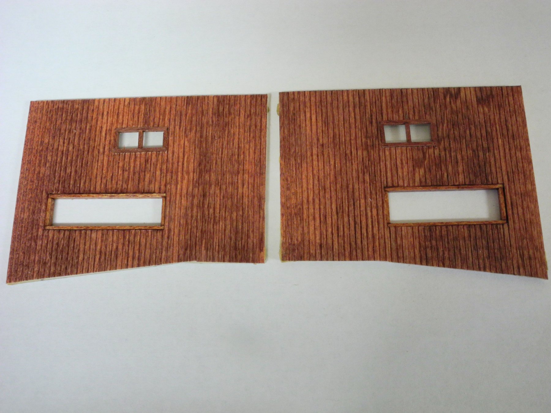
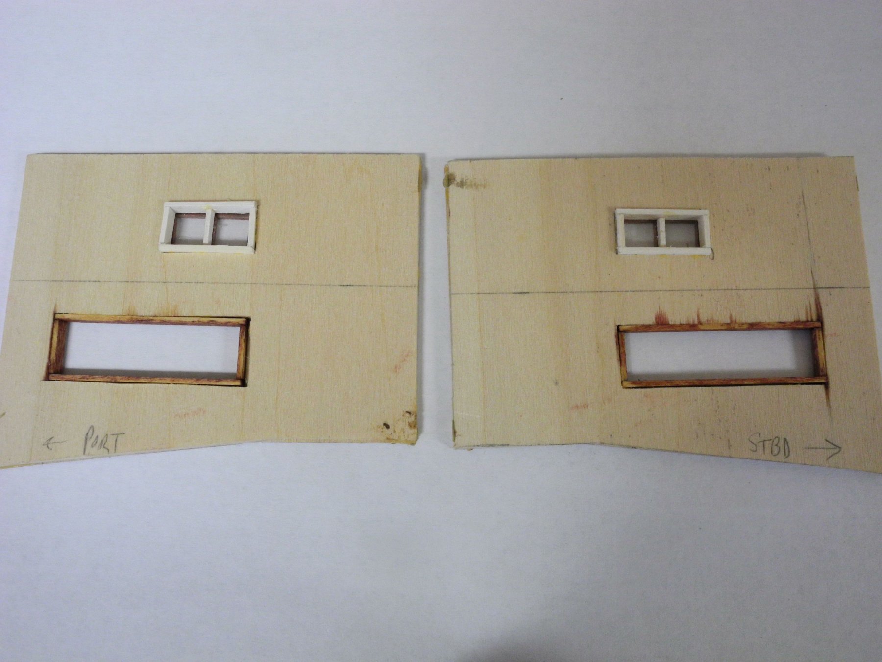
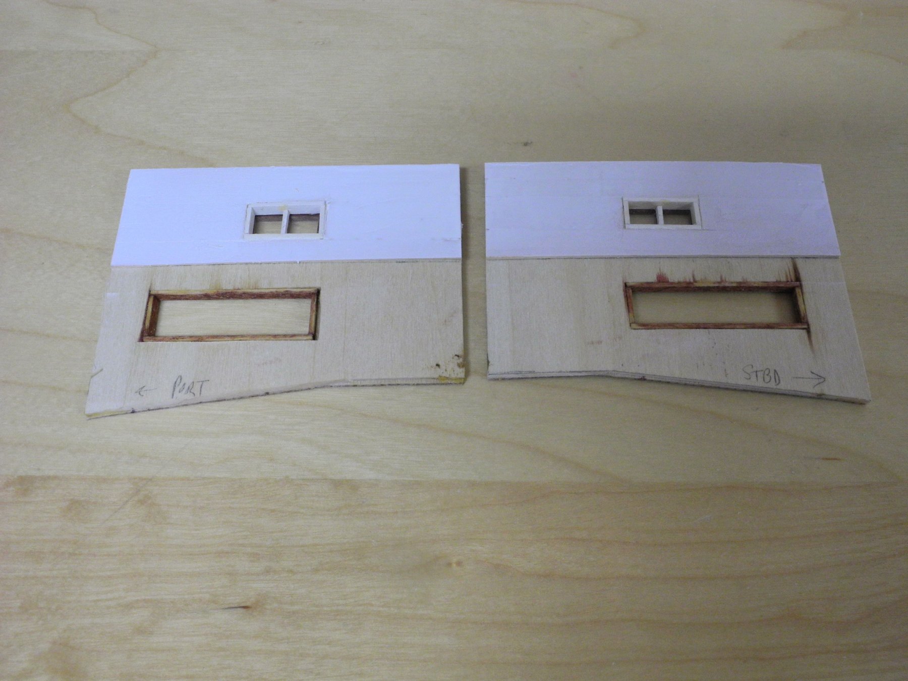
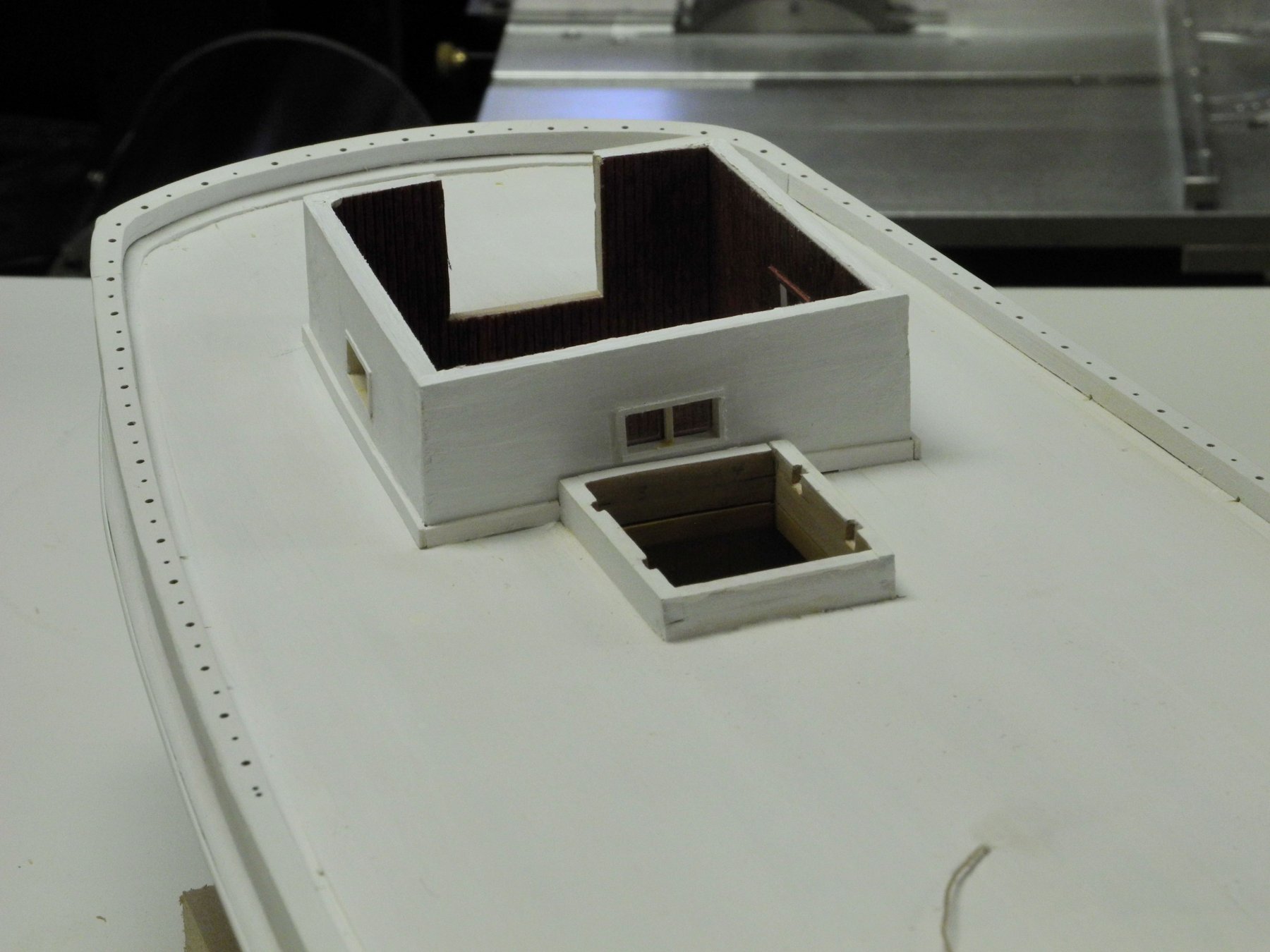
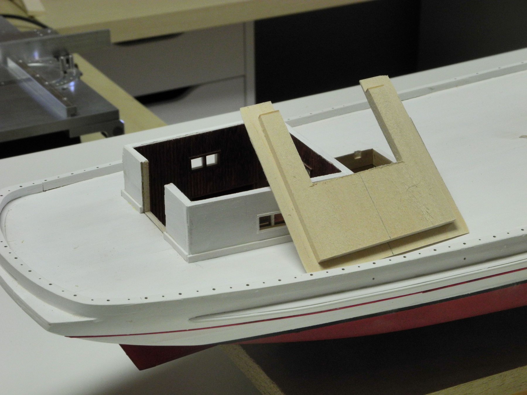
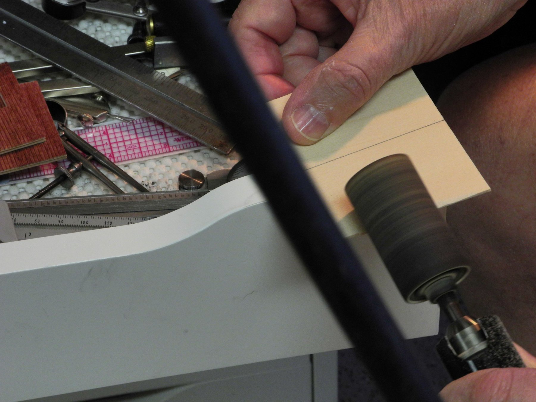
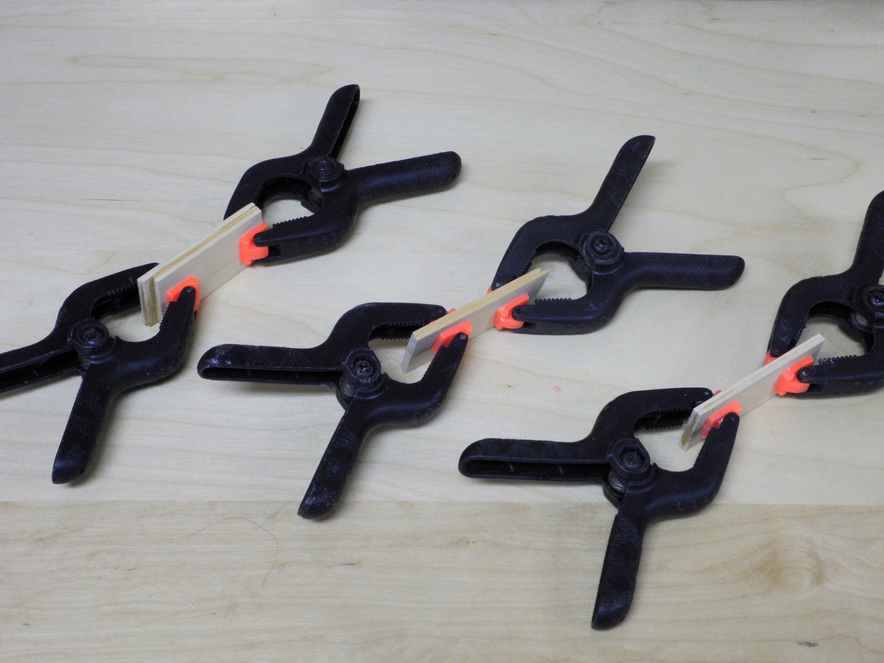
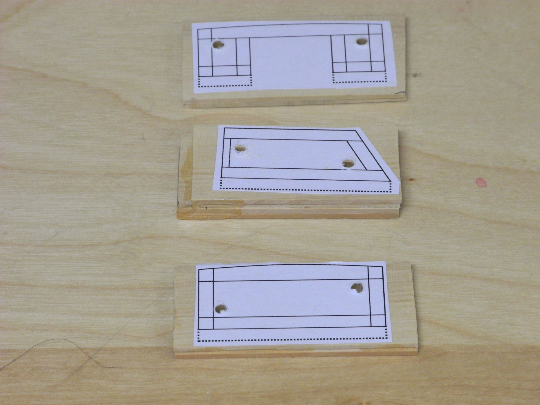
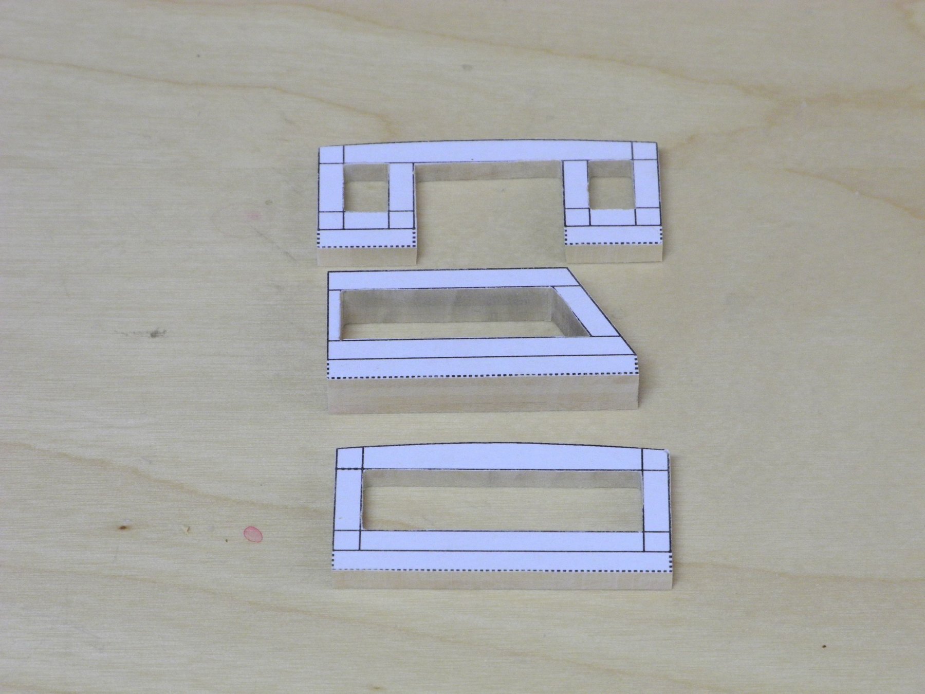
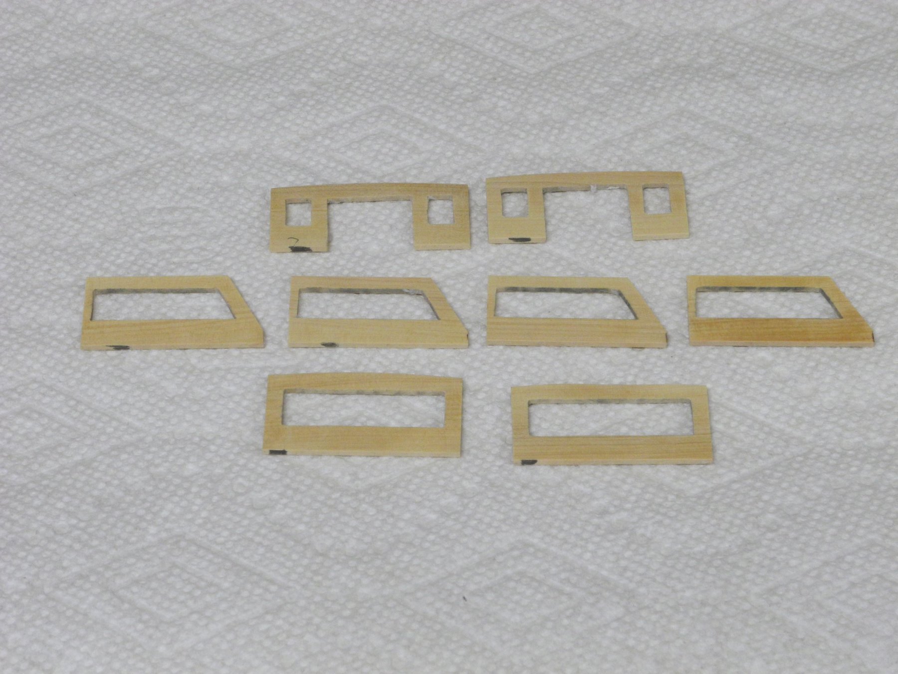
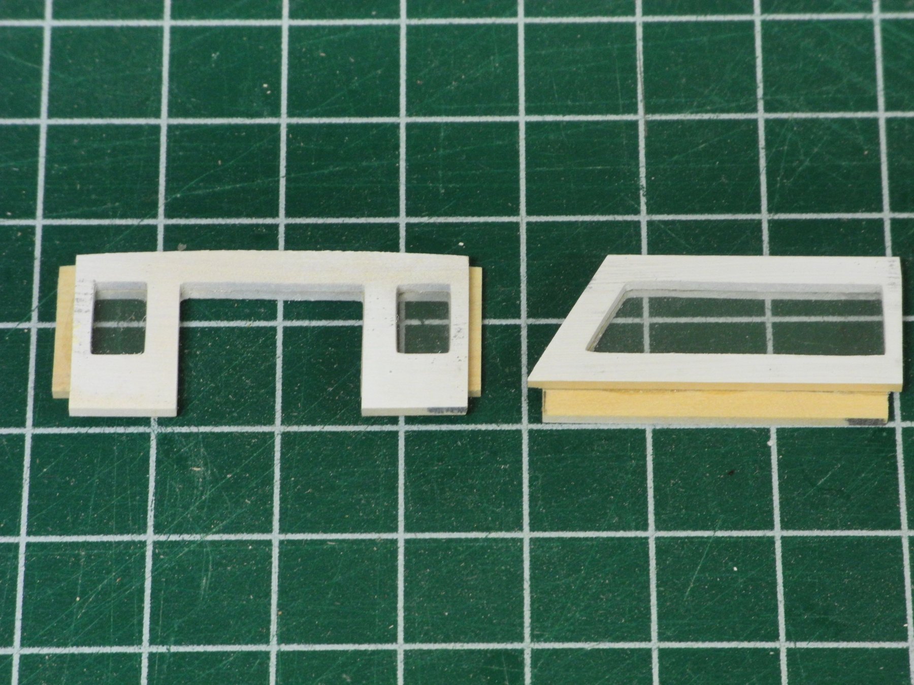
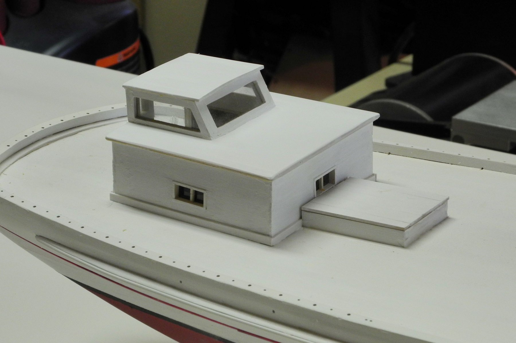
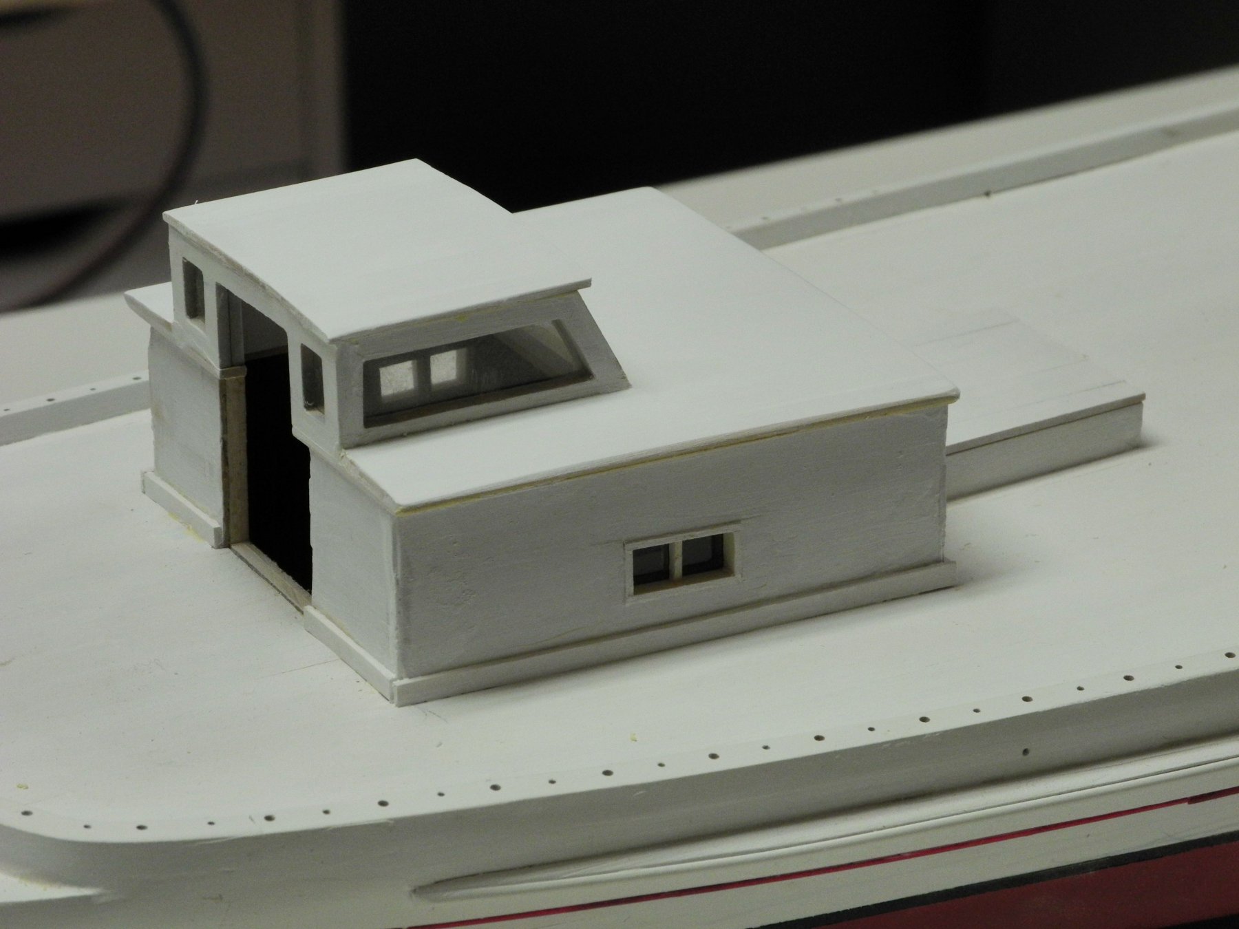
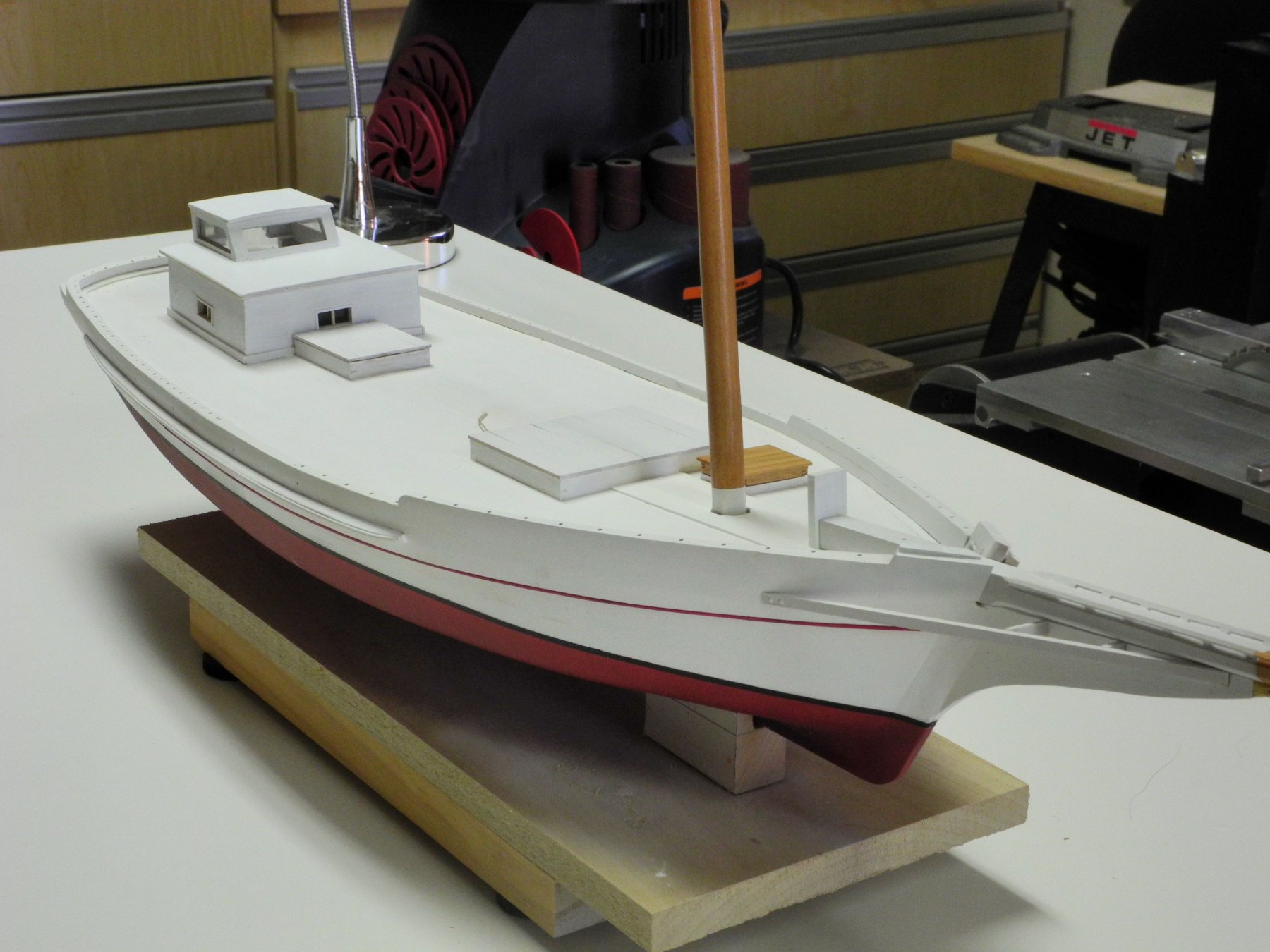
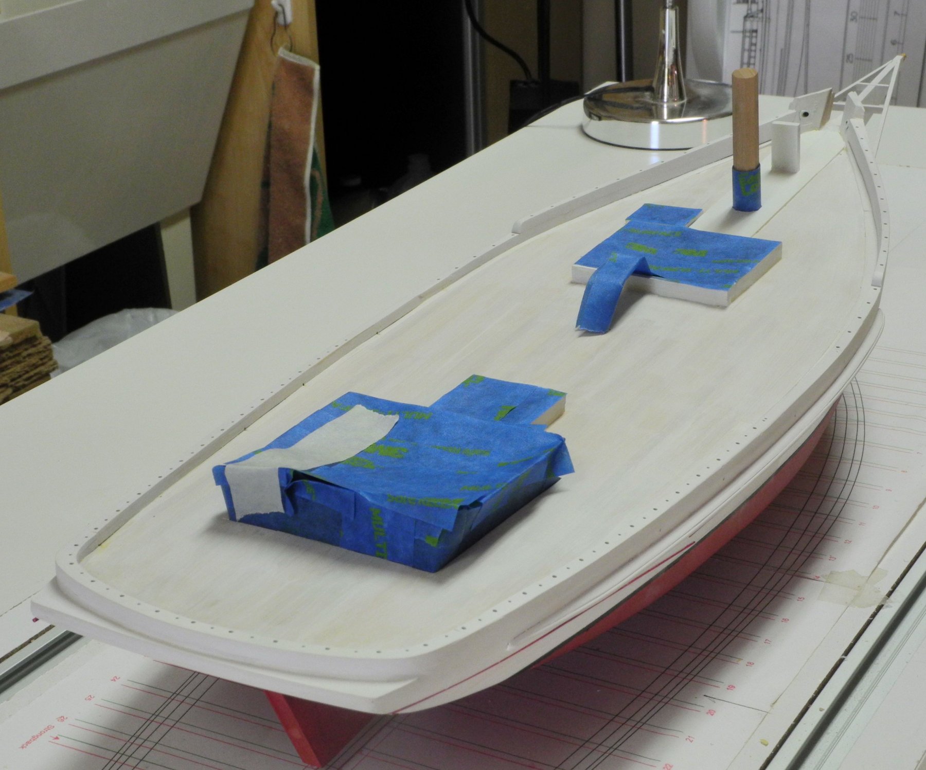
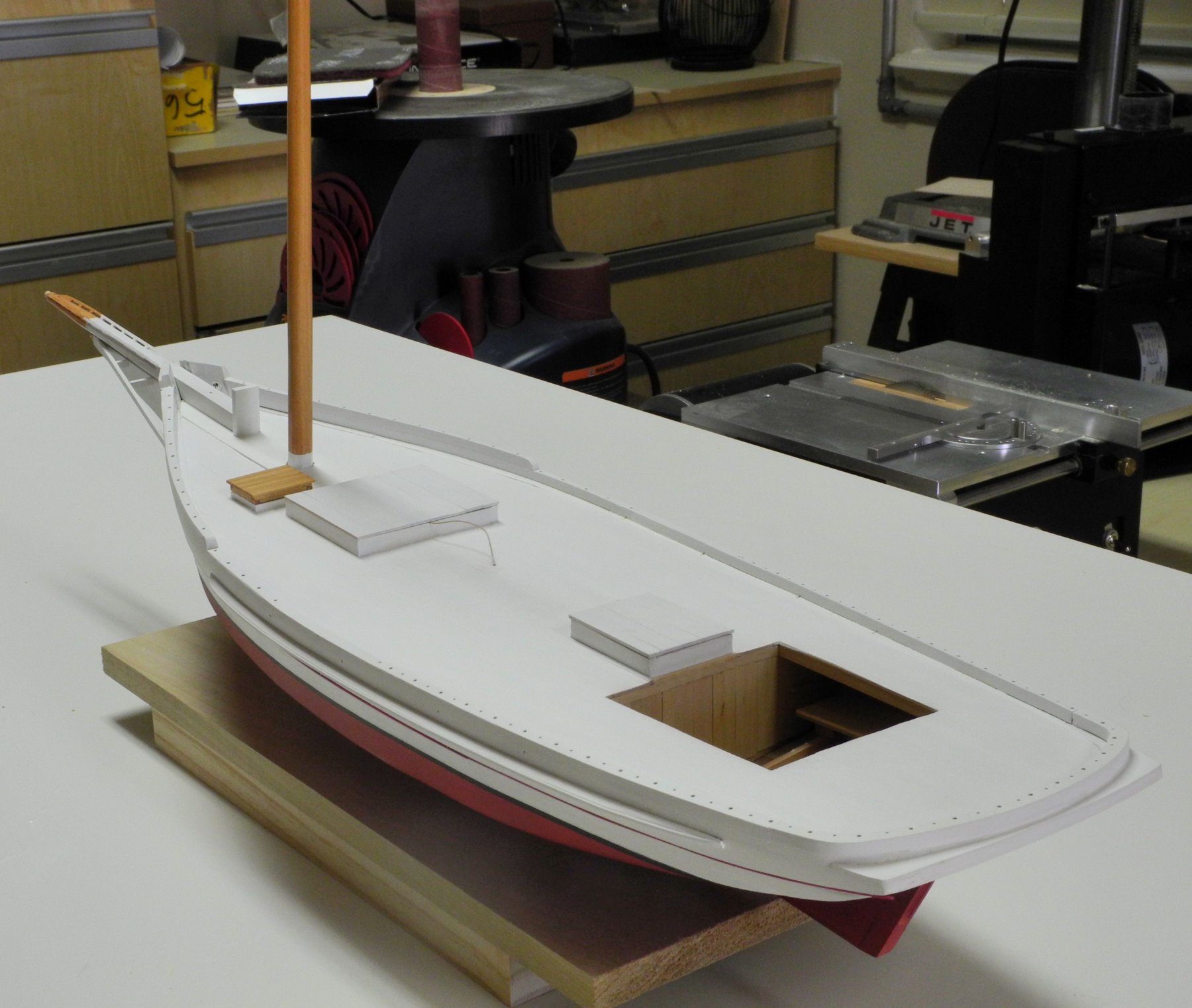
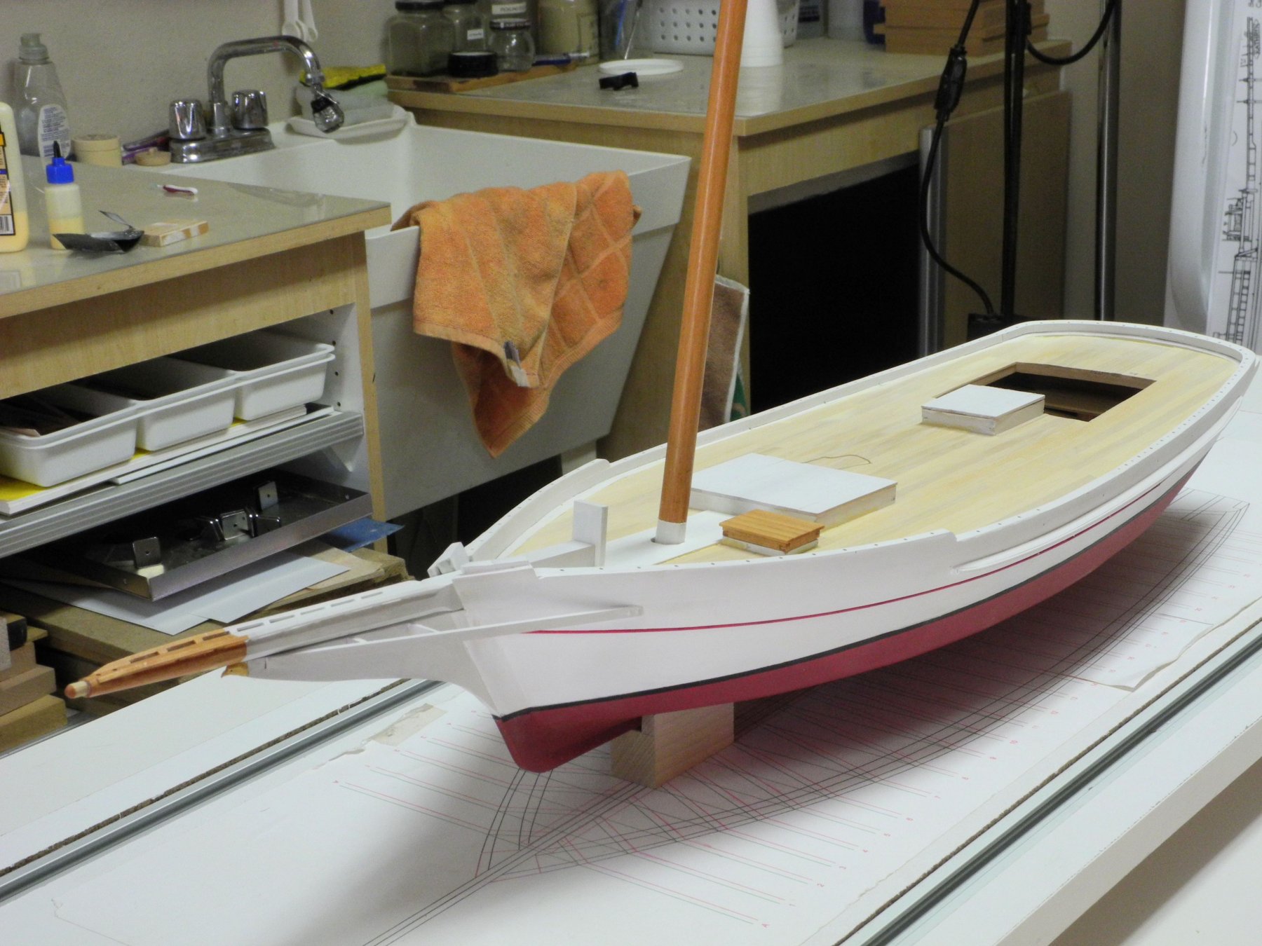
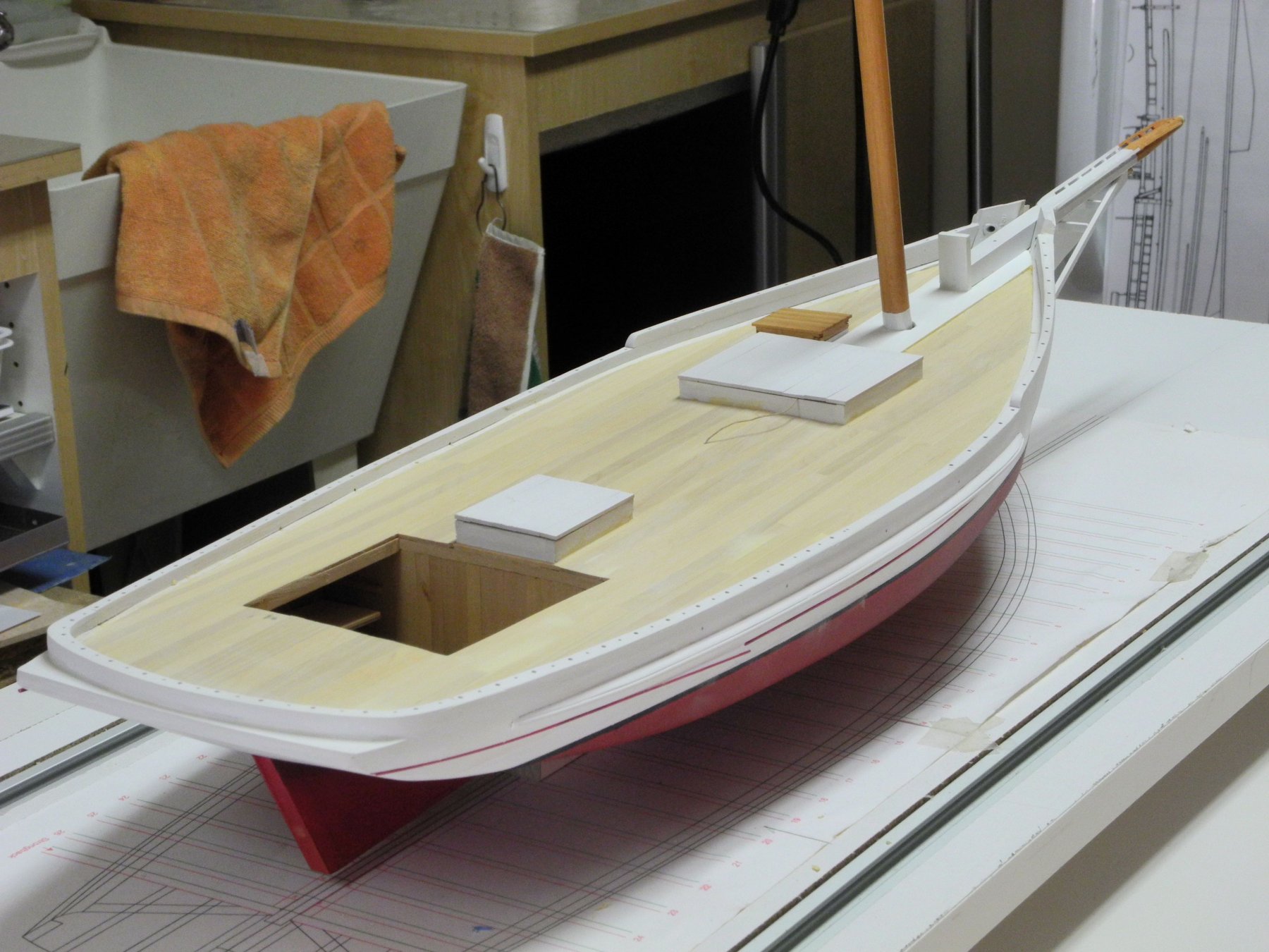
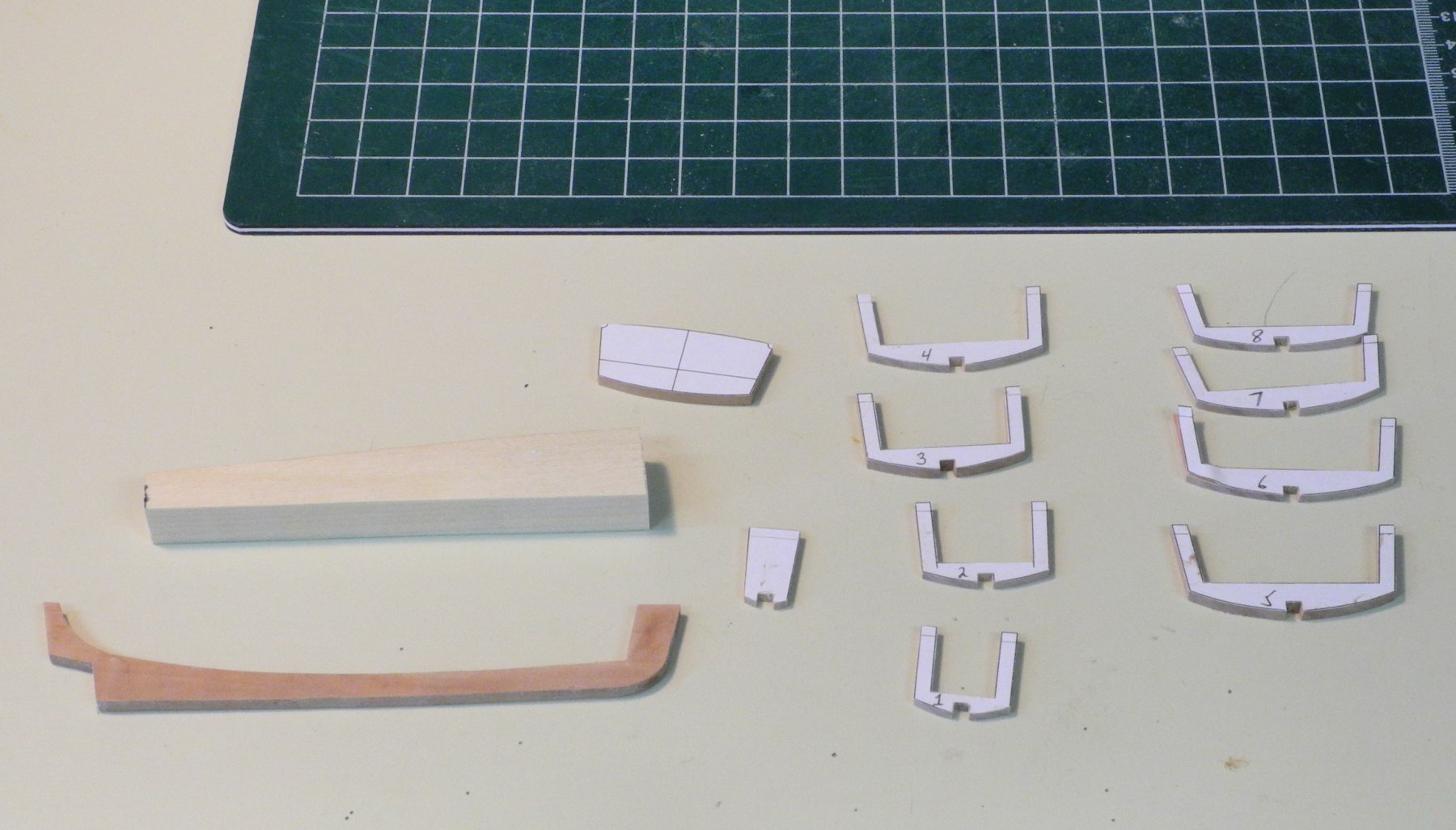
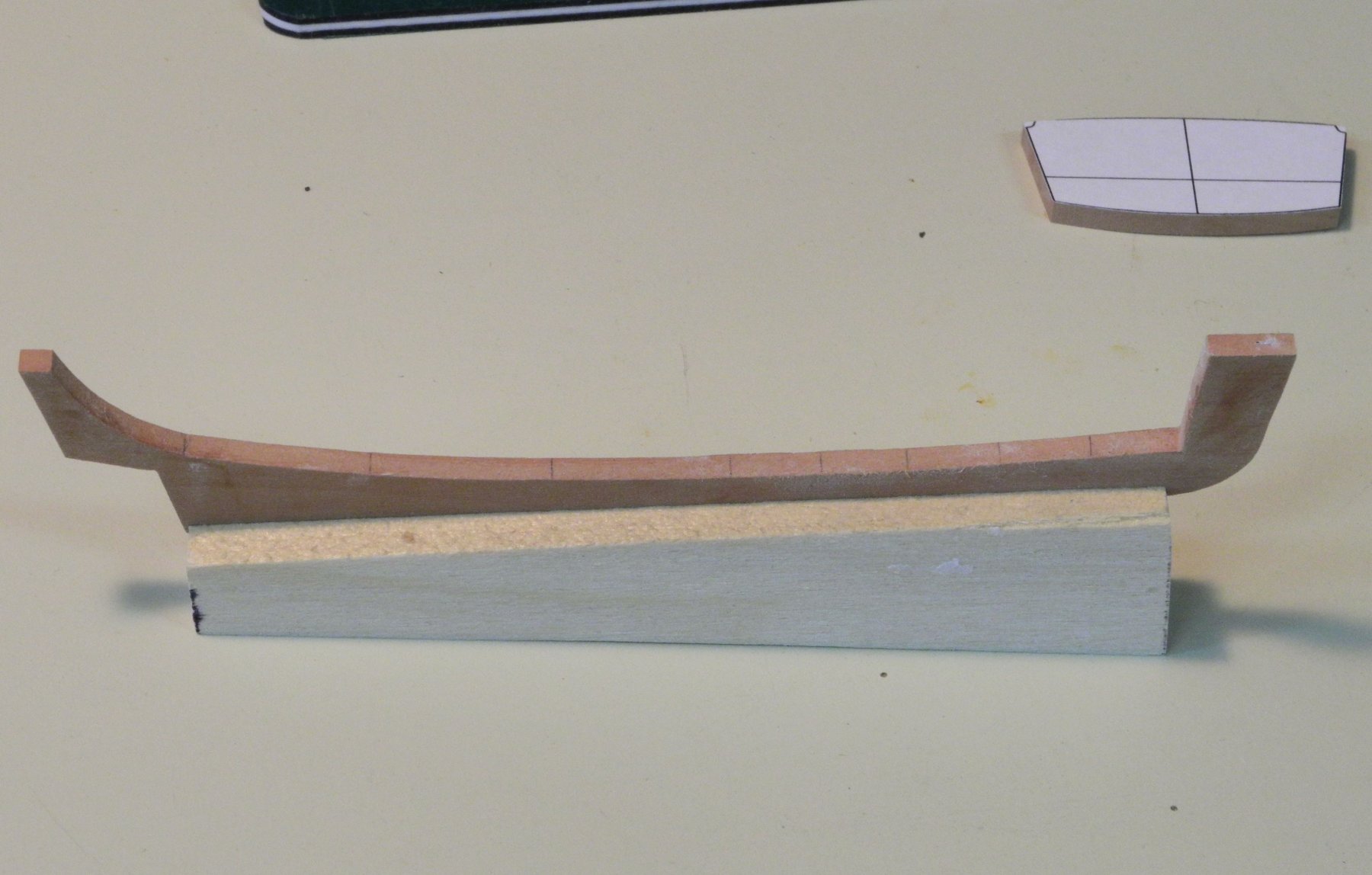
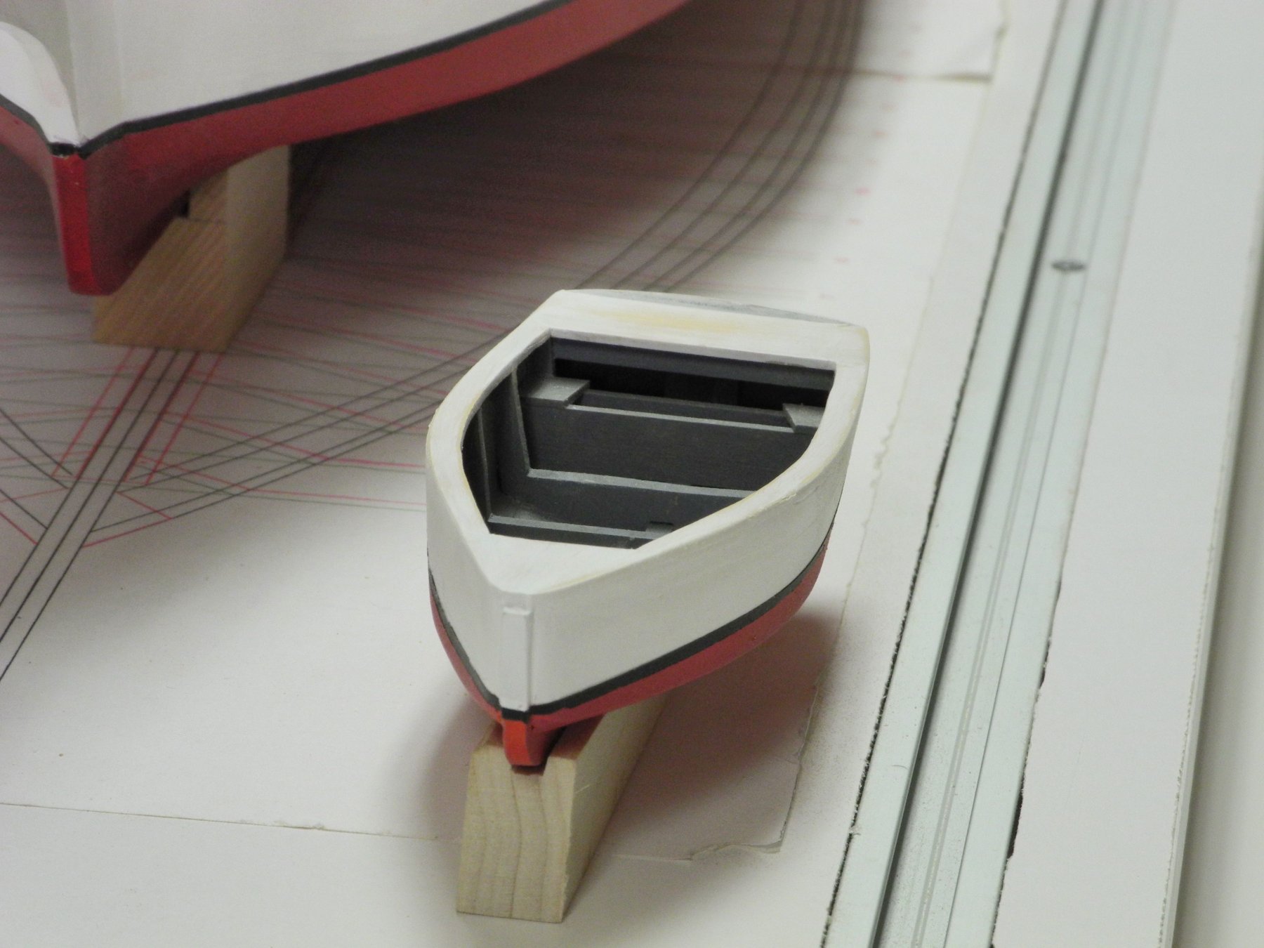
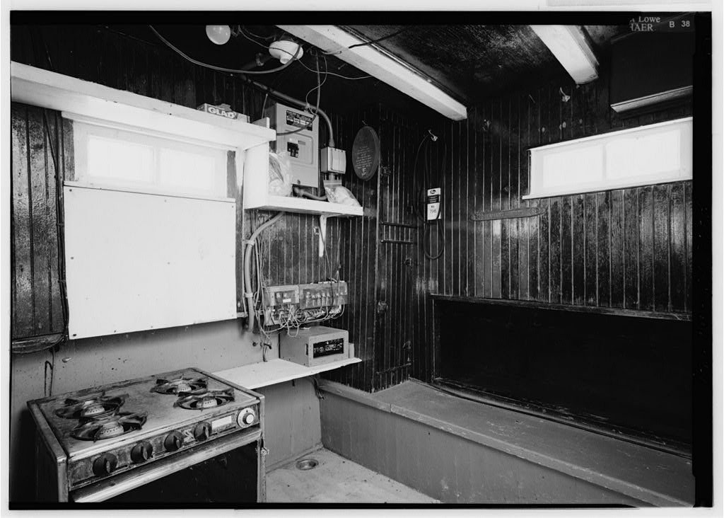
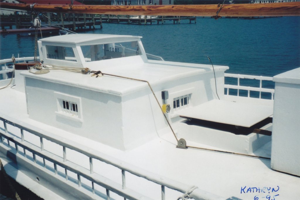
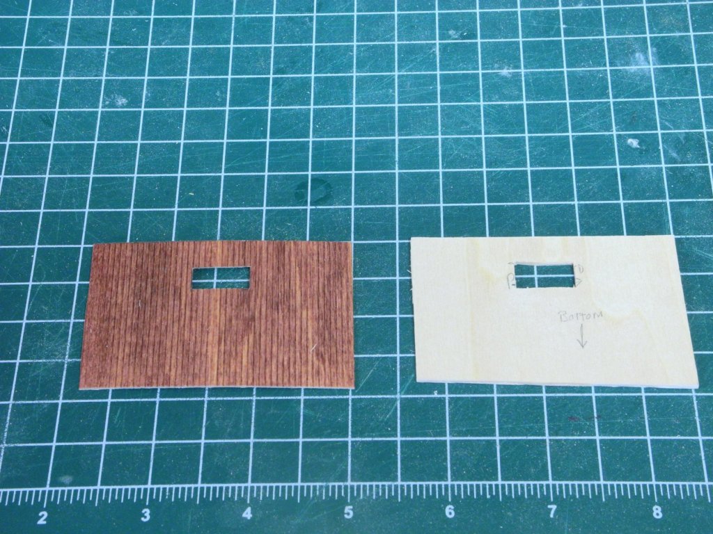
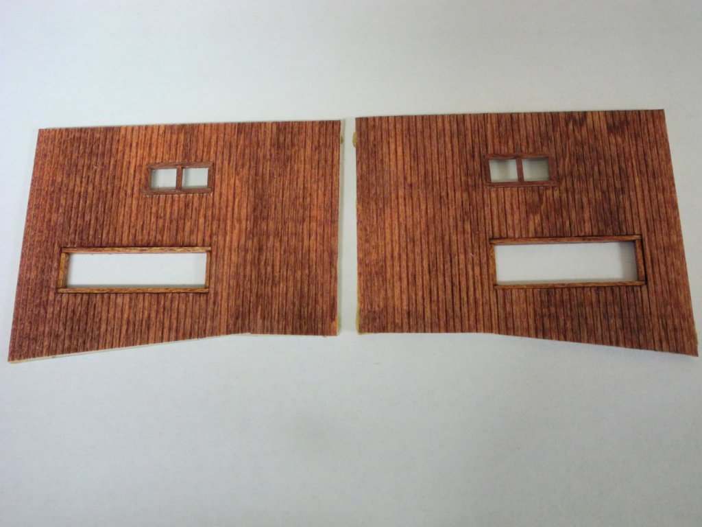
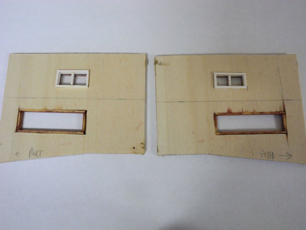
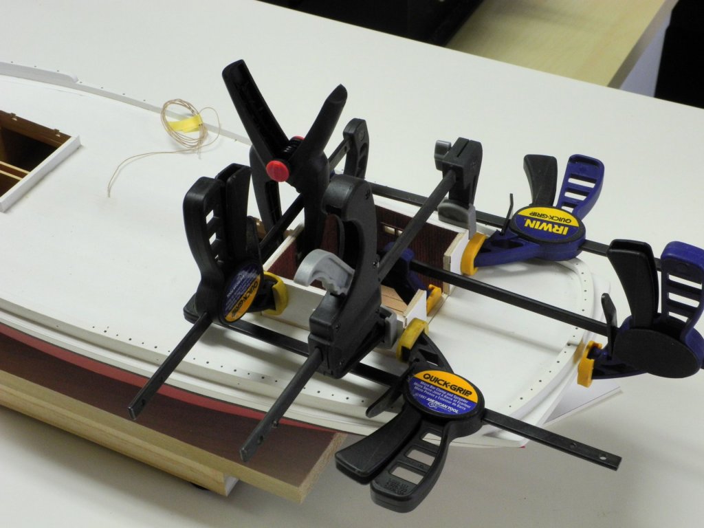
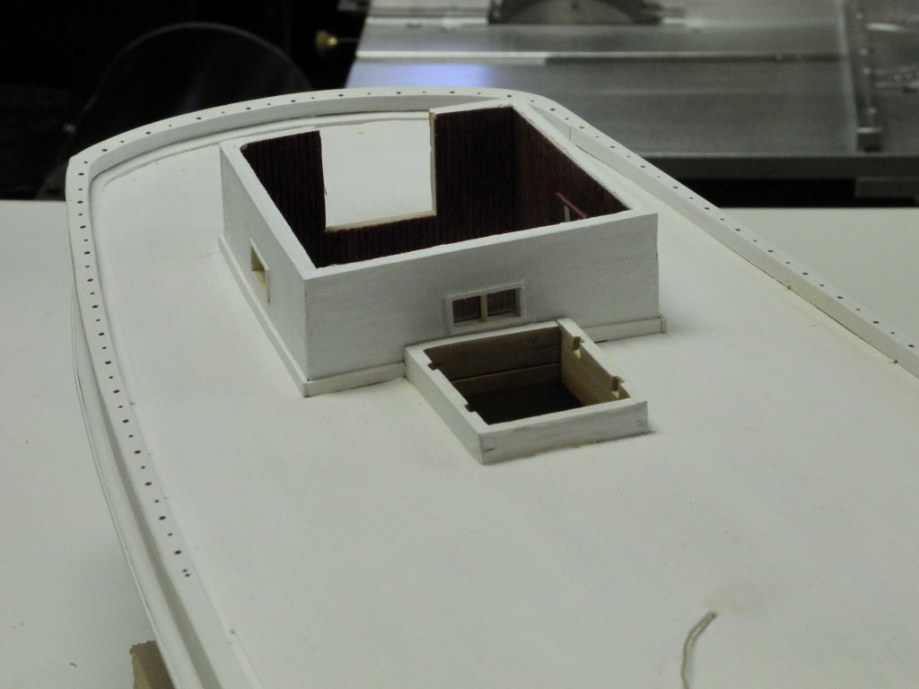
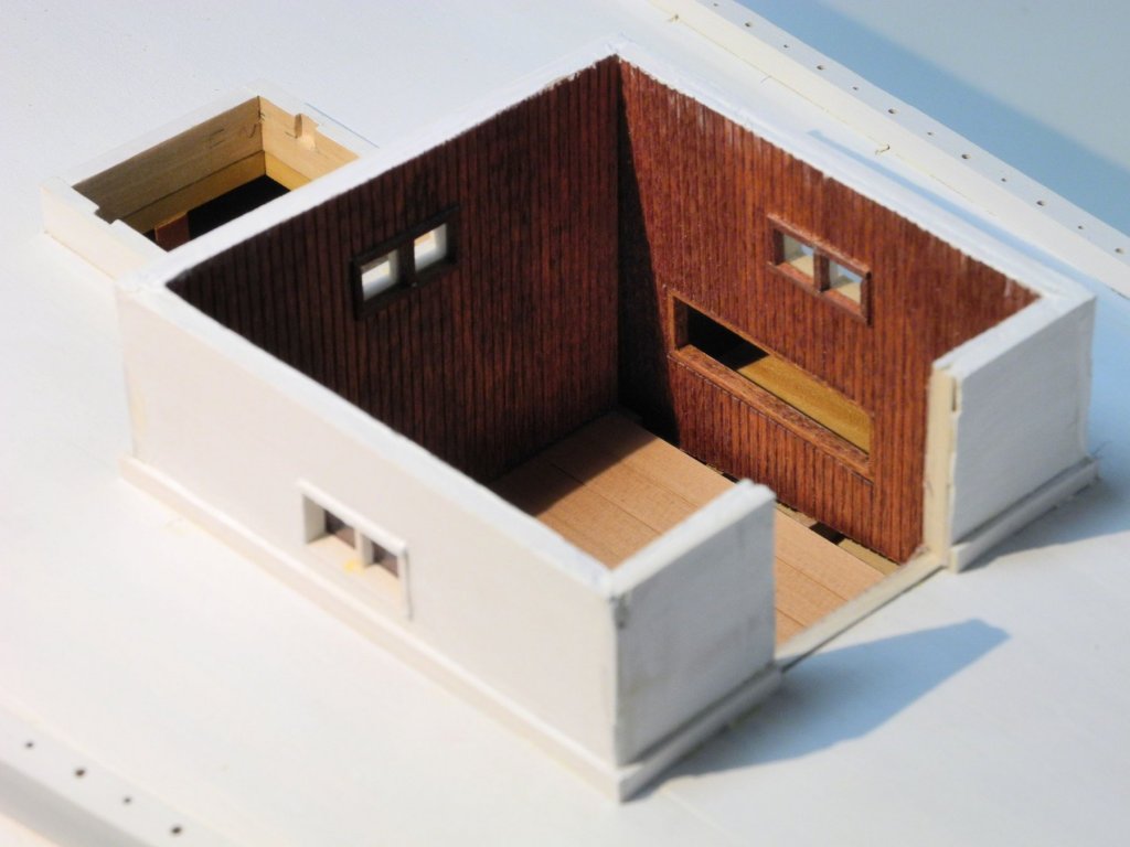
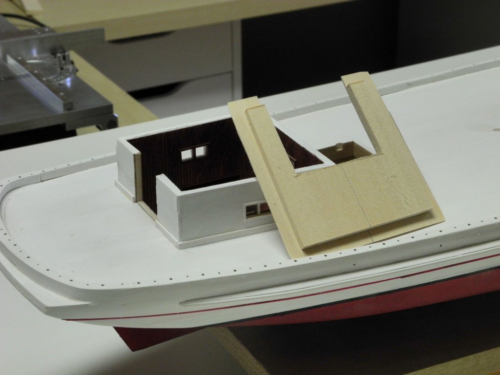
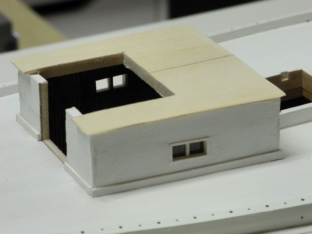
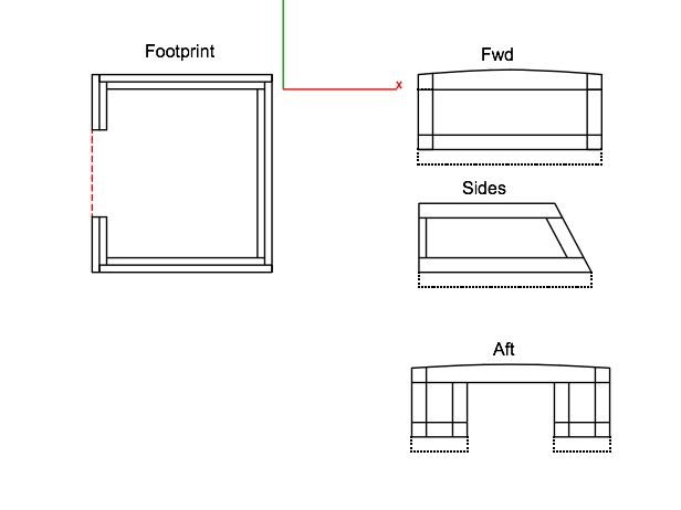
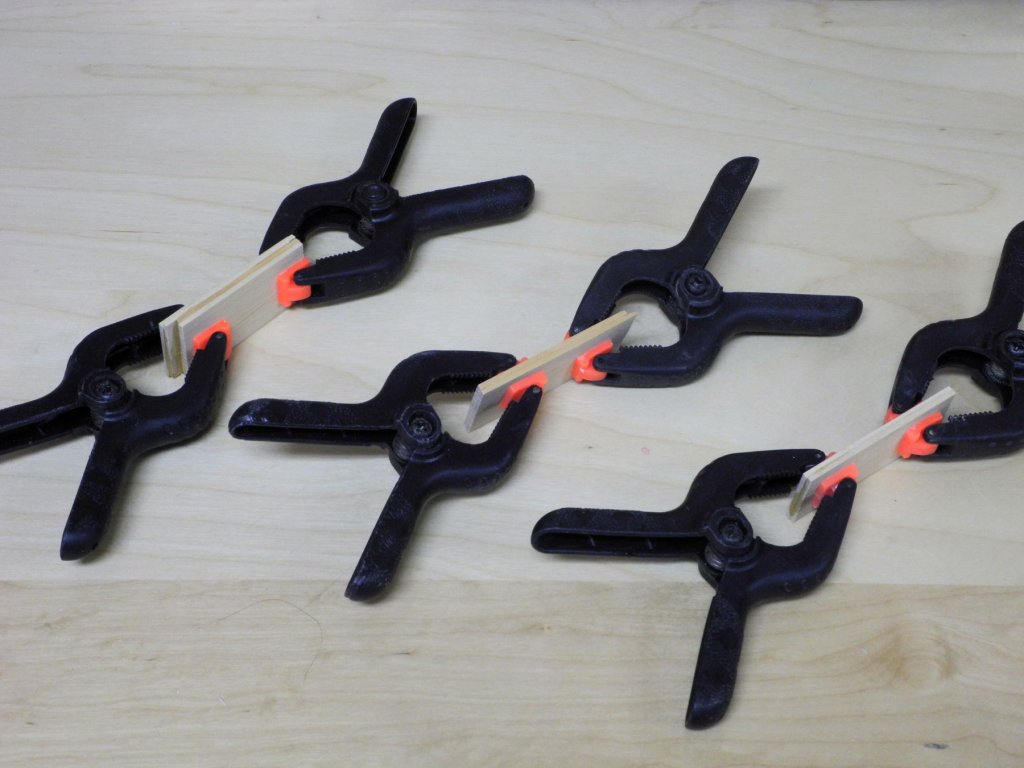
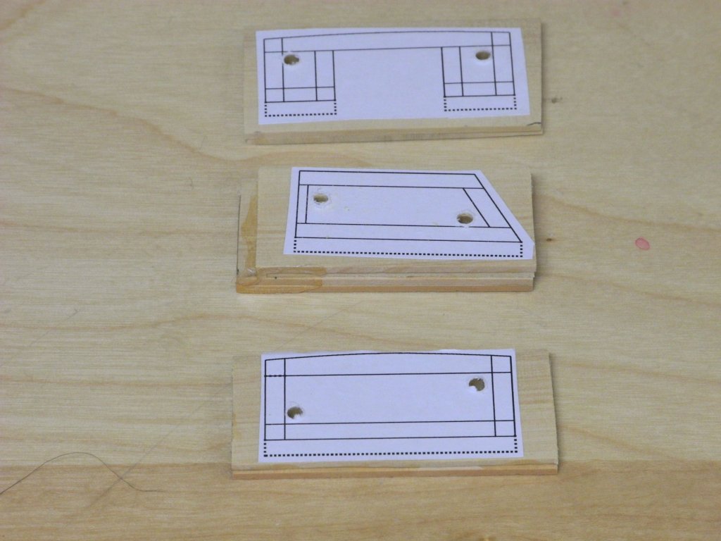
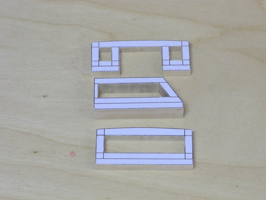
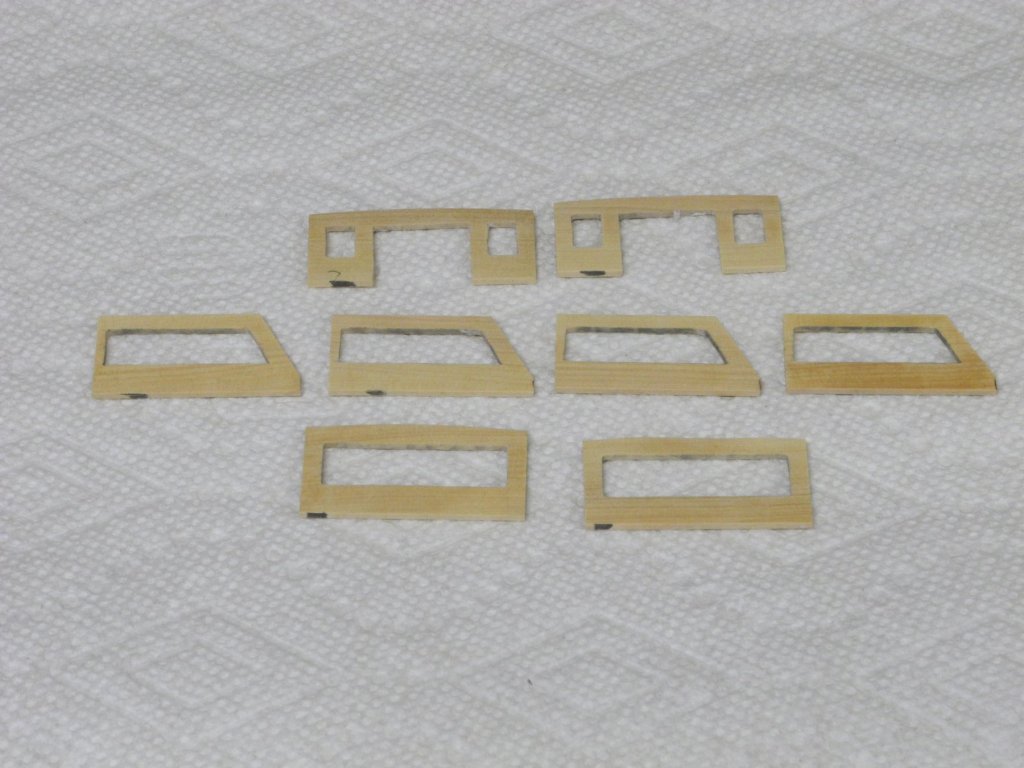
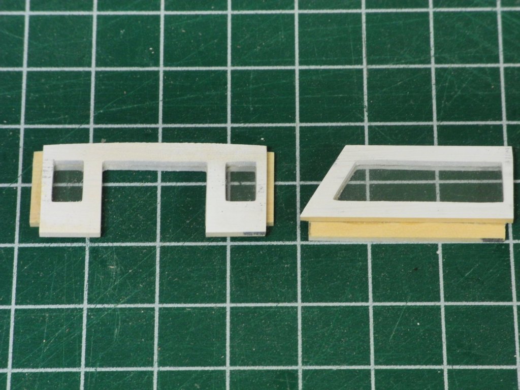
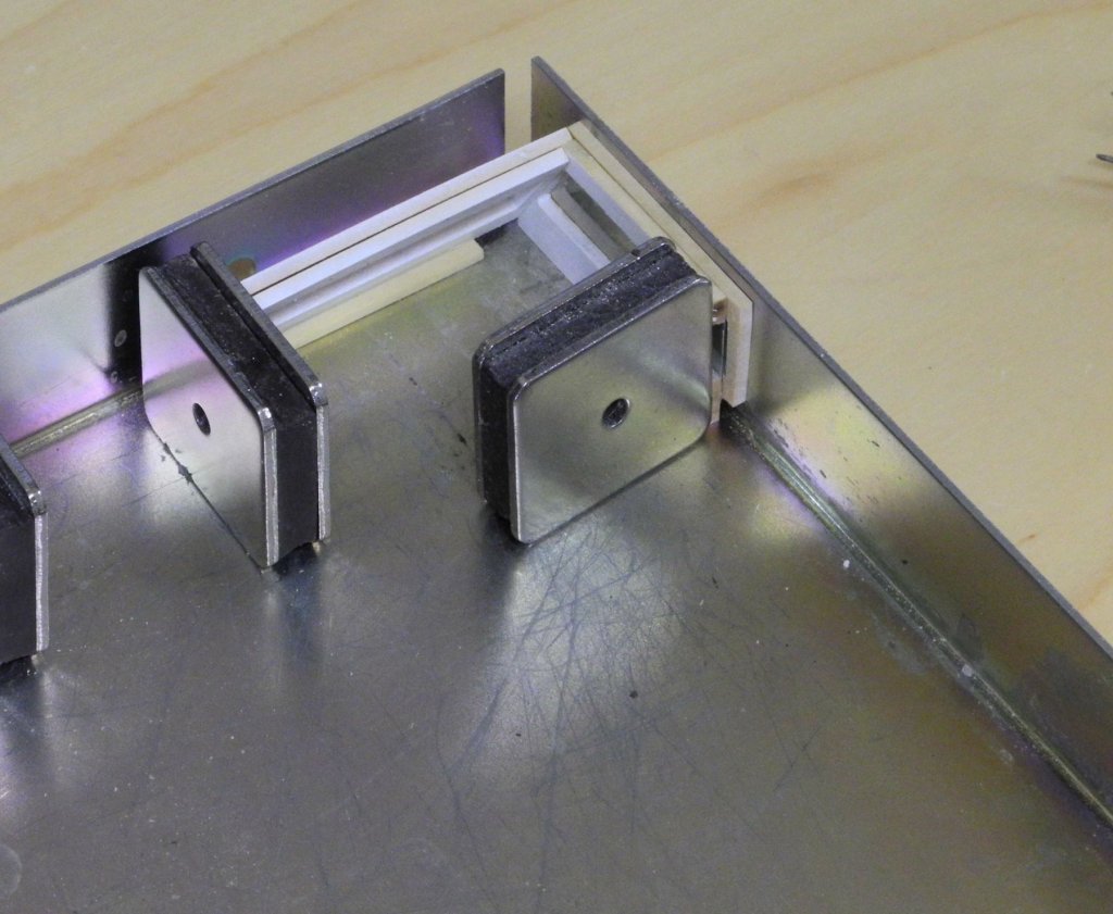
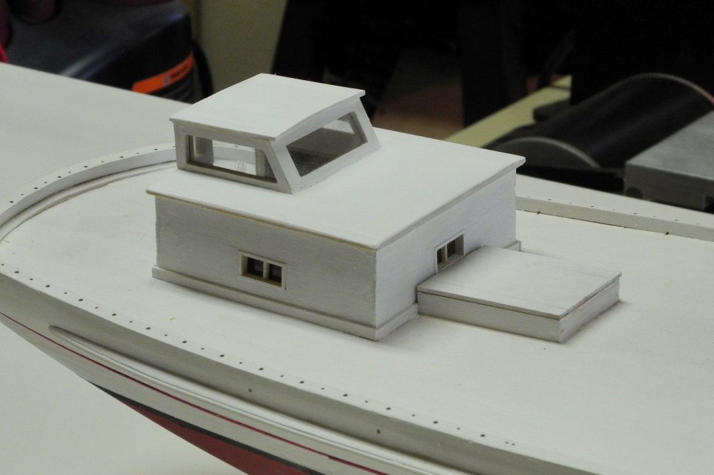
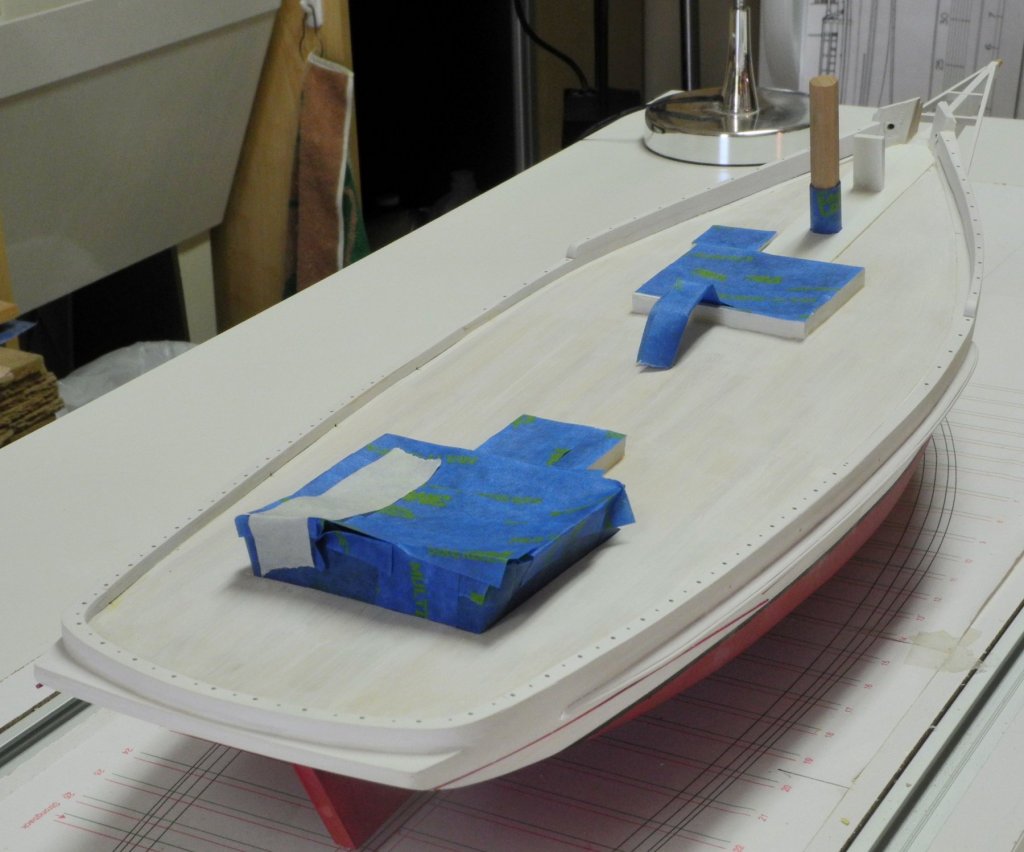
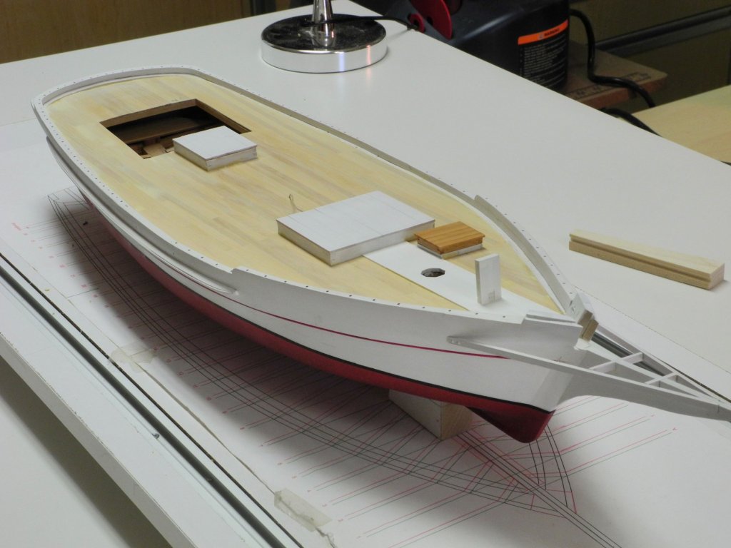
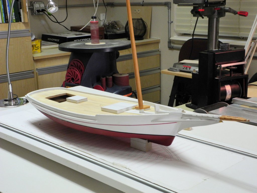
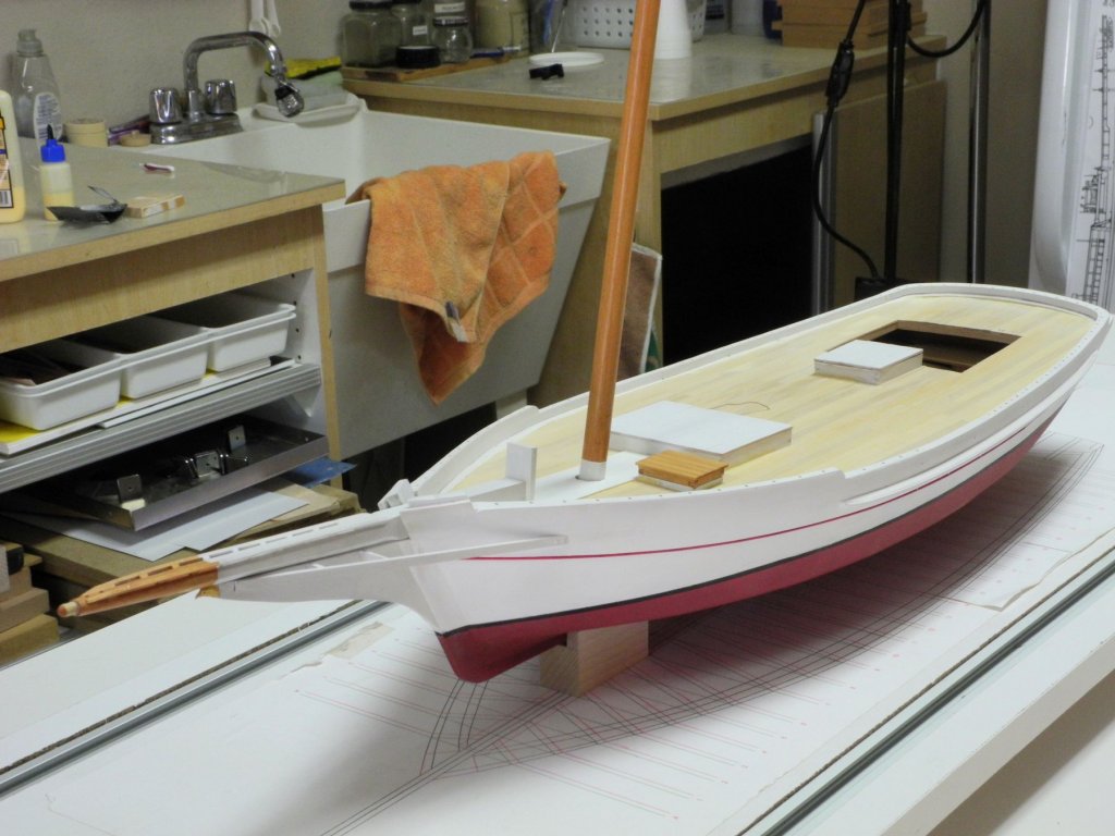
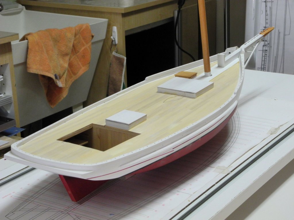
 Part 41 – The Cabin Hi Everyone It has been quite a while since my last post. Most of the time was occupied by a long vacation trip that included Michigan, Ontario Province in Canada, Vermont, New York, New Jersey, down through Maryland and ending in Virginia – lots of driving!. During the trip we got to see relatives, old friends, and some new friends. A stop in Maryland allowed a visit to the real Skipjack Kathryn, where I was able to take some photos of the details that will be part of the model work yet to be done. Since returning from the trip I’ve been working on Kathryn’s cabin. Kathryn’s cabin interior includes windows in each side wall and in the forward wall. It also includes openings in the side walls and the aft wall for access to the berths that were previously constructed under the deck beams. The following are two photos from the HAER files showing the cabin interior. Kathryn’s cabin has a ‘doghouse’ – a small structure with larger windows – presumably to add light and a little more headroom in the cabin. This doghouse was added to the cabin after the original build but before the HAER survey. After a bit of time attempting to develop a plan for framing out the cabin and constructing the cabin’s interior and exterior walls, benches, and cabinets, I decided that this approach would probably be more difficult than I wanted to attempt. Instead, I developed an approach that would provide the realistic appearance and would be within my capabilities. The model’s cabin walls consist of a basswood form with the openings for the windows and the berth openings. This form is sandwiched by paneling on the interior and planking on the exterior, and is the thickness of the studs that would have been used in framing. The following photo shows the form and the paneling for the starboard wall. The paneling is a piece of scribed deck planking stained with Minwax Sedona Red. After the openings for the windows and berth access were cut, a piece of transparency film was glued over the window opening in the interior face of the cabin form. This simulates the glass of the window. The openings in the paneling were framed out. The panels were then glued to the form. The window in the exterior face of the assembly was then framed out with framing pieces that had been pre-painted. The exterior face of the assembly was planked down to the level of the deck. When this work was completed for all cabin walls, the walls were then glued in place. Molding was installed around the base of the cabin. The following photo shows the interior of the cabin. The cabin deck still needs to be painted, and the settees and cabinets need to be installed. A short companionway ladder will lead from the main deck down to the cabin deck. At this point I need to point out an error I had made in Kathryn’s construction: the cabin opening and the aft hatch are too close together. There should be about 3/8” space between them. This resulted from a drafting error that I hadn’t picked up until too late. I thought about doing some surgery on the deck to move the hatch forward, but the stanchion under the deck beam that supports the forward hatch coaming prevented this. So the model will remain as it is, with the cabin too close to the hatch. The roof of the cabin has an opening for the doghouse mentioned above, and has a camber that is the same as the deck camber. Since the roof of the model needs to be removable in order to view the cabin’s interior, a form was developed that would provide a snug fit to the cabin opening. Another form in the outside dimensions of the cabin roof was glued to the first form, as shown in the following photo. The roof camber was then shaped using a sanding drum on a Foredom flex shaft tool. Each wall of the doghouse would be of two-piece construction, with the sides overlapping as in the following photo of the plans for the doghouse. The dotted lines on each wall indicate tabs that would be left on the interior piece of the wall to allow accurate mounting. Since the openings in the two pieces of each wall need to be identical, the pieces were first glued together so that they could be shaped together. In the above photo, the four pieces for both side walls are all glued together so that the side walls would be identical. The drawing of each wall was glued to the appropriate set of wall pieces. The walls were cut out on the scroll saw and final shaping was performed using the sanding drum and small files. The wall pieces were separated in an acetone bath. In the above photo it can be seen that marks were made on the bottom of the pieces prior to separation – this allows the pieces to be properly aligned. The inner piece of each wall had a piece of transparency film glued to it to simulate window glass. The outer piece of each wall was trimmed to remove the tab from the drawing. The ends of each wall were trimmed where appropriate to allow the overlapped construction mentioned above, and each wall was then assembled. The following photo shows a side wall and the aft wall shaped and assembled. The front and side walls were glued together in a magnetic squaring jig before the doghouse was glued to the cabin roof. The roof of the doghouse and the cabin roof were planked and shaped, and then were painted. The following photos show the cabin roof and doghouse. The cabin interior needs to be completed, and doors need to be added to the aft wall of the cabin. The following photo shows the current state of the model. Thanks everyone! It’s good to be back and making some progress on Kathryn.
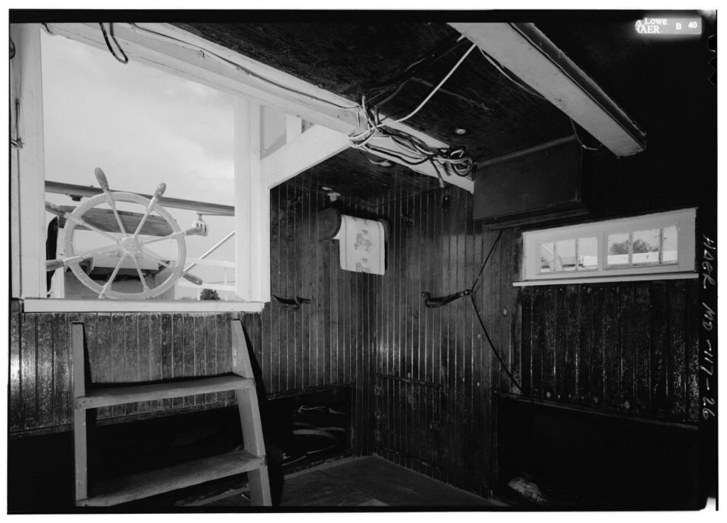


- 878 replies
-
- 19
-

-
Great progress Ed. Your posts are a great tutorial on rigging the model. I believe the techniques you show can be used on any rig.
- 3,618 replies
-
- 3
-
-
- young america
- clipper
- (and 1 more)
-
Hi Patrick The photo sequence really shows how all the detail comes together - I love it! Wonderful work.
-
Hi Ed - I tried to send you a PM but you're 'not receiving messages' - maybe a full mail box?
- 3,618 replies
-
- 2
-
-
- young america
- clipper
- (and 1 more)
-
Recommendations For A Good Milling Machine
Mahuna replied to Thistle17's topic in Modeling tools and Workshop Equipment
I agree with your feelings about Sherline's customer support. I've had many dealings with them and all have been positive experiences. -
Hi Patrick Welcome back - glad to see more progress on Shadow. The details continue to be amazing.
-
Thanks Patrick. LOL - it's probably the size of your Shadow with nowhere near the details.
-
Really nice work, Ken. This will be a unique model.
-
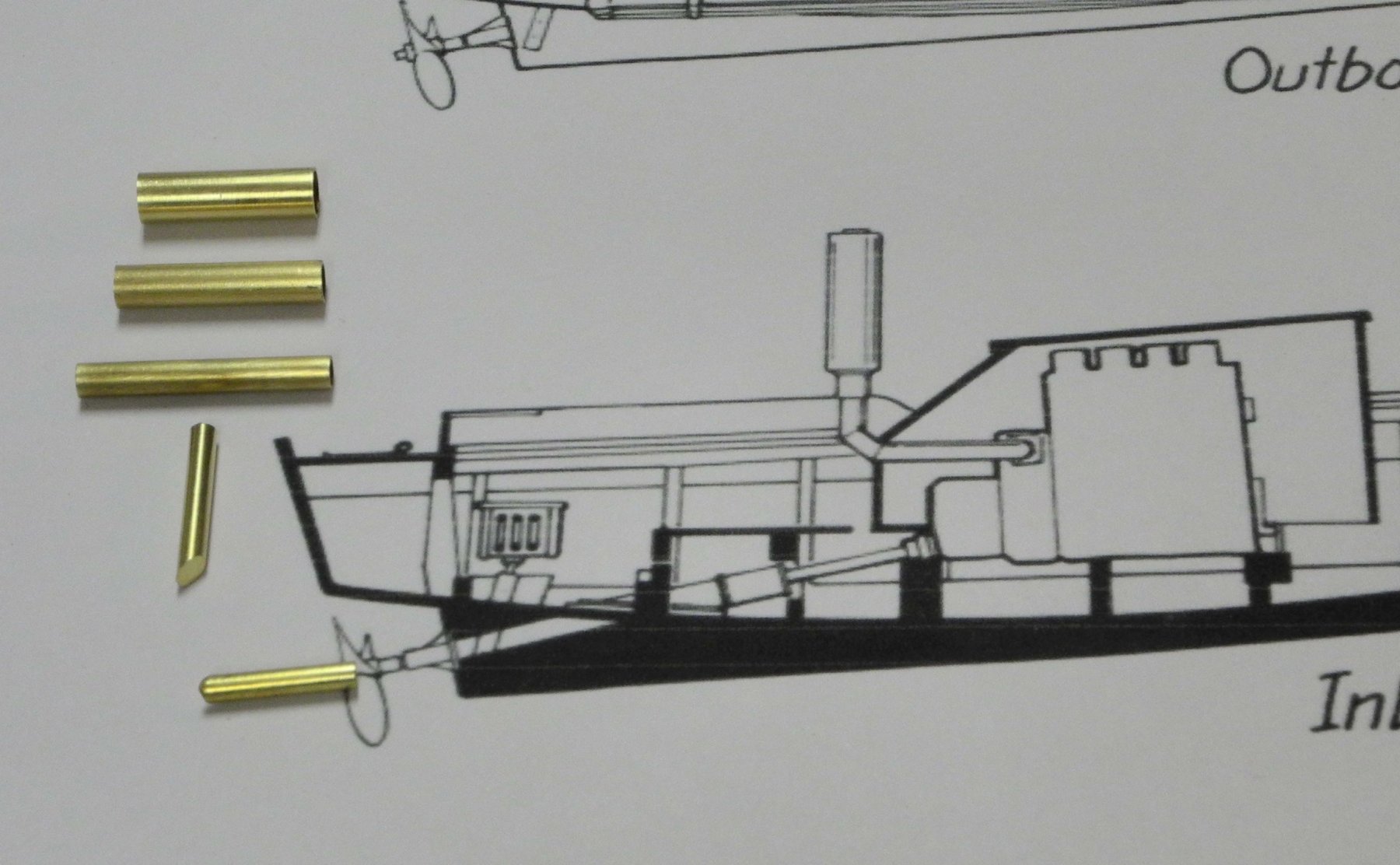
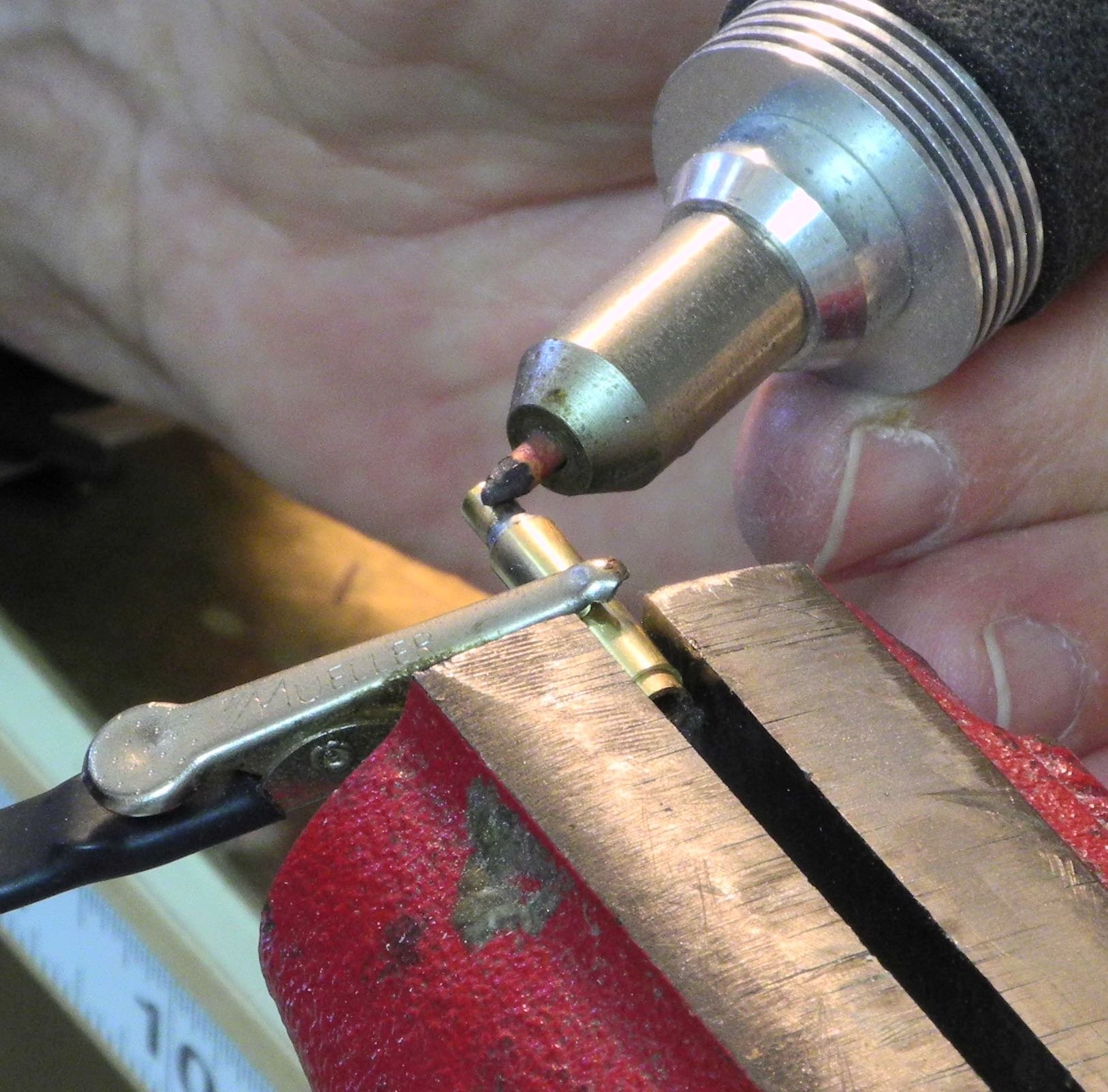
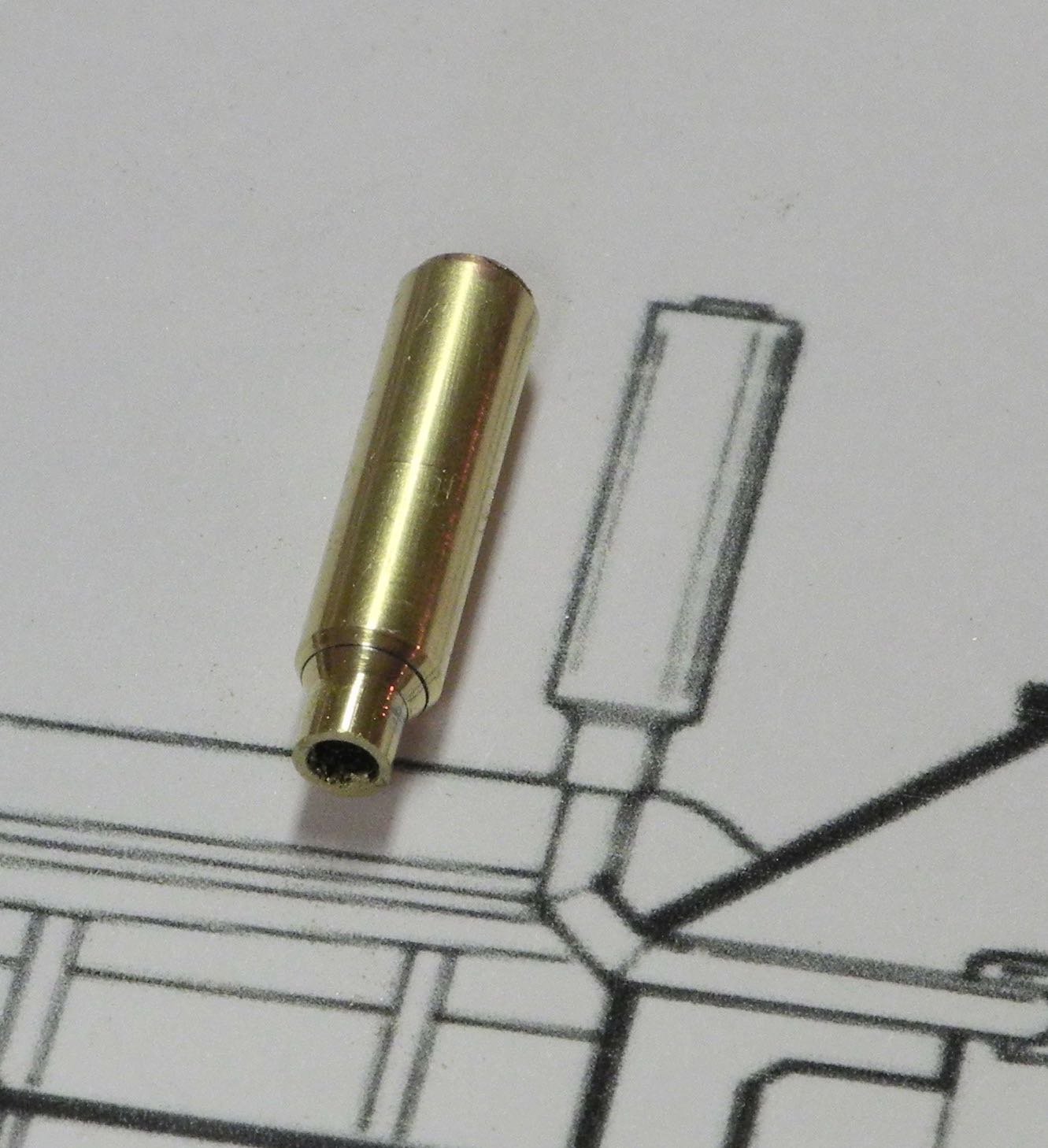
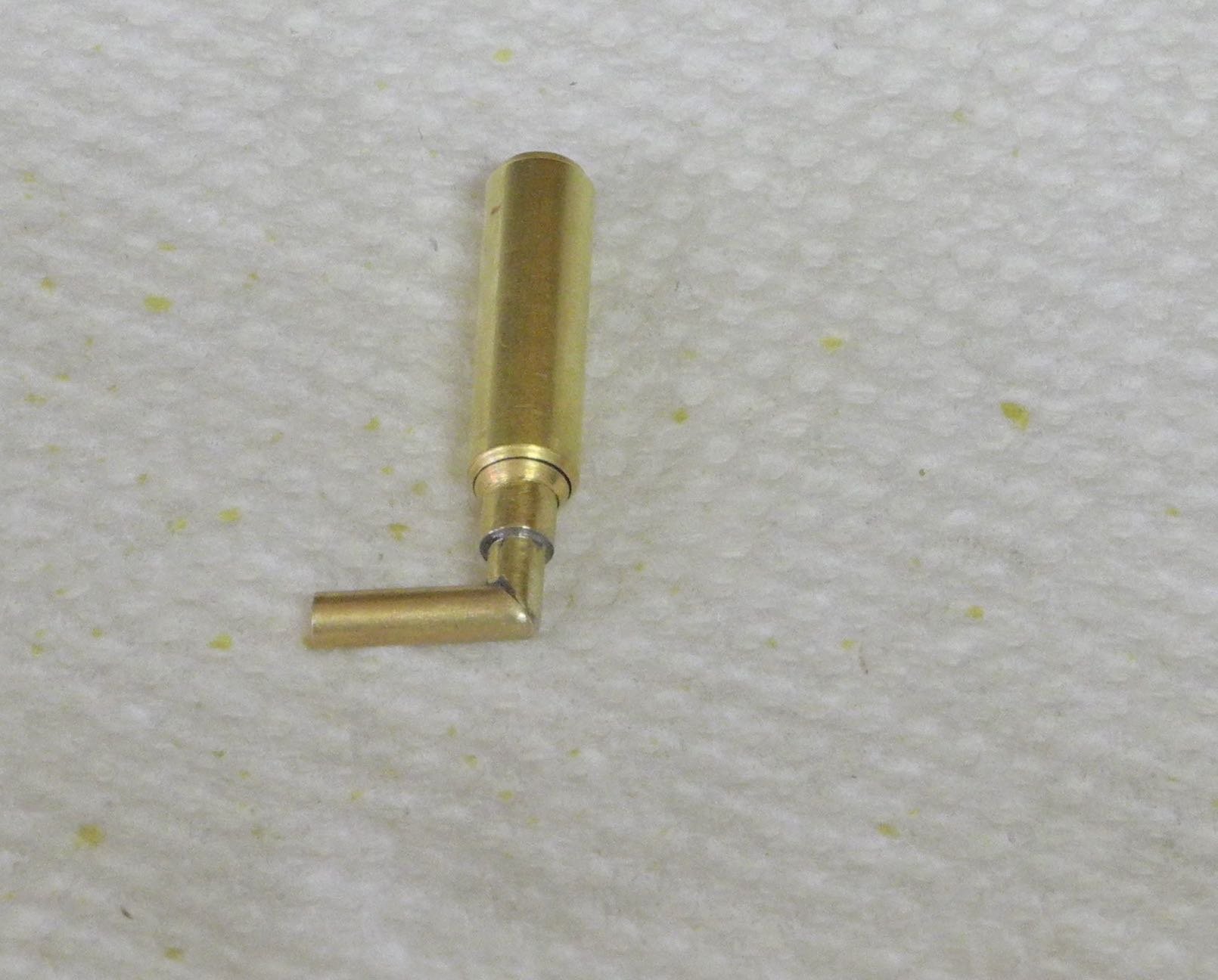
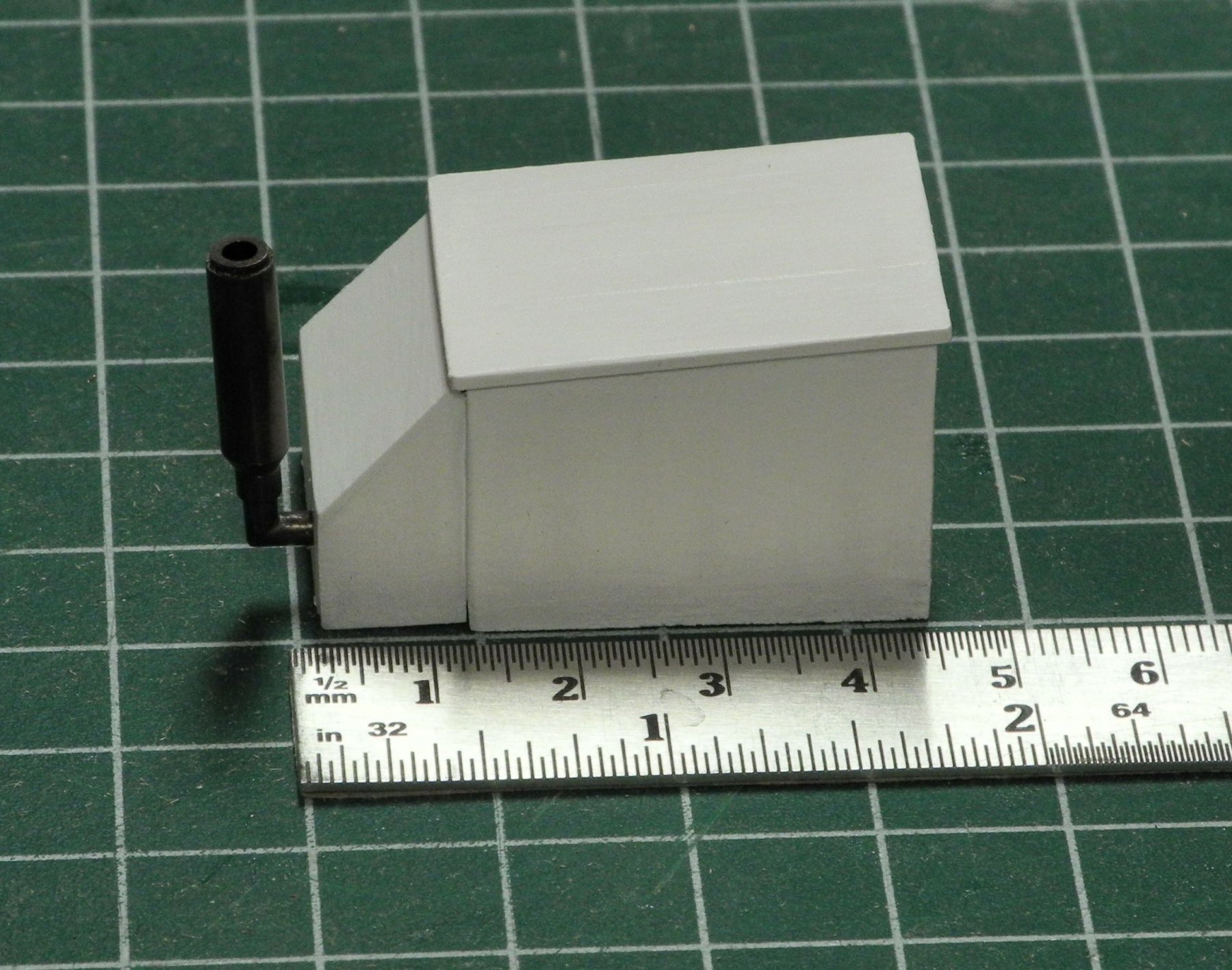
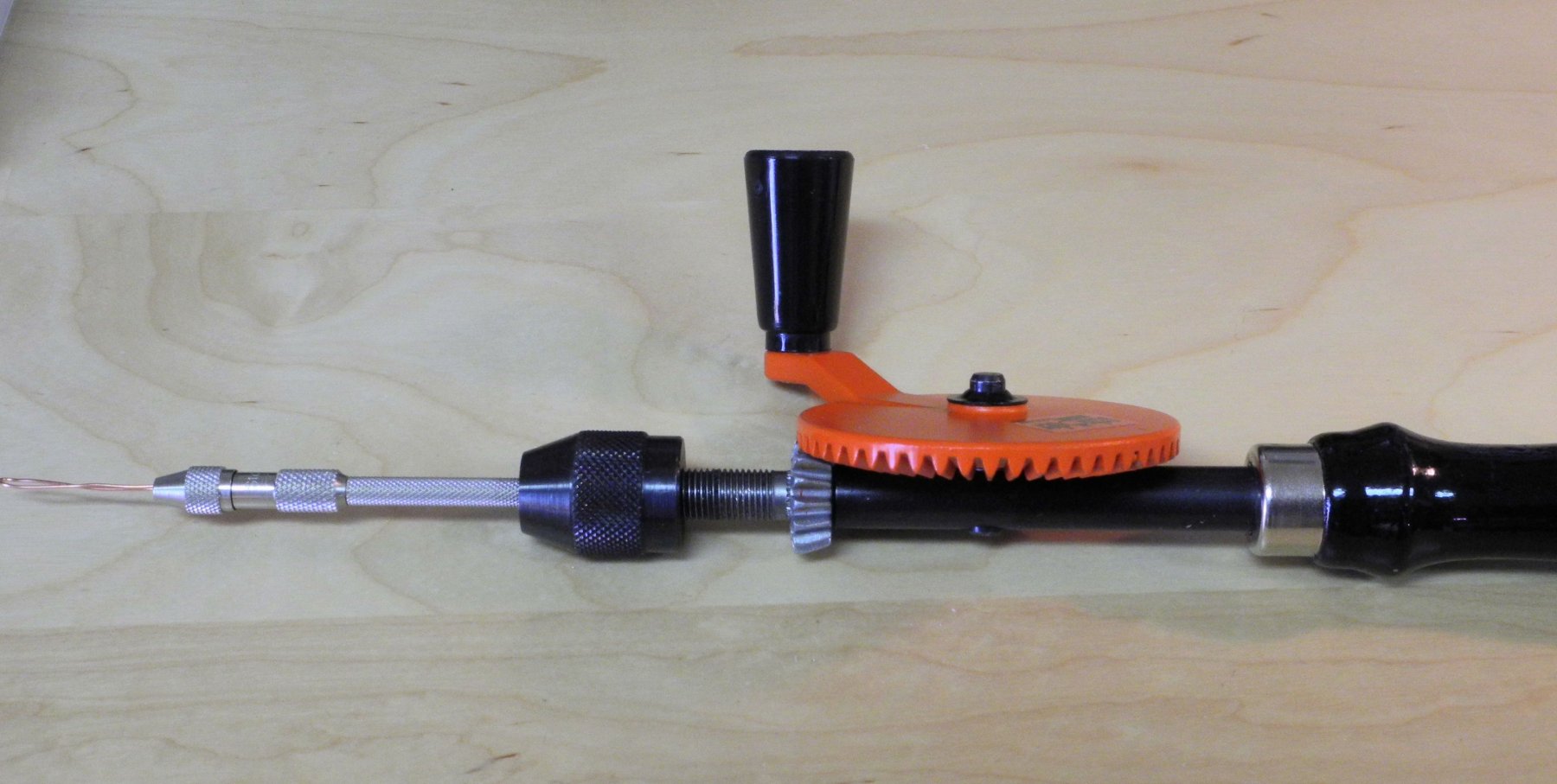
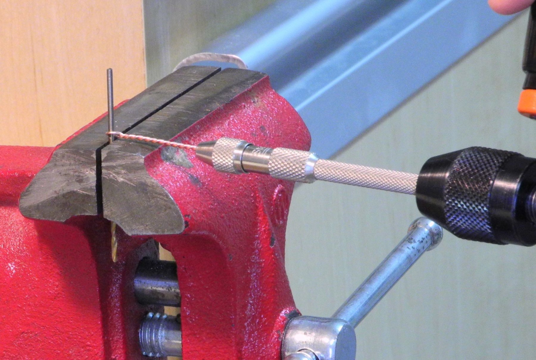
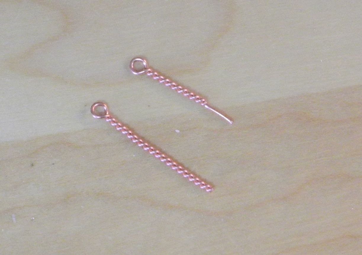
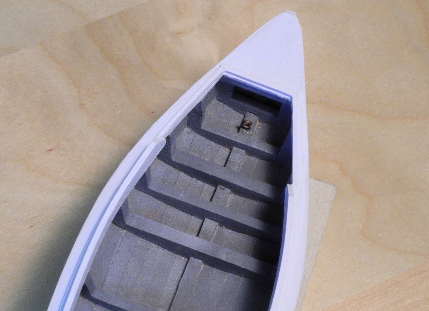
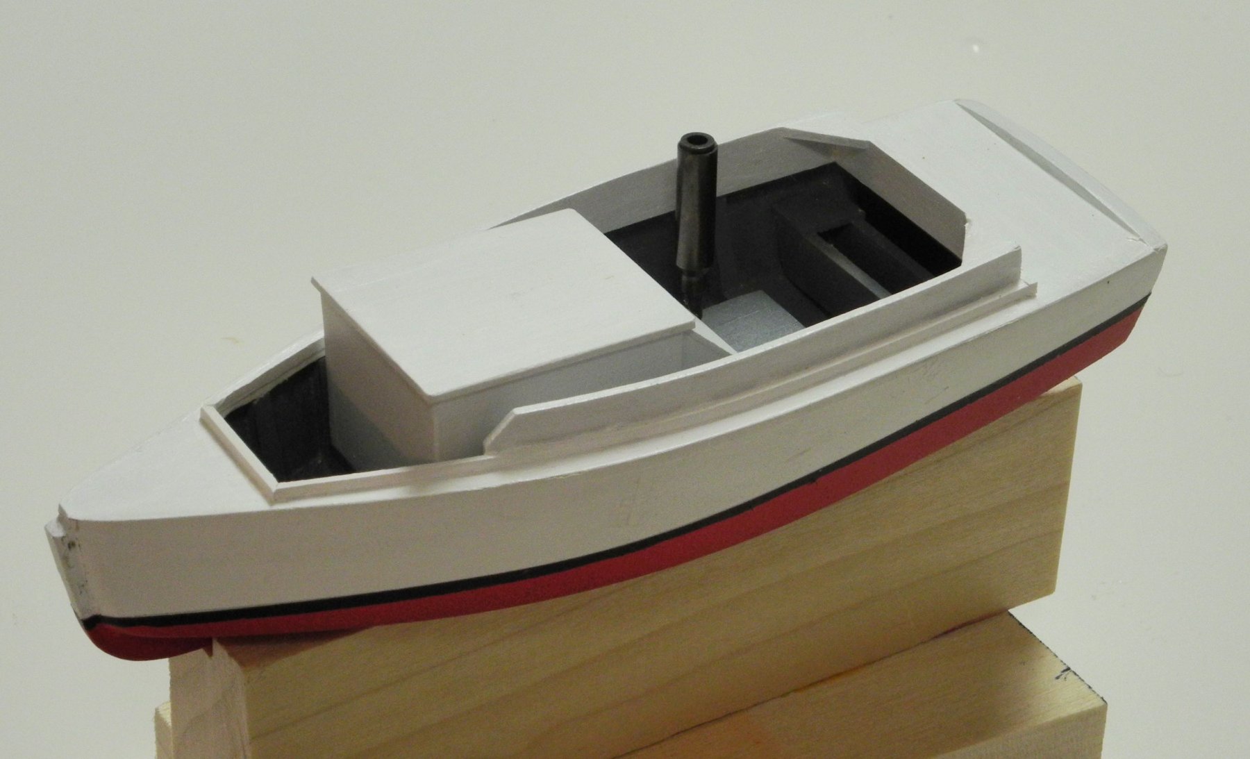
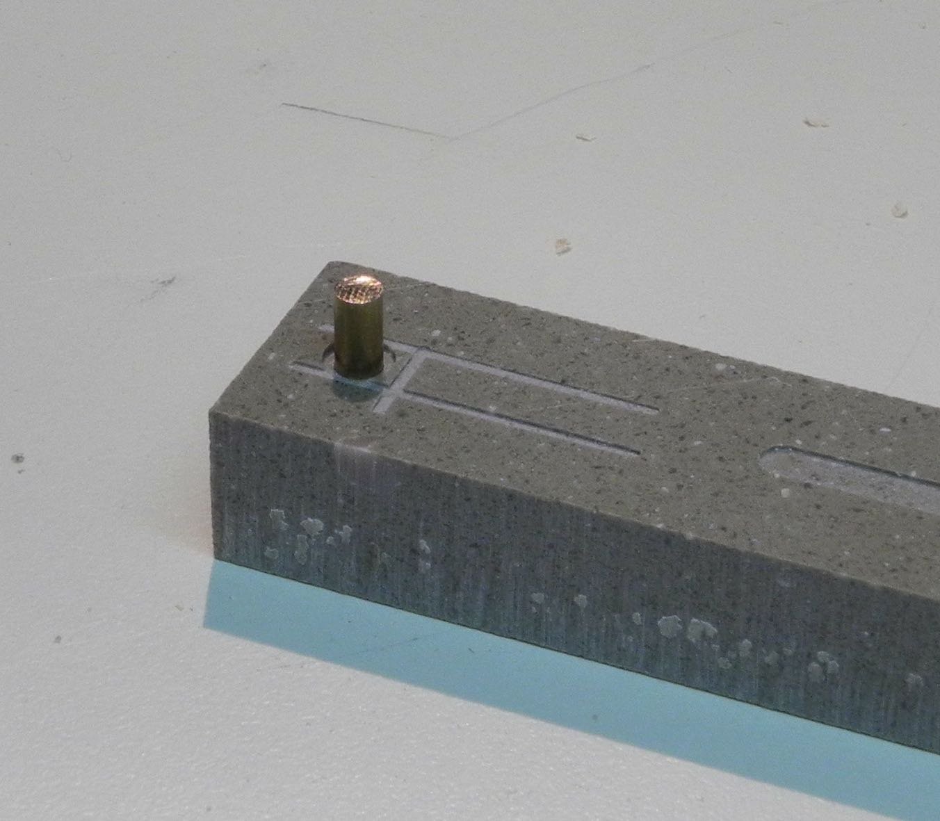
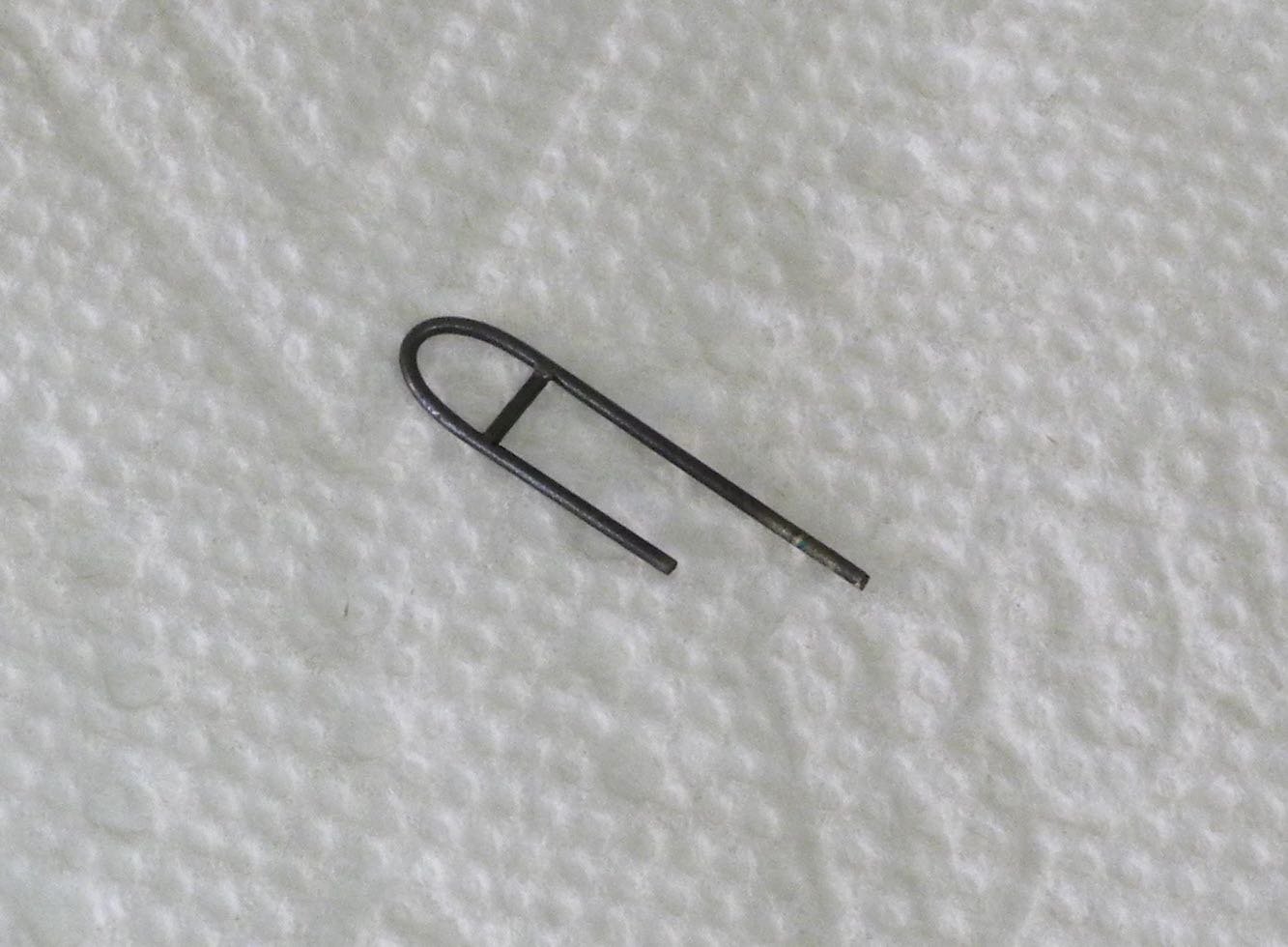
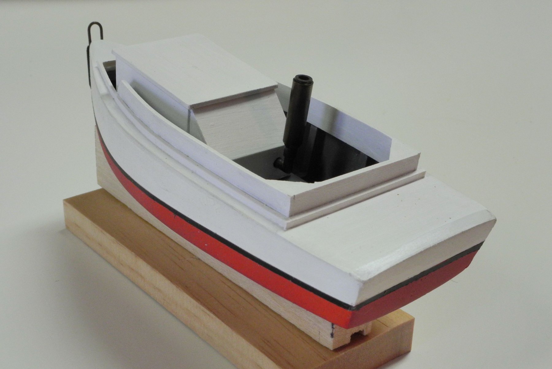
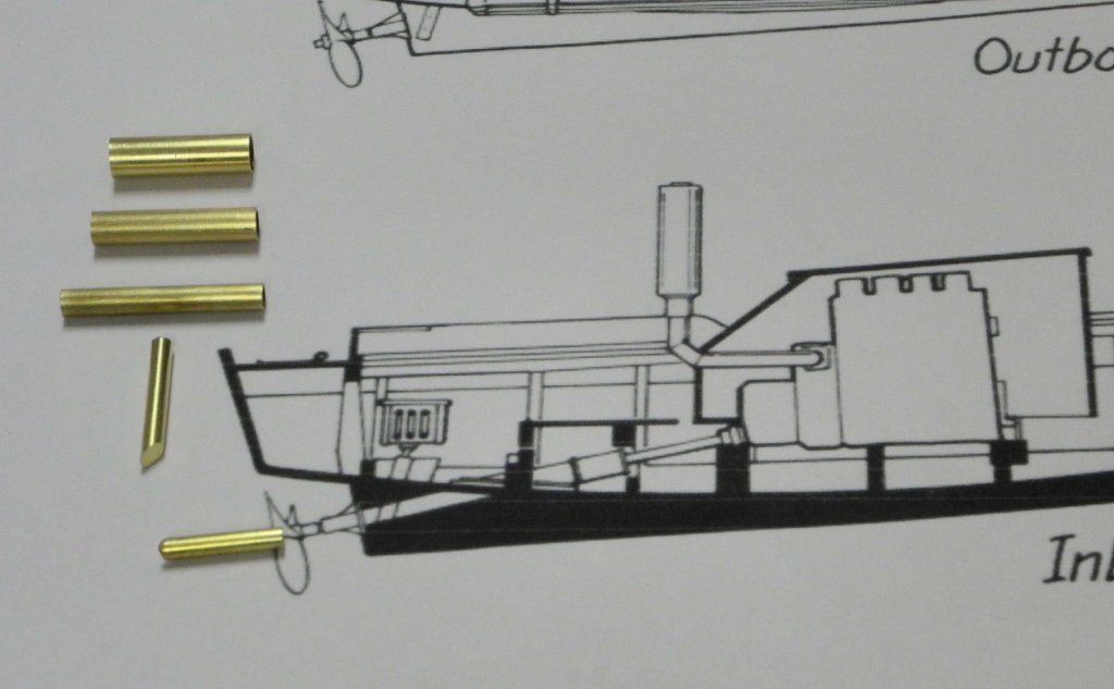
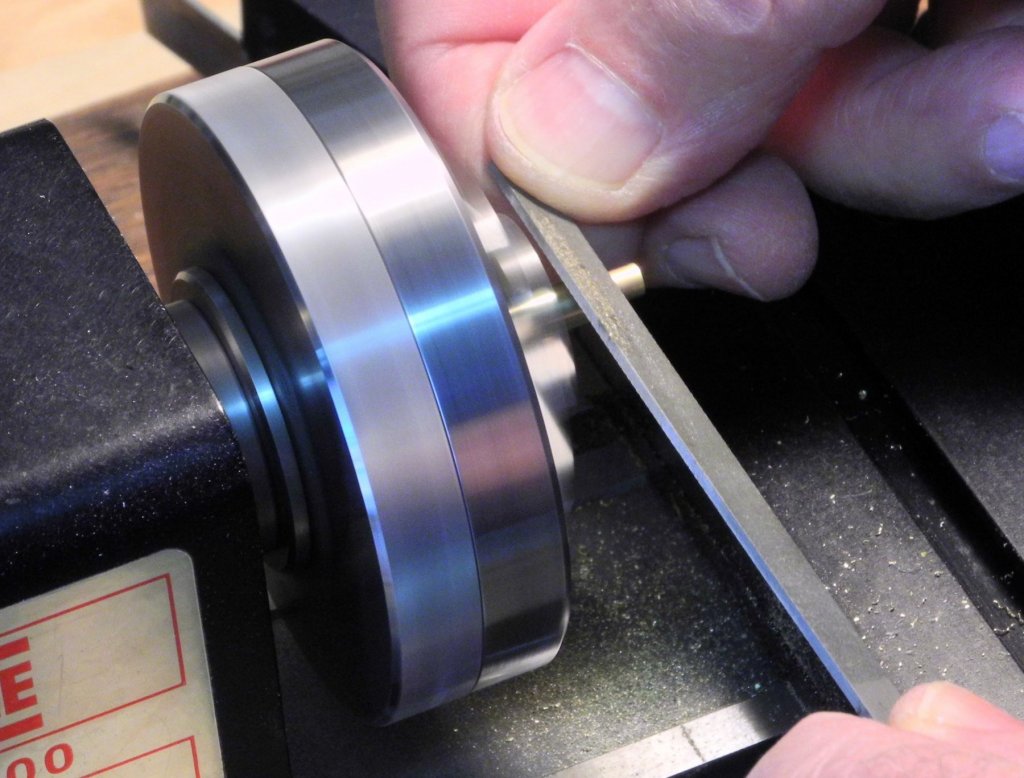
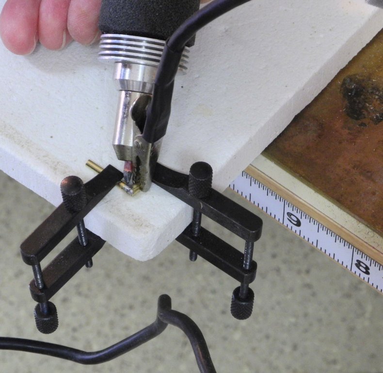
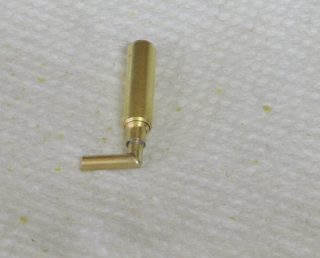
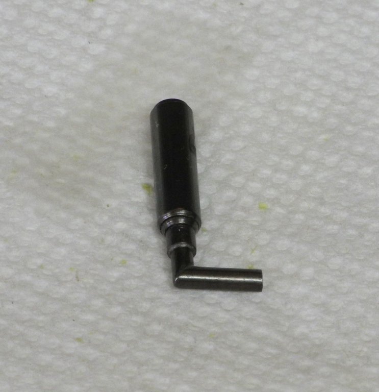
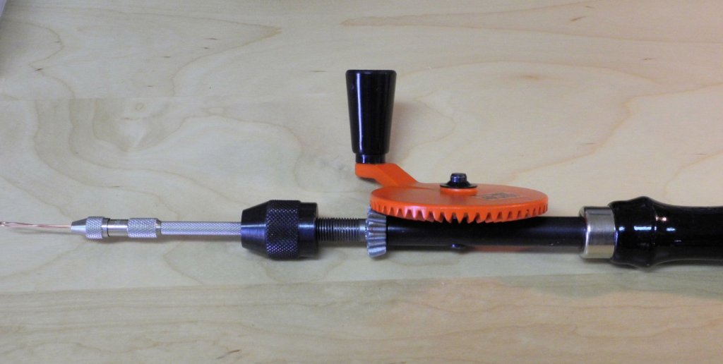
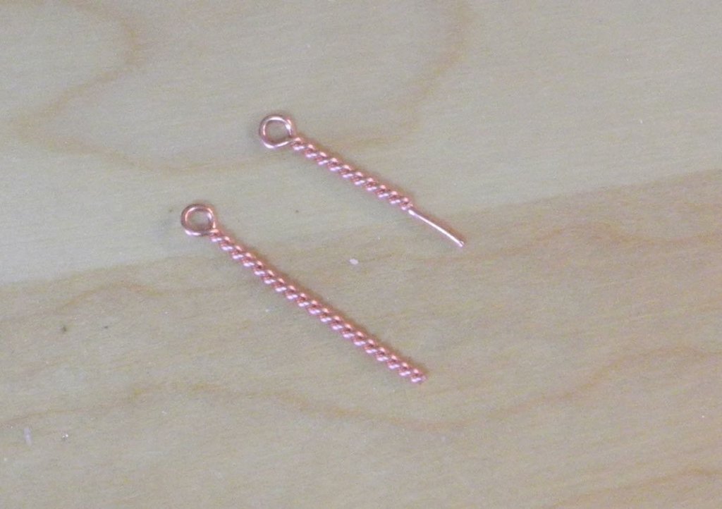
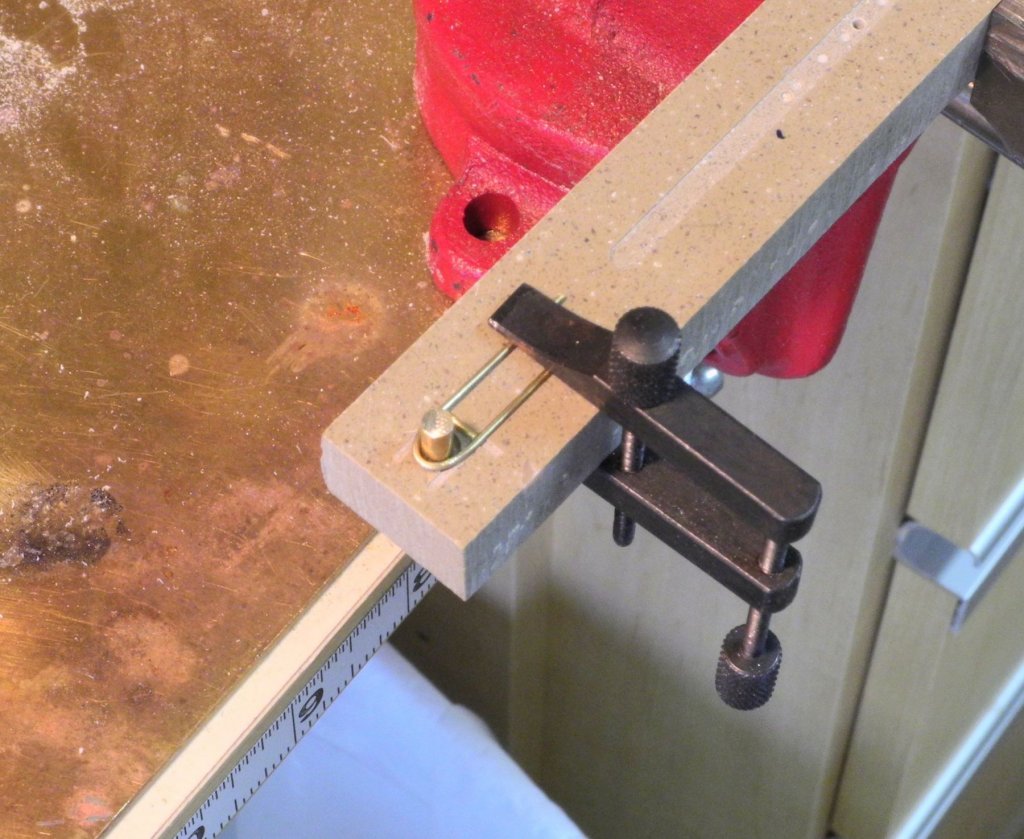
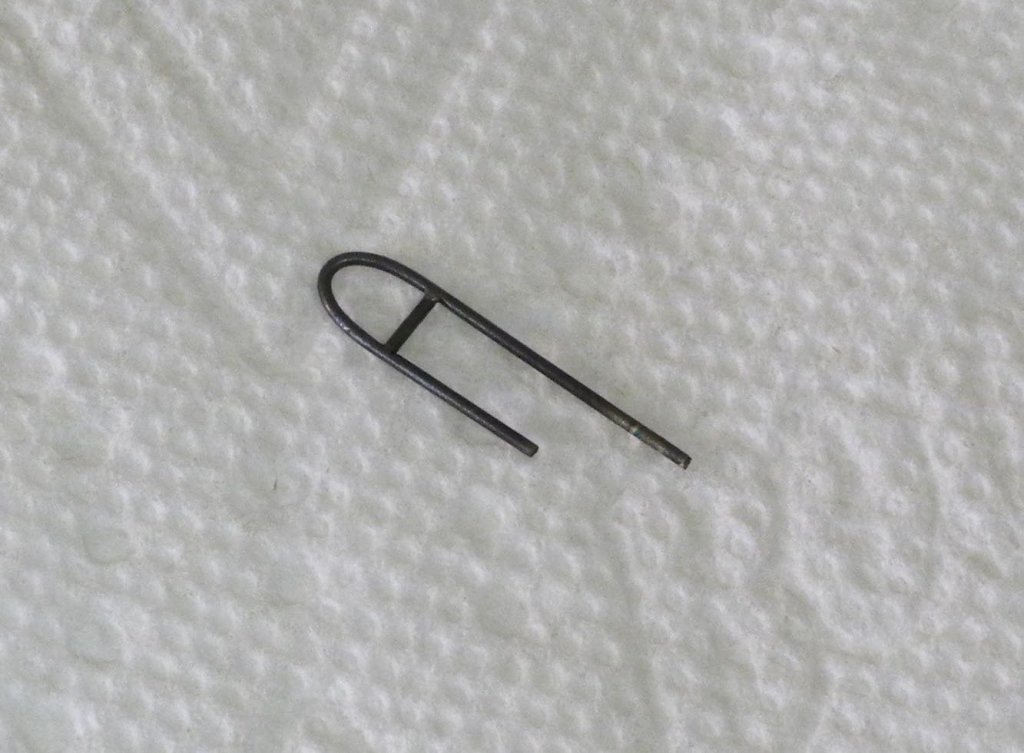
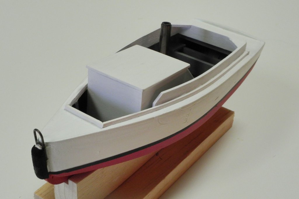
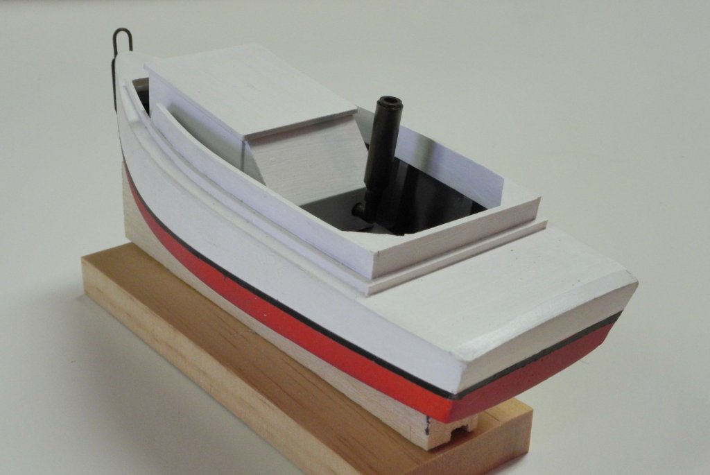
Part 40 – Yawl Boat cont’d The last post on the Yawl Boat showed the hull being built. The interior of the boat is mostly taken up by a Cummins 4 cal turbocharged diesel engine, covered by an engine housing with a vertical muffler/exhaust pipe. The exhaust pipe configuration was made from the pieces shown in the following photo: three telescoping pieces of brass tube forming the muffler, with pieces of solid brass rod forming the exhaust pipe coming our of the engine housing. The muffler was formed first, and the first step was to solder the three tubes together. Since there is a taper on the bottom of the muffler, the tubes needed to be different lengths. The soldered configuration was then chucked in the lathe and a hand file was used to form the taper. The pieces that form the exhaust pipe were soldered together and then soldered into the muffler. The configuration was blackened using JAX Warm Black. The engine housing was formed and painted, and the exhaust pipe/muffler combination was glued to the housing (using CA glue). Before the engine housing could be mounted in the boat, there were a couple of large ringbolts that needed to be installed inside the boat. These were formed of copper wire. The process for making the bolts uses a pin vise chucked into a hand drill. The pin vise allows the use of very small copper wire that would be difficult to hold in the larger chuck of the hand vise. An appropriate sized drill is held in the bench vise, the wire is looped over the drill bit, and then the hand drill is turned until the ringbolt is formed. This process results in identical ring bolts, and is very quick and simple. The following photo shows one of the bolts installed in the forward part of the yawl boat after the bolt had been blackened. The engine housing was then mounted in the yawl boat. The Yawl Boat has a metal ring configuration attached to the stem of the boat, presumably for securing the boat to the Skipjack’s transom when in use. This ring assembly required the use of a jig for forming and holding the ring configuration while soldering. The post is a 1/8” solid brass rod. The ring configuration is made of 1/32” brass rod, so the ring outside the brass rod was made with a 3/16 end mill and the grooves for the straight pieces were made using a .040” end mill. The 1/32” rod was annealed for bending around the 1/8” rod, and then the configuration was clamped in the jig for soldering the small crosspiece. After soldering the ring configuration was blackened. The legs were left long so that they could be properly fitted during installation. A bumper on the front of the Yawl Boat appears to be made from an old tire. This was simulated by shaping a piece of wood and then painting it without smoothing or sealing it. This was mounted to the stem along with the ring configuration. There are still a couple of items to be added to the Yawl Boat – some exterior trim (I’ll need to order some very small styrene half-round for this) and the boat’s propeller. I’ve never made a propeller before, but there are some very good examples in other build logs. This work will need to wait until I get back from our trip. I’ll be traveling for the next three weeks, so there will be no work on Kathryn until I return. During the trip I’ll be able to see Kathryn up close and hope to get more photos of the details that are still ahead of us. I’ll probably post some of those photos when appropriate. I’ll check in on MSW whenever we get good WIFI. Thanks everyone!


- 878 replies
-
- 21
-
-
Thanks Brian. I hope we're able to have a meeting after mid-October. Thanks Druxey. I struggled with the decision on how much of the deck to plank, but I keep going back to my original intent - to make both the construction and the appearance as authentic as possible. As you say, I have lots of photos to show what's hidden.
-
Thanks Carl, Popeye, Rich, and Patrick for the comments. And thanks to everyone for the 'Likes'. I've been off the site for a little while due to some family business taking lots of my time. I'll be posting one more update, then I'll be gone for most of the next three weeks on vacation.
-
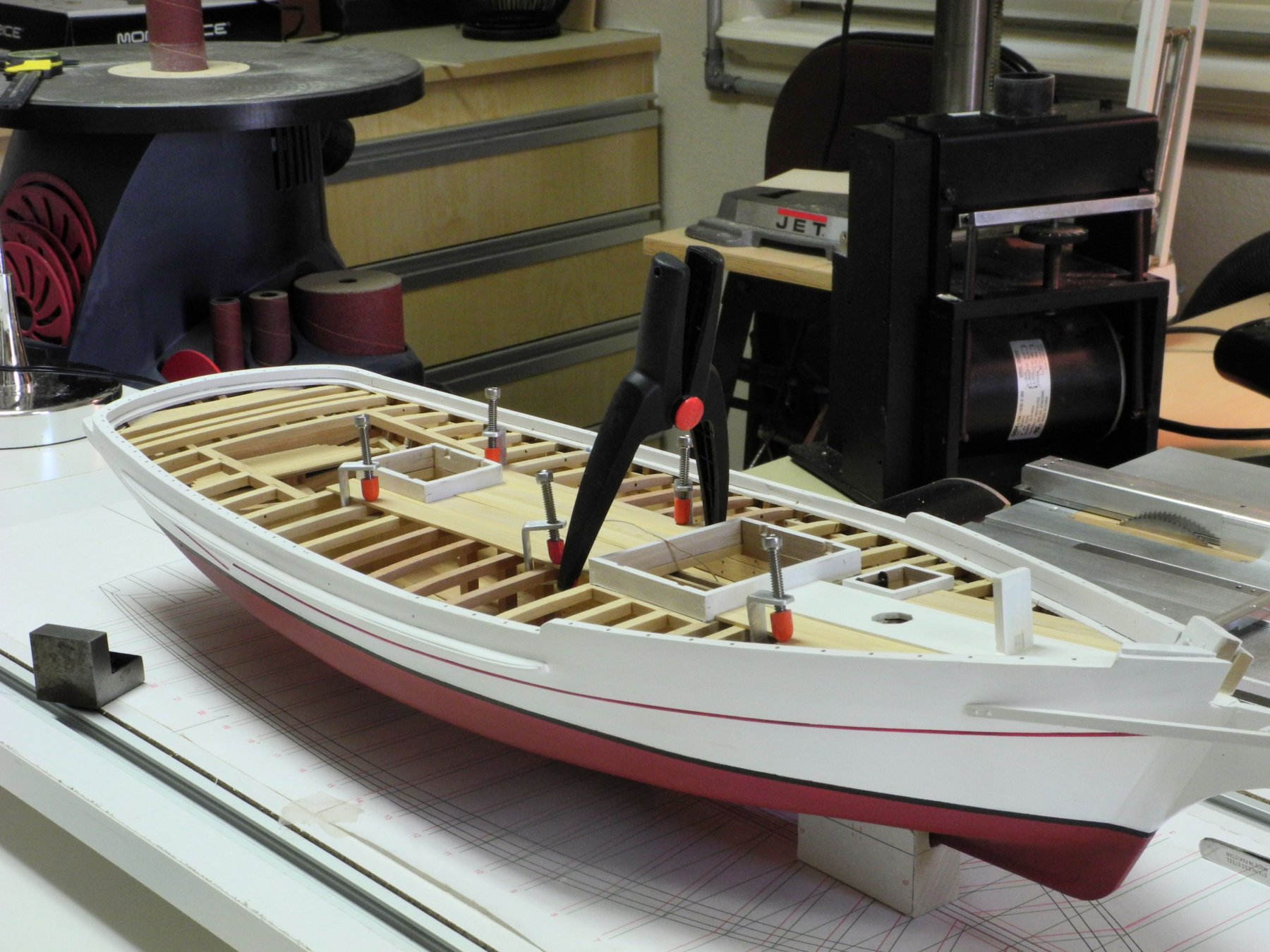
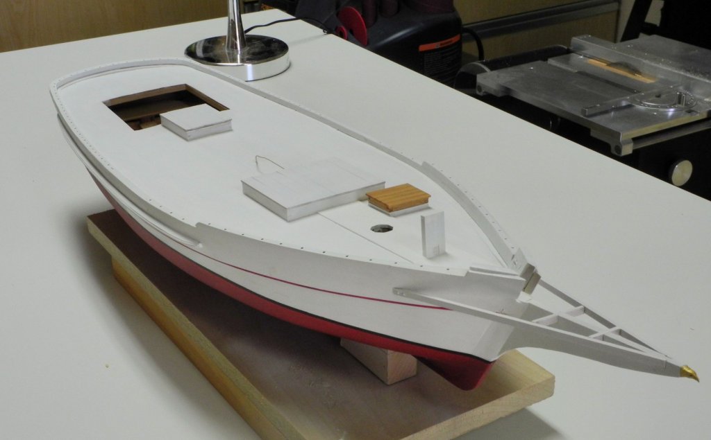
Part 39 – Deck Planks cont’d Thanks for all of the input. I admit that I agree with you for most builds, since I really like the look of natural wood. But since I had committed to make the model as close to the real Kathryn as possible I felt that the decks had to be painted, since that’s how she sits today. I started by masking all the openings (I used the mast stub to close off the hole for the mast), and then priming the deck. I used the white primer from Model Master, and applied it with a brush. I rubbed down the primer with very fine sanding sheets similar to Scotch Brite pads. Then I airbrushed the deck. Overspray that reached the previously painted parts (log rail, king plank, Sampson Post) wasn’t a problem. I used Liquitex Titanium White, mixed with an equal amount of Liquitex Matte Medium, and thinned with Liquitex Airbrush Medium. Liquitex acrylics tend to develop a sheen, and the Matte Medium keeps the paint relatively flat. The following photos show the finished deck. I’m glad I painted the deck – it’s looking more like the real Kathryn. I’ve almost finished the Yawl Boat, and that will be the subject of the next post.

- 878 replies
-
- 22
-
-
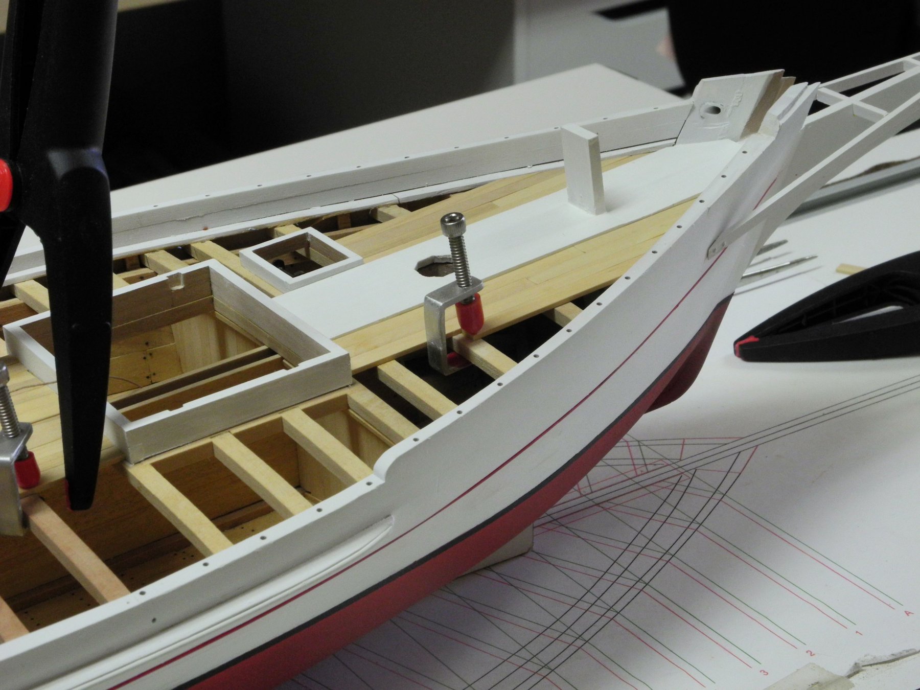
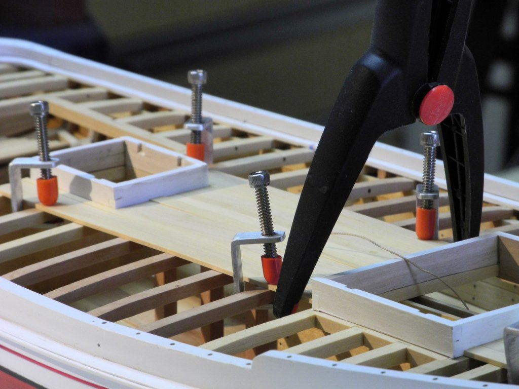
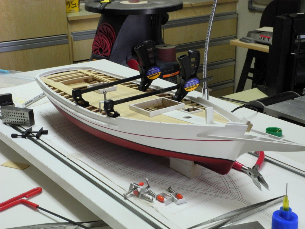
Part 38 – Deck Planks As I mentioned in the last post, I had decided to start installing the deck planks while I was building the yawl boat. Some decisions were needed for the deck planks. First, should some planks be left off to show all of the interior construction of the model? And second, should the planks be left natural or painted white? Kathryn’s deck is painted white, even though the paint is pretty roughed up during oystering season. All along, my goal with the model is to have the model look as close as possible to the real Kathryn. So this actually was the answer to both questions: the model would have a full deck, and the deck would be painted white. The interior construction would only be visible through the hatches, since the hatch covers are removable. Planking was started amidships, and the first planks were laid along the centerline. Small homemade C clamps were used to clamp the deck planks to the beams, and clamps were used to ensure that the planks were tight to each other. The bow area required a lot of fitting, since none of the deck planks are nibbed. As planking progressed, different clamps were needed to keep the planks tight together. Since the deck would be painted it wasn’t necessary to install any simulated fasteners or caulking, so planking moved along fairly quickly. Kathryn now has a full deck and is waiting for the deck to be painted. I’ll feel a little bad covering up that beautiful castello. Work is progressing on the yawl boat, and I hope to be able to show its completion in the next day or so.


- 878 replies
-
- 23
-
-
Great work, as usual, Ed. I like the modified alligator clip - have to remember it.
- 3,618 replies
-
- 3
-
-
- young america
- clipper
- (and 1 more)
-
Looks like a really interesting subject, Ken. I'll be following along.
-
Hi Elia: I totally agree. I ordered this supplement after you told me about it during your recent visit, and it's everything you said. Now I'm confident I'll be able to make the sails for Kathryn when I reach that point (in the distant future).
-
Hi Elia: Gluing the frames in tight quarters was a little bit of challenge, but as long as I was able to use the machinist squares to stabilize them while the glue set they came out OK (but not perfect). I used grey for the interior because I had no reference photos that showed the interior color. I'm sure the yawl boat interior gets beat up pretty well during the oystering season (as the rest of Kathryn does) so I thought it was a practical color. I'll probably find out if I'm far off in color when I visit Kathryn next month, so we'll have to wait till then. Good to hear from you.
-
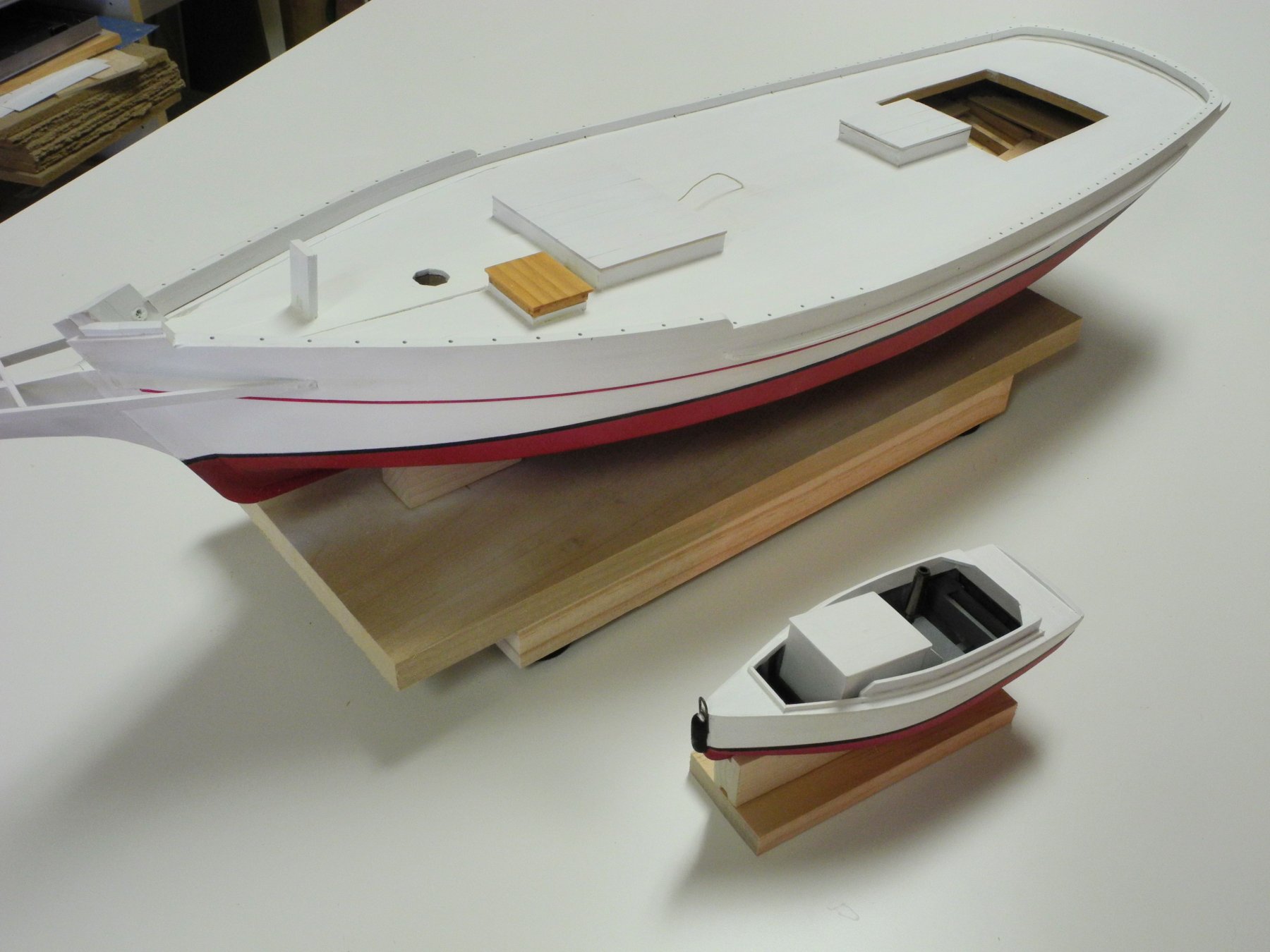
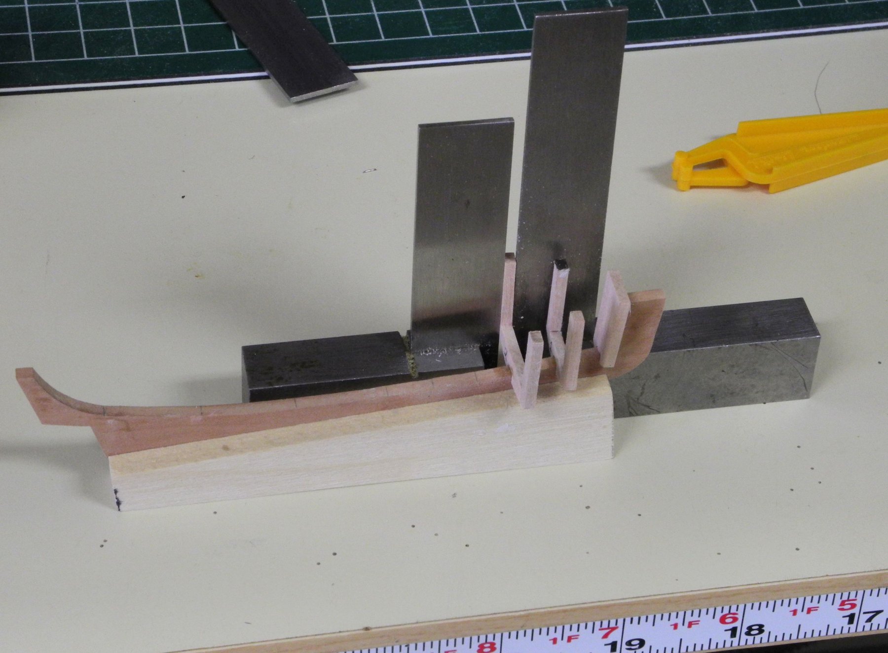
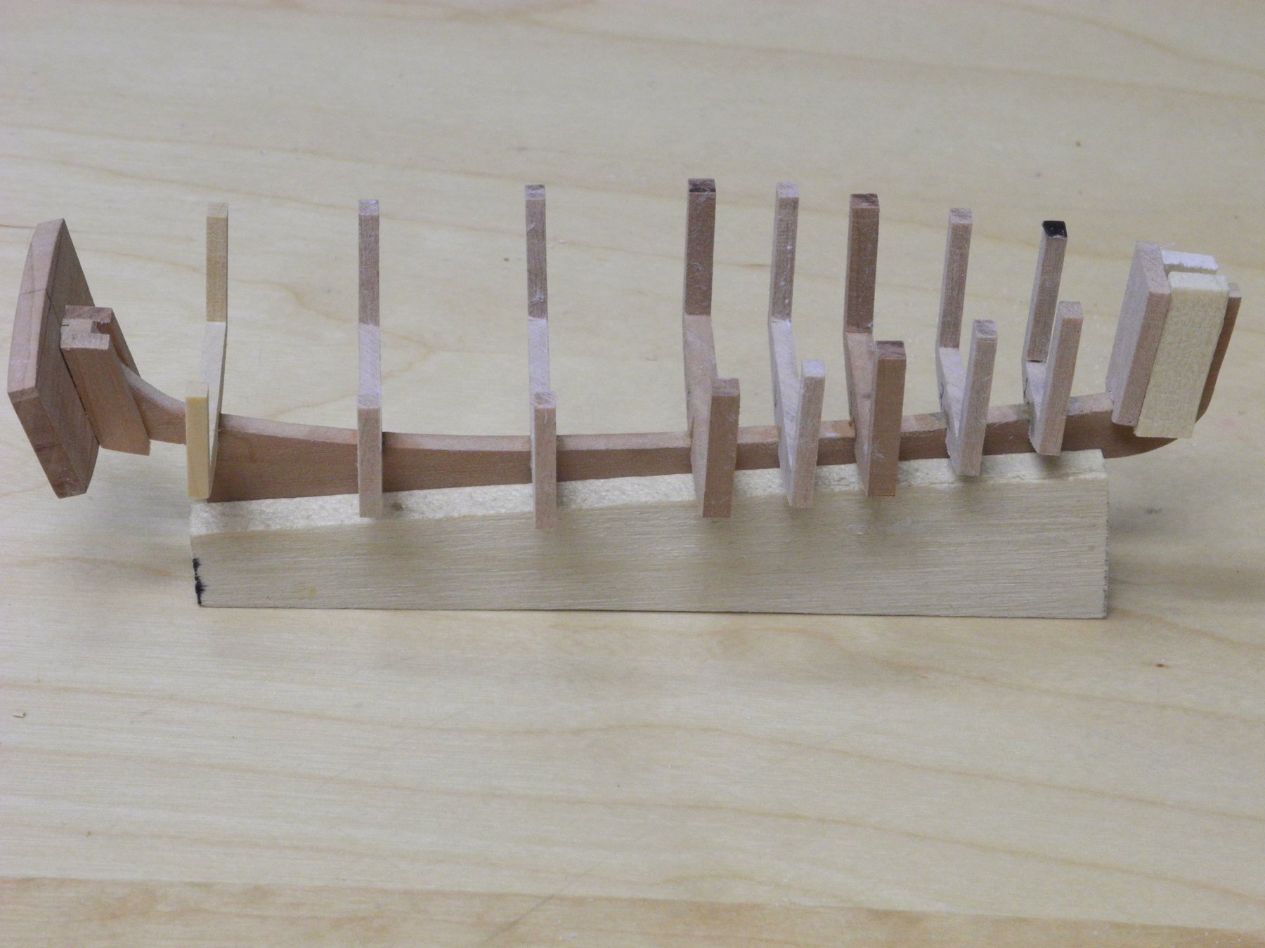
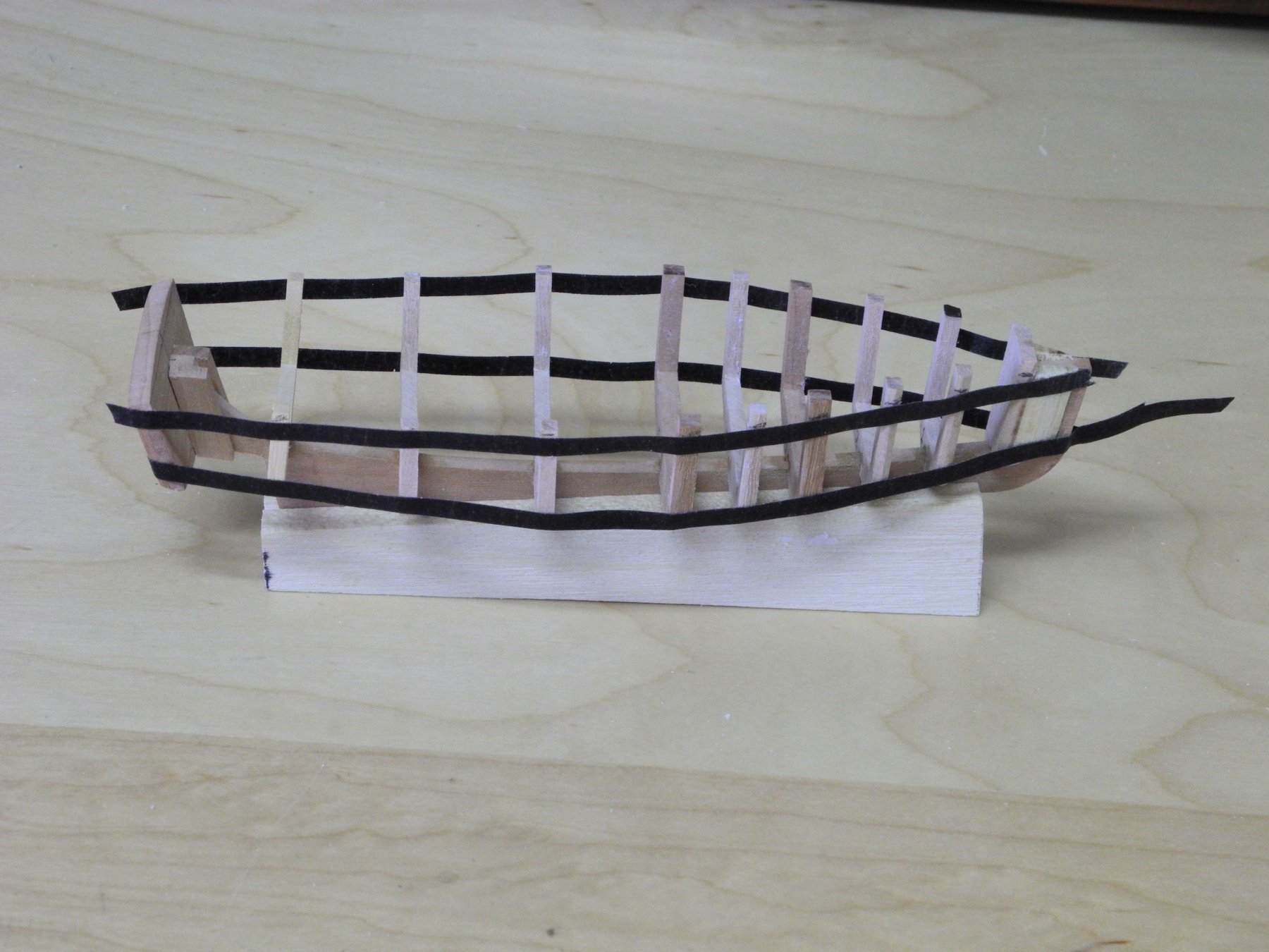
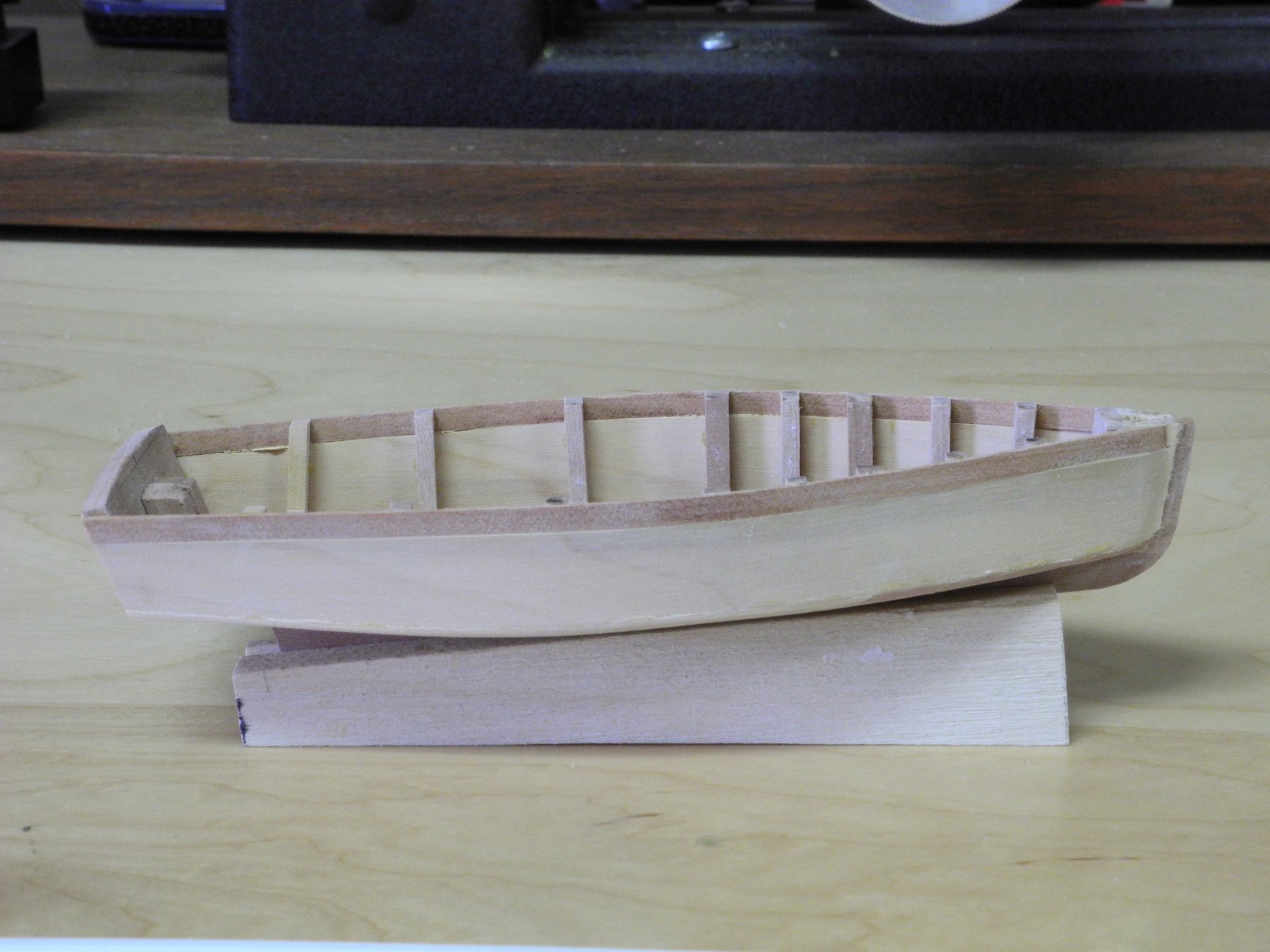
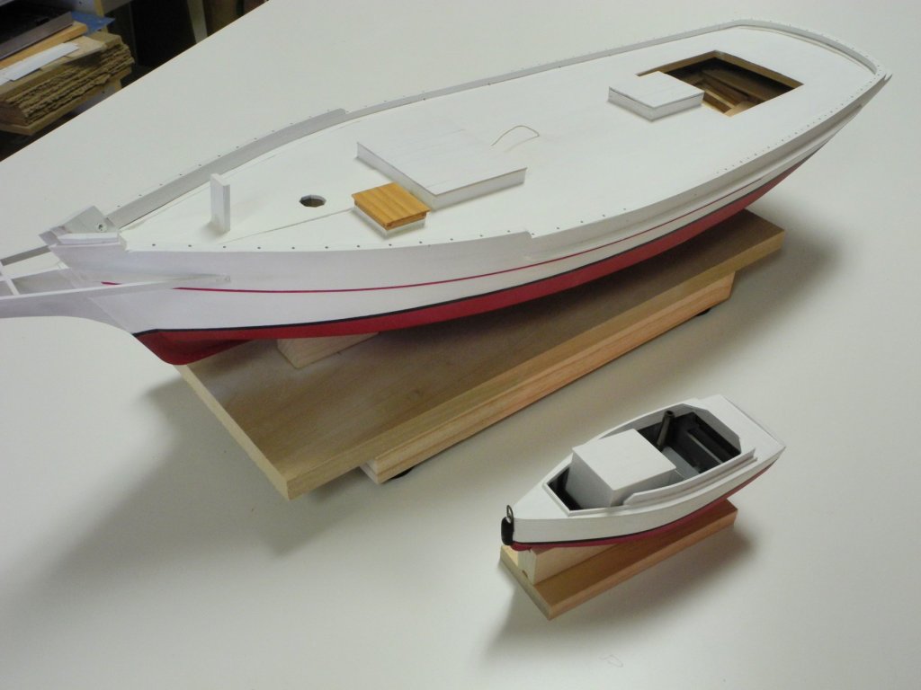
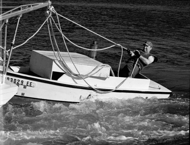
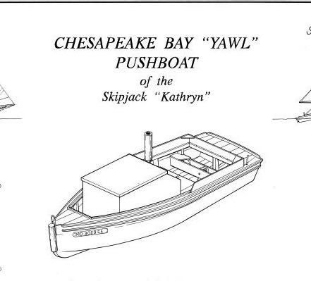
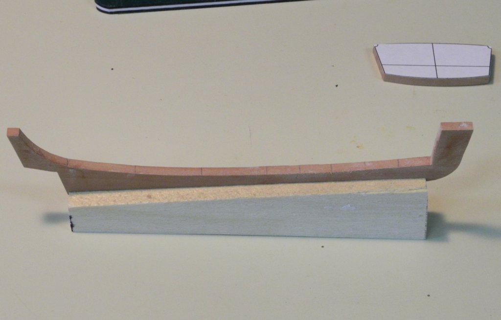
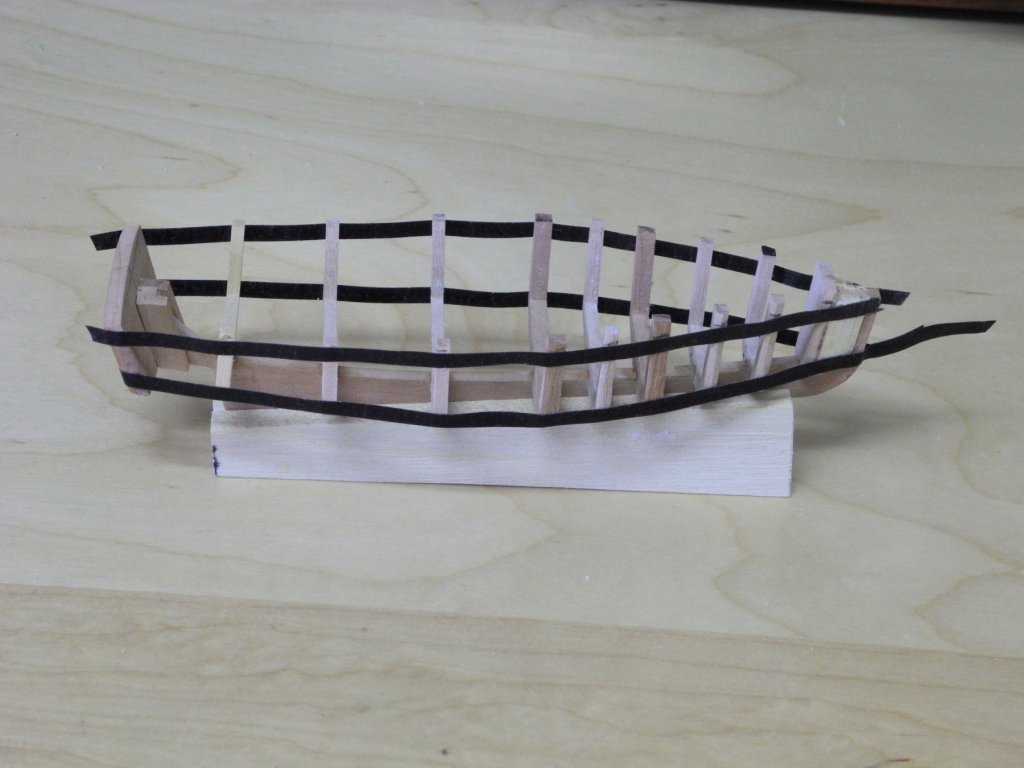
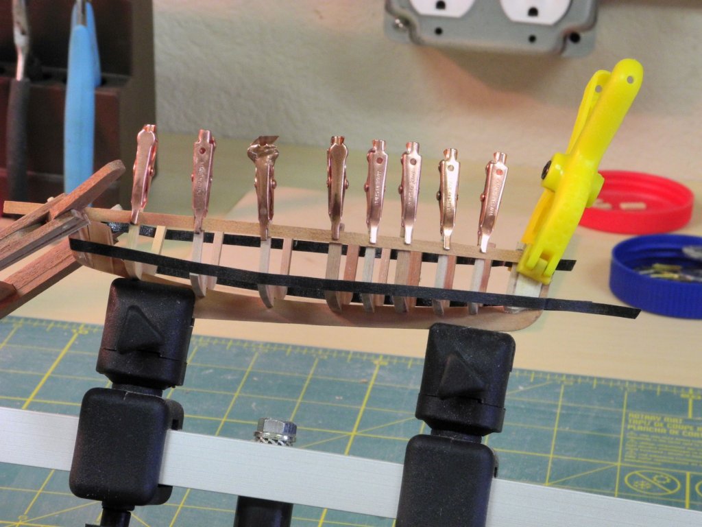
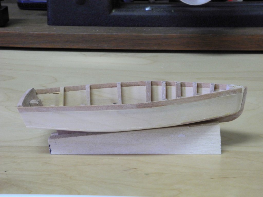
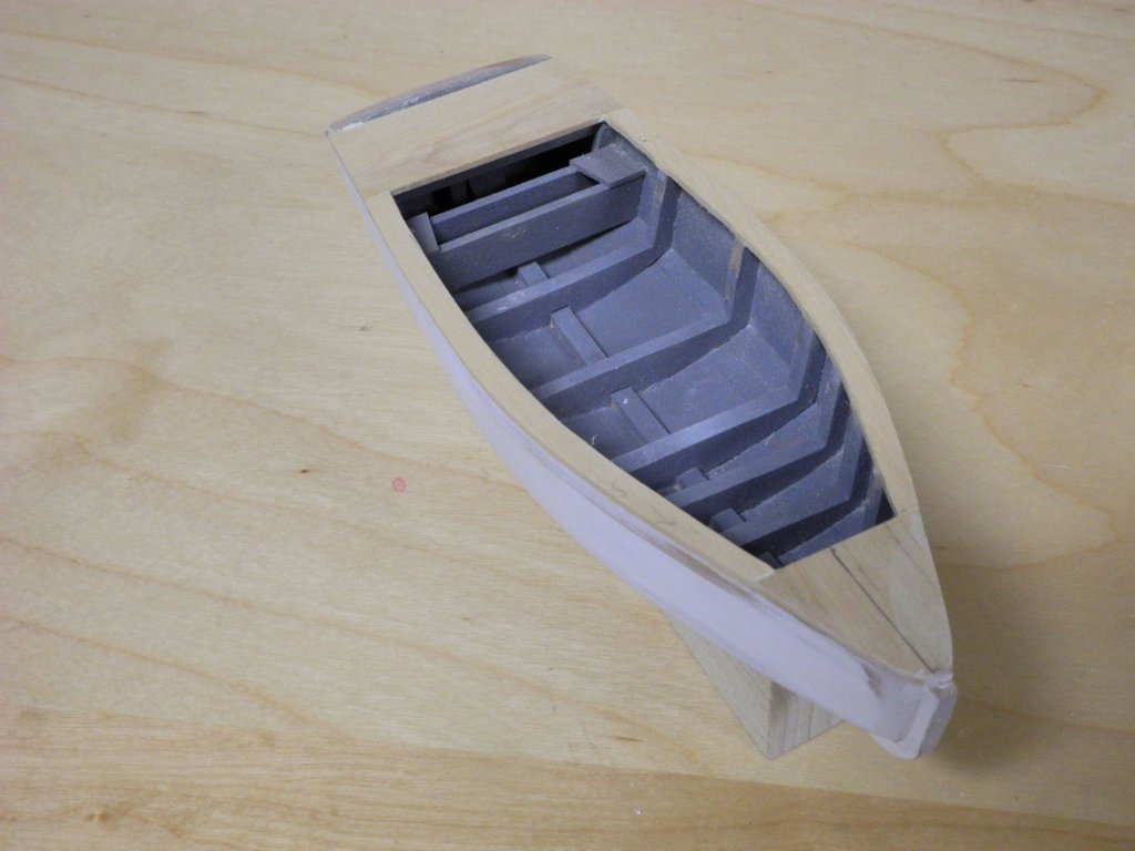
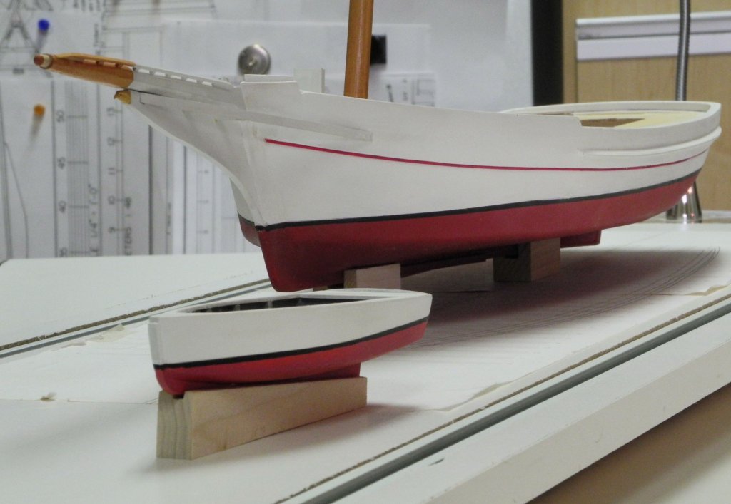
Part 37 – Yawl Boat Laws governing oystering in the state of Maryland have restricted dredging to sail-only for many years. Recently however, the shortage of oysters and the difficulty in getting enough crew to man the oyster dredging boats 7 days a week has caused the state to relax the laws so that dredging can be done using the push boat (called a yawl boat in the Chesapeake) for power dredging 2 days a week. This has resulted in most dredging boats only going out during their permitted 2 days. The book “Working Skipjacks of Deal Island” by Brice Stump has some great photos of the yawl boat and its operator at work. The following photo is from the book: The operator is helping the Kathryn’s captain maneuver the skipjack by pulling on the ropes on one side of the davit. The configuration of the engine cover in this photo is different from the drawings in the HAER documentation. Obviously the yawl boat has been modified over the years, but since the model is based on the HAER documents that reflect how Kathryn was configured in the mid-1990’s, the yawl boat for the model will be built as it was in that timeframe. The HAER documentation contains line plans for the yawl boat, so these drawings were used to develop the keel and frames for the model yawl boat. The model frames are somewhat thicker than the real frames would be, but these frames would not be obvious in the model and the extra thickness provides some strength to support the planking. A holding device (a simple block of wood tapered at the correct angle and with a 1/8” groove milled in it) was made to hold the keel at the proper angle during assembly – this allows the frames to be set vertically. The frames were held during gluing by using two machinist squares. Given the small size of the yawl boat I didn’t think it made sense to try to replicate the jigs I used in the installation of Kathryn’s frames. The rearmost frame is not absolutely vertical, but I didn’t think this would be a major issue. When all of the frames were in place, chart tape was used to line off the sheer and the chine. Using the resulting drawn lines, the sheer plank was installed on each side, and the tops of the frames were trimmed to the top of the plank. The side planking is 1/32” thick. The sheer plank was made from 1/8” wide piece of madrone. Since the sides of the yawl boat are straight, the rest of the side planking was made from a single piece of 1/32” castello that was spiled on top and bottom. There is a ‘locker’ at the aft of the cockpit, which will house one of the large blocks used to raise and lower the yawl boat. This was added to the model, and the interior of the yawl boat was then painted a workmanlike grey. The exterior colors of the yawl boat mimic Kathryn’s color scheme, so the hull was painted next. The superstructure of the yawl boat still needs to be built. This will include an exhaust pipe for the boat’s diesel engine, and will be the subject of a future post. In the intervals between each step of Yawl Boat construction I decided to install Kathryn’s deck planks. This will be the topic for the next post.


- 878 replies
-
- 23
-
-
Thanks Russ. Even though this is a very forgiving scale at 1:32 there are still some small items to deal with - many more to come when I get to the iron work. Thanks Rich. I find that using Sculpy for small 'carvings' is much easier than trying to carve them from wood.
-
Nice work, Rich. If you have trouble making working hinges you could make simulated hinges and leave the door of one side open to show the one-holer.
- 1,135 replies
-
- 5
-
-
- model shipways
- syren
- (and 2 more)