
Supplies of the Ship Modeler's Handbook are running out. Get your copy NOW before they are gone! Click on photo to order.
×


Mahuna
-
Posts
1,501 -
Joined
-
Last visited
Reputation Activity
-

 Mahuna got a reaction from Calhoun Zabel in Kathryn by Mahuna - FINISHED - 1:32 - Skipjack Based on HAER Drawings
Part 51 – Kathryn’s Dredge Winder Cont’d
It has been quite a while since my last post. Here in Arizona, February and March are very popular months for visitors, and we had our share this year. So time in the shop has been hard to get for the past 6 weeks or so. I did mange to get a little done, and the last few days have been fairly productive.
The last photos showed the winder completed but still not blackened. The next photos show it after blackening (yes, I thought about leaving the brass natural, but I want to show Kathryn as she actually looks, so I needed to blacken the winder).
The dredges are hauled on cables, but metal cables would be difficult to wind around the winder drums, so black rope was used on the model instead. After winding the rope around the drums, matte medium was painted on the rope to keep it from loosening.
The frame around the dredge winder is constructed from angle iron. There is 1/16 and 1/8 brass angle iron available, but neither size was appropriate (I needed 3/32). So 1/32 was milled off each side of the 1/8 angle iron using the setup shown in the following photo.
The silver-colored clamps are homemade clamps that provide additional reach over the standard Sherline clamps.
The ends of the frame are constructed with angles rather than straight, and the ends are canted inward, as in the following construction drawing.
A wooden form was made to support the construction of the winder frame.
The angle on each side of the end pieces is 130 degrees, so the disk sander miter gauge was set at 65 degrees and the ends of the angle irons were sanded to this angle.
The end pieces of the form were removable to allow for clamping of the pieces.
Although the form is wood, it was able to withstand the resistance soldering which localizes the heat. This setup probably wouldn’t work very well for soldering with a torch.
Once the individual sides of the ends were soldered, the complete form was used to join all of the pieces to the crossbar.
In the above photo, a small hand vise is holding the form, and this small vise is being held in the bench vise.
The basic frame was completed, but still needed the cross-braces.
The soldering of the cross-braces required some extra effort to keep from opening the joints already soldered. Pieces of paper towel that had been soaked in water were clamped around existing joints to prevent the heat from opening those joints.
The following photos show the winder frame completed and blackened and temporarily in place. Additional work on the blackening is still needed.
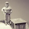
Here’s a photo of Kathryn’s real winder and frame.
The pulleys hanging from the crossbar still need to be made, as well as the boards that are beneath the I-beams. The housing for the engine that drives the winder also needs to be made. The winder configuration will then be put aside until later in the project so it doesn’t interfere with other delicate construction work.
Thanks everyone. I hope to post more frequently now that work is again under way.
-
Mahuna got a reaction from Calhoun Zabel in Kathryn by Mahuna - FINISHED - 1:32 - Skipjack Based on HAER Drawings
Part 52 – Kathryn’s Dredge Winder Cont’d
There are two pulleys hanging off either end of the dredge winder’s crossbar. The shape of these pulleys is fairly unique, so available blocks couldn’t be used and they needed to be fabricated. The following drawing shows the shape of these pulleys.
I tried making these out of brass, but the small size presented lots of problems so I decided to make them out of wood. The first step was gluing the drawing to an appropriately sized piece of wood.
The holes representing the size of the sheaves were drilled.
Then the outline of the pulley was shaped, first by cutting on the scroll saw and then by finishing with small files.
The groove representing the outside of the sheave was made using a small round escapement file.
A hole was drilled in the top of the pulley and a small ring made from copper wire was inserted and glued using CA.
The pulleys were hardened by soaking with thin CA, and were then finish-sanded. Black Rust-Oleum paint was sprayed on the pulleys while they were held by thin wire.
The pulleys were attached to the crossbar using small rings made from black wire.
The I-beams supporting Kathryn’s dredge winder are themselves supported by some wooden planks. On the model, these planks were drilled and then small pieces of .019 piano wire were glued into the holes to act as pegs for attaching the winder configuration to the model’s deck.
The planks with pegs were epoxied to the bottom of the I-beams. The blackening was scraped off the I-beams to ensure that the epoxy would hold.
Holes were drilled into the model’s deck to take the pegs. The following photo shows the winder configuration pegged to the deck, with the ‘cables’ for the dredge winders fed through the new pulleys.
The dredge winder is powered by a V-6 Buick engine contained in an engine housing. The following photos show the model’s engine housing in place. The exhaust pipe was made from 1/8” brass tubing colored with JAX Flemish Black diluted 1:1.
The dredge winder assembly will not be permanently mounted on the model until somewhat later in the build. Here are some photos of Kathryn’s current state.
There are a number of small items to be completed next, while I spend some time planning for the rest of the build.
Thanks everyone!
-
 Mahuna got a reaction from PeteB in Kathryn by Mahuna - FINISHED - 1:32 - Skipjack Based on HAER Drawings
Part 52 – Kathryn’s Dredge Winder Cont’d
There are two pulleys hanging off either end of the dredge winder’s crossbar. The shape of these pulleys is fairly unique, so available blocks couldn’t be used and they needed to be fabricated. The following drawing shows the shape of these pulleys.
I tried making these out of brass, but the small size presented lots of problems so I decided to make them out of wood. The first step was gluing the drawing to an appropriately sized piece of wood.
The holes representing the size of the sheaves were drilled.
Then the outline of the pulley was shaped, first by cutting on the scroll saw and then by finishing with small files.
The groove representing the outside of the sheave was made using a small round escapement file.
A hole was drilled in the top of the pulley and a small ring made from copper wire was inserted and glued using CA.
The pulleys were hardened by soaking with thin CA, and were then finish-sanded. Black Rust-Oleum paint was sprayed on the pulleys while they were held by thin wire.
The pulleys were attached to the crossbar using small rings made from black wire.
The I-beams supporting Kathryn’s dredge winder are themselves supported by some wooden planks. On the model, these planks were drilled and then small pieces of .019 piano wire were glued into the holes to act as pegs for attaching the winder configuration to the model’s deck.
The planks with pegs were epoxied to the bottom of the I-beams. The blackening was scraped off the I-beams to ensure that the epoxy would hold.
Holes were drilled into the model’s deck to take the pegs. The following photo shows the winder configuration pegged to the deck, with the ‘cables’ for the dredge winders fed through the new pulleys.
The dredge winder is powered by a V-6 Buick engine contained in an engine housing. The following photos show the model’s engine housing in place. The exhaust pipe was made from 1/8” brass tubing colored with JAX Flemish Black diluted 1:1.
The dredge winder assembly will not be permanently mounted on the model until somewhat later in the build. Here are some photos of Kathryn’s current state.
There are a number of small items to be completed next, while I spend some time planning for the rest of the build.
Thanks everyone!
-
Mahuna got a reaction from PeteB in Kathryn by Mahuna - FINISHED - 1:32 - Skipjack Based on HAER Drawings
Thanks everyone for the likes and comments.
Ed - I use 62/36/2 Silver-Bearing Solder from Radio Shack. It's .015" diameter wire, so I can cut very small pieces. I also use Stay-Clean liquid flux.
The blackening of the winder was done with JAX Chemical's 'Pewter Black'. Most of the other metal components will be blackened with their "Brown Black" product, which gives a warmer black and won't be as stark. In the photos of Kathryn (and in real life) the blackness of the winder is striking, while the other components not so much. The winder was painted with Rust-Oleum gloss black the last time I saw it. I used the JAX Flemish Grey-Black, very diluted, on Kathryn's wheel and will likely use that in some diluted form where appropriate.
Patrick - thanks for the compliments, but the super-miniature work you do is already outstanding - so your skills and talent are already 110%!
-
 Mahuna got a reaction from popeye the sailor in SHADOW by Omega1234 - FINISHED - Scale 1/300 - Luxury 60m Mega Yacht
That's another radical design! I'll be interested to see how you pull off the forward railing at your scale.
-
 Mahuna reacted to Omega1234 in SHADOW by Omega1234 - FINISHED - Scale 1/300 - Luxury 60m Mega Yacht
Hi Frank. Thanks, as always. I had a special little chuckle about your 'garden' comment. I needed a good laugh after a day like today! The answer is 1:1
Thanks Piet! Great to hear from you. Shadow's almost done, and soon, I'll be able to start my new project. Hint: She's really out of left field: Take a peek:https://yachtharbour.com/yacht/khalilah-2968.
How the hell am I gonna tackle this one! I've got a headache already!!!!!!!
Cheers
Patrick
-
Mahuna reacted to Aleksei Domanov in VR 3.1 Rope making machine
Dear friends,
I proud to present next version of rope making machine (video to come soon):
https://shipworkshop.com/products/tools/vr-31-rope-making-machine
VR 3.1 Rope making machine
(HD adaptable rope making machine. Former Ropewalk "Prosak")
What's new:
VR = Vertical ropewalk. New version of former ropewalk "Prosak". No need to reassemble for 3- or 4-stranded ropes. Can be secured on both horizontal and vertical surfaces. HD adaptable. Can be transformed into HD (Horizontal Design) machine. Not yet available. There are notches on the machine that will help to mark screw holes for securing the machine.
Here is user's manual:
VR31.pdf
-
Mahuna got a reaction from popeye the sailor in SHADOW by Omega1234 - FINISHED - Scale 1/300 - Luxury 60m Mega Yacht
Hi Patrick
I’m continually amazed at how much detail you can get into a tiny space. The little tender is awesome. (And I’m sure your garden is equally impressive - what scale is it?). 😉
-
Mahuna got a reaction from PeteB in Kathryn by Mahuna - FINISHED - 1:32 - Skipjack Based on HAER Drawings
Part 51 – Kathryn’s Dredge Winder Cont’d
It has been quite a while since my last post. Here in Arizona, February and March are very popular months for visitors, and we had our share this year. So time in the shop has been hard to get for the past 6 weeks or so. I did mange to get a little done, and the last few days have been fairly productive.
The last photos showed the winder completed but still not blackened. The next photos show it after blackening (yes, I thought about leaving the brass natural, but I want to show Kathryn as she actually looks, so I needed to blacken the winder).
The dredges are hauled on cables, but metal cables would be difficult to wind around the winder drums, so black rope was used on the model instead. After winding the rope around the drums, matte medium was painted on the rope to keep it from loosening.
The frame around the dredge winder is constructed from angle iron. There is 1/16 and 1/8 brass angle iron available, but neither size was appropriate (I needed 3/32). So 1/32 was milled off each side of the 1/8 angle iron using the setup shown in the following photo.
The silver-colored clamps are homemade clamps that provide additional reach over the standard Sherline clamps.
The ends of the frame are constructed with angles rather than straight, and the ends are canted inward, as in the following construction drawing.
A wooden form was made to support the construction of the winder frame.
The angle on each side of the end pieces is 130 degrees, so the disk sander miter gauge was set at 65 degrees and the ends of the angle irons were sanded to this angle.
The end pieces of the form were removable to allow for clamping of the pieces.
Although the form is wood, it was able to withstand the resistance soldering which localizes the heat. This setup probably wouldn’t work very well for soldering with a torch.
Once the individual sides of the ends were soldered, the complete form was used to join all of the pieces to the crossbar.
In the above photo, a small hand vise is holding the form, and this small vise is being held in the bench vise.
The basic frame was completed, but still needed the cross-braces.
The soldering of the cross-braces required some extra effort to keep from opening the joints already soldered. Pieces of paper towel that had been soaked in water were clamped around existing joints to prevent the heat from opening those joints.
The following photos show the winder frame completed and blackened and temporarily in place. Additional work on the blackening is still needed.
Here’s a photo of Kathryn’s real winder and frame.
The pulleys hanging from the crossbar still need to be made, as well as the boards that are beneath the I-beams. The housing for the engine that drives the winder also needs to be made. The winder configuration will then be put aside until later in the project so it doesn’t interfere with other delicate construction work.
Thanks everyone. I hope to post more frequently now that work is again under way.
-
Mahuna got a reaction from Calhoun Zabel in Kathryn by Mahuna - FINISHED - 1:32 - Skipjack Based on HAER Drawings
Part 50 – Kathryn’s Dredge Winder Cont’d
After fabricating the parts for the winder it became time to assemble them into the finished product.
The winder will have an A-Frame over it, and the legs of this A-Frame will rest on small tabs protruding from the I-Beam base. These tabs were made by bending small pieces of sheet brass into the proper shape. The following photos show the tabs installed, along with the mounting brackets for the front axles of the winder drums.
The clutch assemblies are mounted to plates welded to the front crosspiece of the winder frame. These plates were soldered as the next step.
The clutch assemblies were then soldered to the plates. In addition, the support for the drive shaft, including the mounting bracket for the shaft, was also soldered onto the front crosspiece. The drums were hung off the front brackets to help align the clutch configurations.
The rear crosspiece was soldered in place with the drums still hanging off the front brackets, since the drums would not be able to be fit between the cross pieces if they were left until later in the assembly process.
The rear drum brackets were soldered to the rear crosspiece, and the drive gear and shaft were temporarily mounted in place.
The drums still turn, so that will make it easier to wind the dredge cable around them. The clutch handles are temporarily in place, and will be epoxied into the drum shafts after everything is blackened.
There was a lot of soldering in close quarters required, and resistance soldering was a big help in keeping solder joints from separating in later steps. There were still a few instances of solder failures and re-soldering.
More cleanup of the brass will be the next step, followed by blackening the entire winder assembly.
Thanks everyone for the likes and comments.
-
 Mahuna got a reaction from Piet in SHADOW by Omega1234 - FINISHED - Scale 1/300 - Luxury 60m Mega Yacht
Hi Patrick
I’m continually amazed at how much detail you can get into a tiny space. The little tender is awesome. (And I’m sure your garden is equally impressive - what scale is it?). 😉
-
 Mahuna got a reaction from Jack12477 in SHADOW by Omega1234 - FINISHED - Scale 1/300 - Luxury 60m Mega Yacht
Hi Patrick
I’m continually amazed at how much detail you can get into a tiny space. The little tender is awesome. (And I’m sure your garden is equally impressive - what scale is it?). 😉
-
Mahuna reacted to GDM67 in HMS Naiad 1797 by GDM67 - 1:60 - using Ed Tosti Books
Again, thank you for all the kind words and likes to my post about my Mom. Today would have been her Birthday.
610 Hours into the journey. I think I am at the most fun part of the build yet! The installation of the ribbands has proved to be very therapeutic and enjoyable. After the ribbands are installed, I can now beginning to apply finish to those sections that are complete. I am using turpentine and wax as Ed recommends in his book. You have to be incredibly diligent and disciplined on what you finish because it will literally be finished after that - no glue will stick... That being said, after applying the wax and turpentine, I sand the spots over the brass bolts to remove the residual CA that I spoke of in my last post.
I am very happy with the results. The ribband installation is a slow process. Each piece has to be test fit and many have to be steam bent before applying.
More next week.
Gary
-
Mahuna reacted to Omega1234 in SHADOW by Omega1234 - FINISHED - Scale 1/300 - Luxury 60m Mega Yacht
Hi Everyone!
A quick update for you. Shadow now has a temporary stand to rest upon, whilst I figure out how best to display her. I hope the final decision will look good...here’ hoping.
Also, I’ve painted her two tenders (one of which is shown in the photos). Pls excuse my dirty fingernails as I’d just done some gardening before the photo was taken.
Cheers.
Patrick
-
Mahuna got a reaction from popeye the sailor in Kathryn by Mahuna - FINISHED - 1:32 - Skipjack Based on HAER Drawings
Thanks everyone for the likes and comments.
Ed - I use 62/36/2 Silver-Bearing Solder from Radio Shack. It's .015" diameter wire, so I can cut very small pieces. I also use Stay-Clean liquid flux.
The blackening of the winder was done with JAX Chemical's 'Pewter Black'. Most of the other metal components will be blackened with their "Brown Black" product, which gives a warmer black and won't be as stark. In the photos of Kathryn (and in real life) the blackness of the winder is striking, while the other components not so much. The winder was painted with Rust-Oleum gloss black the last time I saw it. I used the JAX Flemish Grey-Black, very diluted, on Kathryn's wheel and will likely use that in some diluted form where appropriate.
Patrick - thanks for the compliments, but the super-miniature work you do is already outstanding - so your skills and talent are already 110%!
-
 Mahuna got a reaction from albert in Kathryn by Mahuna - FINISHED - 1:32 - Skipjack Based on HAER Drawings
Part 51 – Kathryn’s Dredge Winder Cont’d
It has been quite a while since my last post. Here in Arizona, February and March are very popular months for visitors, and we had our share this year. So time in the shop has been hard to get for the past 6 weeks or so. I did mange to get a little done, and the last few days have been fairly productive.
The last photos showed the winder completed but still not blackened. The next photos show it after blackening (yes, I thought about leaving the brass natural, but I want to show Kathryn as she actually looks, so I needed to blacken the winder).
The dredges are hauled on cables, but metal cables would be difficult to wind around the winder drums, so black rope was used on the model instead. After winding the rope around the drums, matte medium was painted on the rope to keep it from loosening.
The frame around the dredge winder is constructed from angle iron. There is 1/16 and 1/8 brass angle iron available, but neither size was appropriate (I needed 3/32). So 1/32 was milled off each side of the 1/8 angle iron using the setup shown in the following photo.
The silver-colored clamps are homemade clamps that provide additional reach over the standard Sherline clamps.
The ends of the frame are constructed with angles rather than straight, and the ends are canted inward, as in the following construction drawing.
A wooden form was made to support the construction of the winder frame.
The angle on each side of the end pieces is 130 degrees, so the disk sander miter gauge was set at 65 degrees and the ends of the angle irons were sanded to this angle.
The end pieces of the form were removable to allow for clamping of the pieces.
Although the form is wood, it was able to withstand the resistance soldering which localizes the heat. This setup probably wouldn’t work very well for soldering with a torch.
Once the individual sides of the ends were soldered, the complete form was used to join all of the pieces to the crossbar.
In the above photo, a small hand vise is holding the form, and this small vise is being held in the bench vise.
The basic frame was completed, but still needed the cross-braces.
The soldering of the cross-braces required some extra effort to keep from opening the joints already soldered. Pieces of paper towel that had been soaked in water were clamped around existing joints to prevent the heat from opening those joints.
The following photos show the winder frame completed and blackened and temporarily in place. Additional work on the blackening is still needed.
Here’s a photo of Kathryn’s real winder and frame.
The pulleys hanging from the crossbar still need to be made, as well as the boards that are beneath the I-beams. The housing for the engine that drives the winder also needs to be made. The winder configuration will then be put aside until later in the project so it doesn’t interfere with other delicate construction work.
Thanks everyone. I hope to post more frequently now that work is again under way.
-
 Mahuna got a reaction from John Allen in Kathryn by Mahuna - FINISHED - 1:32 - Skipjack Based on HAER Drawings
Thanks everyone for the likes and comments.
Ed - I use 62/36/2 Silver-Bearing Solder from Radio Shack. It's .015" diameter wire, so I can cut very small pieces. I also use Stay-Clean liquid flux.
The blackening of the winder was done with JAX Chemical's 'Pewter Black'. Most of the other metal components will be blackened with their "Brown Black" product, which gives a warmer black and won't be as stark. In the photos of Kathryn (and in real life) the blackness of the winder is striking, while the other components not so much. The winder was painted with Rust-Oleum gloss black the last time I saw it. I used the JAX Flemish Grey-Black, very diluted, on Kathryn's wheel and will likely use that in some diluted form where appropriate.
Patrick - thanks for the compliments, but the super-miniature work you do is already outstanding - so your skills and talent are already 110%!
-
 Mahuna got a reaction from Mirabell61 in Kathryn by Mahuna - FINISHED - 1:32 - Skipjack Based on HAER Drawings
Part 51 – Kathryn’s Dredge Winder Cont’d
It has been quite a while since my last post. Here in Arizona, February and March are very popular months for visitors, and we had our share this year. So time in the shop has been hard to get for the past 6 weeks or so. I did mange to get a little done, and the last few days have been fairly productive.
The last photos showed the winder completed but still not blackened. The next photos show it after blackening (yes, I thought about leaving the brass natural, but I want to show Kathryn as she actually looks, so I needed to blacken the winder).
The dredges are hauled on cables, but metal cables would be difficult to wind around the winder drums, so black rope was used on the model instead. After winding the rope around the drums, matte medium was painted on the rope to keep it from loosening.
The frame around the dredge winder is constructed from angle iron. There is 1/16 and 1/8 brass angle iron available, but neither size was appropriate (I needed 3/32). So 1/32 was milled off each side of the 1/8 angle iron using the setup shown in the following photo.
The silver-colored clamps are homemade clamps that provide additional reach over the standard Sherline clamps.
The ends of the frame are constructed with angles rather than straight, and the ends are canted inward, as in the following construction drawing.
A wooden form was made to support the construction of the winder frame.
The angle on each side of the end pieces is 130 degrees, so the disk sander miter gauge was set at 65 degrees and the ends of the angle irons were sanded to this angle.
The end pieces of the form were removable to allow for clamping of the pieces.
Although the form is wood, it was able to withstand the resistance soldering which localizes the heat. This setup probably wouldn’t work very well for soldering with a torch.
Once the individual sides of the ends were soldered, the complete form was used to join all of the pieces to the crossbar.
In the above photo, a small hand vise is holding the form, and this small vise is being held in the bench vise.
The basic frame was completed, but still needed the cross-braces.
The soldering of the cross-braces required some extra effort to keep from opening the joints already soldered. Pieces of paper towel that had been soaked in water were clamped around existing joints to prevent the heat from opening those joints.
The following photos show the winder frame completed and blackened and temporarily in place. Additional work on the blackening is still needed.
Here’s a photo of Kathryn’s real winder and frame.
The pulleys hanging from the crossbar still need to be made, as well as the boards that are beneath the I-beams. The housing for the engine that drives the winder also needs to be made. The winder configuration will then be put aside until later in the project so it doesn’t interfere with other delicate construction work.
Thanks everyone. I hope to post more frequently now that work is again under way.
-
 Mahuna got a reaction from kees de mol in Kathryn by Mahuna - FINISHED - 1:32 - Skipjack Based on HAER Drawings
Part 51 – Kathryn’s Dredge Winder Cont’d
It has been quite a while since my last post. Here in Arizona, February and March are very popular months for visitors, and we had our share this year. So time in the shop has been hard to get for the past 6 weeks or so. I did mange to get a little done, and the last few days have been fairly productive.
The last photos showed the winder completed but still not blackened. The next photos show it after blackening (yes, I thought about leaving the brass natural, but I want to show Kathryn as she actually looks, so I needed to blacken the winder).
The dredges are hauled on cables, but metal cables would be difficult to wind around the winder drums, so black rope was used on the model instead. After winding the rope around the drums, matte medium was painted on the rope to keep it from loosening.
The frame around the dredge winder is constructed from angle iron. There is 1/16 and 1/8 brass angle iron available, but neither size was appropriate (I needed 3/32). So 1/32 was milled off each side of the 1/8 angle iron using the setup shown in the following photo.
The silver-colored clamps are homemade clamps that provide additional reach over the standard Sherline clamps.
The ends of the frame are constructed with angles rather than straight, and the ends are canted inward, as in the following construction drawing.
A wooden form was made to support the construction of the winder frame.
The angle on each side of the end pieces is 130 degrees, so the disk sander miter gauge was set at 65 degrees and the ends of the angle irons were sanded to this angle.
The end pieces of the form were removable to allow for clamping of the pieces.
Although the form is wood, it was able to withstand the resistance soldering which localizes the heat. This setup probably wouldn’t work very well for soldering with a torch.
Once the individual sides of the ends were soldered, the complete form was used to join all of the pieces to the crossbar.
In the above photo, a small hand vise is holding the form, and this small vise is being held in the bench vise.
The basic frame was completed, but still needed the cross-braces.
The soldering of the cross-braces required some extra effort to keep from opening the joints already soldered. Pieces of paper towel that had been soaked in water were clamped around existing joints to prevent the heat from opening those joints.
The following photos show the winder frame completed and blackened and temporarily in place. Additional work on the blackening is still needed.
Here’s a photo of Kathryn’s real winder and frame.
The pulleys hanging from the crossbar still need to be made, as well as the boards that are beneath the I-beams. The housing for the engine that drives the winder also needs to be made. The winder configuration will then be put aside until later in the project so it doesn’t interfere with other delicate construction work.
Thanks everyone. I hope to post more frequently now that work is again under way.
-
Mahuna got a reaction from popeye the sailor in Captain Roy 1948 by russ - FINISHED - 1/48 scale - POB - Biloxi Lugger
Very nice work, Russ.
-
Mahuna got a reaction from Jack12477 in Kathryn by Mahuna - FINISHED - 1:32 - Skipjack Based on HAER Drawings
Thanks everyone for the likes and comments.
Ed - I use 62/36/2 Silver-Bearing Solder from Radio Shack. It's .015" diameter wire, so I can cut very small pieces. I also use Stay-Clean liquid flux.
The blackening of the winder was done with JAX Chemical's 'Pewter Black'. Most of the other metal components will be blackened with their "Brown Black" product, which gives a warmer black and won't be as stark. In the photos of Kathryn (and in real life) the blackness of the winder is striking, while the other components not so much. The winder was painted with Rust-Oleum gloss black the last time I saw it. I used the JAX Flemish Grey-Black, very diluted, on Kathryn's wheel and will likely use that in some diluted form where appropriate.
Patrick - thanks for the compliments, but the super-miniature work you do is already outstanding - so your skills and talent are already 110%!
-
 Mahuna got a reaction from JerryTodd in Kathryn by Mahuna - FINISHED - 1:32 - Skipjack Based on HAER Drawings
Part 51 – Kathryn’s Dredge Winder Cont’d
It has been quite a while since my last post. Here in Arizona, February and March are very popular months for visitors, and we had our share this year. So time in the shop has been hard to get for the past 6 weeks or so. I did mange to get a little done, and the last few days have been fairly productive.
The last photos showed the winder completed but still not blackened. The next photos show it after blackening (yes, I thought about leaving the brass natural, but I want to show Kathryn as she actually looks, so I needed to blacken the winder).
The dredges are hauled on cables, but metal cables would be difficult to wind around the winder drums, so black rope was used on the model instead. After winding the rope around the drums, matte medium was painted on the rope to keep it from loosening.
The frame around the dredge winder is constructed from angle iron. There is 1/16 and 1/8 brass angle iron available, but neither size was appropriate (I needed 3/32). So 1/32 was milled off each side of the 1/8 angle iron using the setup shown in the following photo.
The silver-colored clamps are homemade clamps that provide additional reach over the standard Sherline clamps.
The ends of the frame are constructed with angles rather than straight, and the ends are canted inward, as in the following construction drawing.
A wooden form was made to support the construction of the winder frame.
The angle on each side of the end pieces is 130 degrees, so the disk sander miter gauge was set at 65 degrees and the ends of the angle irons were sanded to this angle.
The end pieces of the form were removable to allow for clamping of the pieces.
Although the form is wood, it was able to withstand the resistance soldering which localizes the heat. This setup probably wouldn’t work very well for soldering with a torch.
Once the individual sides of the ends were soldered, the complete form was used to join all of the pieces to the crossbar.
In the above photo, a small hand vise is holding the form, and this small vise is being held in the bench vise.
The basic frame was completed, but still needed the cross-braces.
The soldering of the cross-braces required some extra effort to keep from opening the joints already soldered. Pieces of paper towel that had been soaked in water were clamped around existing joints to prevent the heat from opening those joints.
The following photos show the winder frame completed and blackened and temporarily in place. Additional work on the blackening is still needed.
Here’s a photo of Kathryn’s real winder and frame.
The pulleys hanging from the crossbar still need to be made, as well as the boards that are beneath the I-beams. The housing for the engine that drives the winder also needs to be made. The winder configuration will then be put aside until later in the project so it doesn’t interfere with other delicate construction work.
Thanks everyone. I hope to post more frequently now that work is again under way.
-
 Mahuna got a reaction from mtaylor in Captain Roy 1948 by russ - FINISHED - 1/48 scale - POB - Biloxi Lugger
Very nice work, Russ.
-
Mahuna got a reaction from popeye the sailor in Kathryn by Mahuna - FINISHED - 1:32 - Skipjack Based on HAER Drawings
Part 51 – Kathryn’s Dredge Winder Cont’d
It has been quite a while since my last post. Here in Arizona, February and March are very popular months for visitors, and we had our share this year. So time in the shop has been hard to get for the past 6 weeks or so. I did mange to get a little done, and the last few days have been fairly productive.
The last photos showed the winder completed but still not blackened. The next photos show it after blackening (yes, I thought about leaving the brass natural, but I want to show Kathryn as she actually looks, so I needed to blacken the winder).
The dredges are hauled on cables, but metal cables would be difficult to wind around the winder drums, so black rope was used on the model instead. After winding the rope around the drums, matte medium was painted on the rope to keep it from loosening.
The frame around the dredge winder is constructed from angle iron. There is 1/16 and 1/8 brass angle iron available, but neither size was appropriate (I needed 3/32). So 1/32 was milled off each side of the 1/8 angle iron using the setup shown in the following photo.
The silver-colored clamps are homemade clamps that provide additional reach over the standard Sherline clamps.
The ends of the frame are constructed with angles rather than straight, and the ends are canted inward, as in the following construction drawing.
A wooden form was made to support the construction of the winder frame.
The angle on each side of the end pieces is 130 degrees, so the disk sander miter gauge was set at 65 degrees and the ends of the angle irons were sanded to this angle.
The end pieces of the form were removable to allow for clamping of the pieces.
Although the form is wood, it was able to withstand the resistance soldering which localizes the heat. This setup probably wouldn’t work very well for soldering with a torch.
Once the individual sides of the ends were soldered, the complete form was used to join all of the pieces to the crossbar.
In the above photo, a small hand vise is holding the form, and this small vise is being held in the bench vise.
The basic frame was completed, but still needed the cross-braces.
The soldering of the cross-braces required some extra effort to keep from opening the joints already soldered. Pieces of paper towel that had been soaked in water were clamped around existing joints to prevent the heat from opening those joints.
The following photos show the winder frame completed and blackened and temporarily in place. Additional work on the blackening is still needed.
Here’s a photo of Kathryn’s real winder and frame.
The pulleys hanging from the crossbar still need to be made, as well as the boards that are beneath the I-beams. The housing for the engine that drives the winder also needs to be made. The winder configuration will then be put aside until later in the project so it doesn’t interfere with other delicate construction work.
Thanks everyone. I hope to post more frequently now that work is again under way.
-
 Mahuna got a reaction from thibaultron in Kathryn by Mahuna - FINISHED - 1:32 - Skipjack Based on HAER Drawings
Thanks everyone for the likes and comments.
Ed - I use 62/36/2 Silver-Bearing Solder from Radio Shack. It's .015" diameter wire, so I can cut very small pieces. I also use Stay-Clean liquid flux.
The blackening of the winder was done with JAX Chemical's 'Pewter Black'. Most of the other metal components will be blackened with their "Brown Black" product, which gives a warmer black and won't be as stark. In the photos of Kathryn (and in real life) the blackness of the winder is striking, while the other components not so much. The winder was painted with Rust-Oleum gloss black the last time I saw it. I used the JAX Flemish Grey-Black, very diluted, on Kathryn's wheel and will likely use that in some diluted form where appropriate.
Patrick - thanks for the compliments, but the super-miniature work you do is already outstanding - so your skills and talent are already 110%!