realworkingsailor
-
Posts
3,274 -
Joined
-
Last visited
Content Type
Profiles
Forums
Gallery
Events
Everything posted by realworkingsailor
-
 I’m not sure, but if you are looking to make a version with the visible aerials, you might have to also look at a conversion kit for a flat tail. The Airfix TF Mk X has a dihedral tail, I believe the earlier marks (Mk I, Mk II) had flat tails. Edit: the dihedral tail was introduced with the Mk VI variant. Not a big deal, there are conversions for the tail: https://www.scalemates.com/kits/aml-amla-72-050-bristol-beaufighter--1348014 Or a Merlin version (which does include aerials): https://www.scalemates.com/kits/cmk-7489-beaufighter-mkii-early-type-conversion-set--1403300 https://www.scalemates.com/kits/cmk-7490-beaufighter-mkii-late-type-conversion-set--1415240 And there is a PE set for just the aerials: https://www.scalemates.com/kits/owl-owlpe-72001-radar-aerials-al-mk-iv--1011011 Andy
 -
Thanks! The Airfix Beaufighter kit contains the parts for the “thimble nose” version (which I think is the radar version you are referring to). The included decals for that version are of a Portuguese airplane (in addition to the RCAF markings), but there’s always the aftermarket. Andy
-
Thanks EG! My railroad modelling is in 1/87, so this 1/72 stuff is not too bad 😁 Thanks Dan! I’ve read through Beaufighter the instructions, I see exactly what you mean. Almost looks like if you were to look at it the wrong way it would crash like a house of cards. Might have to embed some brass wire between the more critical parts to keep things secure. Andy
-
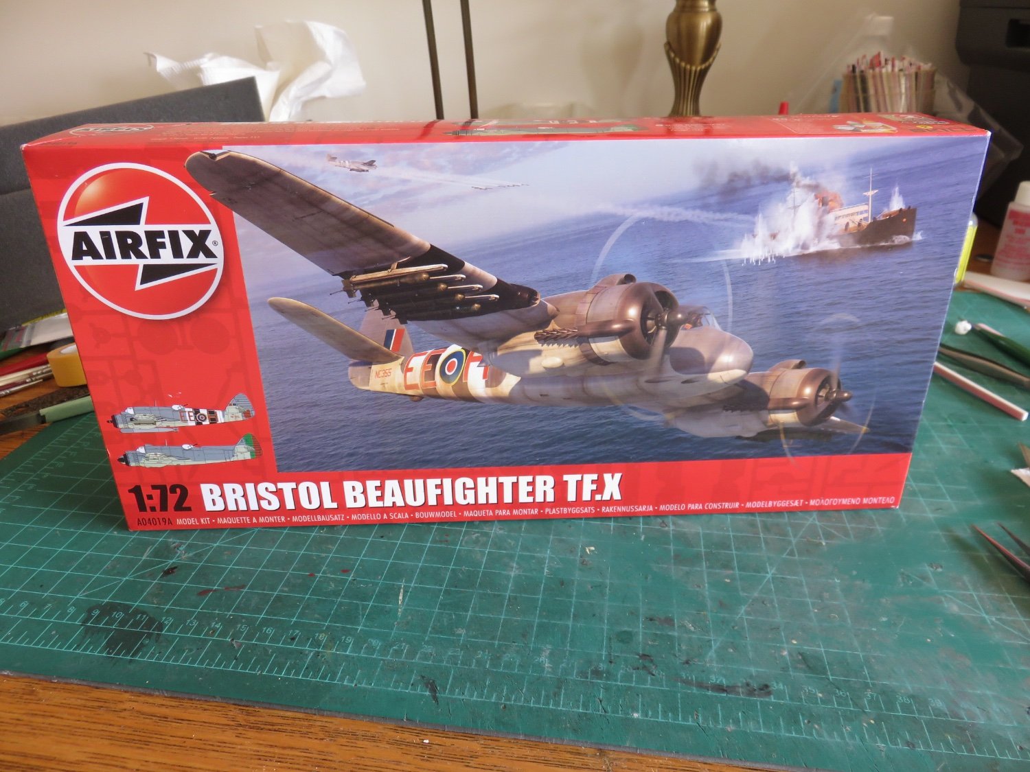
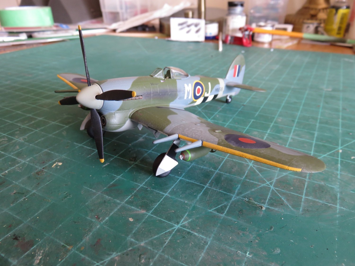
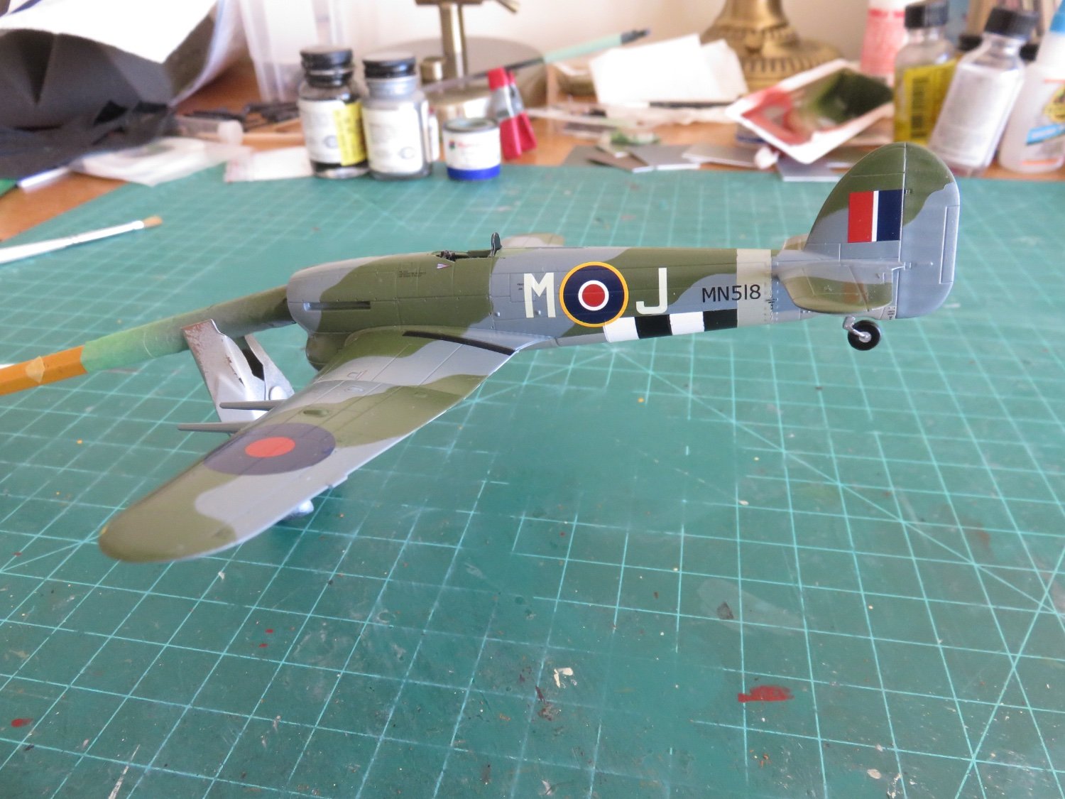
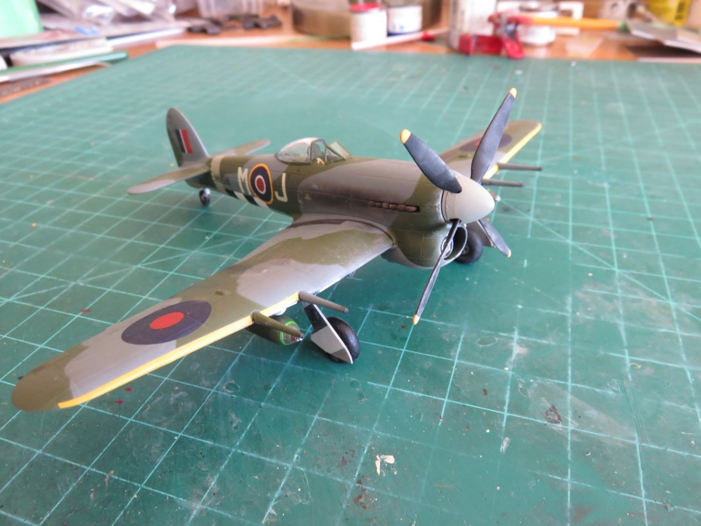
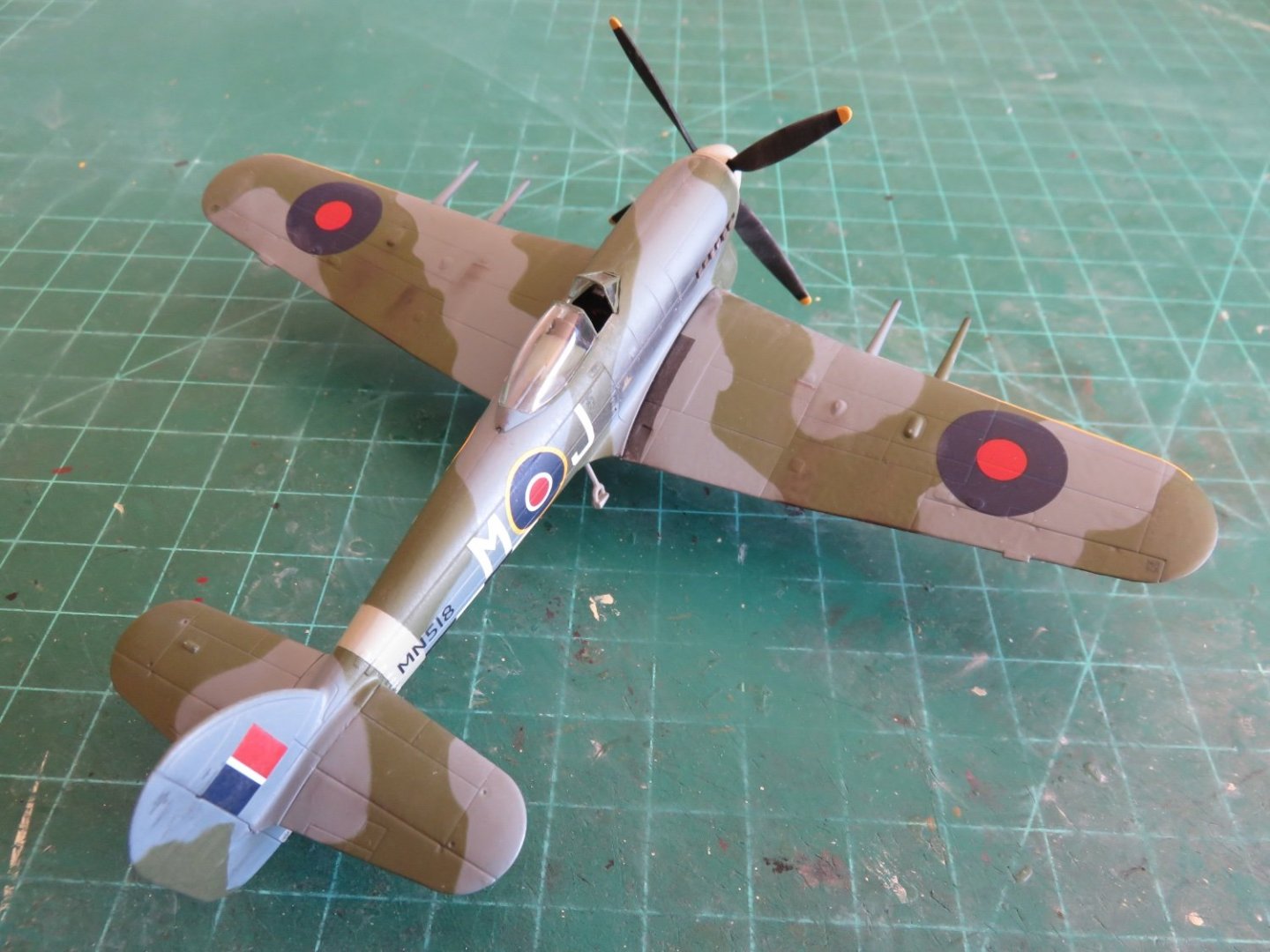
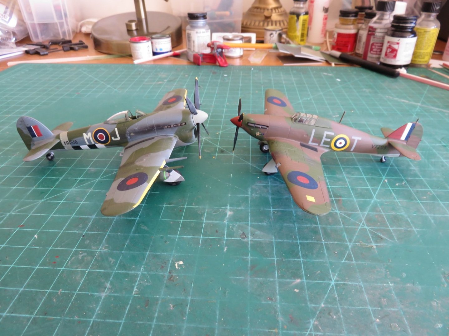
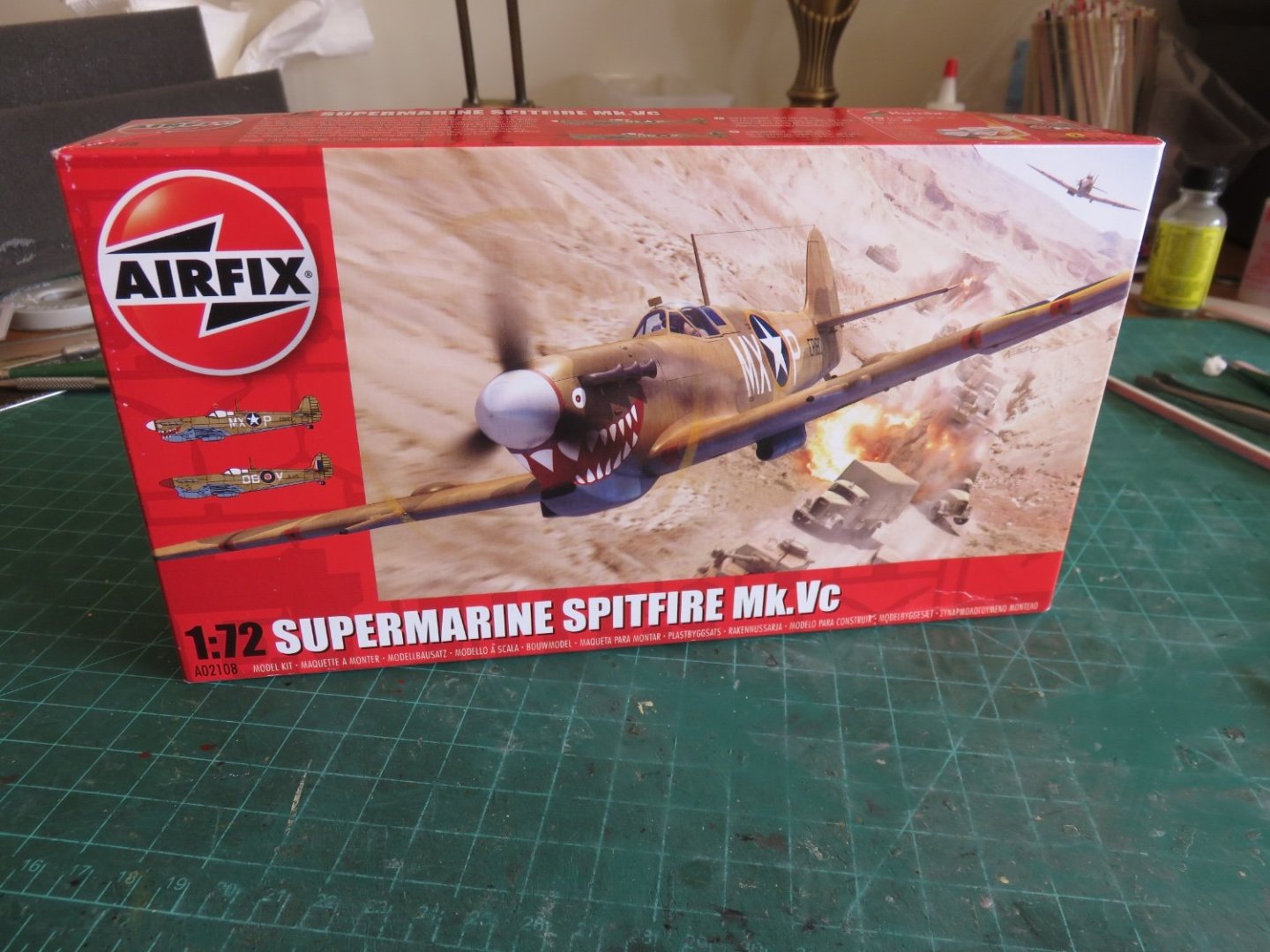
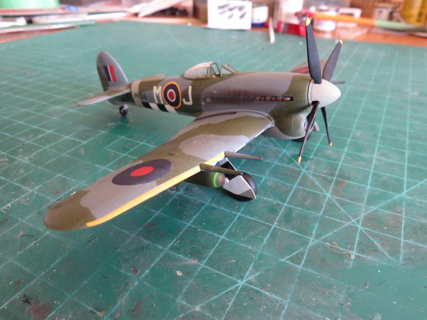
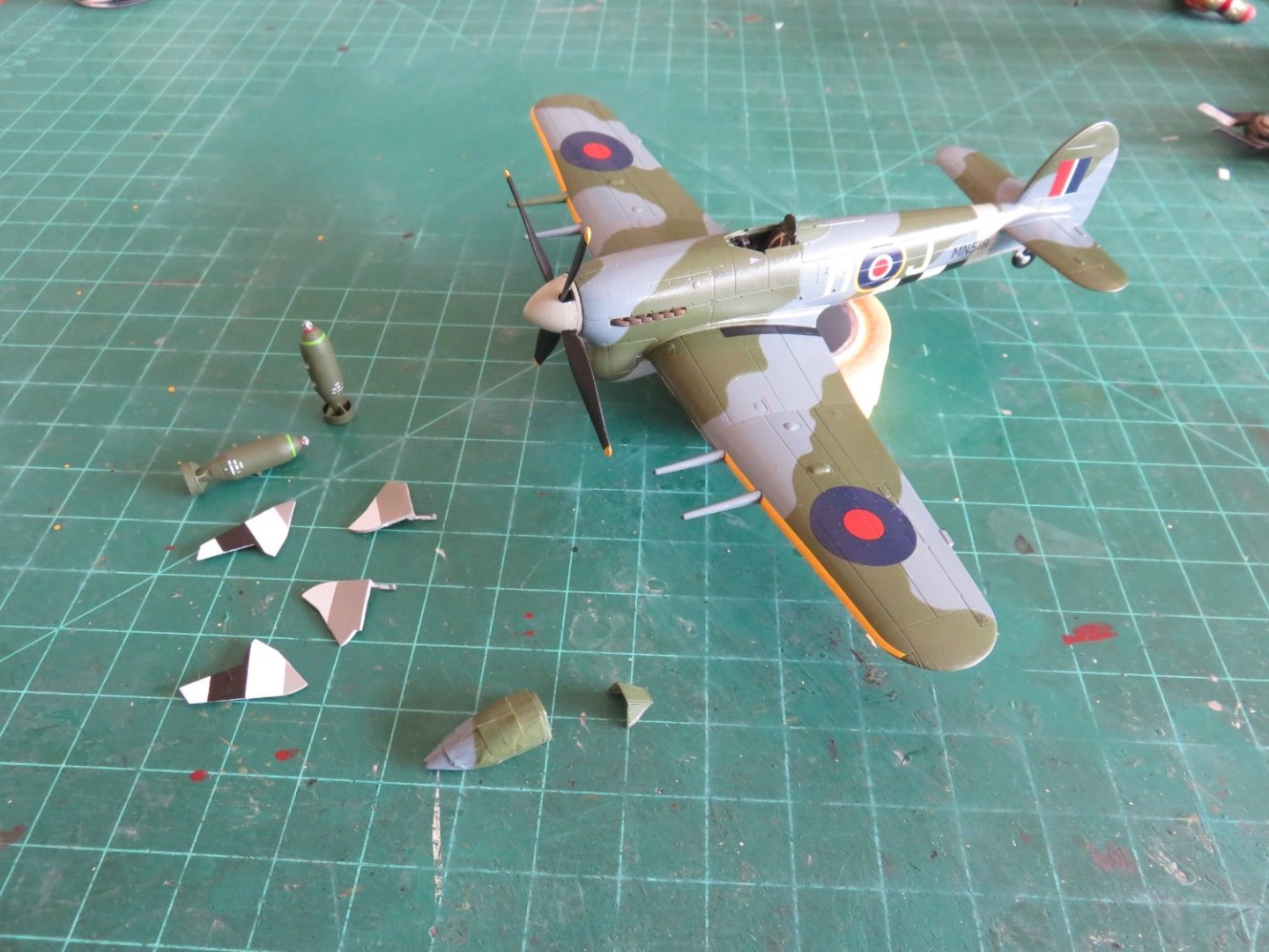
Thanks everyone for following me on this build, as well as all your kind comments, intriguing insights, and generosity. I think its time to call this one finished. A little bit more weathering has been added to the leading edges of the wings, especially in way of the propellor, where the prop wash would kick up sand and grit. I've also dusted some more grime along the propellor blades. The leading edge fade came out nicely on the underside (I think). Finally, a little head to head with the Typhoon's predecessor. I have a couple more WWII planes that have found their way into my stash. I'm not sure if I will get to them this building season, or whether they will turn up in the fall. The weather is beginning to warm up and there's a ton of outdoor work that has been left to pile up while I've been recovering from my collarbone injury back in January. In no particular order, I managed to get a Spitfire Mk Vc, about which there was some discussion about replicating one of George Beurling's planes from Malta: I've read mixed reviews about this particular kit, mostly surrounding some potential issues with the fit, particularly there is the potential for some considerable gaps at the wing root area. From what I've seen in various assembly videos it's not an insurmountable challenge to overcome with a little modelling skill and ingenuity. I've also picked up a Beaufighter TF X: This one comes out-of-the-box with RCAF 404 Squadron markings. Since I didn't get to do a rocket firing Typhoon, this will be a good substitute. Again, in which order I attack these builds is up for consideration. I need to look at aftermarket decals for the Spitfire, as the kit supplied lettering doesn't contain any of the letters I would need for any of Beurling's more well known planes (BR323 "S", BR301 "UF S", EP706 "T L"), I know Xtradecal does make a "Spitfire MkV" set which does include lettering for BR323, I may piece this one out of some of their generic lettering sets to keep options open. For the Beaufighter, I've already purchased a replacement instrument panel (that came along with the panel for the Tiffie), but otherwise there's not much to do with that kit other than build and paint. All in all, I've enjoyed building these little 1/72 Airfix kits. While they don't necessarily have the most detail, or a large part count, they don't take an inordinate amount of time to build and paint, but they do allow the builder to reach that "done" stage in a satisfying amount of time (which really only serves to further the model building addiction, but in a good way). Once again, thanks to all who have been following along, offering such kind compliments, and contributing with your knowledge and ideas. Andy

- 146 replies
-
- 11
-

-

-
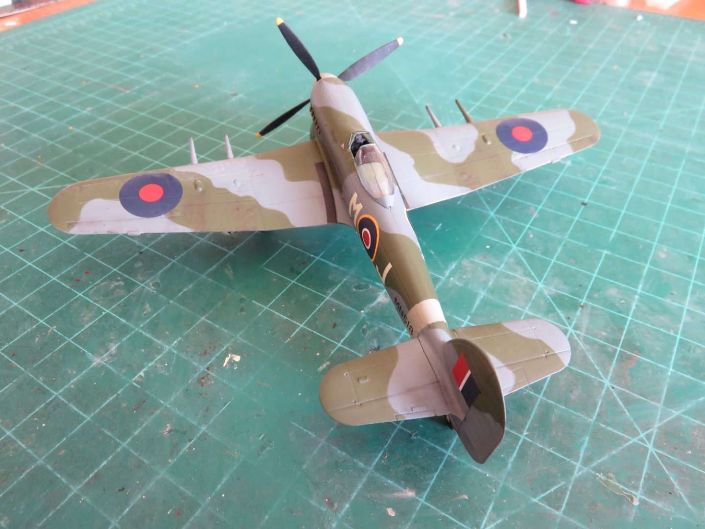
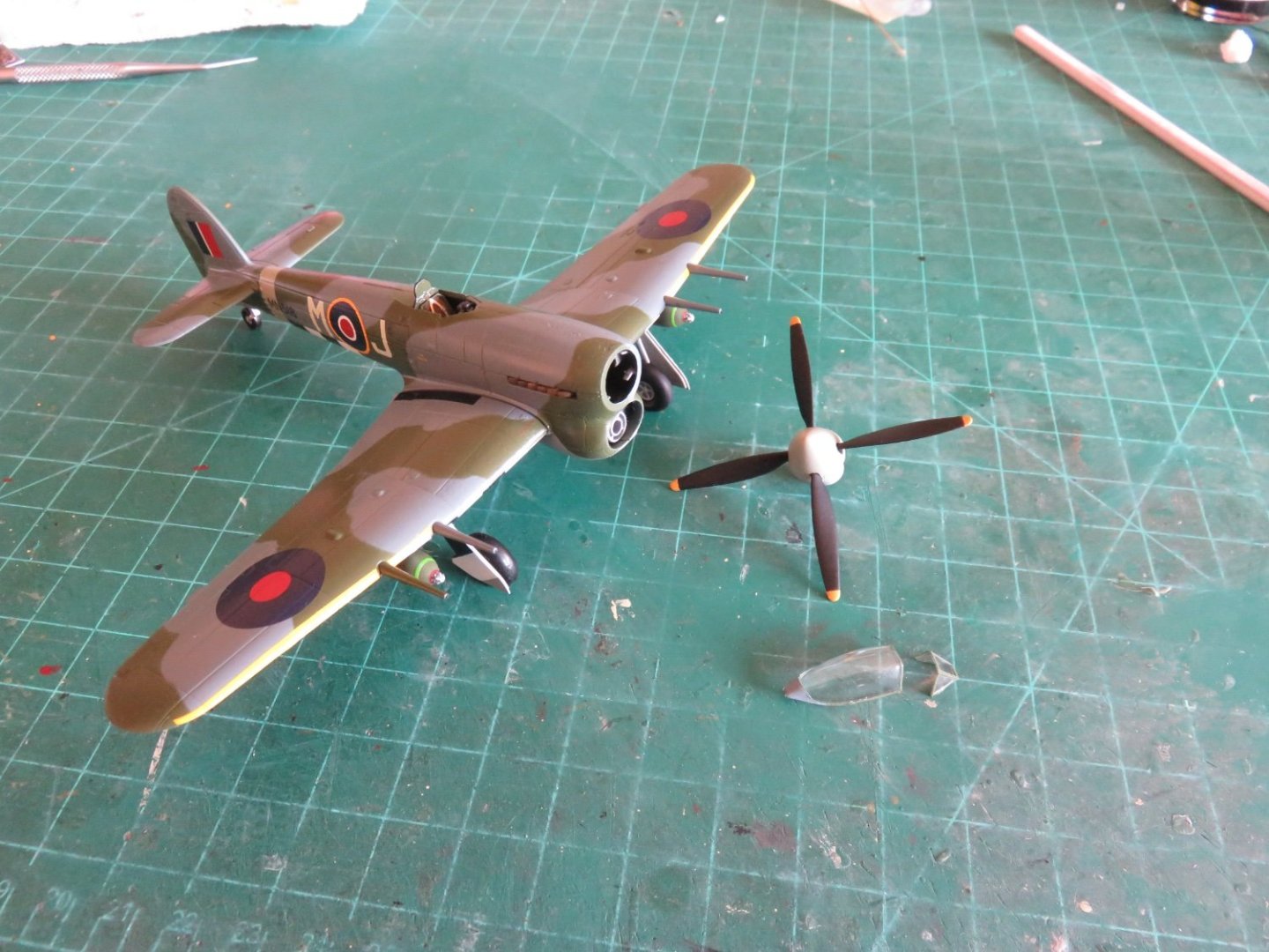
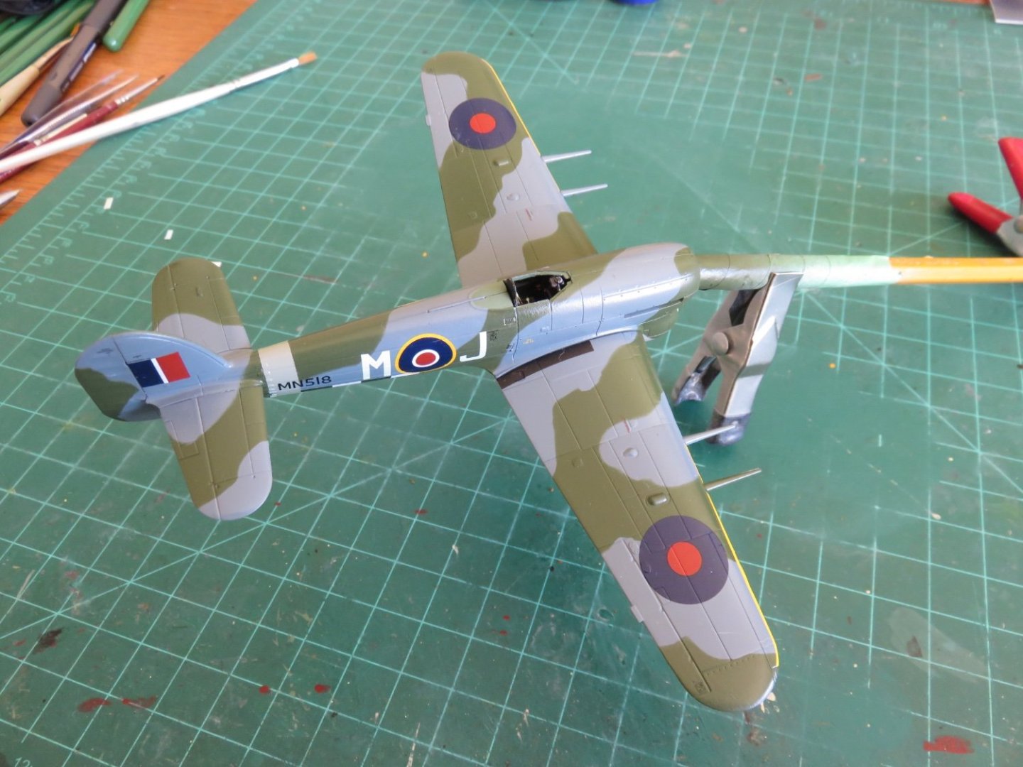
Getting near the end. Final assembly consisted of adding the canopy and propellor. The fit for the latter is quite snug and shouldn't require glueing. All the better to ensure the propellor spins freely. The canopy was posed in the open position, but prior to glueing I dry brushed some silver/aluminium along the top edges of the cockpit, to represent chipped/worn paint in the area where the canopy (and clothing, and hands) would rub. It's hard to see at this scale, but at the right angle, there's a satisfying glint of shiny "metal". I've also lightly dry brushed some silver on the leading edge of the prop, I may have to add a touch more. I have since begun weathering using a variety of pastels from Pan Pastel. They're easy enough to use, and if you have a clean applicator, you can "erase" any mistakes. So far I've added soot and other streaks around various likely areas such as the exhaust and radiator outlets, as well as around the gun bays and ejector ports (although one port is hidden in a black stripe). I have a little bit left to do, I'm planning to add a decent bit of "fade" on the wings' leading edges to simulate the effects of dust and grit (and greasy hands and boots). My goal is to make this plane look like it's been working hard, but not too crazy grimy, (like the plane in the photo I posted yesterday). This is, after all, the Wing Commander's personal plane. One does have to keep up some kind of an appearance. Andy

- 146 replies
-
- 13
-
-
Yep, I’d nope right the heck out of that Kubelwagen with maximum quickness….
-
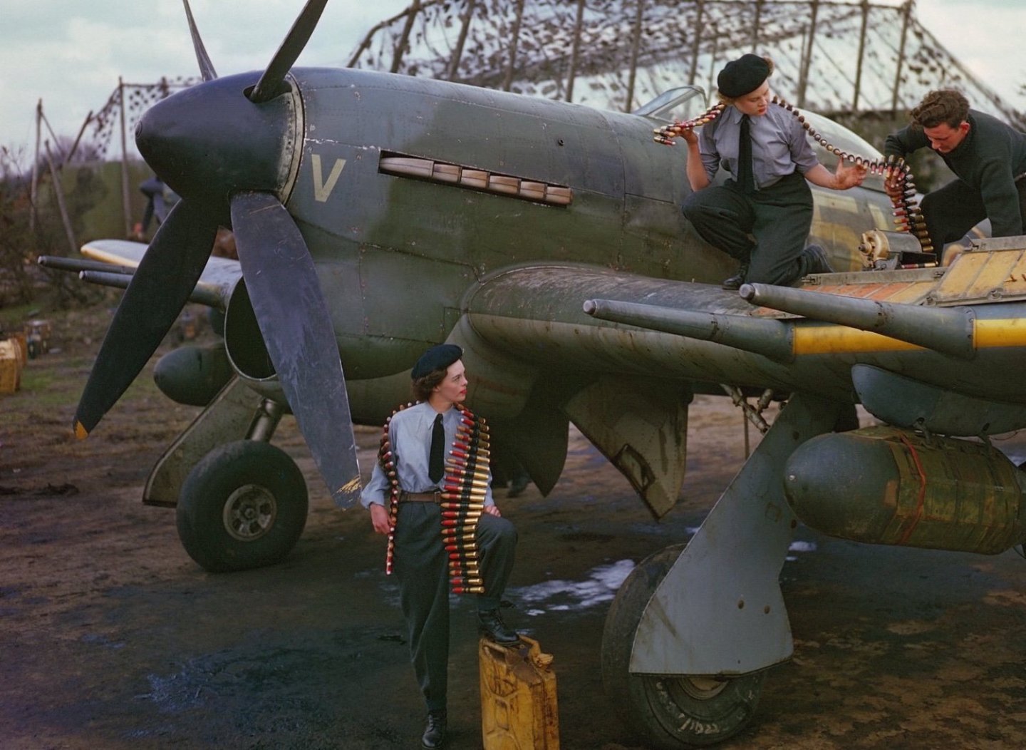
This propaganda photo was taken in Holland later in the war. Things didn’t get any better: Looks like the seals on the landing gear door hydraulics are leaking. I’d swear that is rust on the wing lower leading edge, but it could just be the mud on the upper surface dripping down. There appears to be brake shoe residue on the inside of the starboard wheel bay door, and the lettering on the fuselage side looks yellowed, and thoroughly grime covered. Paint chipping and wearing off all over… Andy
-
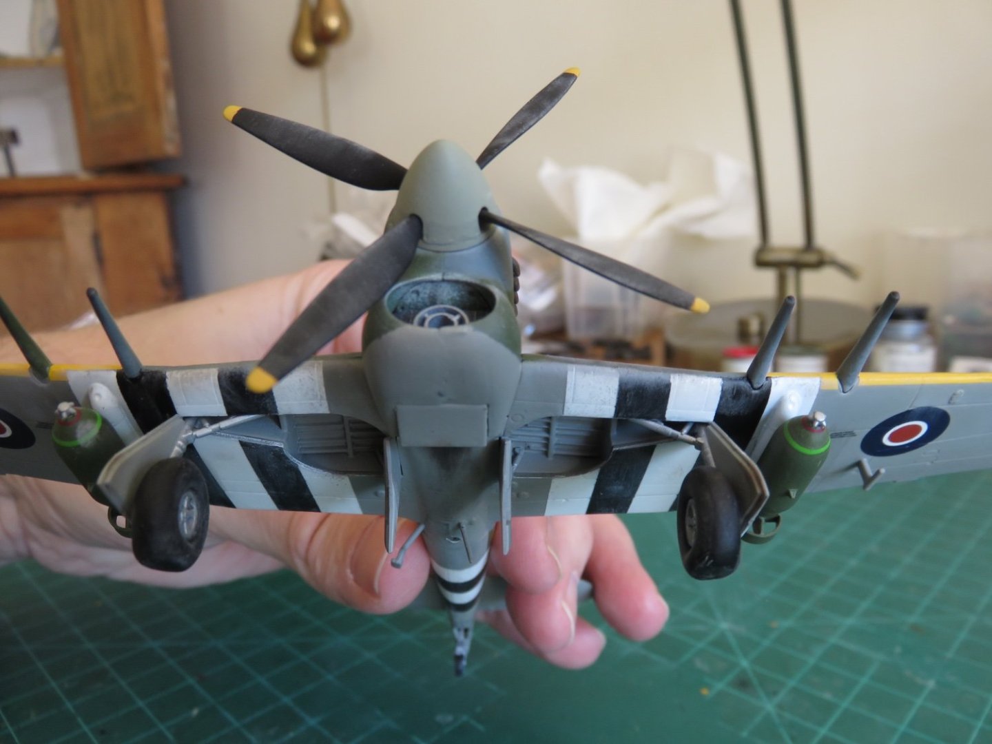
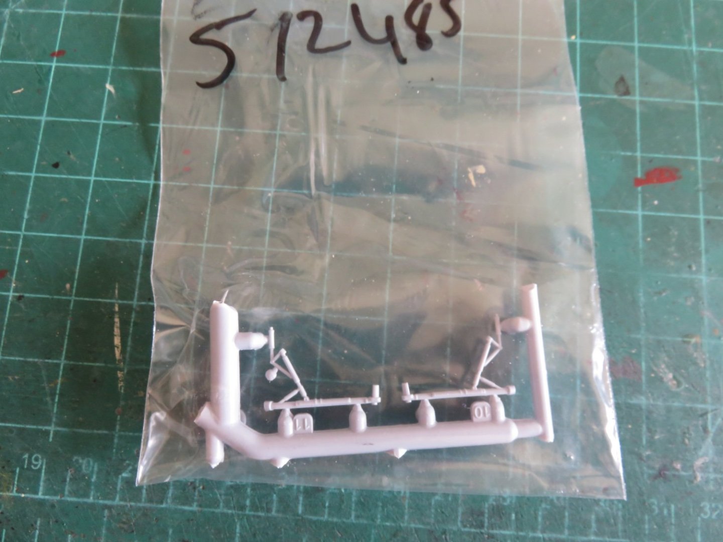
As promised, a more thorough update. The replacement landing gear legs arrived unbroken and properly moulded (no short shots), and very well packaged (Thanks Airfix!). I quickly had them cleaned up and painted. Following which all of the underbody components could be added The landing gear is a little spindlier than on other models as there are no bracing struts, and, coupled with those massive wheels and tires, care must be taken not to inadvertently snap anything. I would have liked if the landing gear doors actually glued to the underside of the wing (it would have added a modicum of support), but by design there's a tiny sliver of a gap, so unfortunately not. All that remains to be done is to add a sealer coat of Dullcote and add the propellor and canopy (open, this time, to see the cockpit). The end is drawing near on this build, but I am planning to add a decent amount of weathering. Even though this is the Wing Commander's airplane, I'm sure in the hot and hectic summer of 1944, cleanliness took somewhat of a backseat to the operational requirements of the moment. Some photo's I've seen of regular squadron assigned airplanes look like they've been royally run through the wringer. Andy
- 146 replies
-
- 11
-
-
Wow, thanks guys! I’m really flattered you all feel that way. I haven’t wasted any time, so I’ll have a full update tomorrow, I hope. @AJohnson Dusting is always good! You can pass it off as doing housework! 😆 Andy
-
Thanks, everyone, for all your patience! I received a small package in the mail today, and I’m pleased to report that my replacement parts have arrived safely!! I can now resume my build and see it to completion! Overall I am pleased with Airfix’s response. I would suggest that anyone else with kit issues shouldn’t hesitate to contact them, just be patient. On with the build!! 😁 Andy
- 146 replies
-
- 10
-
-
English fleets and small vessels in the early 1700s
realworkingsailor replied to Dan DSilva's topic in Nautical/Naval History
If you can find a copy, “Sloop of War, 1650-1763” by Ian McLaughlan is a great resource. Andy -
If you’re looking for random opinions, (and mine can get very random if needed 🤪), I’d say leave it open, bombs or not. You could display them beside the model on a bomb trolley or something, if you felt. For my Wellington, I’m very happy I left the bomb bay open and would have done so even if I didn’t get the aftermarket PE. Appropriate or not, showing off some of the “guts” can make for a nice interesting model. Andy
-
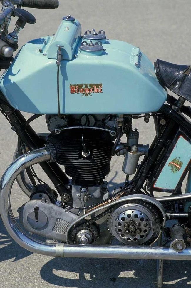
As an alternative to rubber, have you considered using something else? Have a look through Michael Mott’s pilot cutter build. He made some nice scale seating using pigskin: Even some kind of appropriate coloured simulated leather might work, stretched over a wooden mould of your motorcycle seat. Andy
-
And if she finds out, tell her it could be worse: https://brasstrains.com/Classic/Product/Detail/148492/G-Scale-1-32-Brass-Model-FAM-Fine-Art-Models-PRR-Pennsylvania-Bucyrus-Erie-250-Ton-Crane-490903-1996-Run 🤭😁 Andy
-
This ain’t Alcoholics Anonymous, we’re all enablers of this shared addiction… no point trying to fight it… sit back, relax and enjoy the online shopping! 🤪😁 Andy
-
I know where a few of them are hiding: https://www.sunwardhobbies.ca/wingnut-wings-32053/ https://www.sunwardhobbies.ca/wingnut-wings-32045 (Three of the first and one of the second) And a couple more here: https://wheelswingshobbies.com/aircraft/wingnut-wings/ Pricey though…. Andy
-
I did a little further reading, apparently there was also an aerodynamic advantage in that the upper surfaces of both wings were uninterrupted. This allowed a slightly reduced wingspan, without a comparative resulting loss of lift. Andy
-
I think Shipman is right, according to this website, it was an oil tank. Found a prototype photo too: Andy
-
Is there any way you could make it moveable? Or does the assembly preclude that possibility? Andy
-
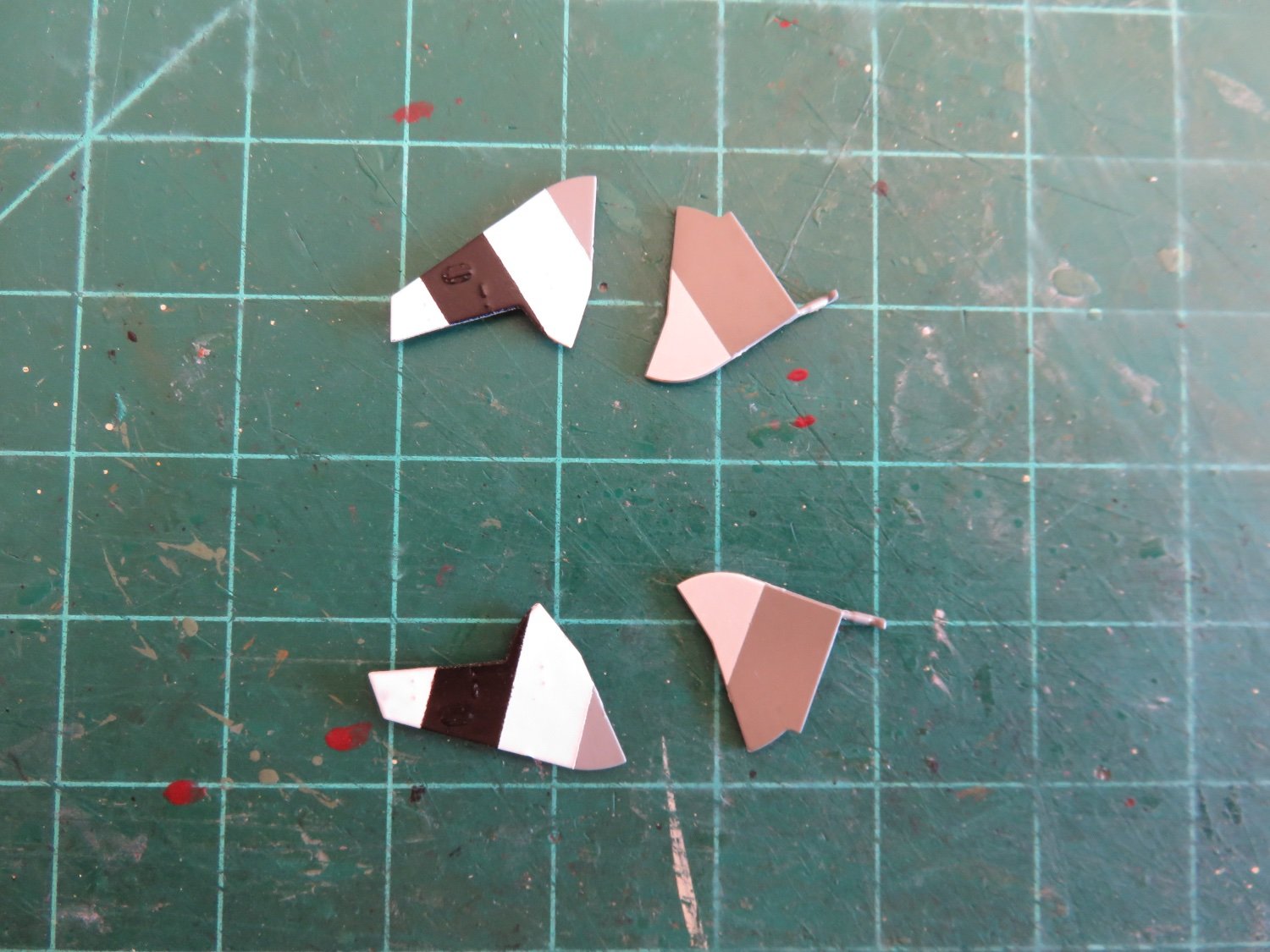
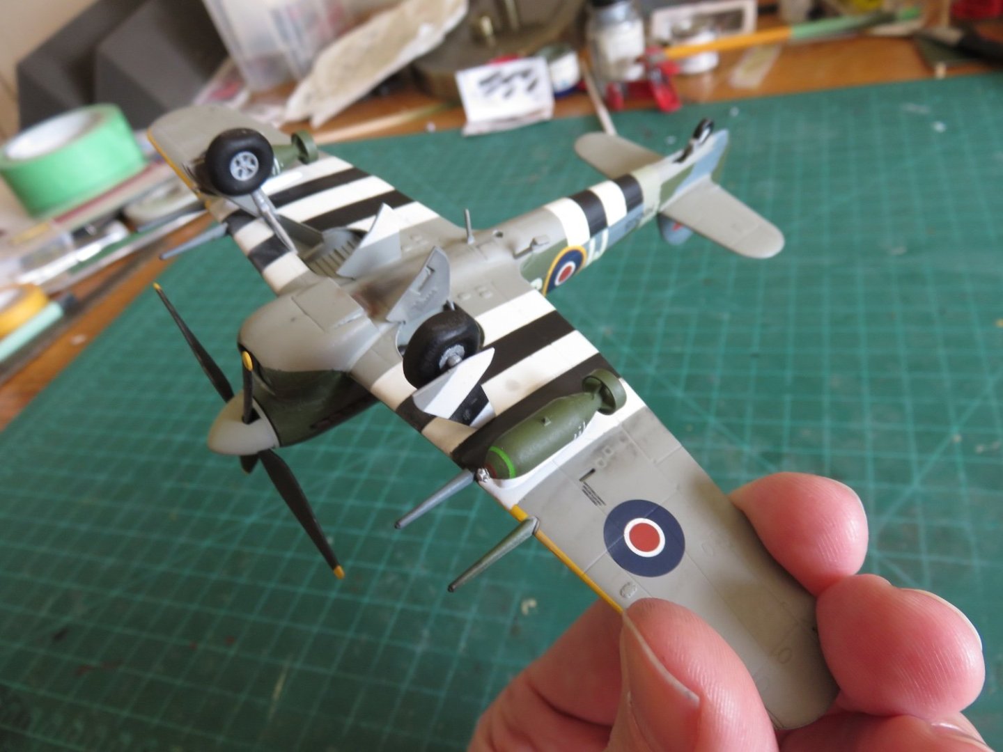
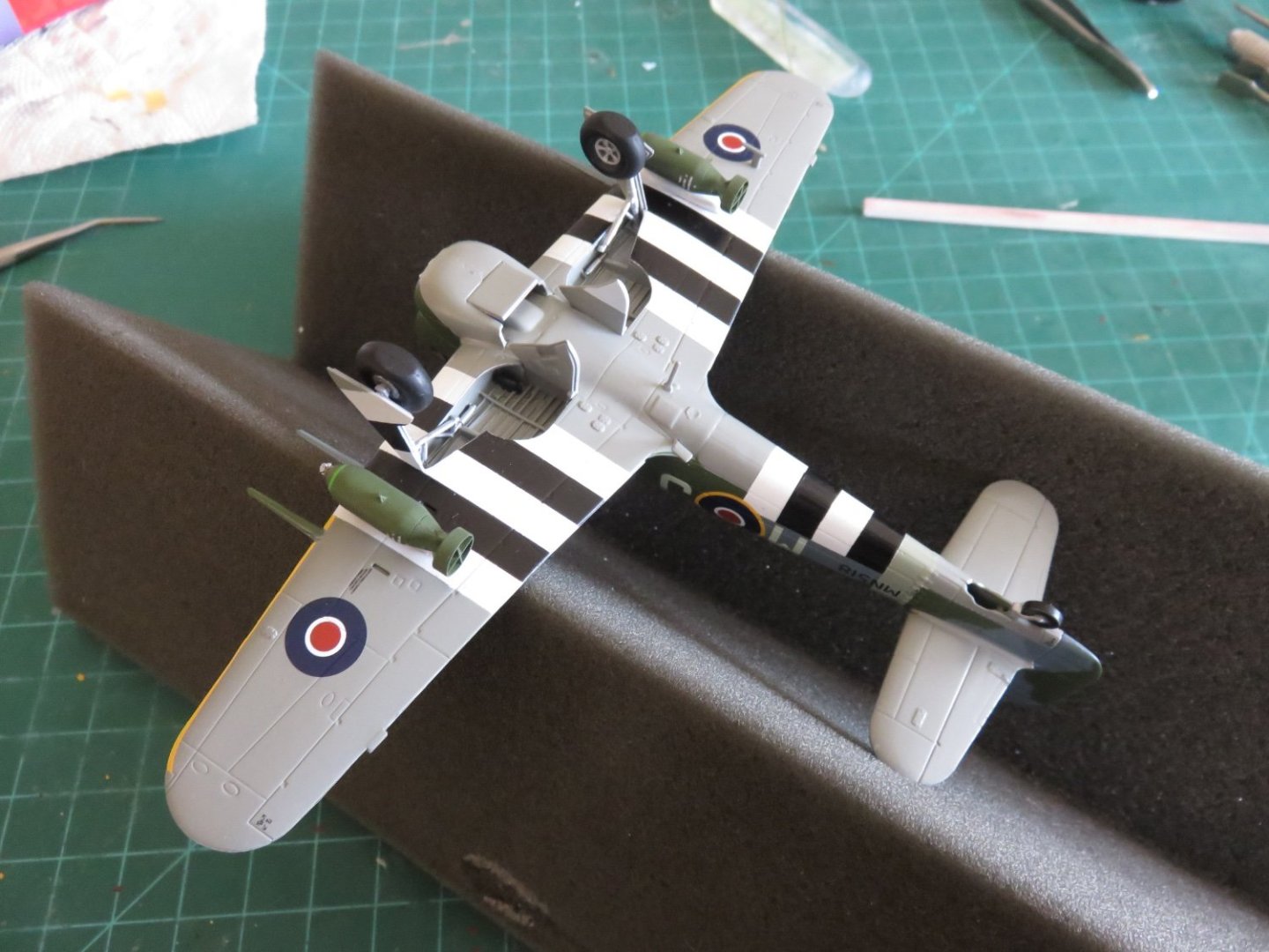
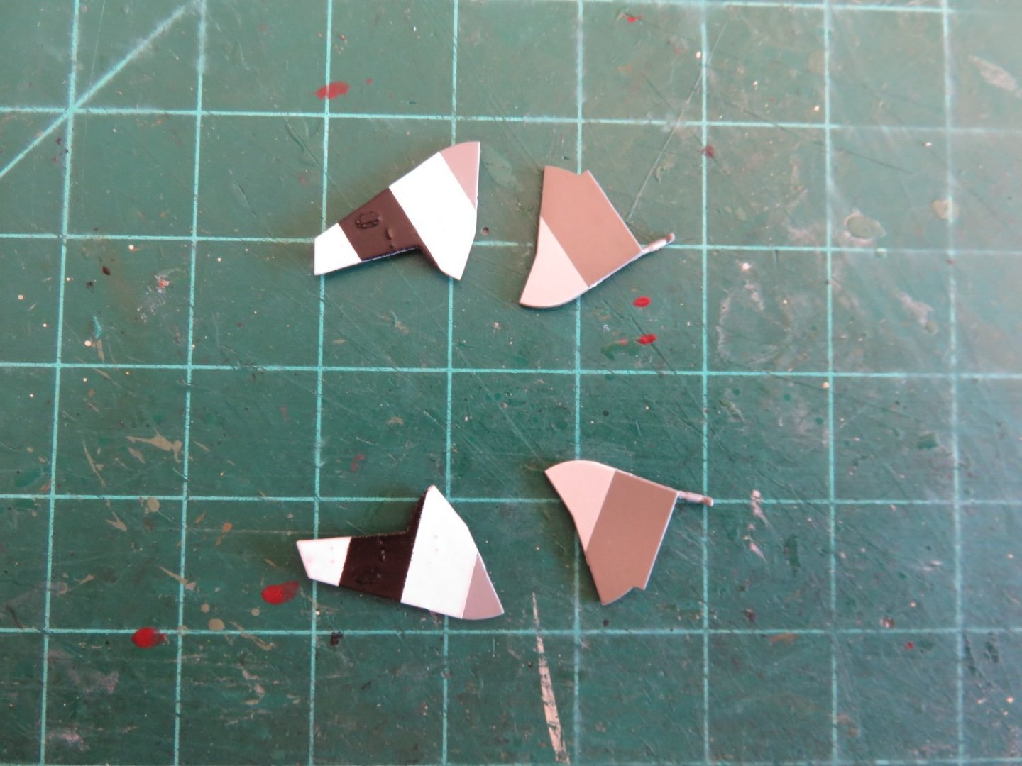
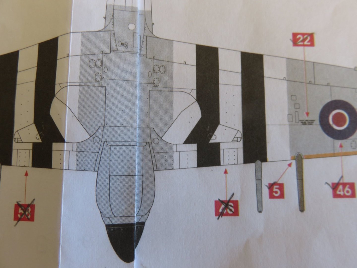
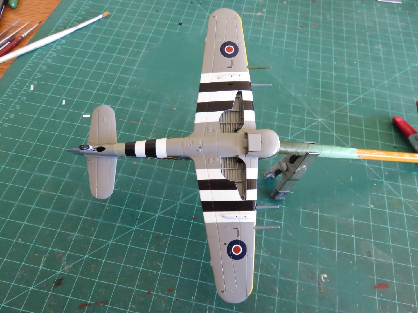
Thanks for all the likes and kind comments! One small update for today, I have finished painting the landing gear doors. Once again, I strayed away from using the supplied decals on the main doors and painted them on as I did for the fuselage stripes. Apparently the ground crew of the kit supplied scheme made a small error when they applied the invasion stripes (see if you can guess what it is 🤔): I've also installed the engine exhaust pipes. They were painted with Humbrol gunmetal followed by a wash of Floquil rust to give a nice burnt metal look. This gets me just about as far as I can go. My usual next step is to paint and attach the landing gear, followed by the last little parts like the arial, pitot tube, etc (any items that would be at risk of damage should an accidental belly landing occur). Until my replacement parts arrive (which I'm really not expecting until the end of this week at the very earliest), I will have to be content to sit and wait. Oh Well.... Andy
-
Well received, thank you so much! Andy
-
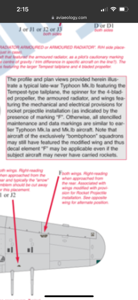
I’ve been doing as much digging on my own as I can, the only real reference that I can find is from a decal company called aviaeology. In their aircraft stencil set for the Typhoon, they are ambivalent on the status of that particular stencil. From what they say, definitely present in rocket Typhoons, maybe/maybe not for bombphoons… In all honesty it’s enough ambiguity for me to leave things as they are, but my curiosity is still piqued… Andy

-
Yes and no. Designed at the outset as a pure fighter (the prototype Typhoon was equipped with 12 .303 brownings), there were performance issues that ultimately made it lacklustre in that role. In the fighter-bomber role, while the Typhoon could carry either bombs or rockets (and were initially designed to be interchangeable), the skills needed to effectively deliver each type of munition were different. The British found it was more efficient and effective for each squadron or wing to specialize in one or the other. All of 143 wing (RCAF) airplanes were bomb carriers from the outset of their transfer to Britain. So I think my question still stands, would that stencil have still been applied to an airplane that, while capable, would not, foreseeably, have been equipped with rockets? I doubt the factories would have applied anything. I think any fitting out would have been done at the various maintenance units, in preparation for whatever frontline unit the aircraft was destined for. Andy
-
Thanks again everyone! The lettering is tentatively finished. As I did with my Hurricane, I laser printed the registration number on blank decal paper. As long as I keep choosing to model airplanes with black painted numbers, I can do this as many times as I like. The font is about as close as I could get and the "1" in 518 is actually a lower case "L", but overall I'm happy. The only spot where I have questions is the stencil located inboard of the underside roundels. It reads "Check Firing Contacts Before Connecting Leads". After I had applied them and figured out what they said, it got me wondering if these stencils are specific to rocket firing Typhoons or were they applied to all Typhoons, regardless. If anyone has information, please let me know. I haven't sealed the decals yet, so removal is still easy. Andy

- 146 replies
-
- 11
-
-
Possibly painted while in the dock. Surprisingly, with the right amount of labour a large ship can be fully sandblasted and painted in a remarkably short period of time (about a week). If the ship was in any way waterborne at the time, it shouldn’t have toppled like that, unless something serious was done to alter the CG of the ship. Most, if not all, commercial dry docks don’t use the old methods where there’s only a single row of blocks under the keel and shoring beams to hold the ship up. Although there are still more blocks down the centreline, there are typically one or more rows of blocks on each side, depending on how wide the ship is. Submarines are, of course, the exception as they usually don’t have flat bottoms…. 😁 Andy