realworkingsailor
-
Posts
3,274 -
Joined
-
Last visited
Content Type
Profiles
Forums
Gallery
Events
Everything posted by realworkingsailor
-
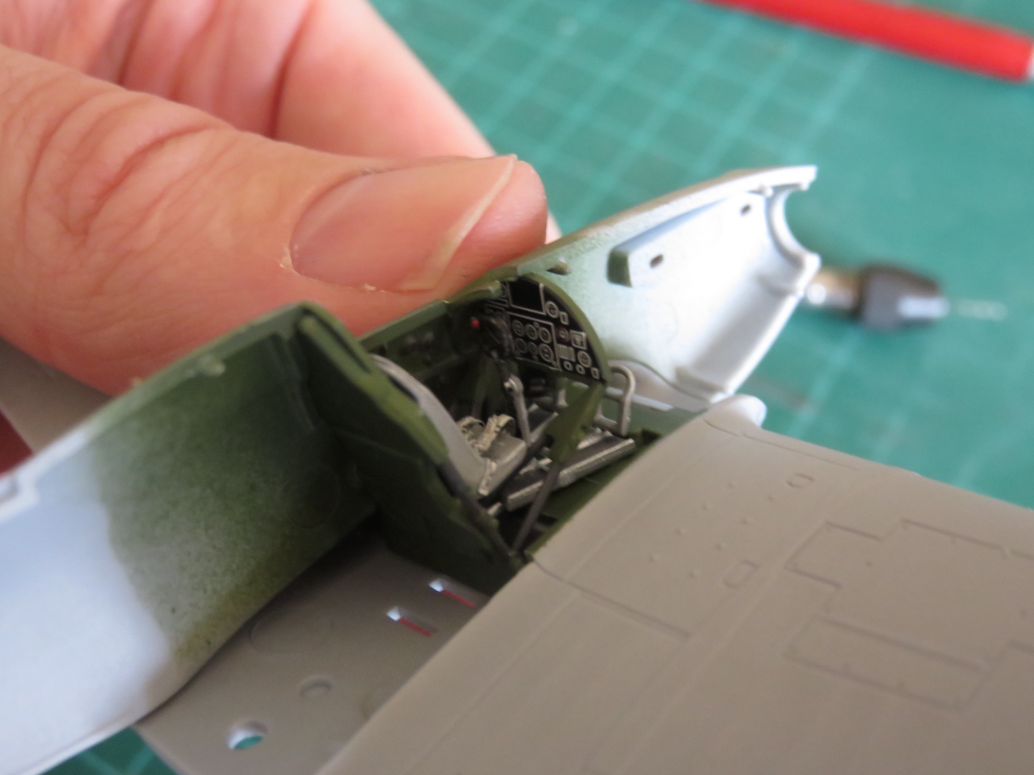
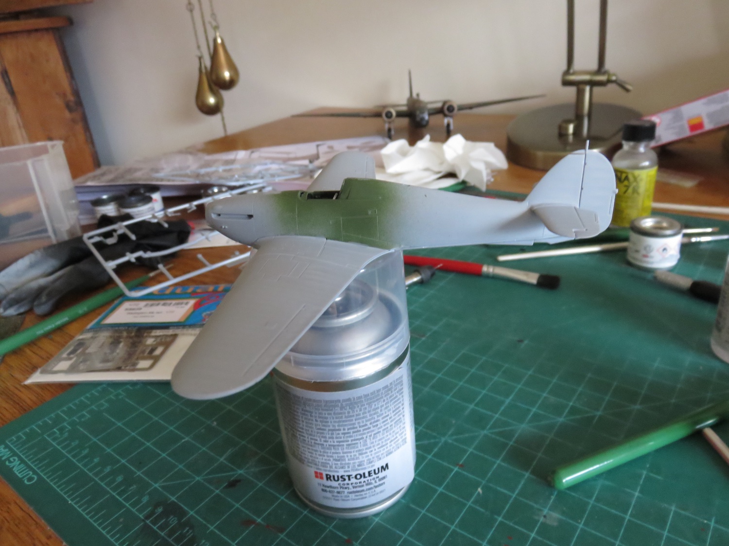
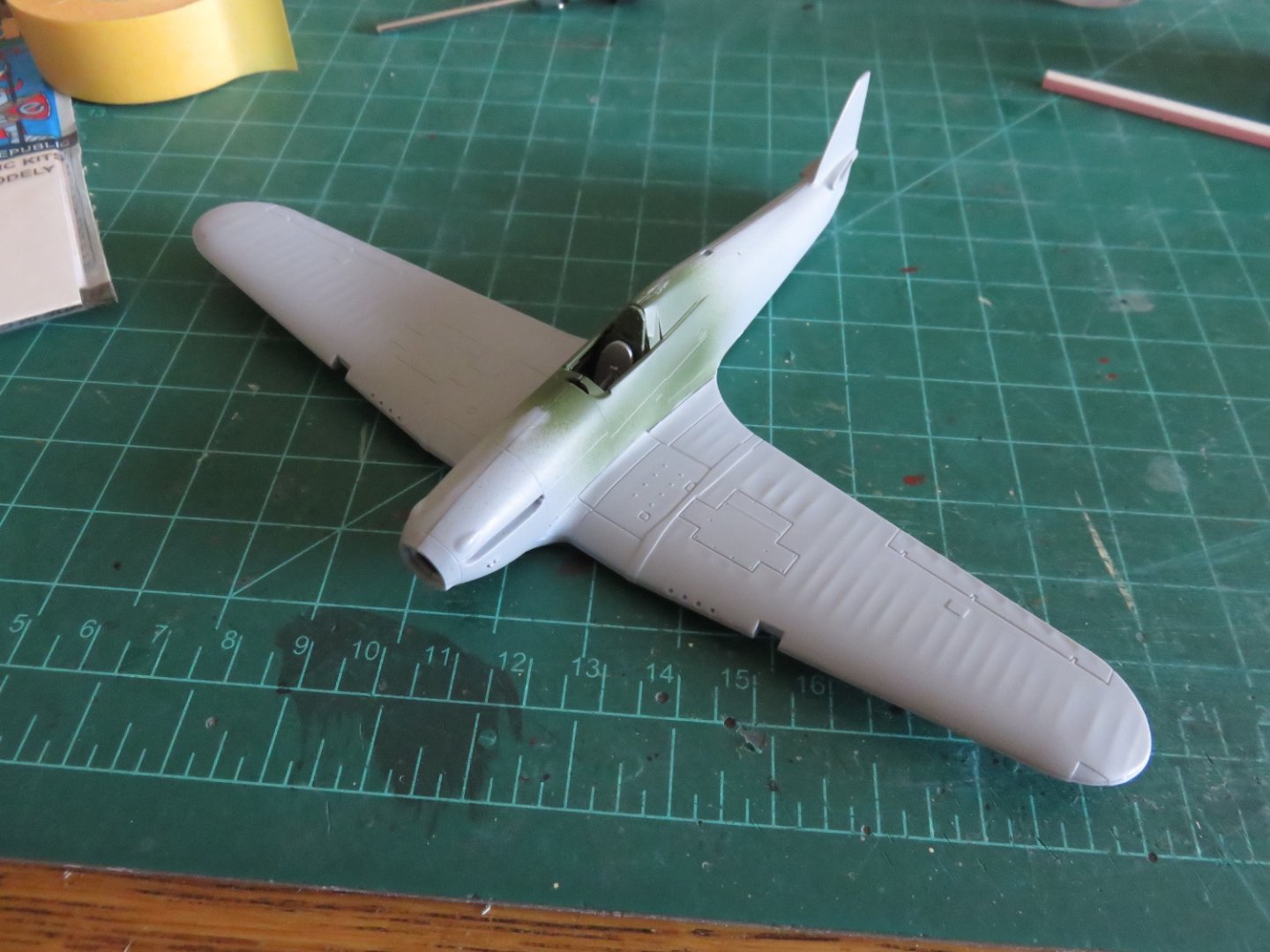
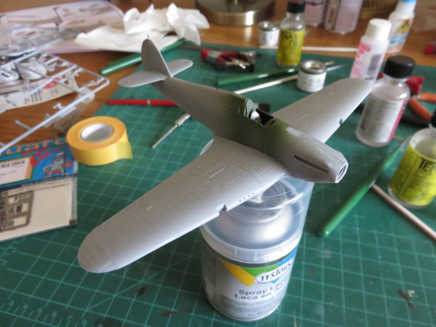
 If nothing else, this build moves along pretty quickly. I left off yesterday about to finish the cockpit. Well, that didn't take too much of my time. All done. Very simple after all the complex fiddling about that I did building the Wellington. The seatbelts fit not too badly, and add a little touch of extra detail. The instrument panel was a basic decal. The heavy white lines actually make it slightly more visible (in a much smaller space) than the layered PE of my Wellington. A quick dry fit to make sure all the components will slide together nicely. I only had to tuck the ends of the seatbelt a little further under the seat to avoid them getting pushed up above the seat pan. For the most part I painted the interior green with aluminium components and gun-metal highlights on the details and various struts and whatnot. After the cockpit, things move swiftly and before long there was something that looked like an airplane. For the most part the fit was okay, but there are a few small seams that will need addressing with some filler. The after part of the wing/fuselage transition has the most obvious gap, but there are some small ones along the horizontal stabilizers and one the left side of the tail fin. There's also a bit of a lip on the chin of the plane, where the wing assembly meets the fuselage, that will need some sanding and maybe a little filler to smooth out the transition. I don't expect too much trouble dealing with these little areas. Andy
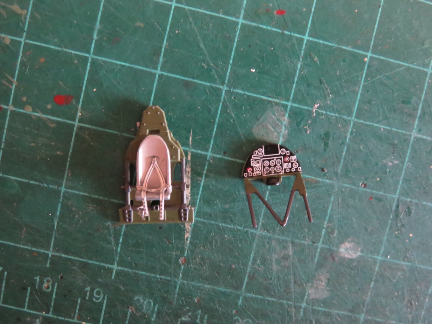


- 92 replies
-
- 15
-

-
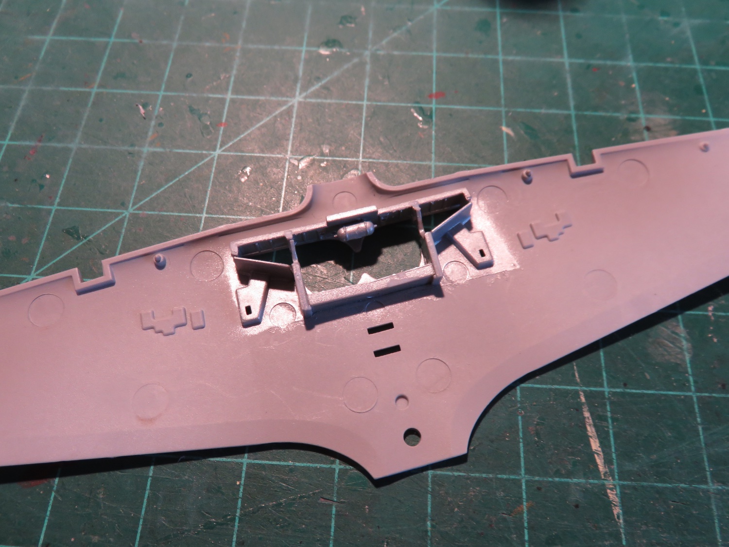
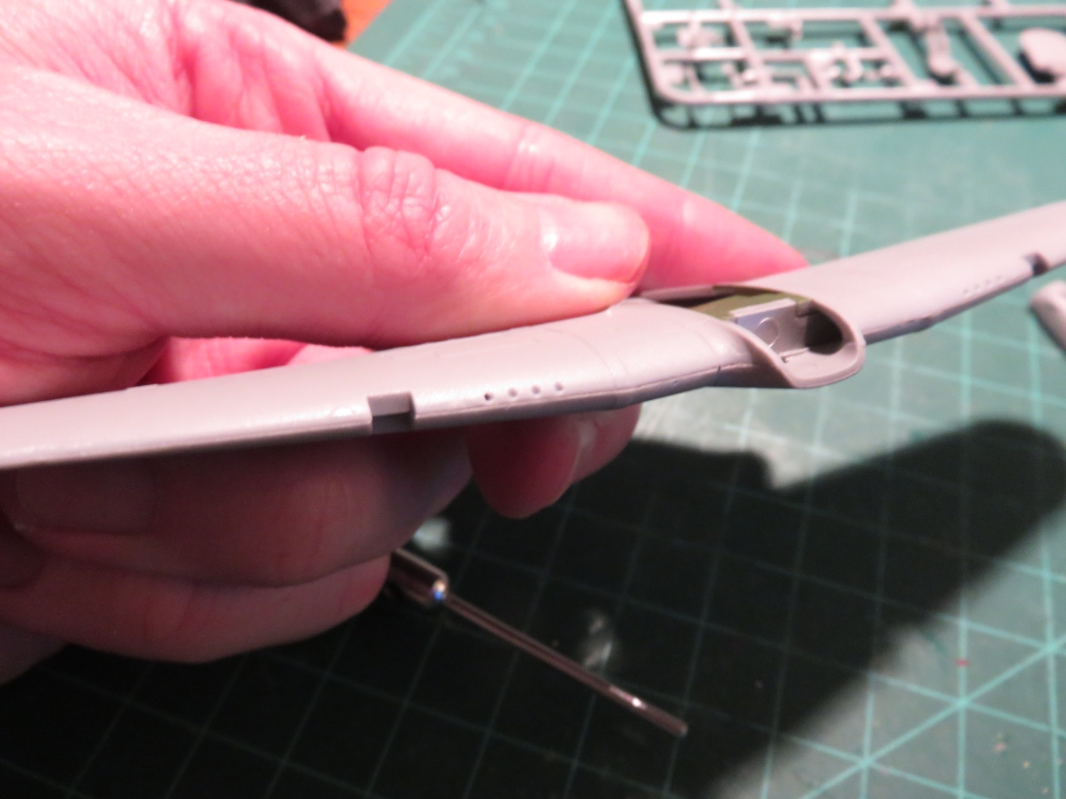
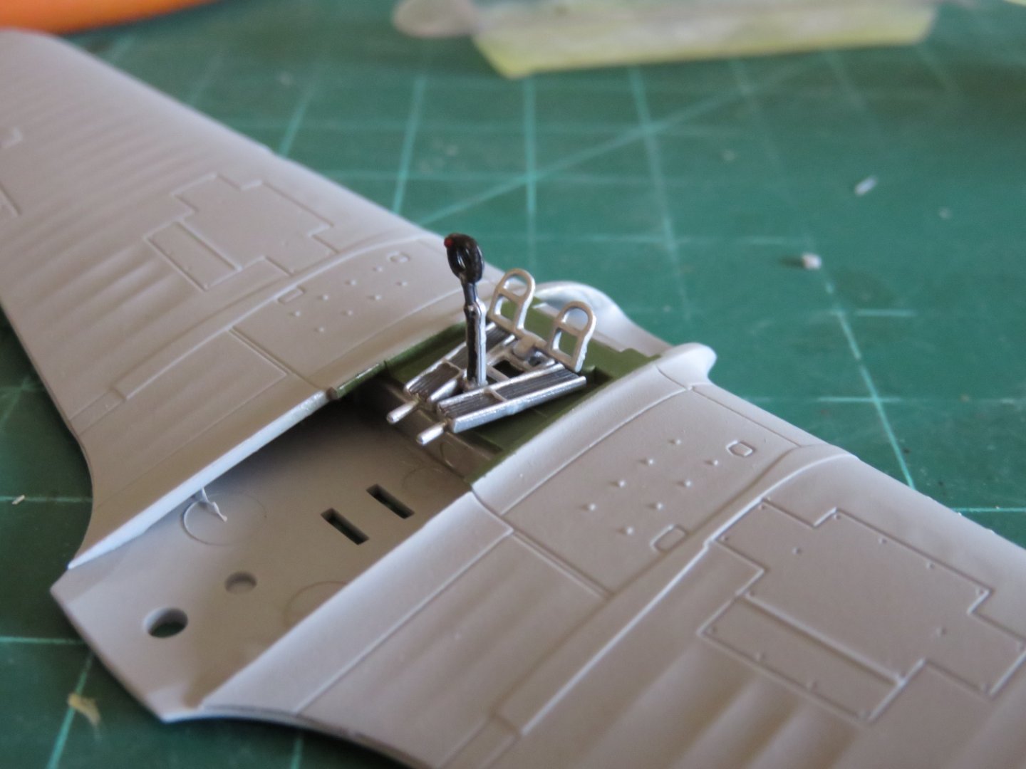
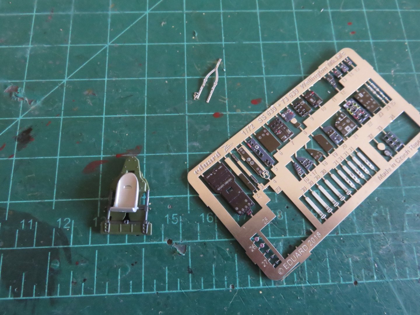
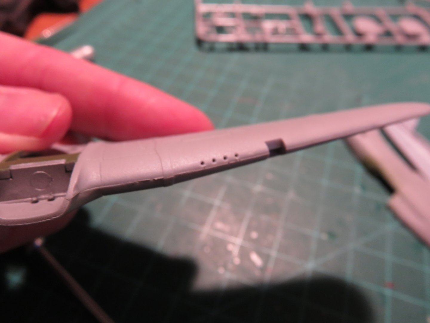
Time to get stuck into it, or, what to do on a gloomy January day (it's been cloudy and wet and just generally bleh weather since the weekend, good hobbying weather!) The build starts simply enough with building the landing gear bay in the lower wing: Nothing too complicated, but reasonably detailed for this scale. I pre-painted the parts in aluminium before assembly. This was quickly followed by adding the upper wing surface: A little bit of a seam remains to be addressed, but otherwise the parts went together rather well. No alignment issues to speak of. After the glue had set, I then drilled out the "gun ports". To me, the little moulded dimples lacked appropriate depth, and look much more realistic having been opened up. Moving along, the next step involves adding the cockpit foot plate, rudder pedals and control column: I will continue to take some liberties with the suggested paint scheme. Mostly to show as much of the details as possible. The cockpit is fairly small and once enclosed some things will likely not be seen anyway, but I thought I should do my best to make it possible that these details are not entirely lost in a monochromatic darkness. Work has not turned to the aft bulkhead and pilot's seat: I've opted for the armoured bulkhead, there's a little more detail on it (for the sake of interest) and I will be adding some PE seatbelts. Fortuitously, I had some PE leftover from my Wellington build, and while these belts might not be 100% correct for a fighter plane, they should do the job. I actually have two entire frets left over, as I had mis-interpreted what was included in each set when I ordered them, and Eduard mis-interpreted the number "1" when packaging this particular set. Happy accidents! I am really enjoying this build so far, it's a nice little kit and well worth it. Andy


- 92 replies
-
- 14
-
-
If I’m not mistaken, many of us are approaching that milestone on this particular iteration of the forum. I believe the ten year anniversary of the “Great Crash” is coming up in February. I was a member here for a couple of years before that historic event. I wonder if @James H will be throwing a party to celebrate? 😁 Andy
- 92 replies
-
- 10
-

-
-
Thanks for comments, guys! I figured if I shook the tree hard enough, a few purists might fall out!🤪 I’ve made my decisions based on my preferences on how I want my build to look, rather than going for 100% historical accuracy. I do appreciate the information, however. Andy
- 92 replies
-
- 11
-
-

-
Every hobby paint manufacturer seems to have a different name for the colour. Beige-grey, green-grey, off-sky… (okay I made that last one up, but it sounds good… like “off-white”). A lot of people forget that while the Spits get all the glory, the Hurricanes were responsible for 60% of enemy aircraft lost during the battle. Andy
- 92 replies
-
- 10
-
-
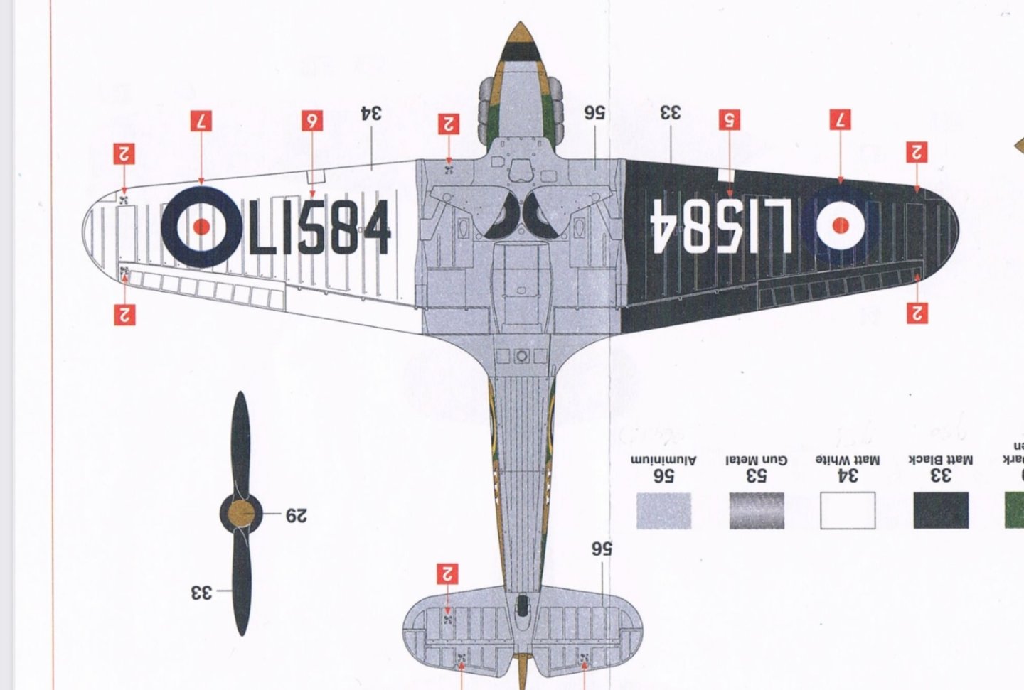
Not saying it doesn’t have its place, just not for me 😁. I’ve done one airplane with the camo-over-black, I want to do something different. Actually, I don’t mind the scheme from the first release of this kit, a pre-war black and white with silver down the middle: But in my kit there are no decals for the large registration numbers under the wings, so it wouldn’t look right…. Andy
-
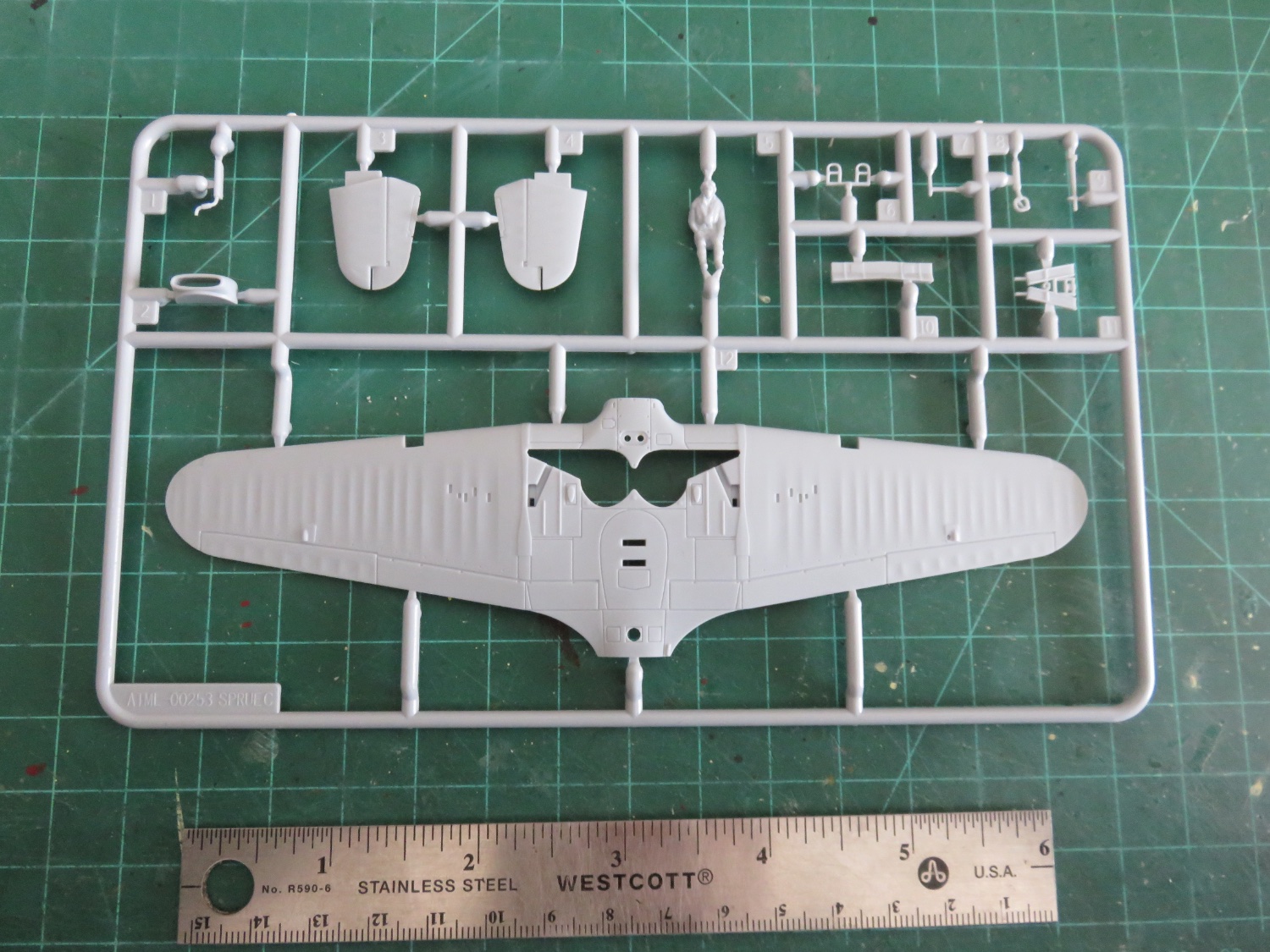
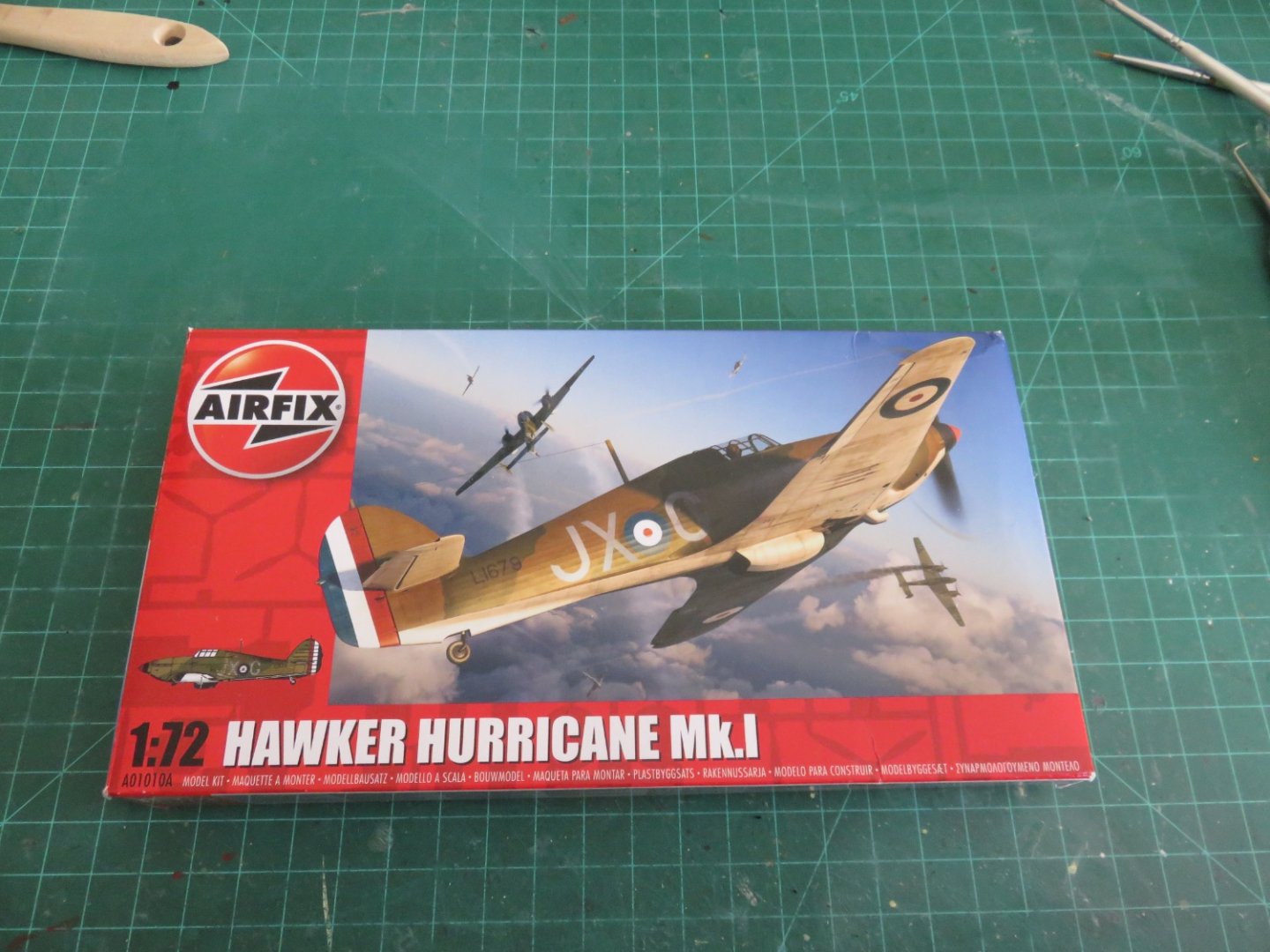
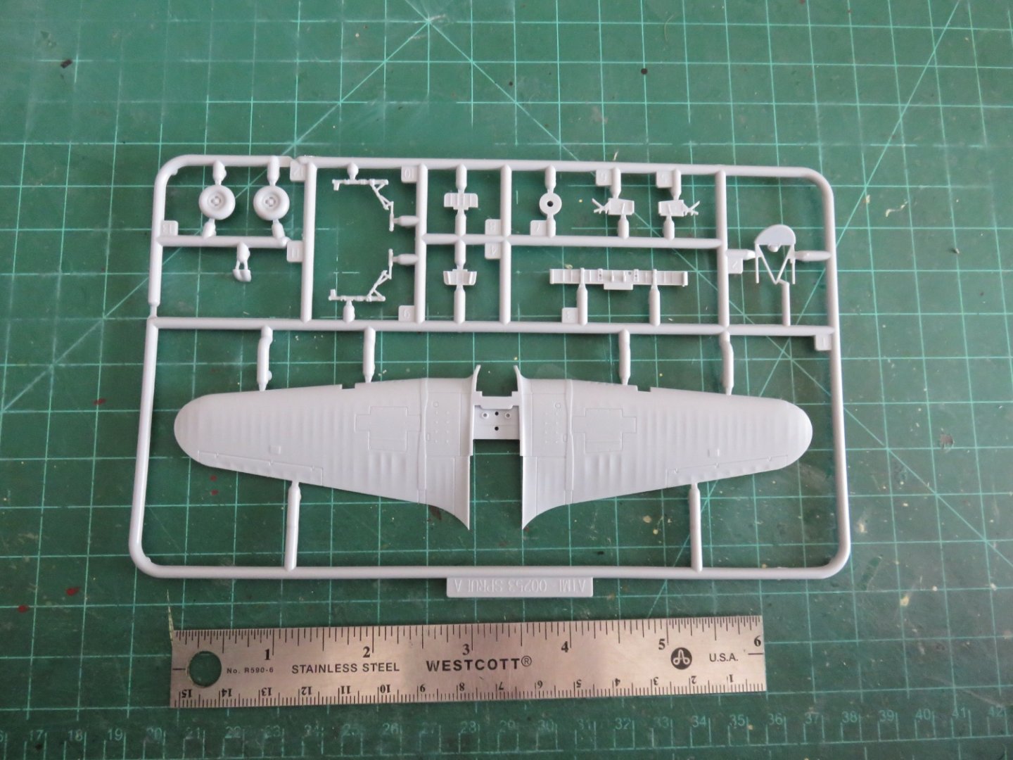
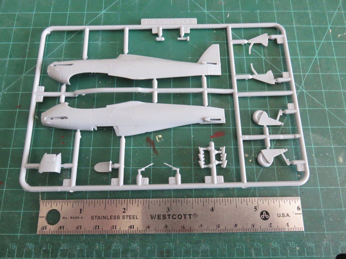
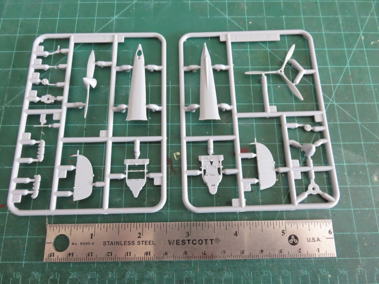
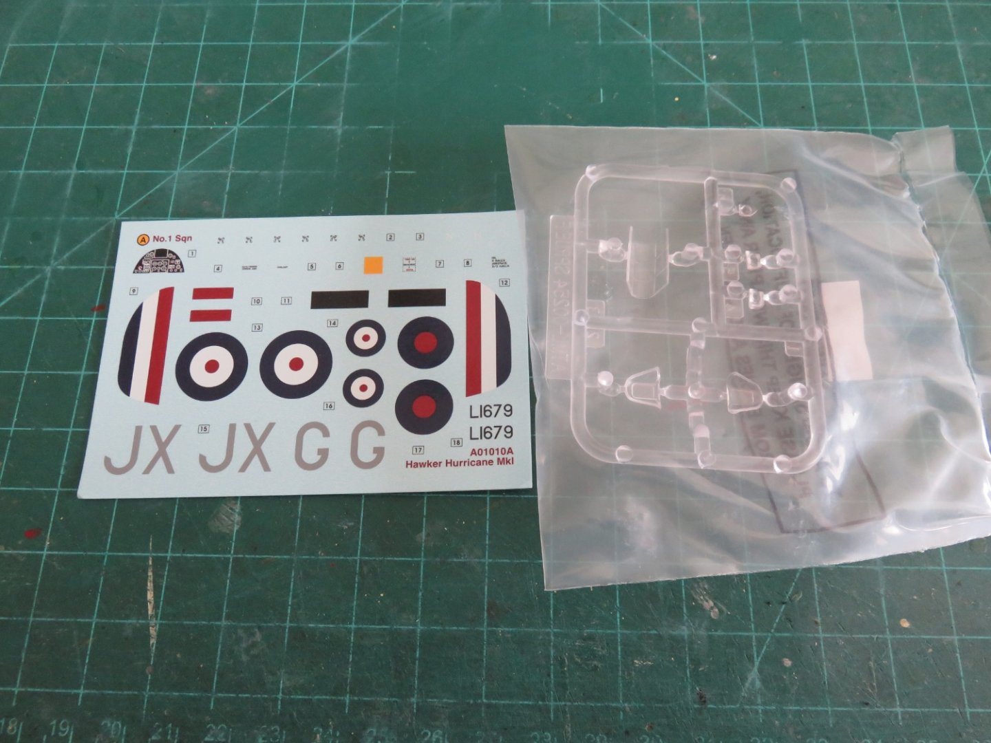
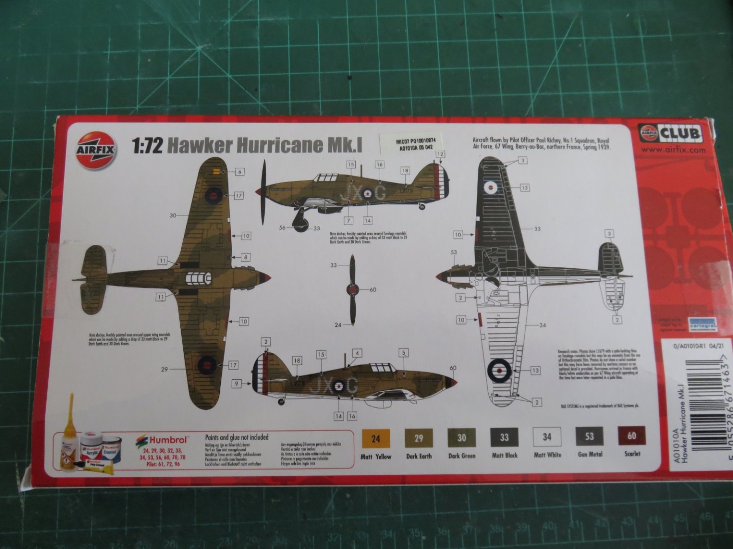
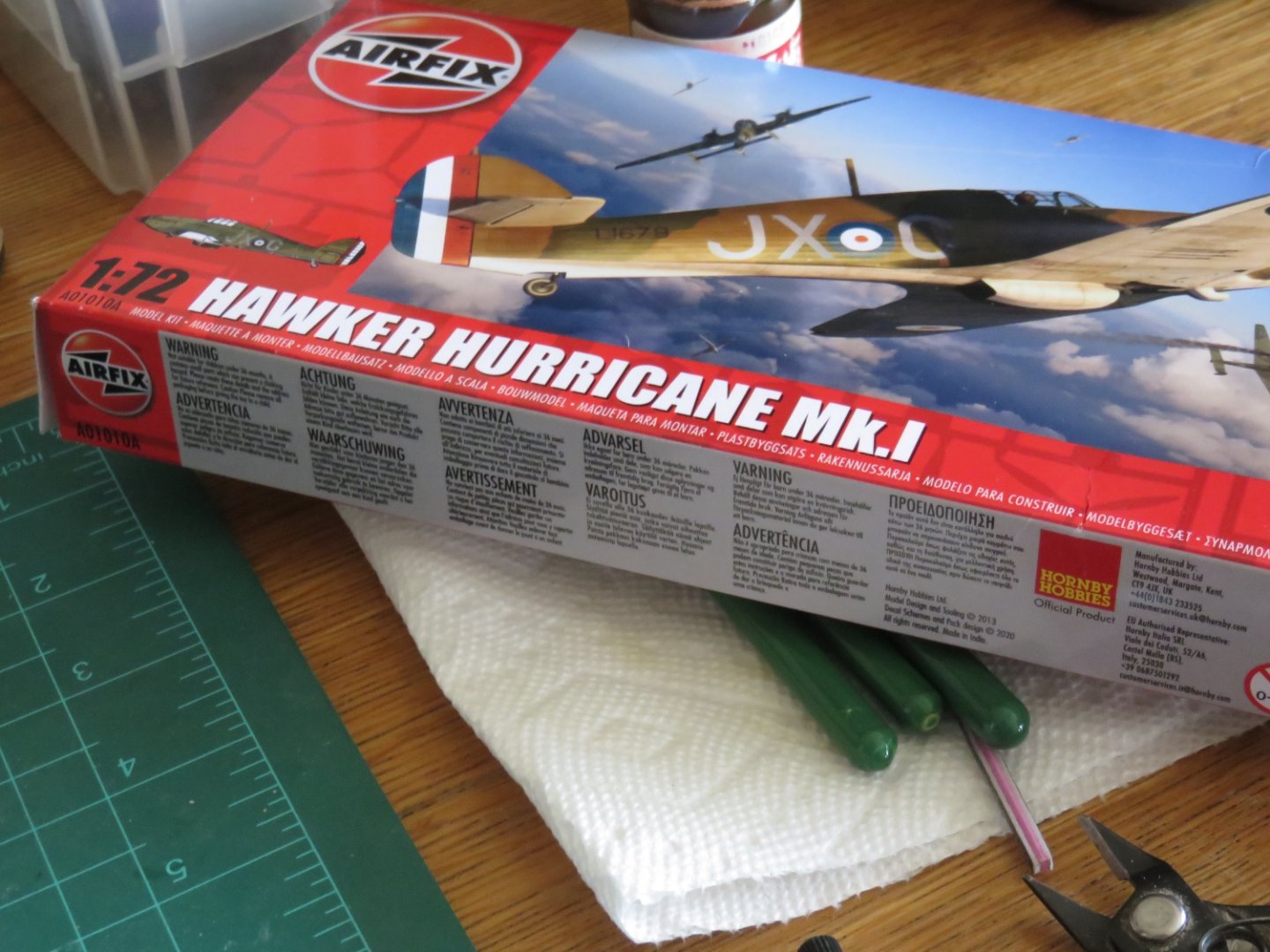
Happy New Year Everybody! OK, so I couldn't wait any longer. Especially since the paint I had ordered, mostly to finish my Wellington, arrived yesterday. For some reason the post office was being extra efficient. Never would have thought they'd deliver on a weekend, but I'm not complaining! For those not following along with my other airplane build, I picked up this little kit back in the beginning of December. The kit depicts an early Mk 1 Hawker Hurricane that was deployed to France in the spring of 1939. For a more complete history of the aircraft type, click here. The kit has the fabric wings, two bladed propellor and lacks the armour plating behind the pilot, that are the hallmarks of this sub-variant. It does, however, feature the spin recovery strake that was fitted at the bottom of the tail. This modification was made early in Hurricane production as spin recovery proved to be an issue with the aircraft as designed. Conveniently, Airfix provides plenty of extra parts in the kit, like the later three bladed propellor as well as the cockpit armour plating etc. Although I intend to build this kit mostly out of the box, I will take a few liberties in fitting out the plane using these extra parts, to suit my taste. Historical accuracy can get stuffed! My main preference is for the three bladed propellor (the two bladed prop is too "biplane" like for my taste), as well I will be using the armour plating in the cockpit. I am also not keen on the early black and white paint scheme on the underside, and I will opt for the sky grey-beige-green (whatever that colour is) underside. There's no real way around this, but for what it's worth, it's a cute little kit. There are five (small) sprues moulded in the usual grey plastic, as well as a small sprue in clear for the windscreen (both armoured and unarmored, although I'm hard pressed to tell them apart) and canopy. The moulding looks clean and crisp with minimal flash or other imperfections. The decals look reasonable, although being from Cartograf, the film will be a little thicker. While this does make the decal more robust, it can hinder it from settling down in higher relief areas. All in all, this should be a fun, quick(ish) little project (the biggest hold-ups being waiting for paint to dry). The nice thing is, while I'm waiting, there's a Wellington that needs finishing! Andy

- 92 replies
-
- 14
-
-
If you could get the figures to look right, I think they would be a nice addition to your barge. But is it just me, or do the screenshot sample figures you posted look vaguely like “The Who”? Andy
- 106 replies
-
- 6
-
-
-
- Admirals Barge
- Vanguard Models
- (and 1 more)
-
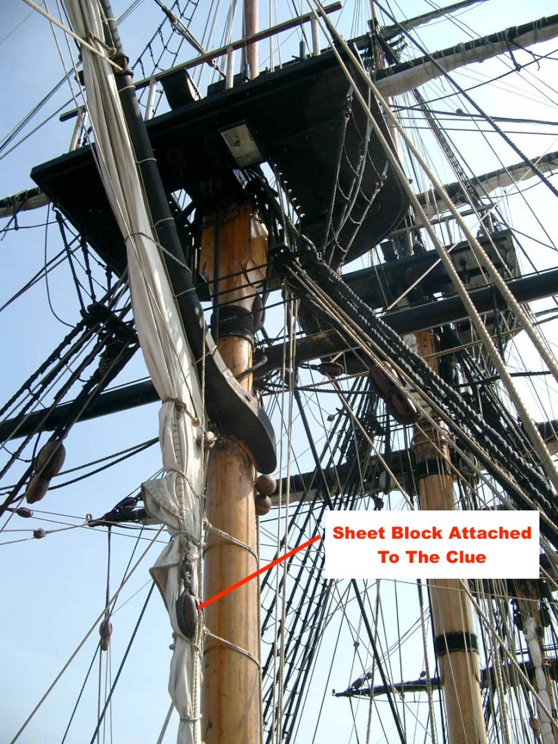
gaff without a driver boom
realworkingsailor replied to DaveBaxt's topic in Masting, rigging and sails
HI Dave, I think this may help,. I think you've got the sheet and tack confused. If you don't mind, I've annotated your first two photos, hopefully they help clarify things a bit for you: In the first photo, the sail is brailed up and what you seemed to think was the tack, is intact the sheet block. In the second photo, the tack of the sail does not move when brailed up. It would be located somewhere in the vicinity of the lowest lashing on the mast. There may be a small tackle or downhaul lashing obscured behind the fall of the brails and the sheet. The other sheet block has been brought forward and secured to an eye at the mast partners, and the sheet haul taught and secured to a free cleat on the mast. Hopefully that helps you. Andy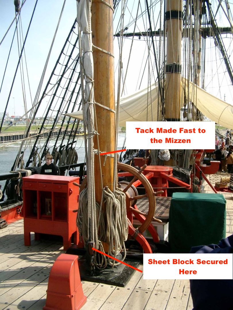
-
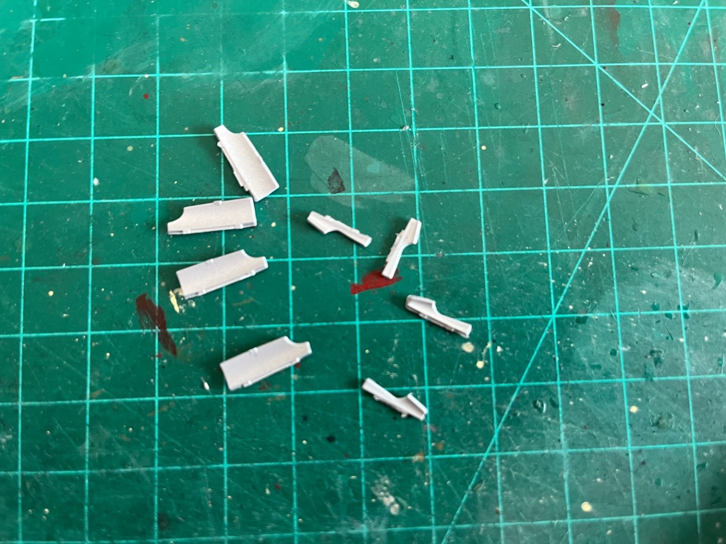
Thanks everyone for the “likes”! I’ve been thinking about the landing gear doors. As I alluded to earlier, I’m not entirely satisfied with the Eduard replacement parts. I think I’m going to follow my own advice. Luckily I don’t throw out anything, especially “spare” parts: It’s always a challenge, especially with that little gremlin who loves to gobble up small parts, especially the ones that fly off in all directions (or roll off the work bench), but I’ve got all the original parts. I will definitely lose the fine cross section of the brass PE parts, but I think it’s a fair trade for more securely attached parts, as well as ones that will actually appear to fill the openings. Andy
- 174 replies
-
- 10
-
-
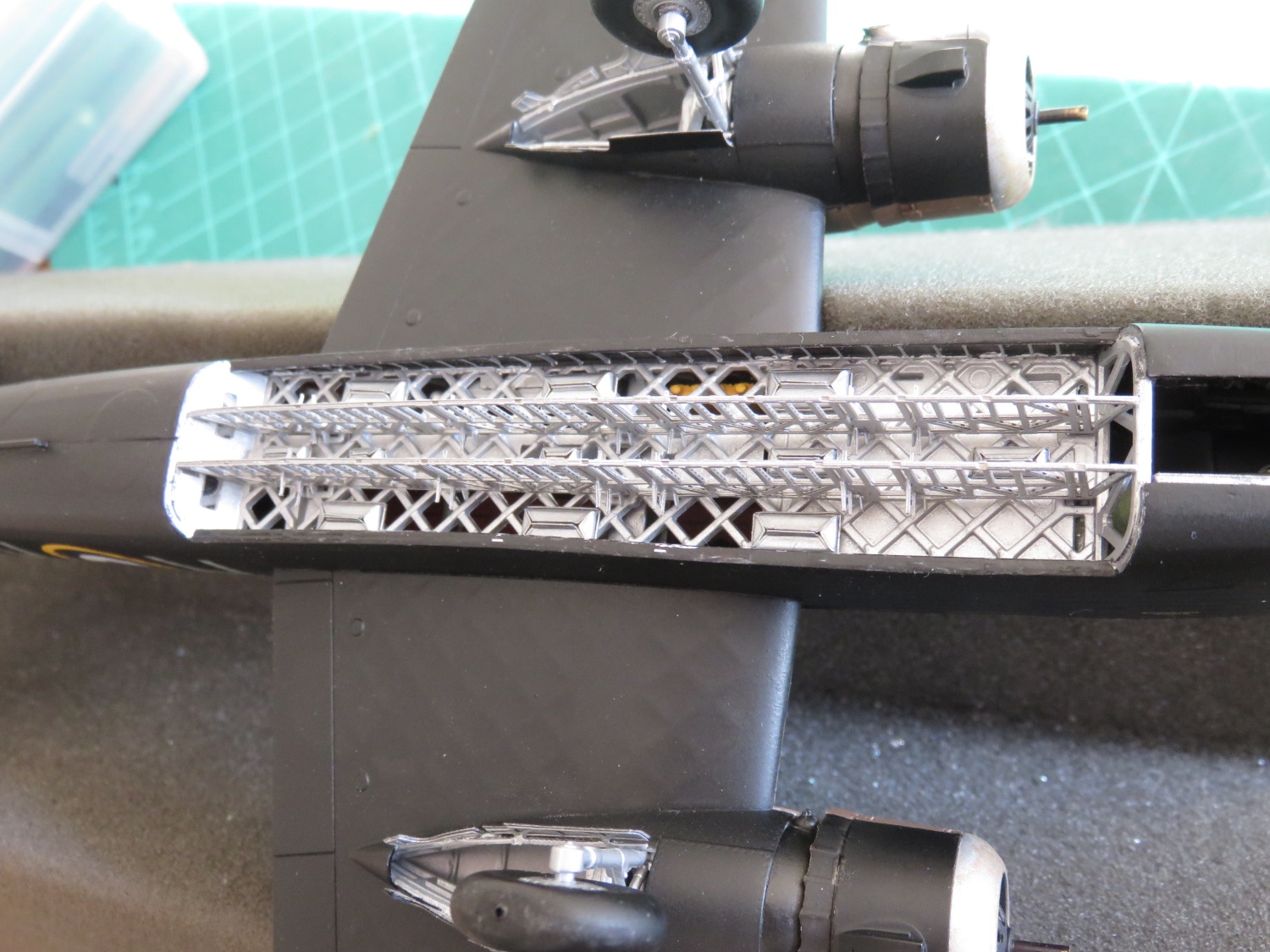
As always, thanks to everyone for their generously kind comments and continued "likes"! Not being a regular airplane model guy, it's reassuring to know I am at least doing this model a modicum of justice! I have been intermittently busy these last few days, of course the pre-Christmas craziness does tend to interfere with model building. I've been slowly picking away at the landing gear doors. It has been an interesting challenge and I'm not totally sold that the Eduard parts are as good an upgrade as they could have been. There are a couple of issues, the first being the mounting isn't the strongest; a tiny tab on an thin flexible strip to hold the doors. Secondly, the instructions once again are not as clear as they could be. An interpreter of Egyptian hieroglyphics has an easier job of it. Eduard could at least add one or two detail shots to indicate that the little metal tab sits in an almost invisible tiny slot, and also clear up exactly how the annoying little strip is actually supposed to be glued to the underside of the nacelle. Finally, once again, someone didn't read the tape measure correctly, and the Eduard doors are too short to completely cover the landing gear bay opening. It's not too noticeable, if you didn't look too closely, but as the building, I know it's there. Were I to do this model again, I would be more inclined to keep the kit supplied main landing gear doors and use some of the Eduard parts, specifically the interior framing to, up the detail level. Oddly enough, there were no issues with the tail gear doors. But there again, just three little tabs to hold each door in place. The last major components to be assembled are the bomb bay and bomb bay doors. This has kind of brought the build full circle, as these were some of the very first parts I assembled way back when, and carefully stored away for when the time was right. The bomb beams were slotted into place perfectly after the cases for the buoyancy bags were installed. I had hoped to have things wrapped up by Christmas, but I have run into another of those annoying snags. This time, I've run out of aluminium paint. *sigh*. Not sure why that is, as there really wasn't a lot of the plane that colour (compared to the amount of black, brown and green paint I used). As usual, supplies have run out when I was in the middle of painting the bomb bay doors. Looks like I will have to put in another order for supplies, but I won't be doing that until after Christmas. Too much going on and I need to spread the holiday bills out a little bit! 🤪 Andy


- 174 replies
-
- 11
-
-
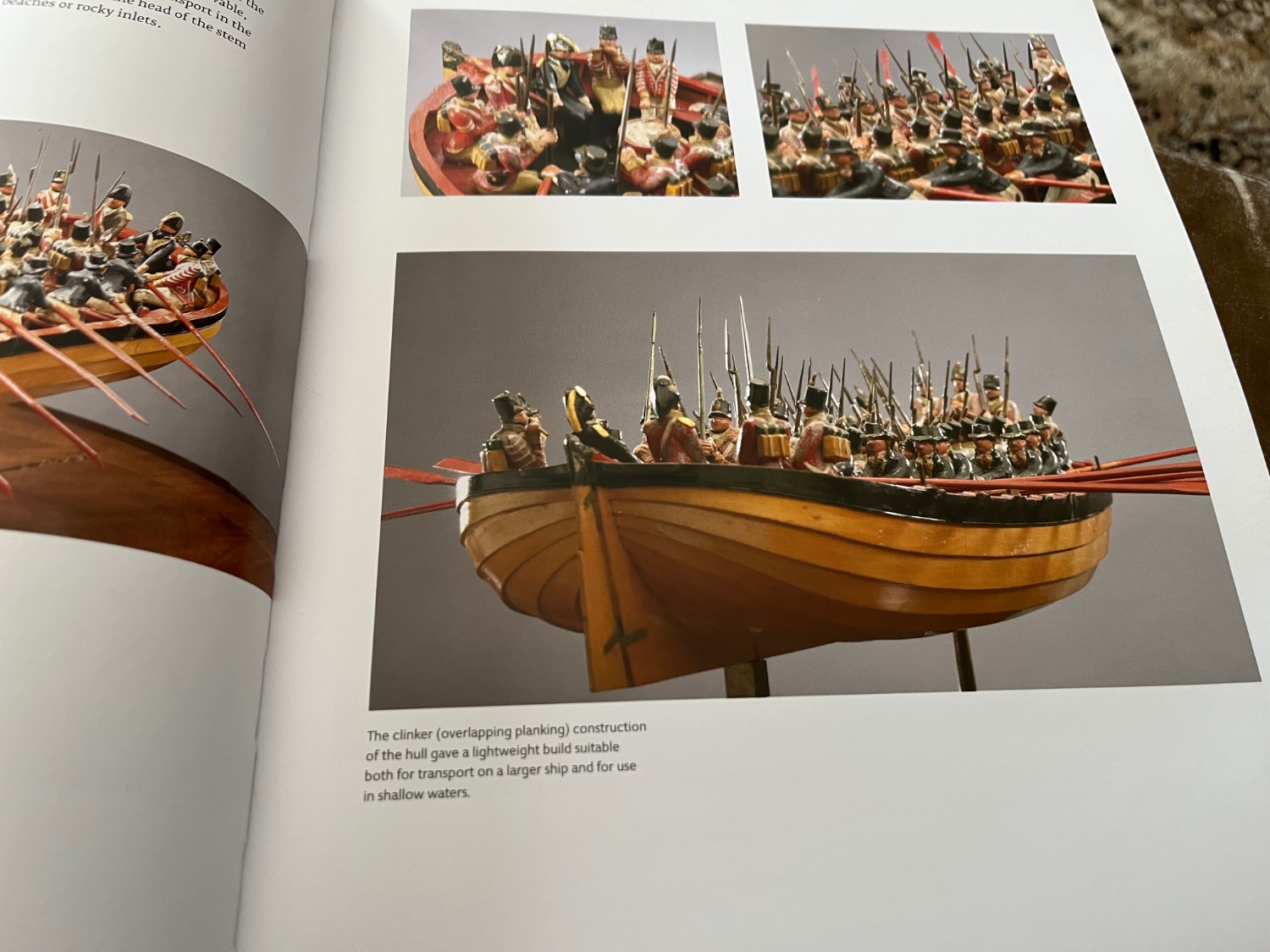
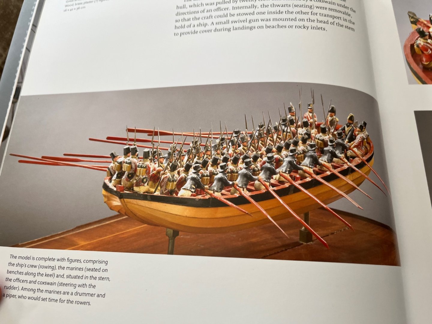
If you’re still brainstorming for ideas, this kinda intrigued me: Mid 18th century landing craft. Photos from pp 30, 31 of the book “Ship Models, The Thomson Collection at the Art Gallery of Ontario”. Not sure if any plans still exist, but it struck me as an interesting subject. (It’s not a yacht! 😁) Andy

-
Have you tried Walthers? https://www.walthers.com/products/accessories/scratch-building-supplies/plastic/manufacturer_name-plastruct_inc Andy
-
Thanks! No stressed skin on this old bird, just old-school doped fabric on a metal frame. The fabric was layer directly on the wing frames, whereas the fuselage had wooden battens between the fabric and the frame. One of the advantages of the Wellington design, there wasn’t as much weight given over to the plane construction, so it could carry a larger payload; the Mk 1c was rated for 4500 lbs of bombs. Yeah, Airfix has done a great job with the detail in the mouldings, way better than the earlier offerings (I remember building their Wellington Mk III back in the ‘90s, there’s no comparison). Andy
-
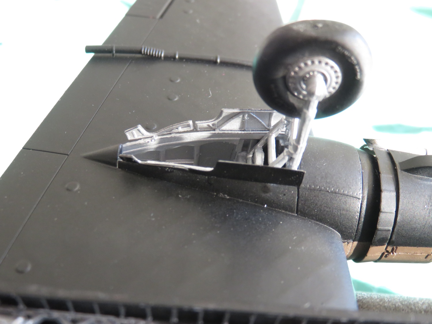
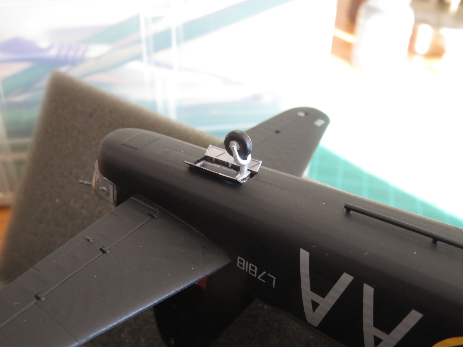
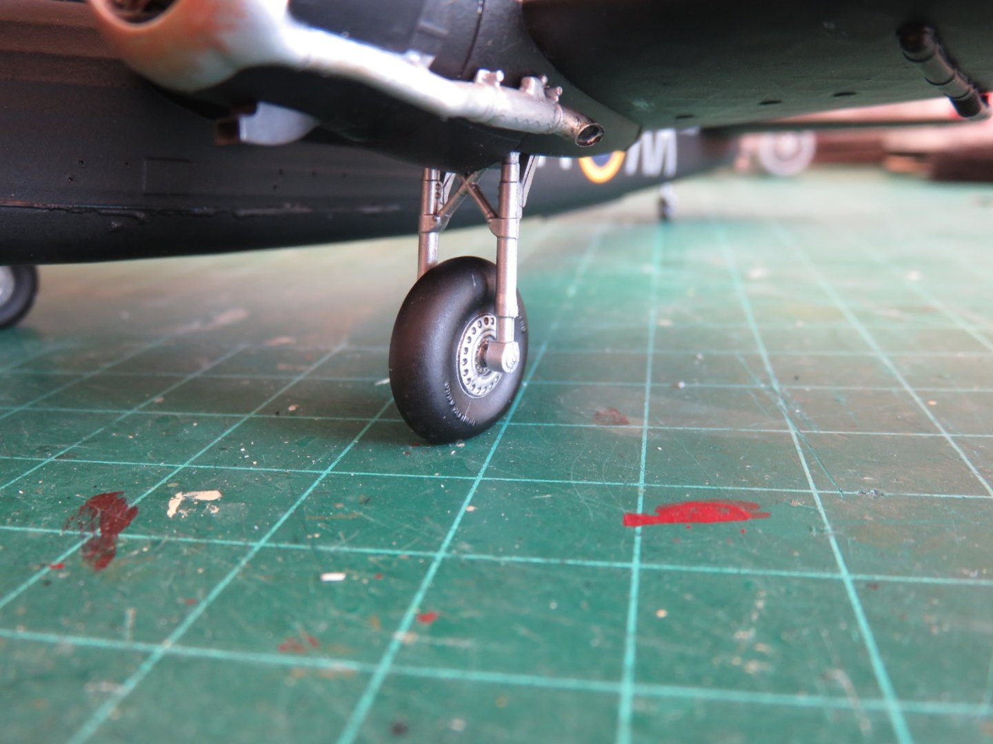
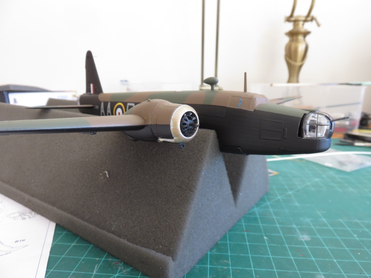
Thanks, everyone, for your continued kind remarks and likes! She's got legs! While the main landing gear struts are from the kit, the main wheels and tail wheel/wheel strut are aftermarket from Eduard/Brassin. There is no real difference between the resin and styrene tailwheel castings, but the main wheel replacements have the "Dunlop Aero" stamp on the sidewalls, whereas the kit supplied wheels don't. The main wheels themselves actually snap fit into the strut, so they can spin, but they include a flat spot to simulate the weight of the aircraft bearing on the tire. The left engine is just dry fit for the moment. I'm going to leave the remaining panel off to show off some of the parts, as if the ground crew had some work to do on the engine (probably some adjustments to the timing, as the distributor was located on the right side of the engine). I have a little touch up work yet to be done on the engine paintwork and the left engine can be glued in place. Following which I can begin working on the landing gear and bomb bay doors. Andy


- 174 replies
-
- 13
-
-
Was the prototype one continuous bent pipe or was it joined segments? Have you considered trying Plastruct tubing? If it was a segmented pipe, they also make elbows (90 and 45) in a variety of sizes: https://www.plastruct.com/collections/tubing-amp-fittings-2/butyrate#MainContent Otherwise you could try gently heating and bending some solid styrene rod of the correct diameter. I’ve done that before by gently holding it near a hot soldering iron until it becomes malleable enough, but not too soft to melt into goo. Andy
-
Although I foresee more fiddly bits with the landing gear and bomb bay doors, I’m too close to finishing to let something like that hold things up! 😁 Andy
- 174 replies
-
- 10
-
-
Thanks guys! Looks like the left engine cowlings have the same issue. I really shouldn’t be surprised, but knowing there’s a workable fix, I’m a little less disappointed. Of course, if I was to leave the middle cowling open to view the engine, I wouldn’t have to bother with the fix…. Until some wise guy thinks to check with a measuring tape… hmm…. Andy
-
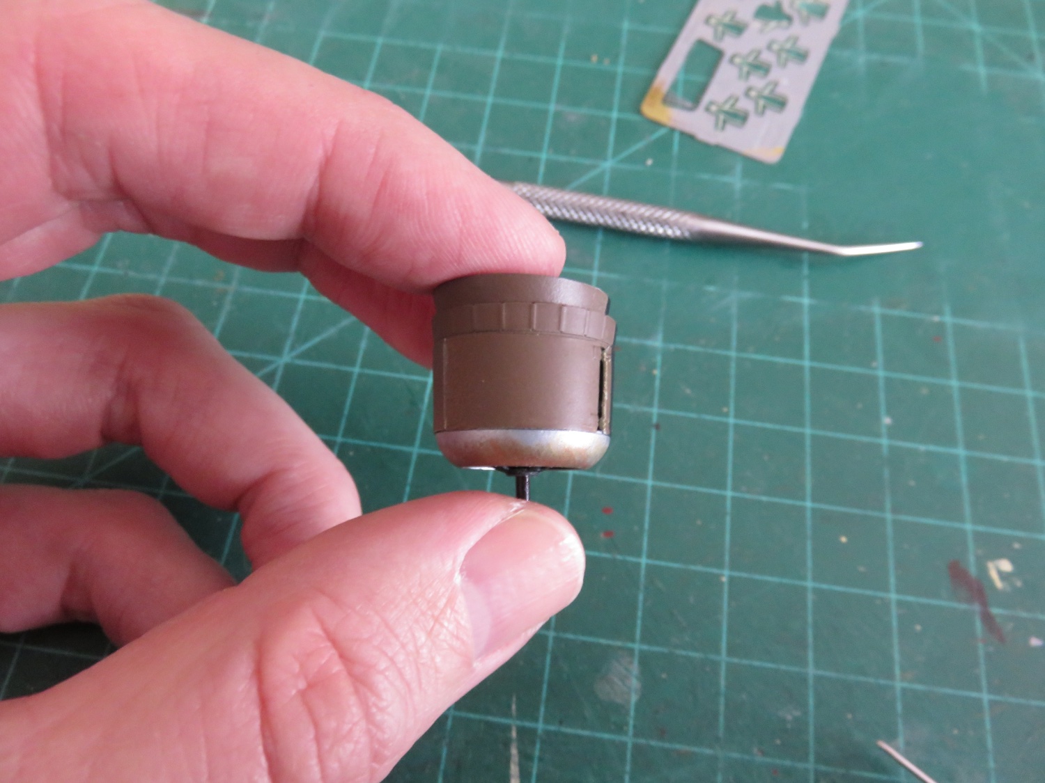
Thanks everyone for your words of encouragement and suggestions. I am pleased to report that we are now flying on one engine... no propellor, but we've got an engine! The insert is barely noticeable, it's located at the seam on the engine cowling at the 11 o'clock position. This seam is by design, as the engine cowlings are composed of three separate panels. A little weathering and some Dullcote and things will be just fine. Onwards! Andy
- 174 replies
-
- 12
-
-
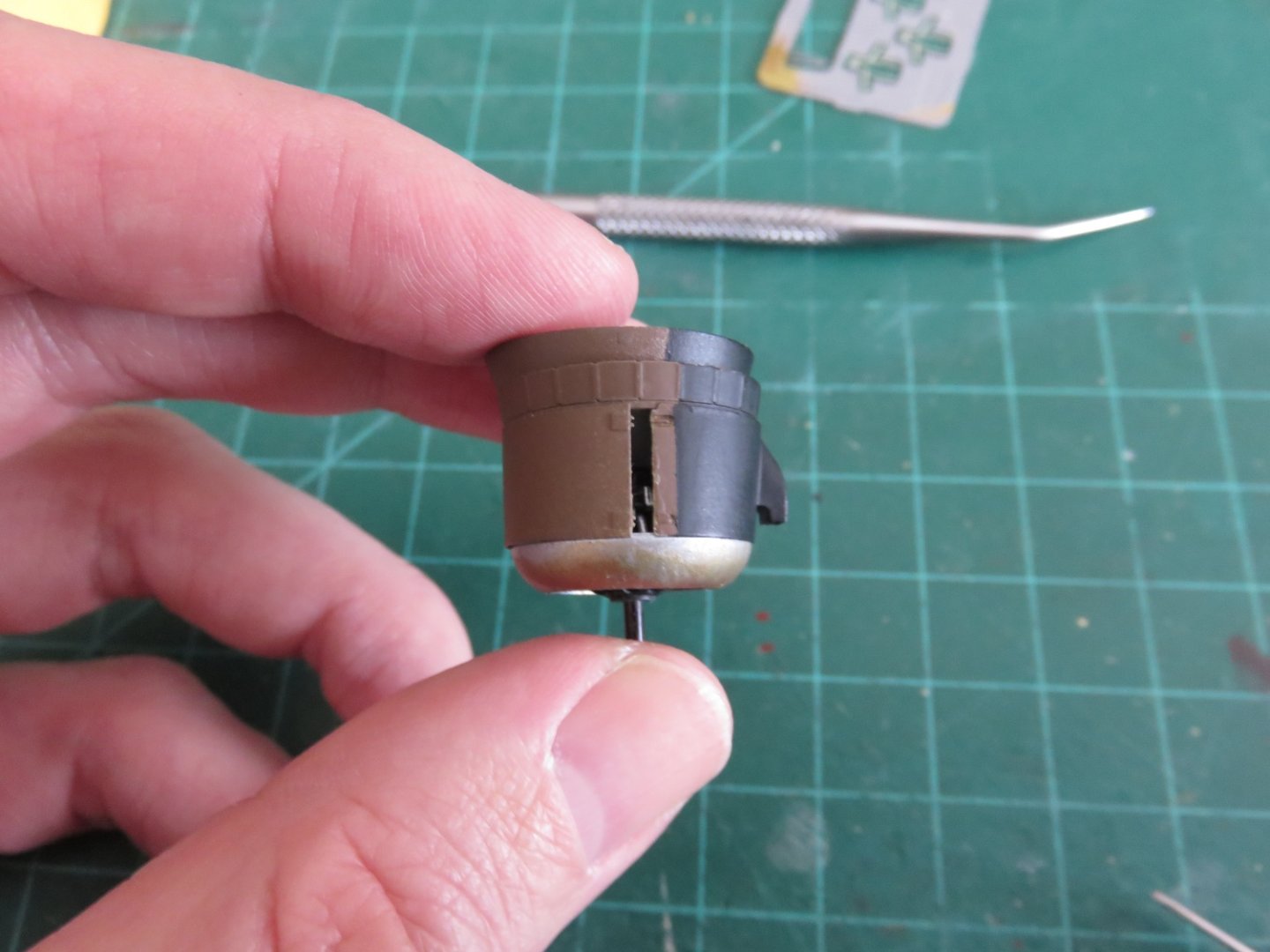
I have some thin strip, I believe 0.010”x0.060”, that should work. I don’t think I have to split the piece, the latch detail is only on one end, the other just has some raised bumps suggesting interior hinges. I’ve glued the piece with the latches together, so the gap is now on the other side compared to the photo above. All I will need to do after inserting my filler is hide the seam. I hope 🤞 Andy
-
Well, this is somewhat disheartening... I think someone didn't measure right, or rounded pi wrong.... Eduard... I'm looking at you! 🤨 Oh, yeah, and those engine mounting brackets.... Yeah... that's not gonna happen either, that's a level of finicky that I am ill equipped to deal with (in regards to tools, patience and sanity). I will attempt one more time on the other engine (maybe it will be easier if I change the order of operations a bit and do the brackets first before installing the fin ring. I dunno... We shall see. In the interim I have this problem now to solve as well. Time to break in to my styrene stash. Hopefully this won't fix won't end up looking too ugly...... Andy

-
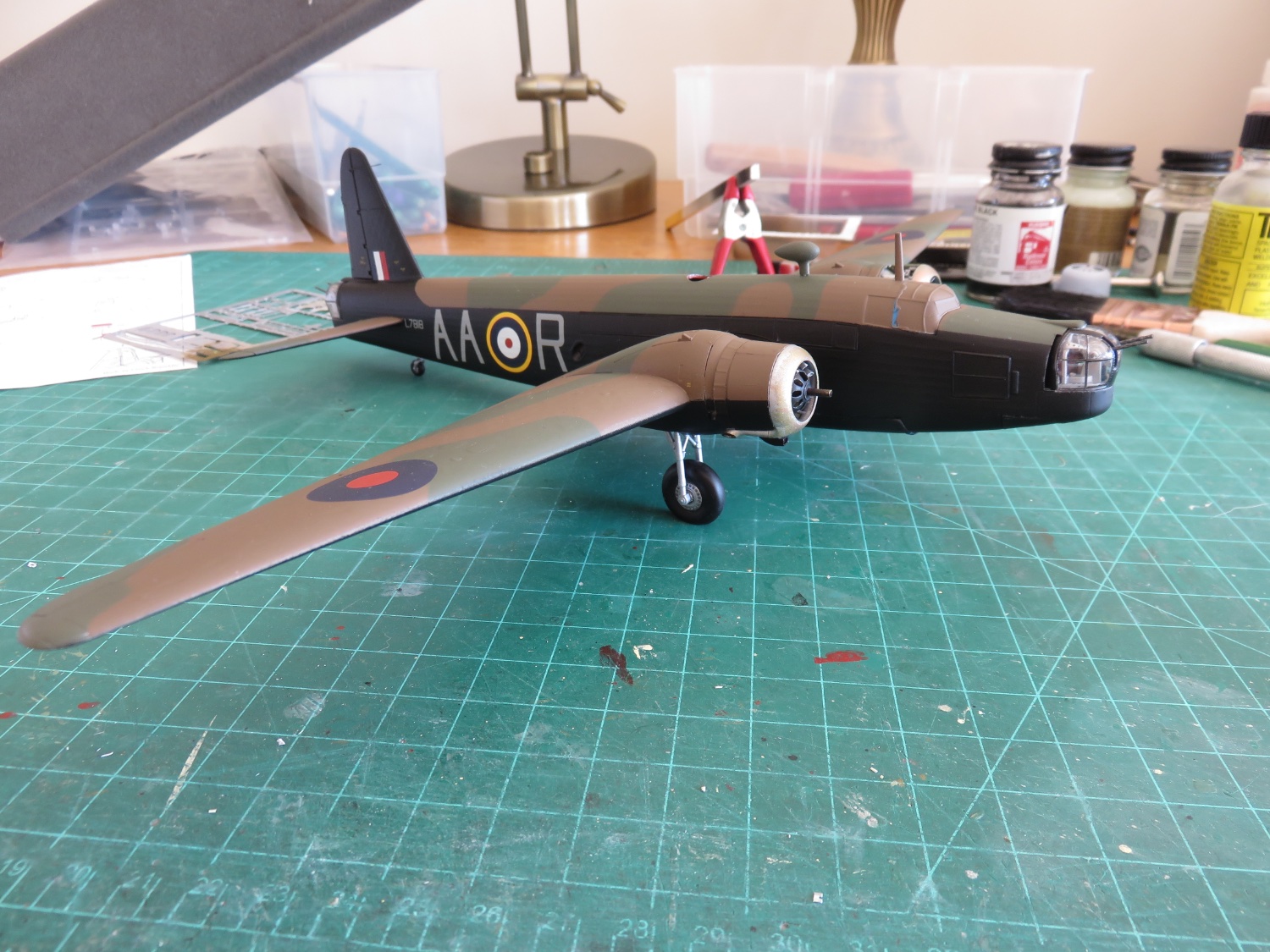
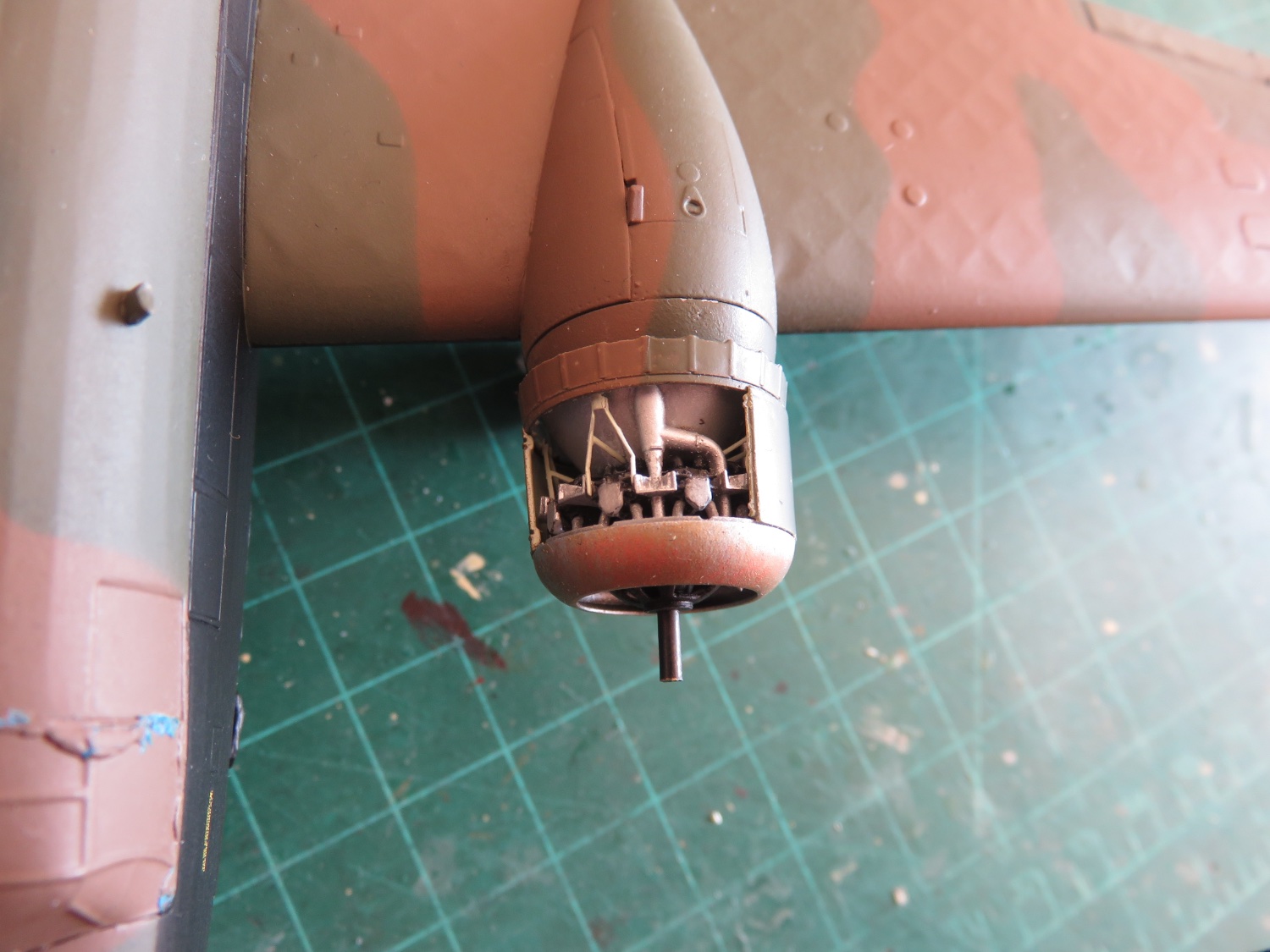
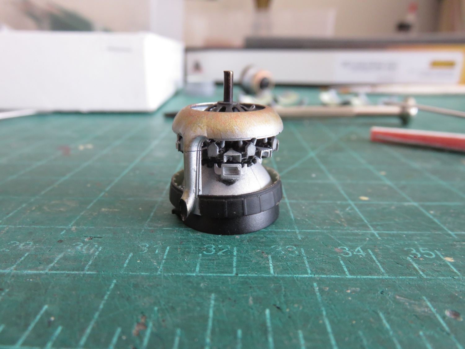
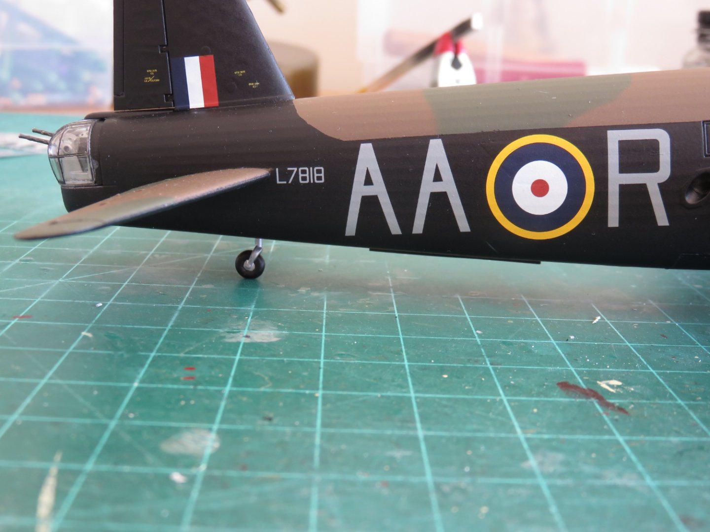
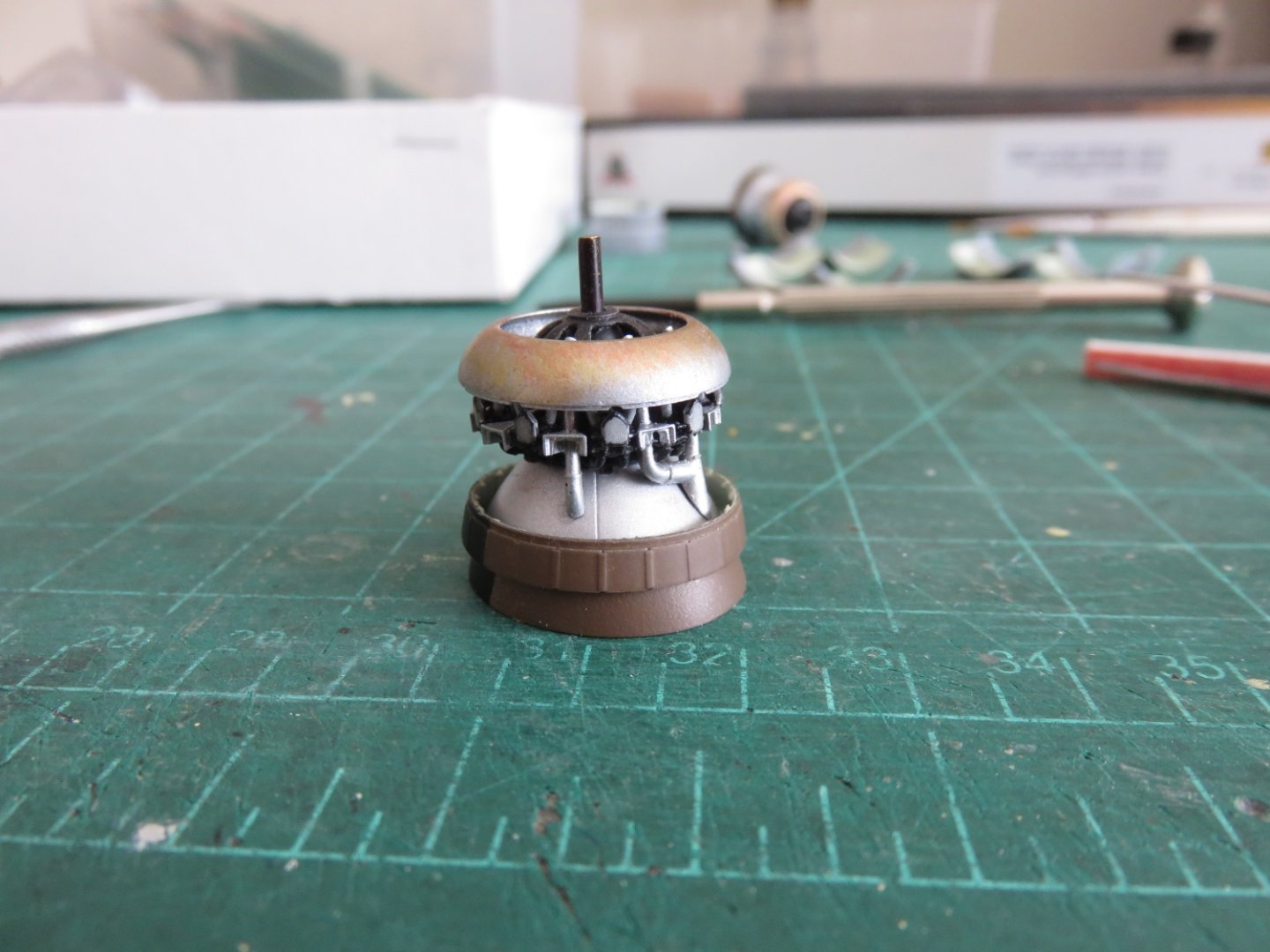
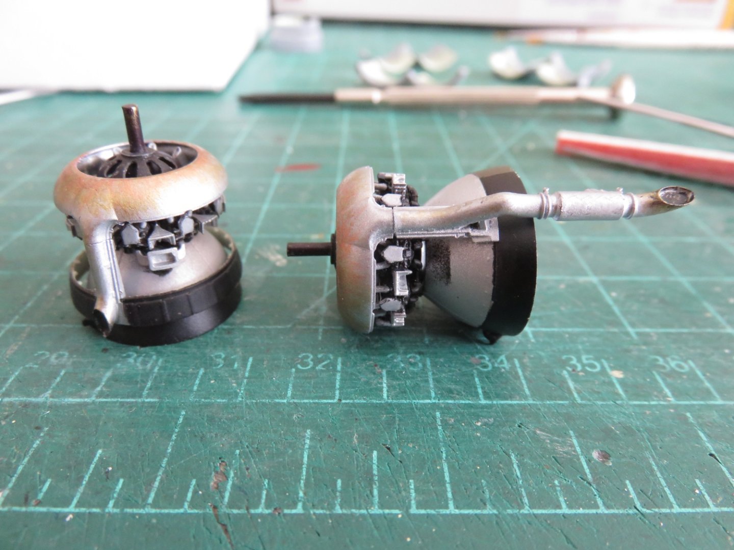
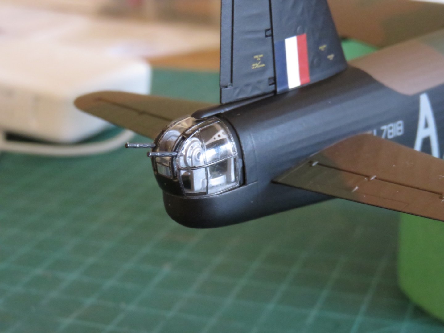
According to the box info, this one was in the Battle of France (given the red/white/blue fin flash was located on the rudder itself, French fashion), but if it survived that one, I'm sure it was involved in the other. For lack of a better descriptor, it's a cute little kit and I'm looking forward to getting in to it. I will build it mostly out of the box, but seeing as there's parts for different versions, I may mix and match a little bit here and there. I'm thinking of taking a few liberties with the paint job, I prefer the sky green underside over the black and white, and I'm going to attempt to restore the yellow outer ring to the fuselage roundel. More on all that when the time comes! Thanks everyone for the kind comments and likes. I'm getting back underway with the engines, now that I can get the various components primed and painted. First up the right engine: After fitting the fin ring, there are various plumbing pieces on the top, which I think have some function with the supercharger, as well as the carburetor located underneath: Next up is to add all the finicky little engine mount brackets, and then the cowlings. I plan on displaying this engine with the cowlings closed, so any errors made when figuring things out will be hidden. I've already begun picking at the left engine. Out of the factory, for whatever reason, the left engine had a longer exhaust pipe than the right. Later on the right engines also received this extended exhaust pipe, and later still both engines received the hedgehog-like diffuser found on the Bristol Hercules engine (hedgehog like the animal, not the ASW mortar). Andy

- 174 replies
-
- 10
-
-
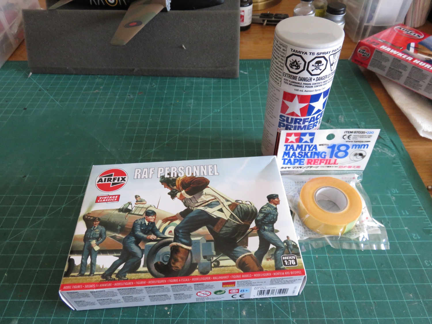
Thanks, guys, for your kind comments! And thanks to everyone for the "likes"! So, a bit of good news, I few supplies showed up today, including a can of Tamiya primer, yay! I needed some wider masking tape as well, and I got a set of RAF figures to help "flesh" out my plans for displaying my Wellington. Some time in the new year I will look into getting the RAF bomber resupply set and.. I... uh... HEY! What's that in the top right background?! How did that get there?! Sigh..... ah well.... 🙄 Andy

- 174 replies
-
- 11
-
-
-
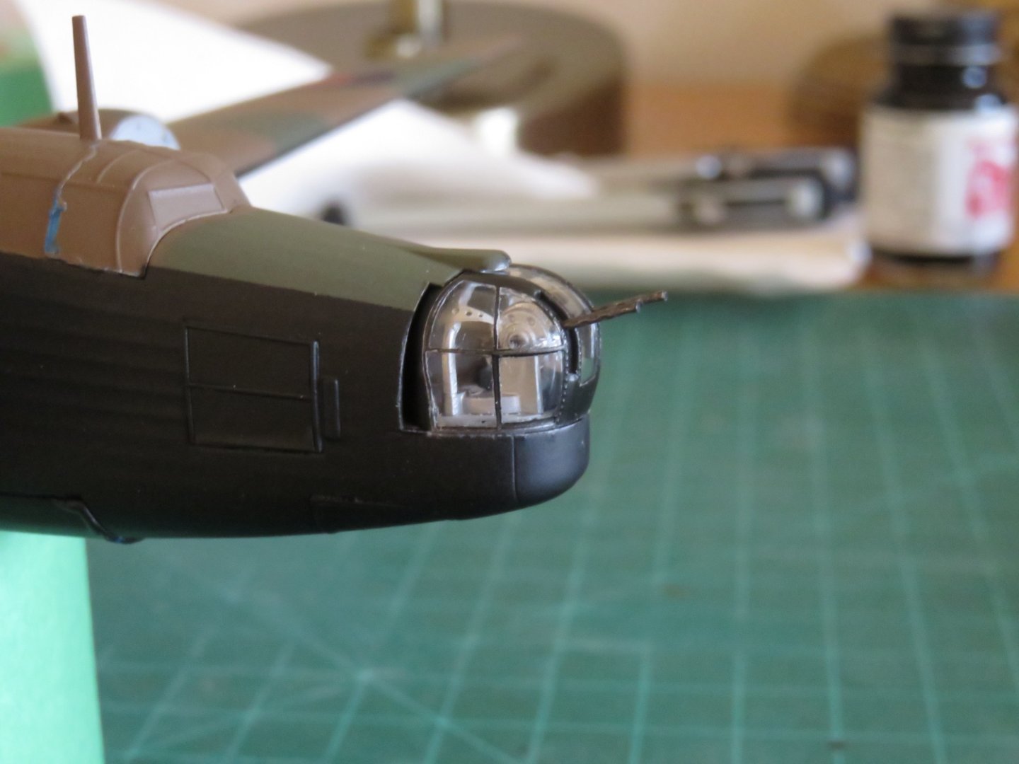
Thanks, everyone for the continued "likes"! Just another small update to show that progress is still being made. The nose and tail turrets have been built and installed. Depending on how I weather the plane, I may yet need to add another coat of Dullcote when all is said and done, so I have not yet fixed them permanently, and I may leave it that way. They fit quite snugly into place (they're not going to randomly drop out), and, although they're not designed to rotate freely, I'd rather maintain a little flexibility. When I painted the clear parts I made a conscious decision to avoid using primer (despite the fact that I had run out, I never planned to in the first place). To a degree the opposite inside of the "glass" is visible, so instead I used a silver/aluminium base layer, followed by a black top coat. This allows the inside to appear "metal" rather than primer grey, as well through incidental handling, the silver on the various rivet heads and sharp areas became visible as the black was slightly worn off, giving it a bit of a weathered look in places. I've seen a few prototype photos where the black paint appears to have been fairly well worn off (chipped or otherwise blasted off), so a little silver highlighting is not uncalled for. I followed the same approach for the cockpit canopy (although with a brown top layer), to the same effect. I will hold off on that installation as well, until the last moment. Andy
- 174 replies
-
- 16
-