DONATION DRIVE - SUPPORT MSW - DO YOUR PART TO KEEP THIS GREAT FORUM GOING!
×


realworkingsailor
-
Posts
3,271 -
Joined
-
Last visited
Content Type
Profiles
Forums
Gallery
Events
Everything posted by realworkingsailor
-
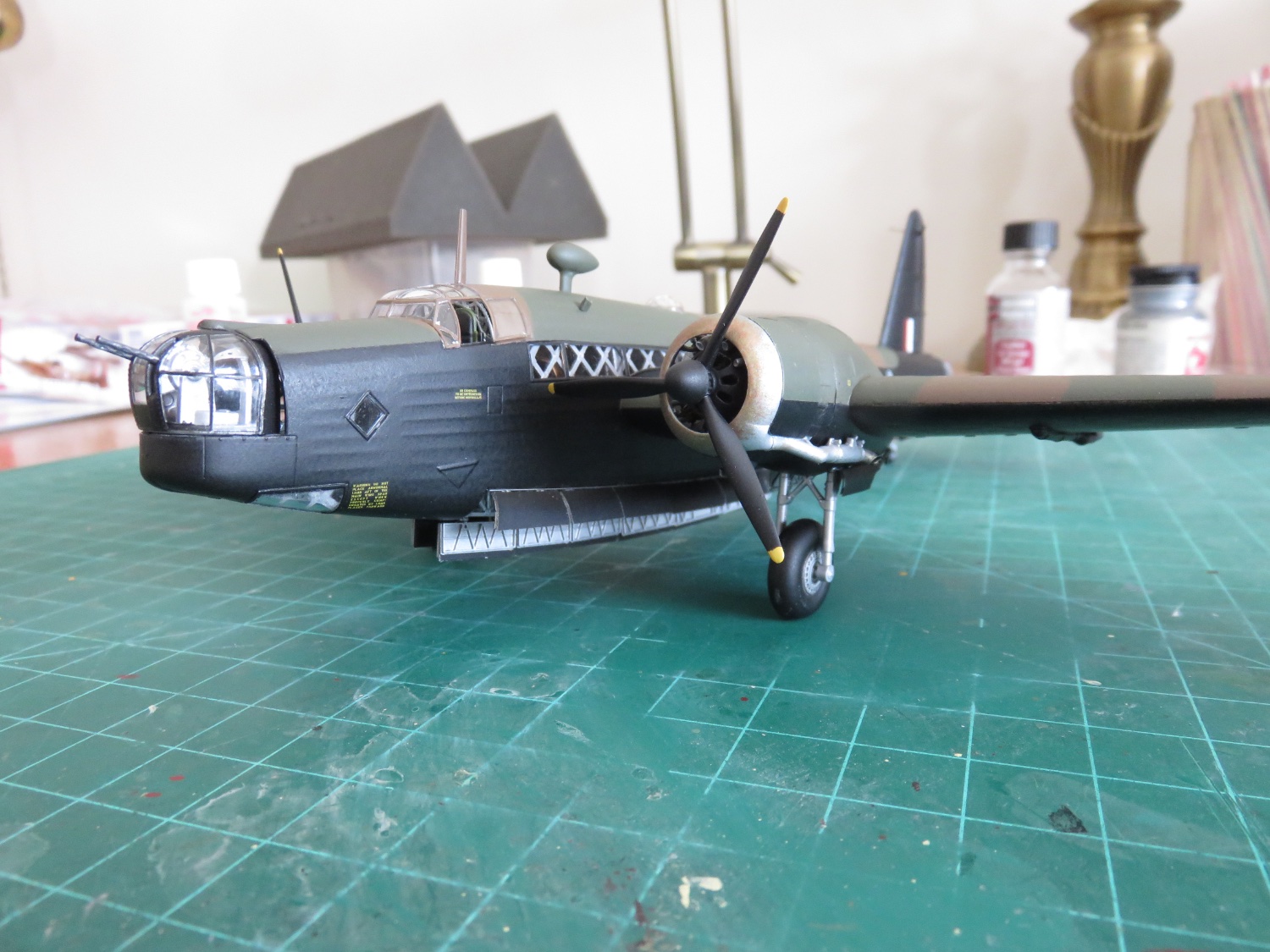
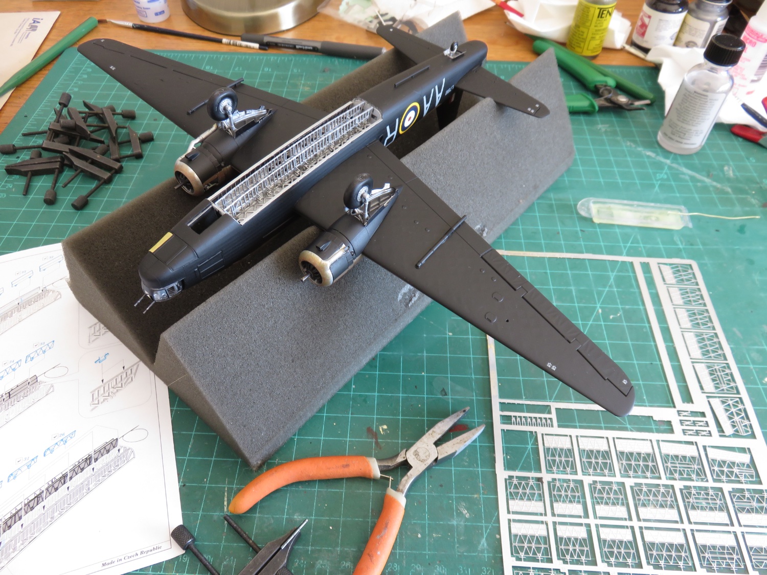
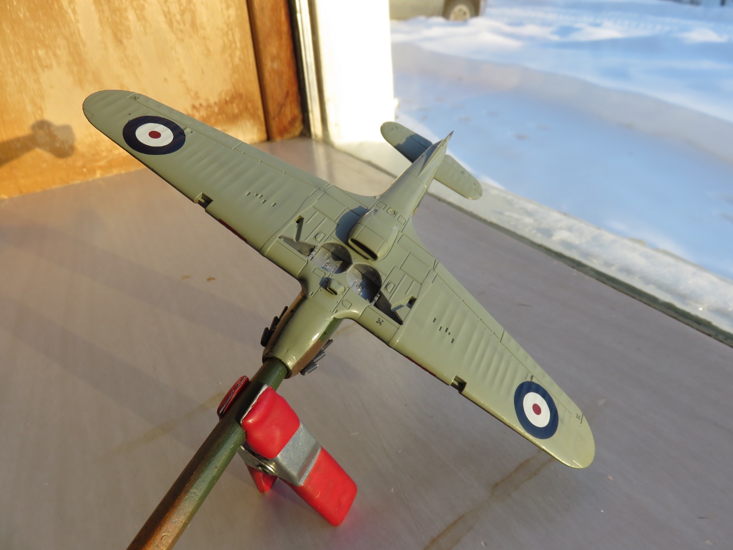
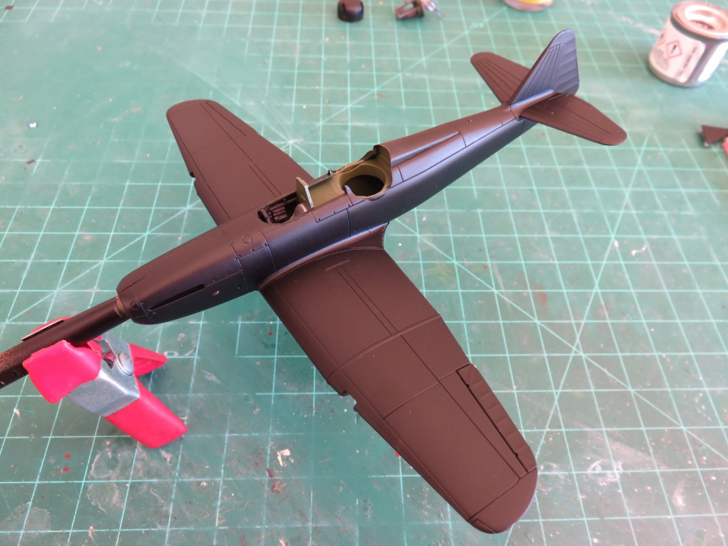
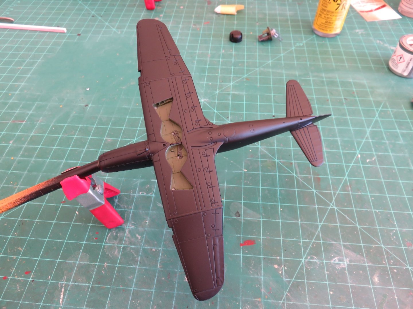
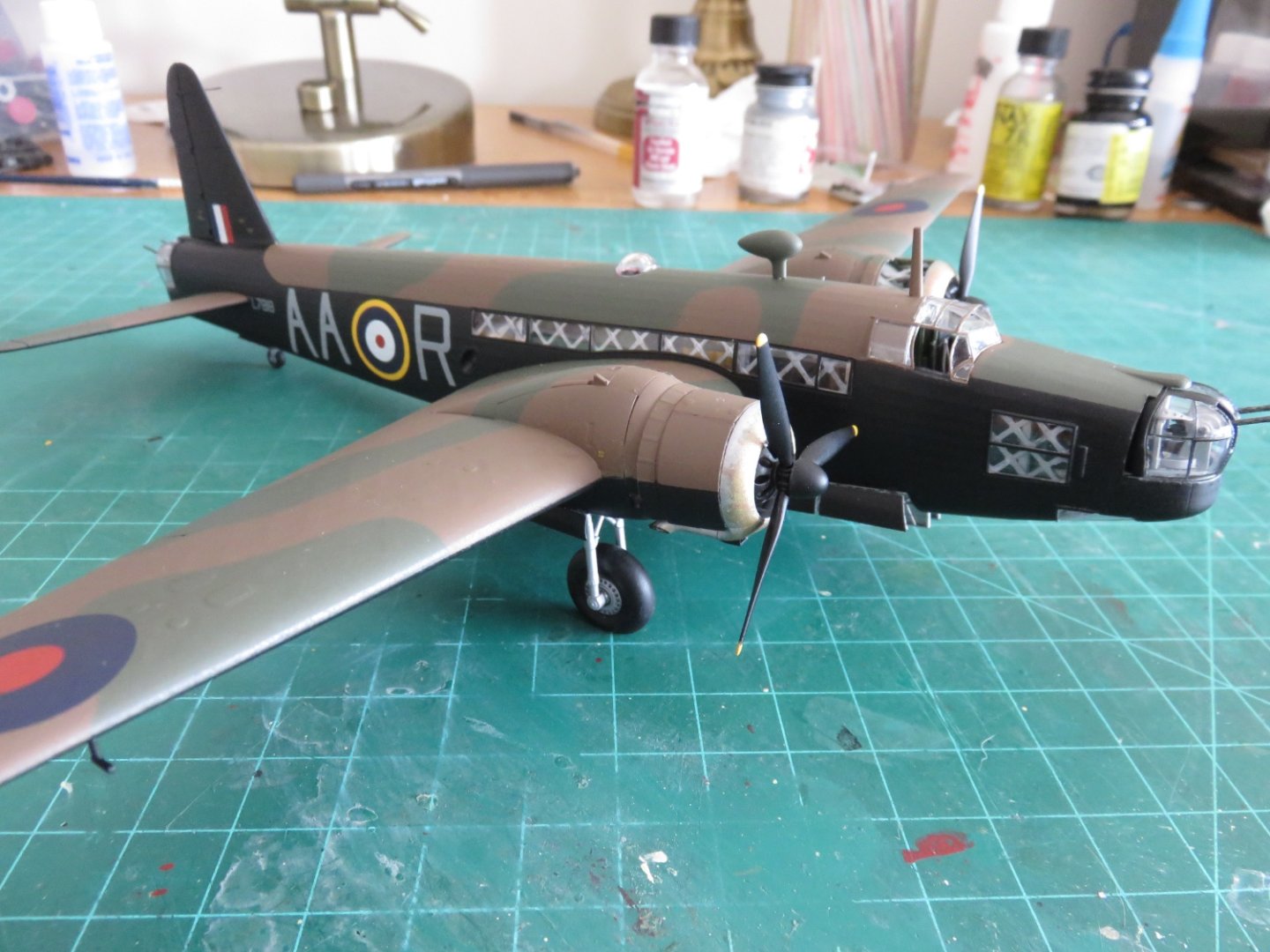
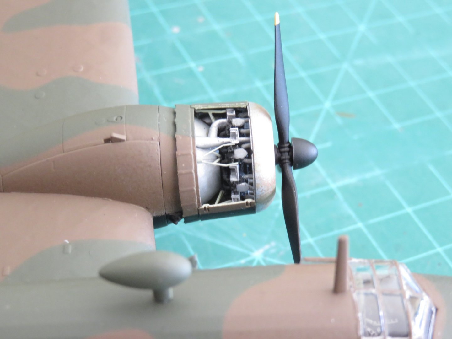
 Thanks for all the likes, everyone! Painting has begun in earnest. Although being a simple scheme, it hasn't taken too much time and effort. I feel a little bit like Henry Ford... "You can have it any colour you like as long as it's black" I think it's going to look quite striking when it's done. The monochrome colour scheme really focuses the attention on the details of the aircraft. I'm really pleased with the way the landing gear bay came out: Prototypically, yes everything is supposed to be black, but I like this look better. I am currently working on the radiator and air intake cowlings and they will be attached soon. Afterwards a layer of gloss and it will be time to begin the lettering process. There is a ton of stencils to go on this airplane. The gang at Boulton-Paul were a little obsessive with labeling apparently. I wonder if they had a "label maker" label on their label maker...... Andy
- 36 replies
-
- 11
-

-
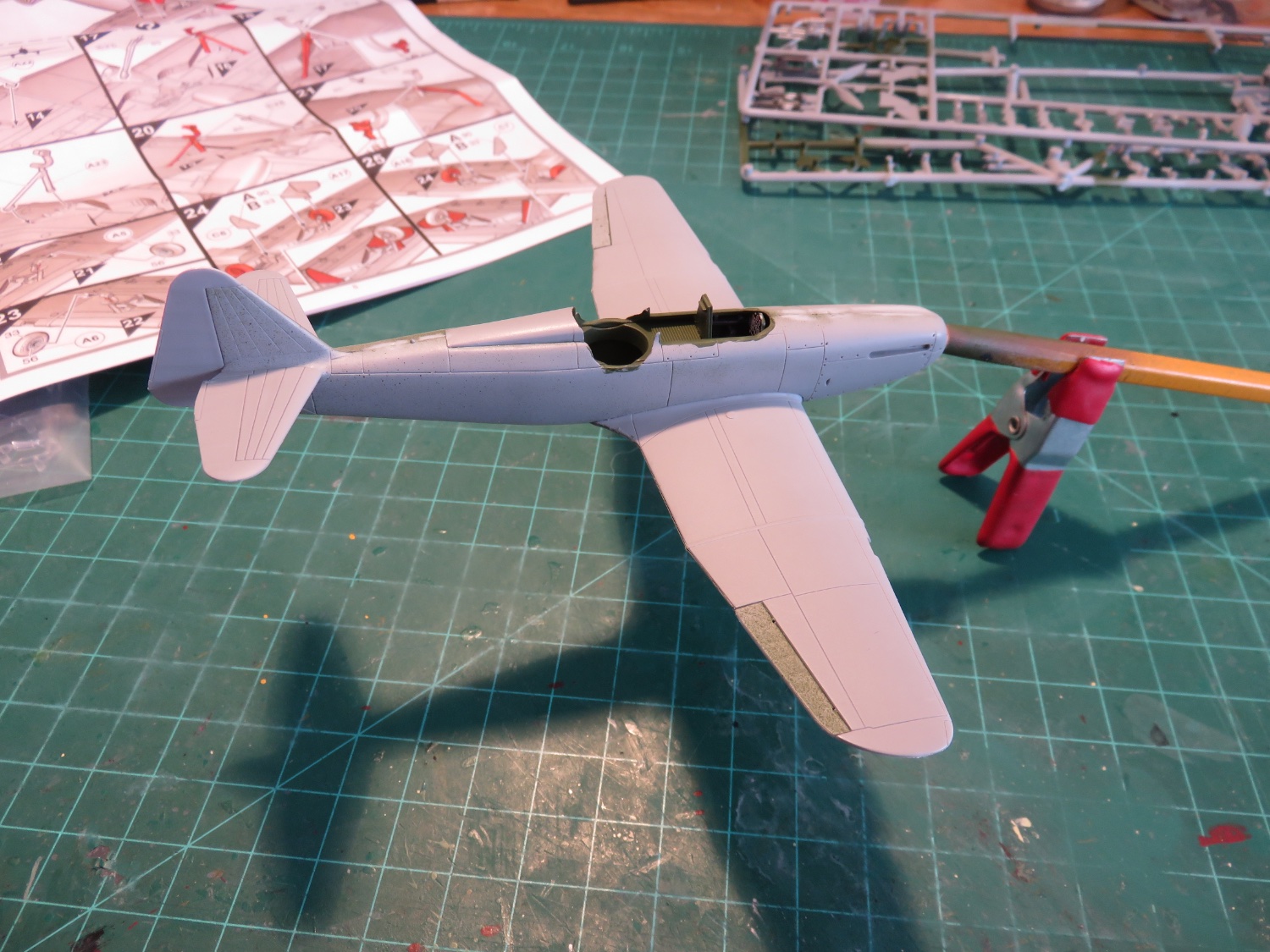
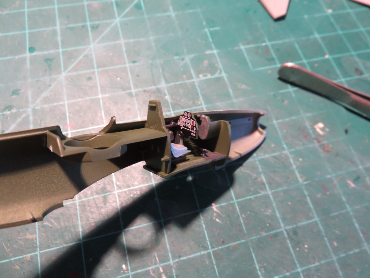
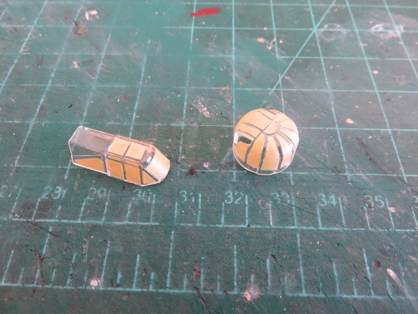
Now that I am finished my Wellington, I can forge ahead, guilt free, with my Defiant. It didn't take too long to finish up the Defiant's interior. The last remaining item was the instrument panel: This panel looks like it will be more visible compared with the Hurricane build I did earlier. Some thought could be given to getting an after market PE instrument panel, but I opted to keep things out of the box. Yahu models makes sone nice PE instrument panels for a variety of aircraft, if anyone is interested. It didn't take too long and things began to look a little more airworthy. There is a fairing on the upper fuselage just behind the turret, the kit offers the builder a choice of having this fairing raised or lowered. On the prototype, this fairing was operated pneumatically, and raised and lowered automatically as the turret was rotated. A similar moveable fairing was located between the turret and the canopy. I've decided to model both these fairings in the raised position, as it does give the aircraft a slightly more streamlined appearance. With the fairings lowered, things look a little disjointed, and realistically, they would not be lowered for any great length of time, unless the turret was paused in a position that required them to be down. Following the main airplane assemble, it was time to turn my attention to the canopy and turret masking. The canopy was fairly straightforward was more surfaces are flat and square. The turret offered a good reason to build this kit only once! If I had to do it again, I would probably try to track down a masking set. Prior to painting, I have since sprayed the turret and canopy with some Glosscote to seal the tape. I did this with my Hurricane and had zero paint bleed, or, at least, no coloured paint bleed as the Glosscote left no marks as far as I can tell! Painting is coming up quickly, although being all black, it should be nice and simple. No issues with wayward camouflage bands this time! Andy

- 36 replies
-
- 10
-
-
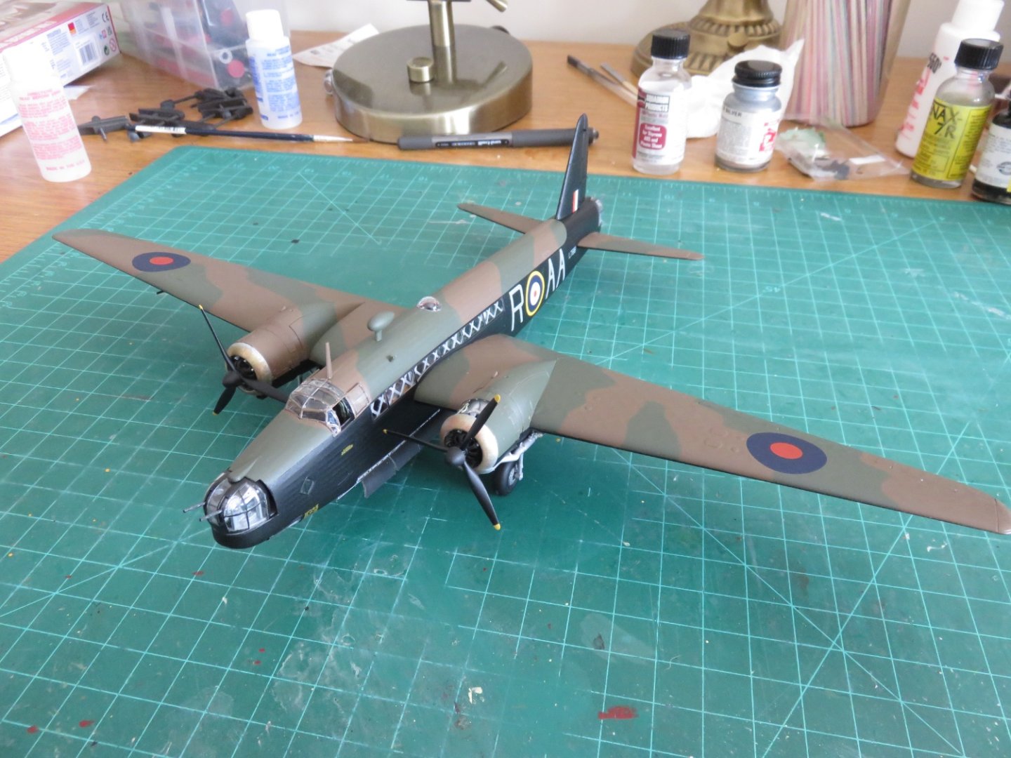
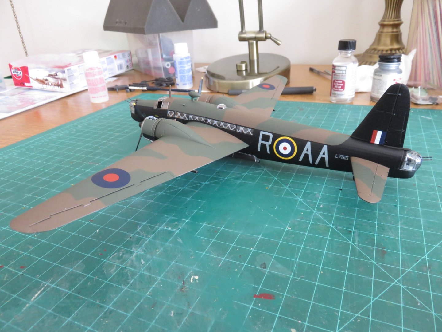
Let me first start off by once again offering my gratitude to all those who've been following my build and all those who left such nice comments and likes. Thank you all so very much! Well, for all intents and purposes, I think it's safe to say this build is done. Not 100% finished, as one day I will plan a small diorama around this model and there are a few details that will remain in storage until that point, but all other construction is finished! Hooray! After a final shot of Dulcote, the masks have all been removed to reveal a bunch of more or less clear windows (whew!). The sacrificial canopy was also removed and for the first time in a few months all the cockpit detail was once again visible. A large part of the interior remains just visible through the over-wing windows, so my efforts are not entirely lost. Rather than getting too long winded, I'll just post a bunch of photos for you all to enjoy! I am please how most things turned out, Airfix has produced a nice model, that can built out of the box and will achieve a very satisfactory result. The PE and resin upgrades were not without their challenges, but I think the results were worth it. Apparently Airfix will be re-releasing the Mk Ia/c later this year with new markings, so the kit should be readily available on the market again soon, although for Merlin fans, the Mk II is still in plentiful supply. For anyone interested in doing a bomber, but lacking the space to do a Lanc, this is a great option. Hopefully I'll see you all over at my Defiant build! Andy


- 174 replies
-
- 13
-
-

-
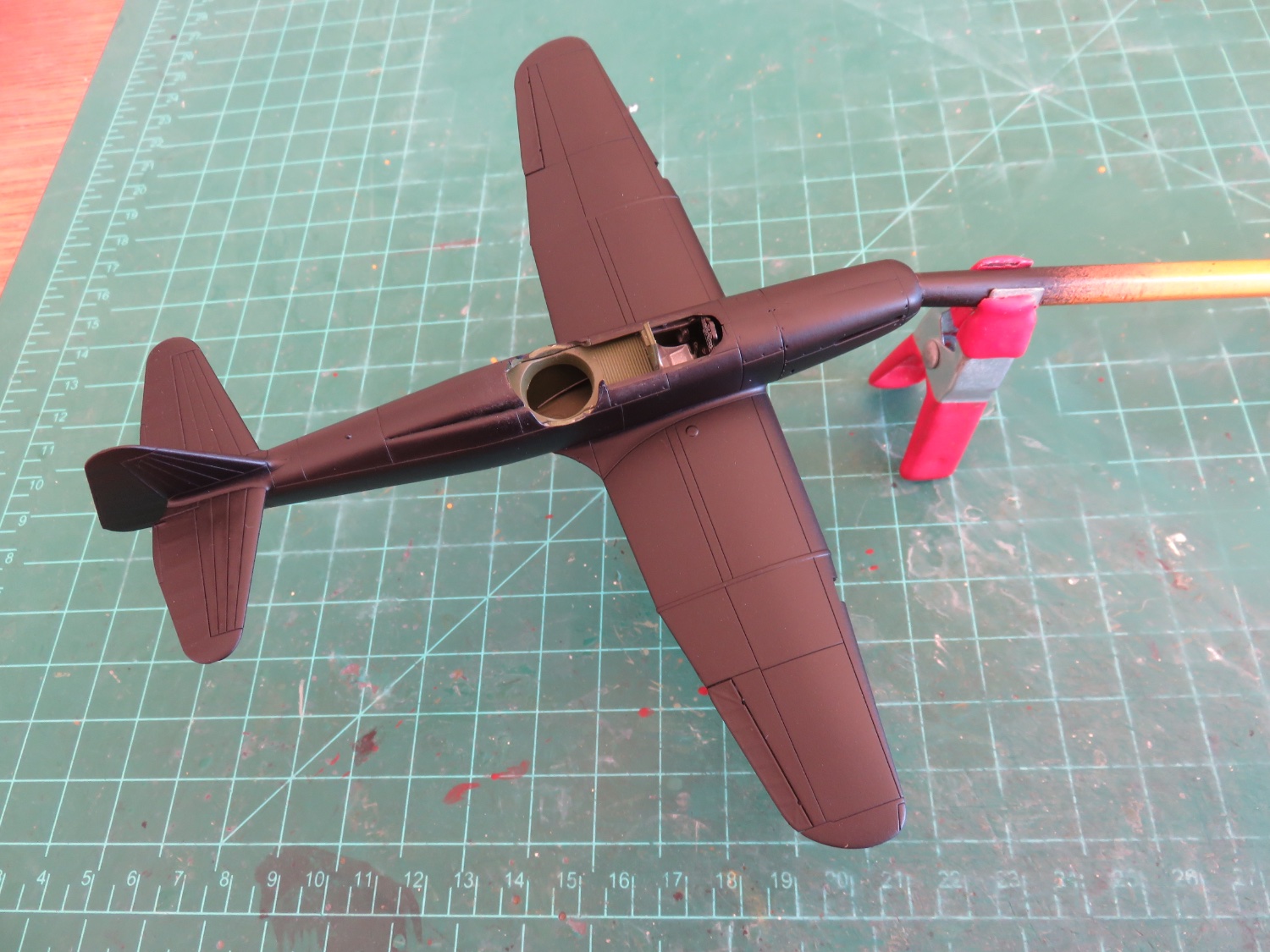
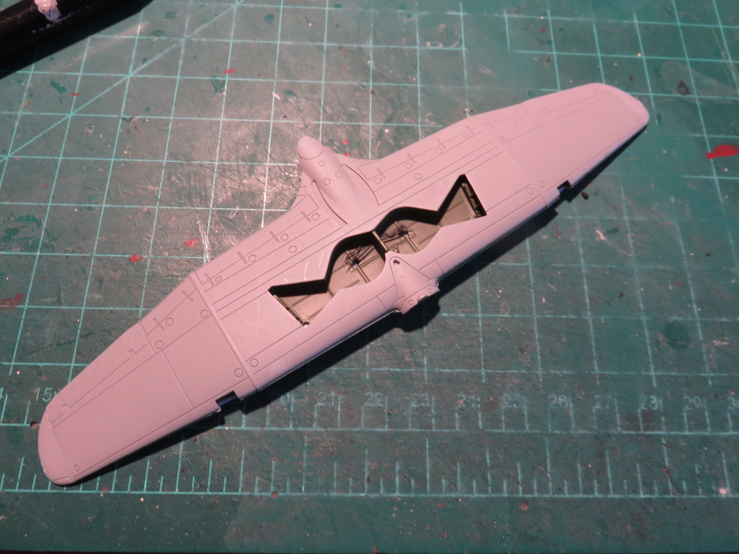
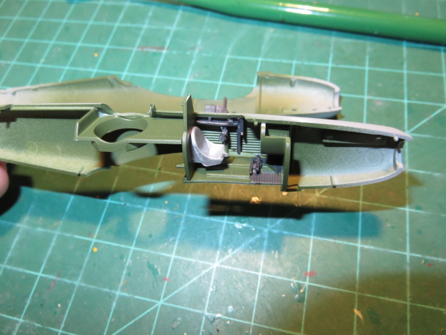
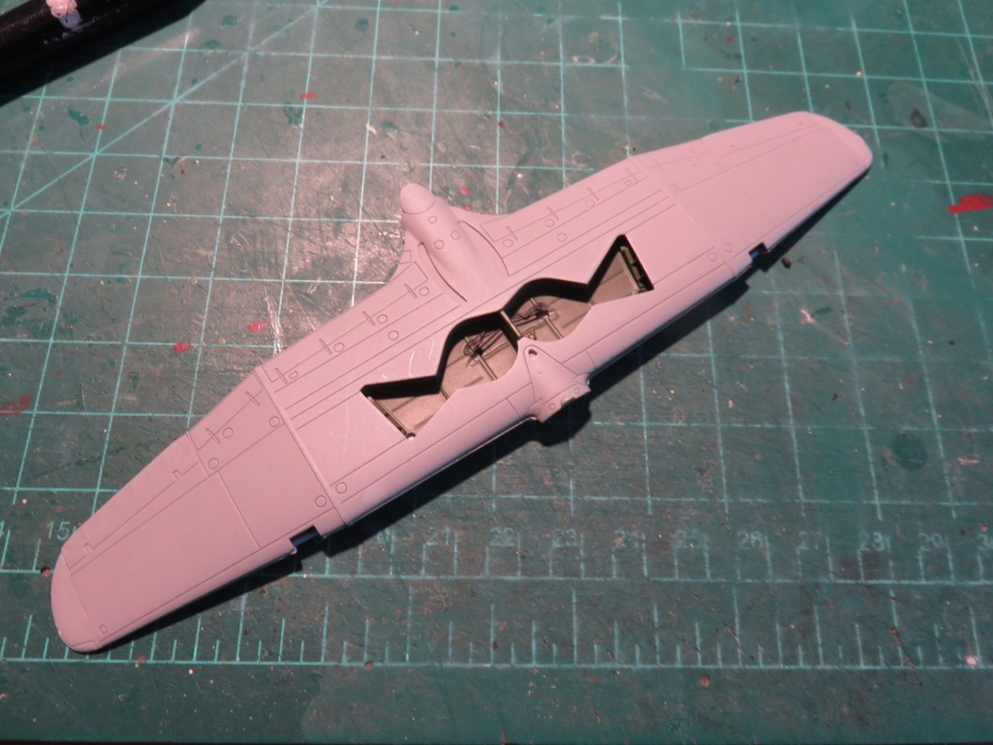
Thanks everyone who's joined in on this build (and those just passing through)! In between waiting for paint a glue to dry on my Wellington build, I have been picking away at the odd pre-assembly job on this build as well. My Wellington needs to sit for a bit to make sure everything is cured before I add the final shot of Dulcote, so I decided today would be a good day to start some assembly on my Defiant. This will only be a brief interlude as I've told myself I must finish my Wellington before I really get stuck in on this one. Like pretty much every Airfix model, assembly begins in the cockpit. There's a fait bit going on with this one, as it is a two seater, although to be fair, at this point the only thing going in at the rear is the turret support ring. The rudder pedals and control stick are particularly small, even for this scale. They're about half the size of the ones in my Hurricane. The control stick mounts in an odd location at the front of the seat (if you shake it more than twice, you're playing with it!🤪). I still need to add the instrument panel, but right now I'm waiting for the instrument decal to dry. Once that's set, the panel will be installed and the fuselage can be closed up. Jumping ahead a step, I've prepared this wing, so it will be ready to go on once the fuselage is assembled: Diverging from the instructions slightly, I've painted the insides of the landing gear bay the same colour green as the cockpit, and I've picked out some of the cabling/wires in gunmetal colour. The instructions say to paint everything black, but as I said in the intro, I feel that some of these details may get lost in an otherwise monochromatic paint scheme if they were all the same colour. I will be doing something similar with the details inside the turret, eventually. So far the model has gone together reasonably well, the only real issue I had was extracting the control stick from the sprue. Despite my best efforts the ring/handle at the top got a little a lot mangled. I was able to save it with a quick application of glue before the various bits wandered off into the ether, so no harm done. For anyone else attempting this kit, do beware of this particular part, it's booby trapped! Andy
- 36 replies
-
- 13
-
-
Thanks OC and Andrew, glad to have your kind feedback. If anyone else were to build this model, I would recommend this one upgrade kit over all the others, in terms of how much the appearance is improved (after that, I would suggest the engine upgrade!). Steady picking away, and the last doors have now been installed! First a quick in progress shot after getting the fourth run of doors installed earlier: Followed by a couple of shots of all the doors installed: Once the CA has had a chance to fully cure, the doors will be gently coaxed to their final open position, and the runs streamlined somewhat. Afterwards, a quick touch up of silver paint on the areas where there was some paint loss due to the Eduard origami, and a shot of Dulcote to seal everything. The end is now rapidly drawing into sight as only a few remaining fragile bits are left to install, as well as swapping out the cockpit canopy. This was the last major assembly hurdle to be cleared. Andy

- 174 replies
-
- 14
-
-
-
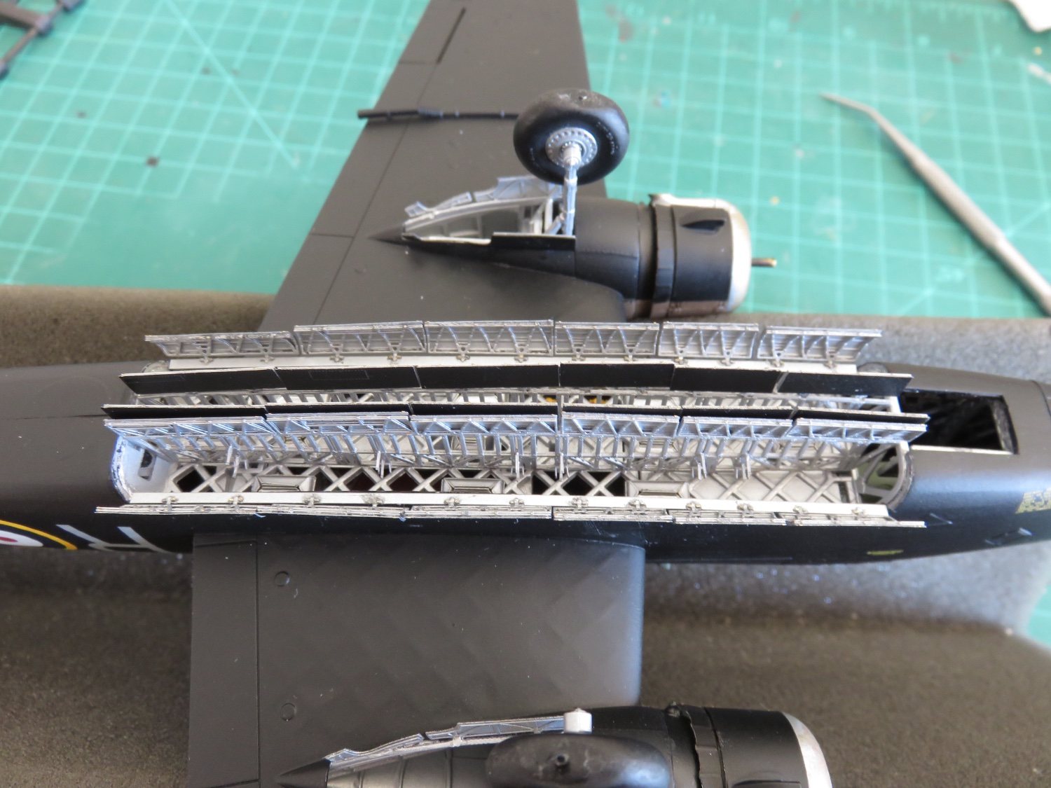
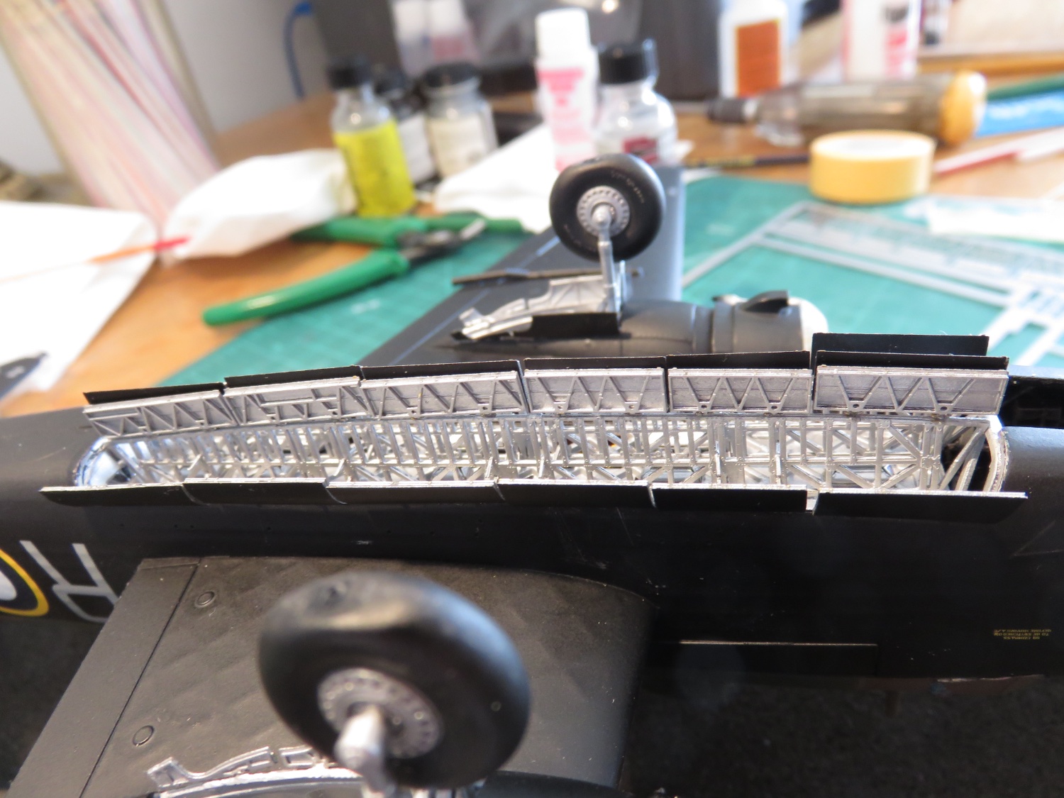
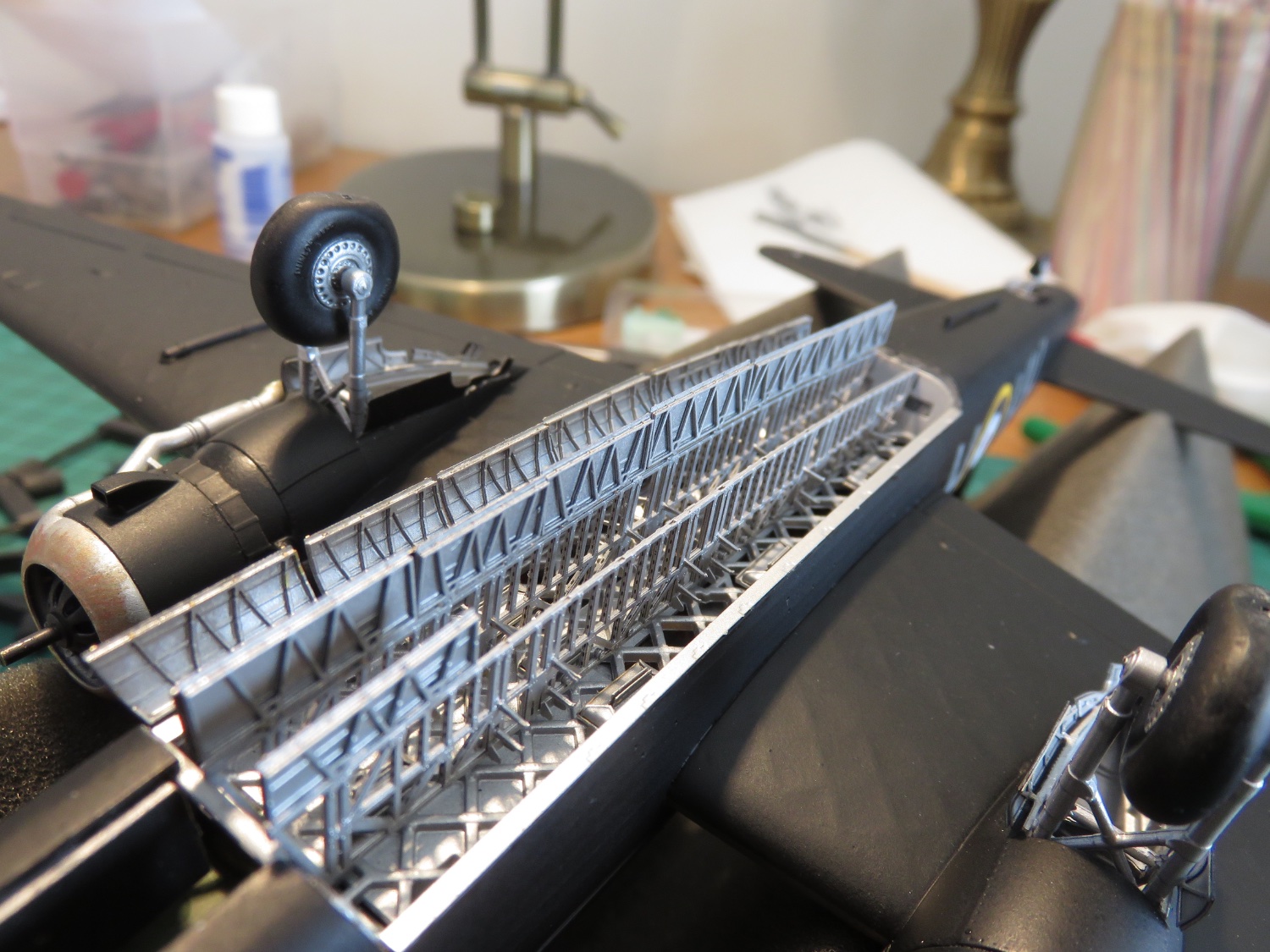
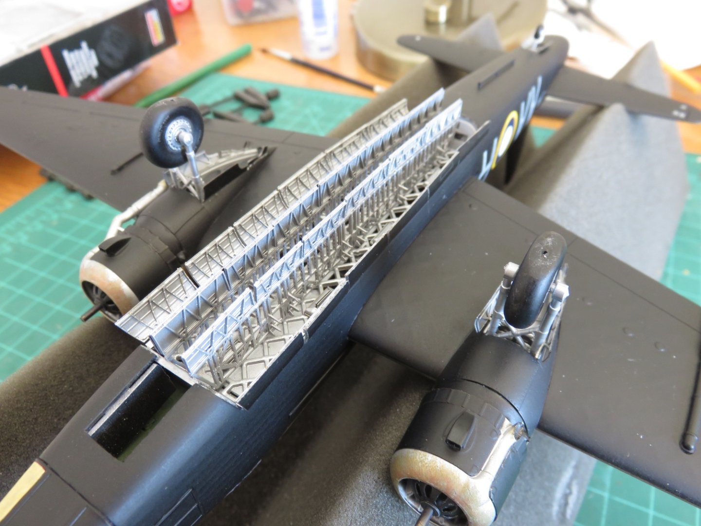
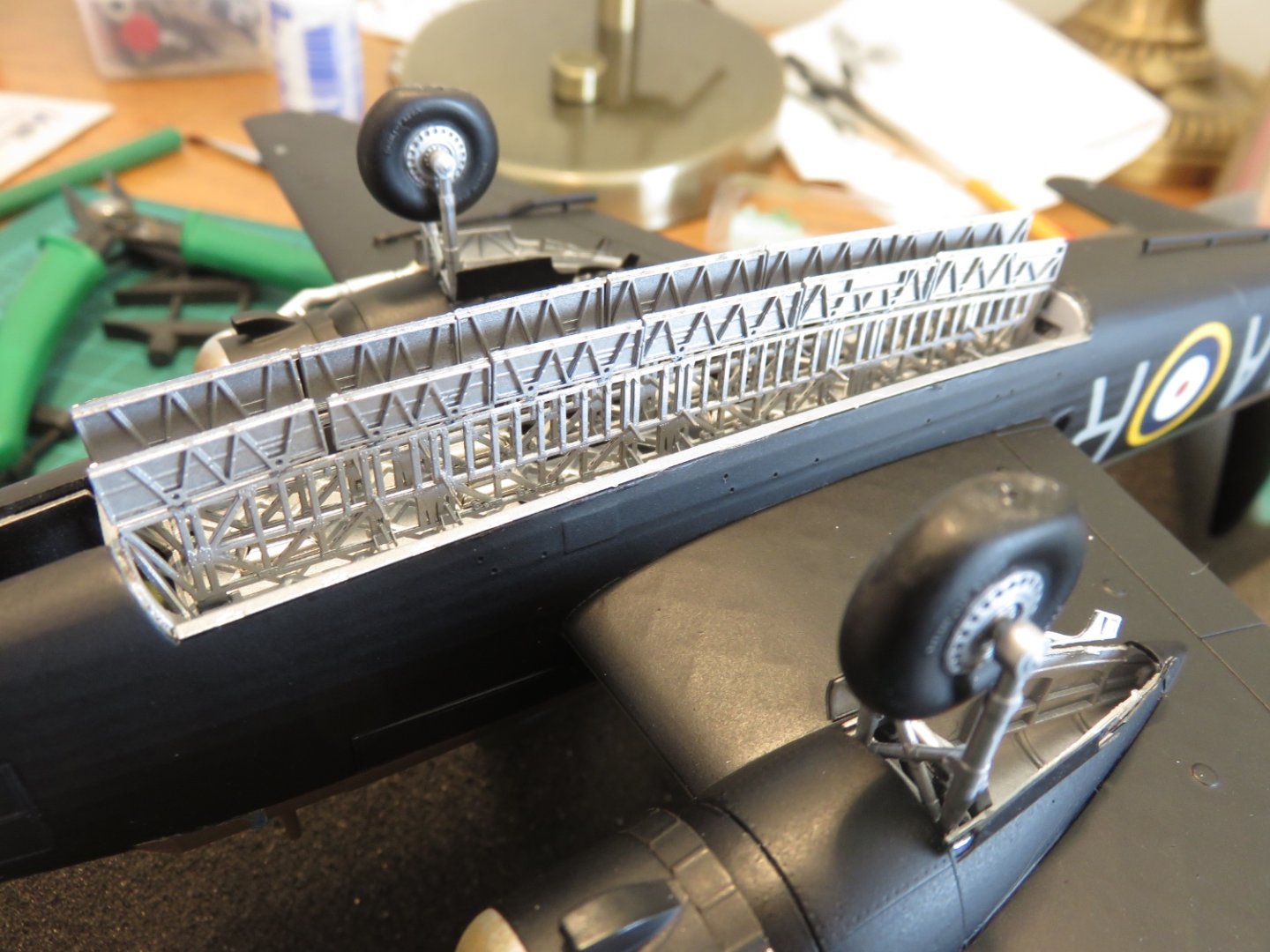
A little progress to report: 19 of 30 doors have now been installed. It's a tedious process, and a little finicky, but it's progress. Along the way, I discovered an error in the Eduard instructions; two runs of doors had their numbers reversed, luckily this error makes itself apparent very quickly, and it was able to be remedied with no further consequences. For anyone else who's building this model, the numbers for the inboard doors for the outboard bomb bay need to be swapped (ie what the instructions show as the left side doors are actually for the right side, and vice versa). Also the instructions say these inner doors would have a slight curve, but based on prototype photos, these doors should not be. Anyway, some pictures of the progress so far: The most tedious bit was doing the double row of doors on the closest (in the above photo) bomb beam. Thankfully from here on out, the doors are only in single rows, things should go much quicker. All the doors will need to be adjusted slightly to their final positions, so the runs don't look so disjointed, but that will wait until after all the doors are installed. Andy


-
I was feeling a little guilty for having neglected this build (thanks @AJohnson 🤪!), I figured I had better get on with it and get my Wellington finished, or at least on the path to being finished. Then I can get after my Defiant build with a clean(er) conscience! 😁 The bomb bay doors are going to be a bit of a slow process. There are 30, in total, almost identical looking doors that have to be bent, glued so they don't unfold like an accordion, and installed in the correct sequence, in the correct location. I'm just in the process of gluing up the first door. Oh, how much fun this is going to be! But it must be done. Previously I prepainted the doors on the PE fret, as masking and painting after installation would only have resulted in tears. As it is, there will be some slight touch up needed around the fold points, but not a wholesale re-paint. Proof of life, this build is still active! Andy

- 174 replies
-
- 10
-
-
-
I think most of the victories against the 109s were more due to cases of mistaken identity more than anything. From a distance the Defiant does vaguely resemble a Hurricane, so when the 109s would bounce a flight of Defiants from the rear, they found out the hard way that that’s where all the guns were! Otherwise the best defensive tactic for a flight of Defiants, when engaged by enemy fighters, was to form a descending Lufbery circle. This tactic was developed and proved by 264 Squadron, however when other squadrons came online with Defiants, some ignored this advice and incurred heavy losses. Andy
-
This would be a new tooling from Airfix, released in 2014 (ok, so not new, new, but new). As stated in the video, both the Defiant and Roc were perfect examples of what happens when concepts and realities work at cross purposes. Sounds like a good idea on paper, not so much when the laws of physics and aerodynamics decide to get involved. Andy
-
It seems nutty, but it was based on a sound principle. This video about the Blackburn Roc (I would argue a good candidate for the absolute worst fighter of WW2), explains the concept of zero deflection shooting: Andy
-
Nah, I’m not allowed to lift anything because of my shoulder, you’re safe. 😁 I’m thoroughly ill-equipped to debate camouflage patterns of the RAF, but now you’ve given me something of a basic understanding, I’ll pay closer attention in the future. Of course, trust the British to be bureaucratic about their camo schemes! Thanks to you and everyone else for your kind compliments! I’m glad my efforts have met your expectations. Andy
- 92 replies
-
- 10
-
-
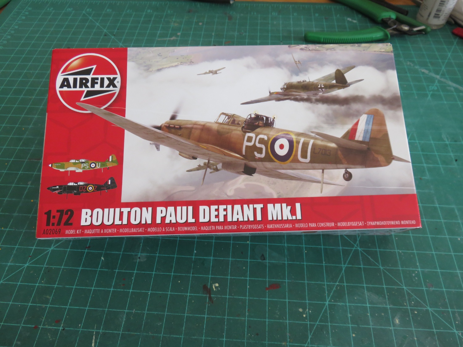
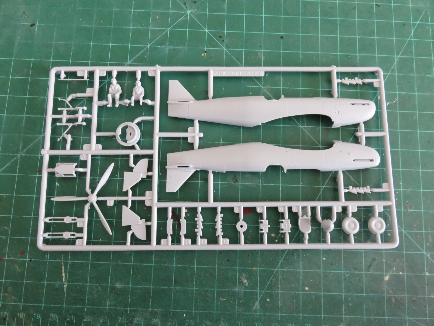
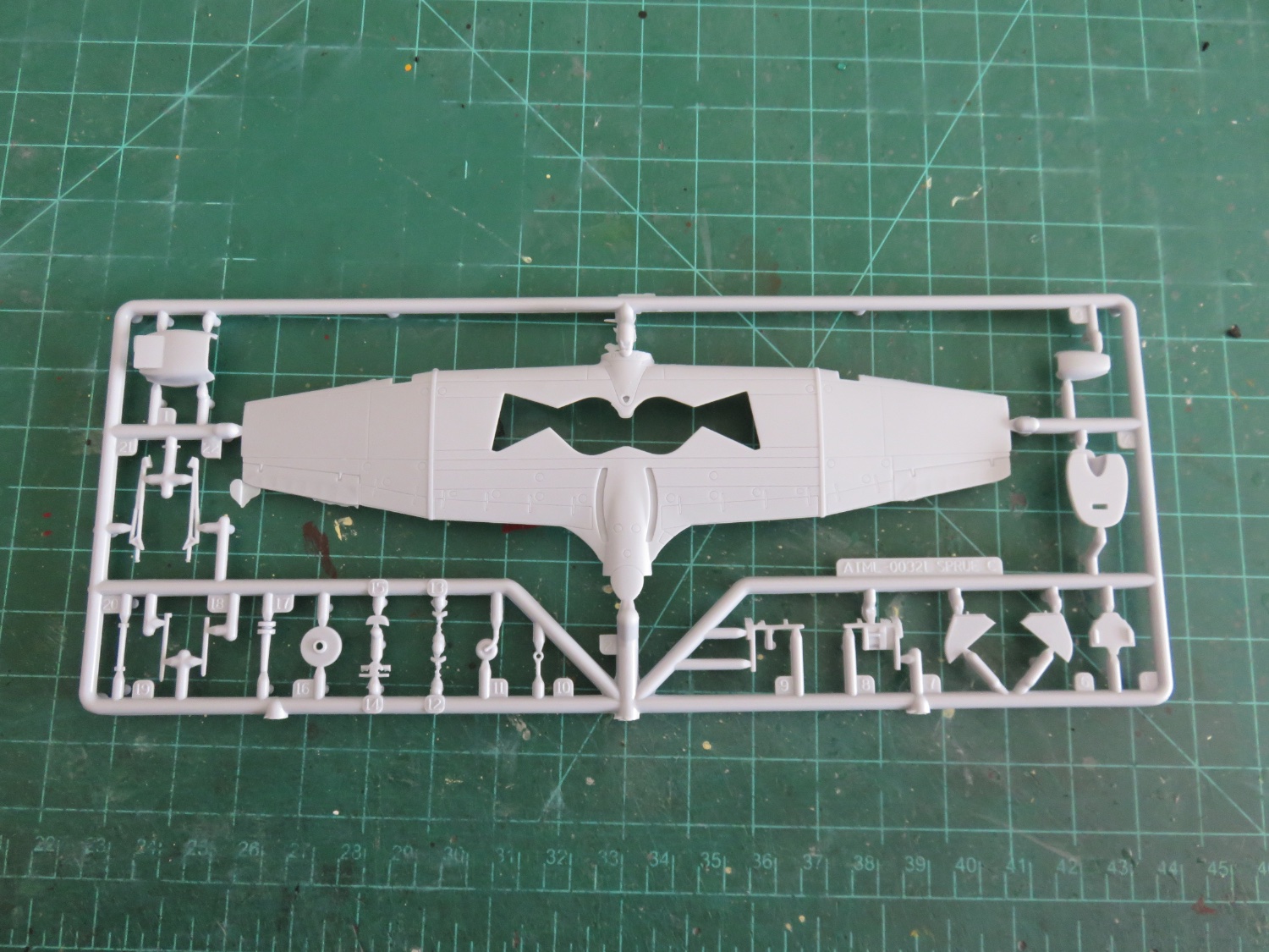
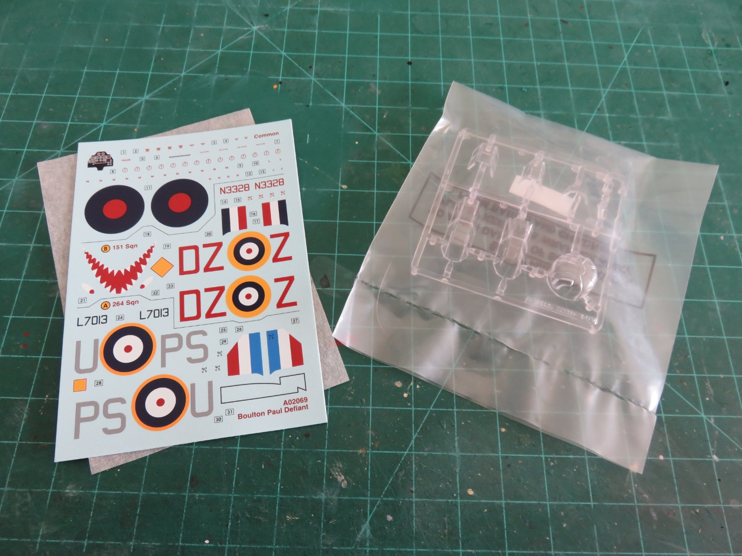
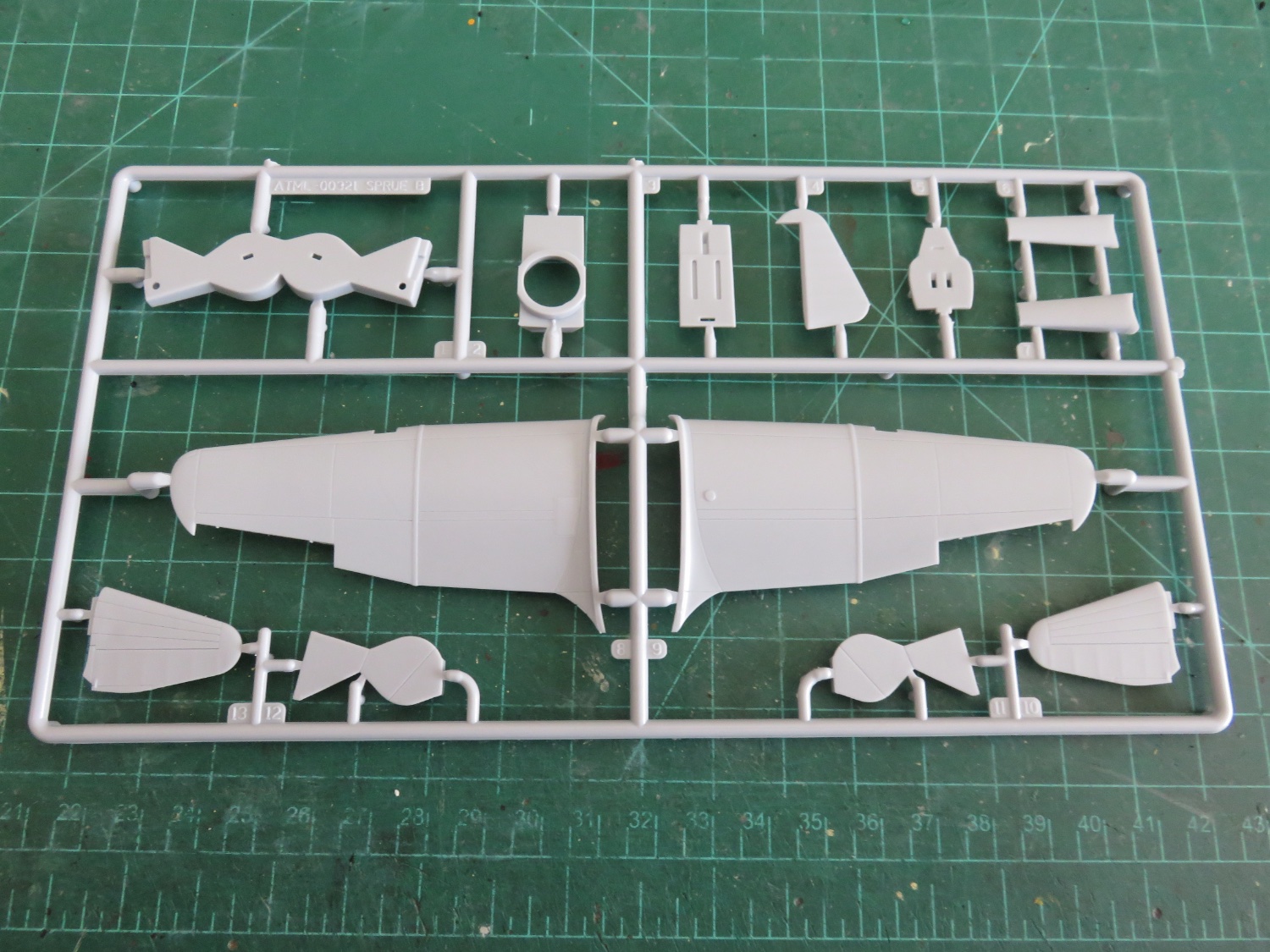
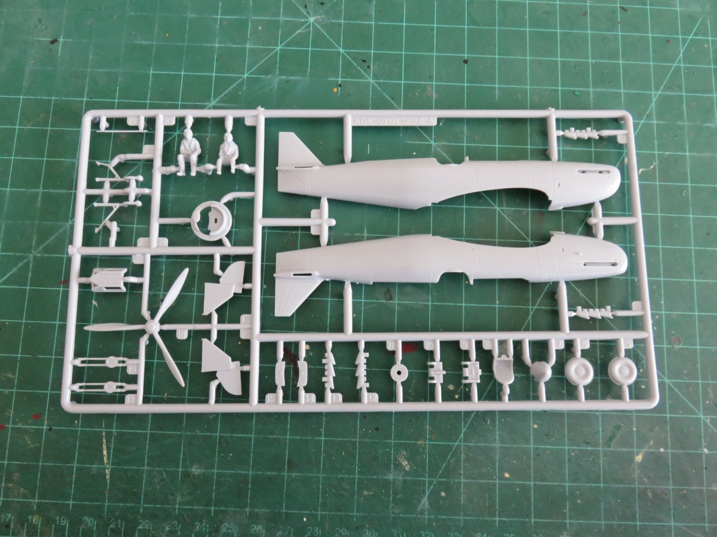
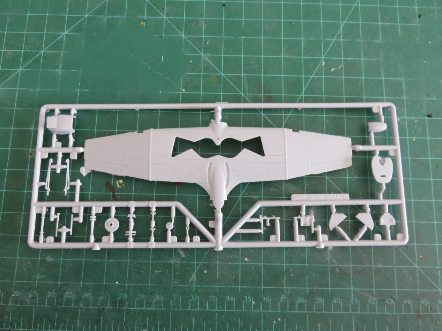
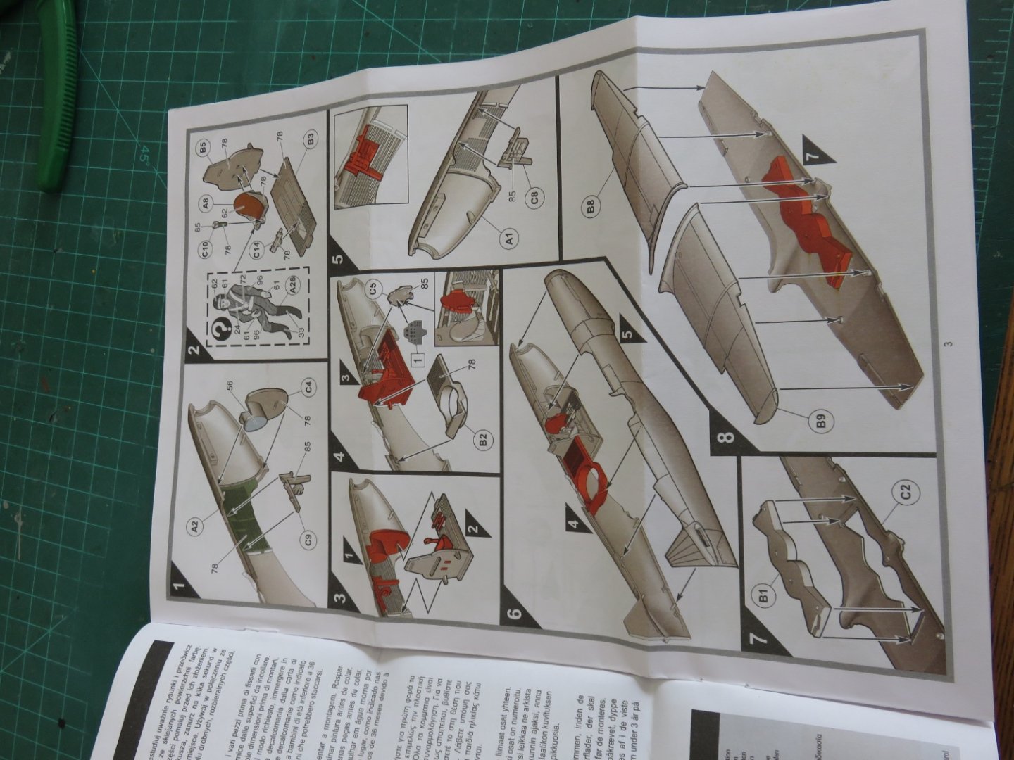
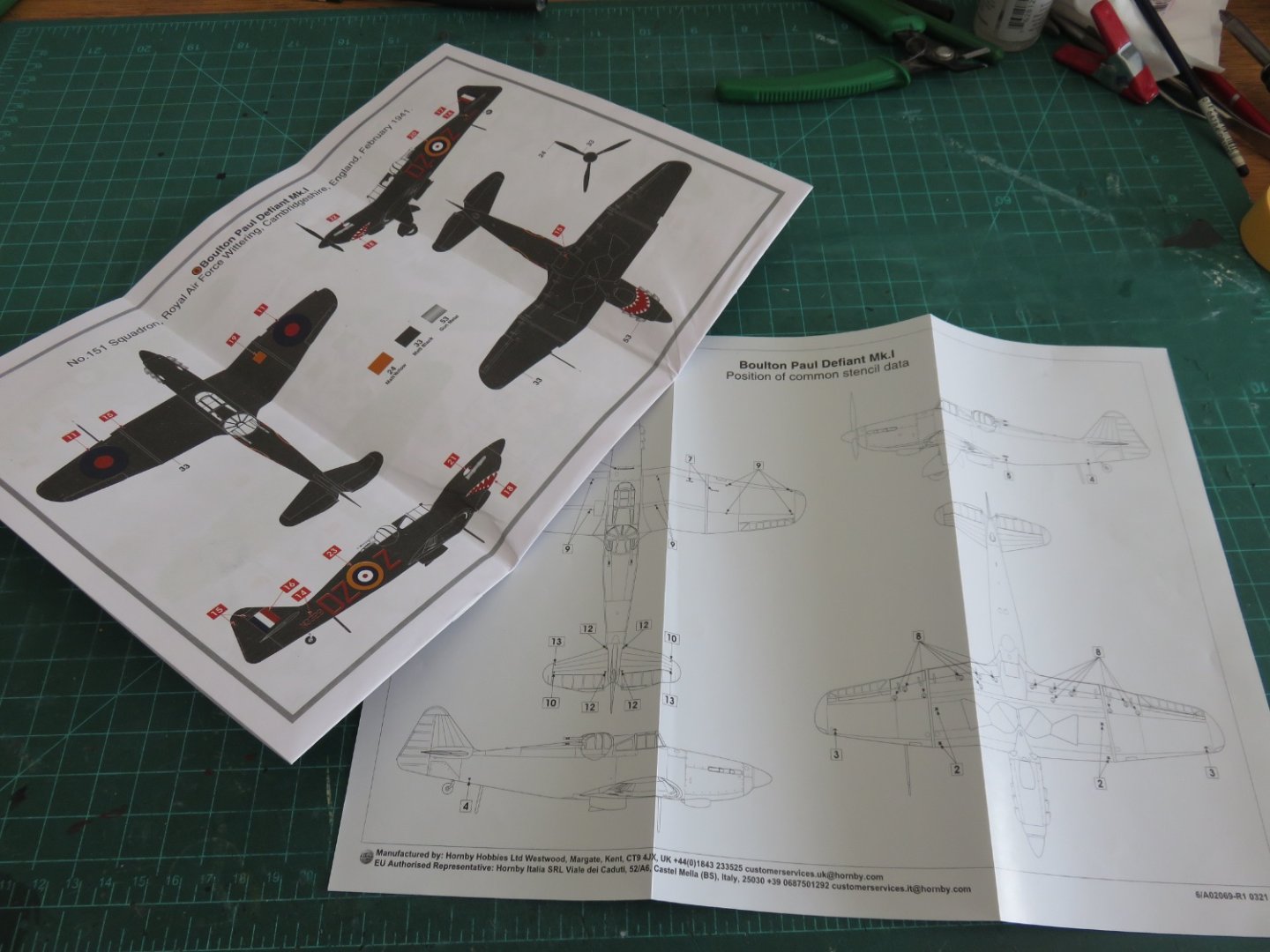
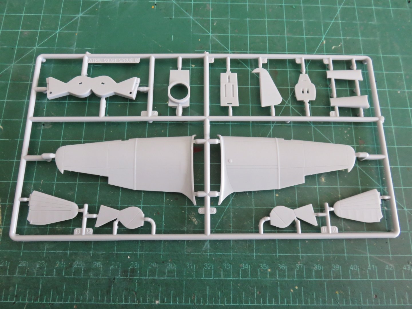
Since my shoulder is still under strict doctor's orders to not do any lifting, I will happily keep myself busy with another small kit from Airfix, and maybe another later on. The Boulton-Paul Defiant would definitely be categorized as one of the more bizarre concepts offered to the RAF in the late interwar period. The basic premise was that a fast interceptor could infiltrate itself into a stream of enemy bombers, and with little maneuvering required, decimate the enemy craft with it's "heavily" armed turret. Due to it's slower top speed, and inability to dog-fight effectively, it has become a somewhat maligned aircraft (unfairly if you ask me). When deployed with well trained crew (especially well trained in tactics), in the role for which it was intended, with Spitfires or Hurricanes providing adequate cover, the Defiant was a somewhat effective fighter, and it proved to be an even more effective night fighter until the introduction of faster and better armed Beaufighters and Mosquitoes into the role. For a better basic history of the airplane, check out here. The Airfix kit comes in its usual red box with some nice cover art. The contents consist of three grey sprues of parts, along with one clear sprue for the canopy and turret. All in all the parts are cleanly moulded, but there is a bit more flash in the sprue with the lower wing section. It doesn't look too bad, and should pose too much of a problem getting the parts cleaned up prior to painting/assembly. There are multiple options for the cockpit canopy to choose from. An interesting feature, the Defiant had two fairings, one forward and one aft of the turret that could extend or retract pneumatically as the turret rotated. Airfix allows you to choose how these fairings are displayed. The decals are once again from Cartograf and two options are available, either a day fighter from 264 squadron (the first Defiant equipped squadron) or a night fighter from 151 squadron. The instruction booklet is printed in full colour and features full painting guides as well as a separate sheet showing the locations of the stencils (of which there are a lot), common to each paint scheme. I'm planning to paint this one as the night fighter version, a bit of a break from the "sand and spinach" of my previous builds. I will take some liberties from the specified paint scheme, to highlight some of the details, such as the turret interior and the landing gear bays, if only to avoid them getting lost in an otherwise sea of black. Plus, the airplane features a pretty nifty shark mouth (and eyes), which should make it stand out nicely. Hopefully this kit will be as fun to build as my recently completed Hawker Hurricane. Andy


- 36 replies
-
- 12
-
-
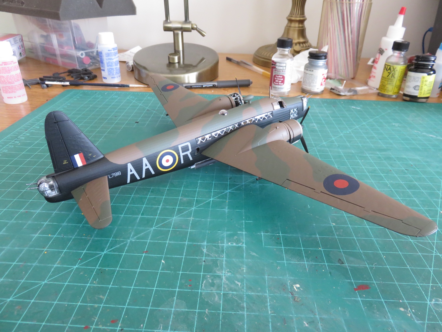
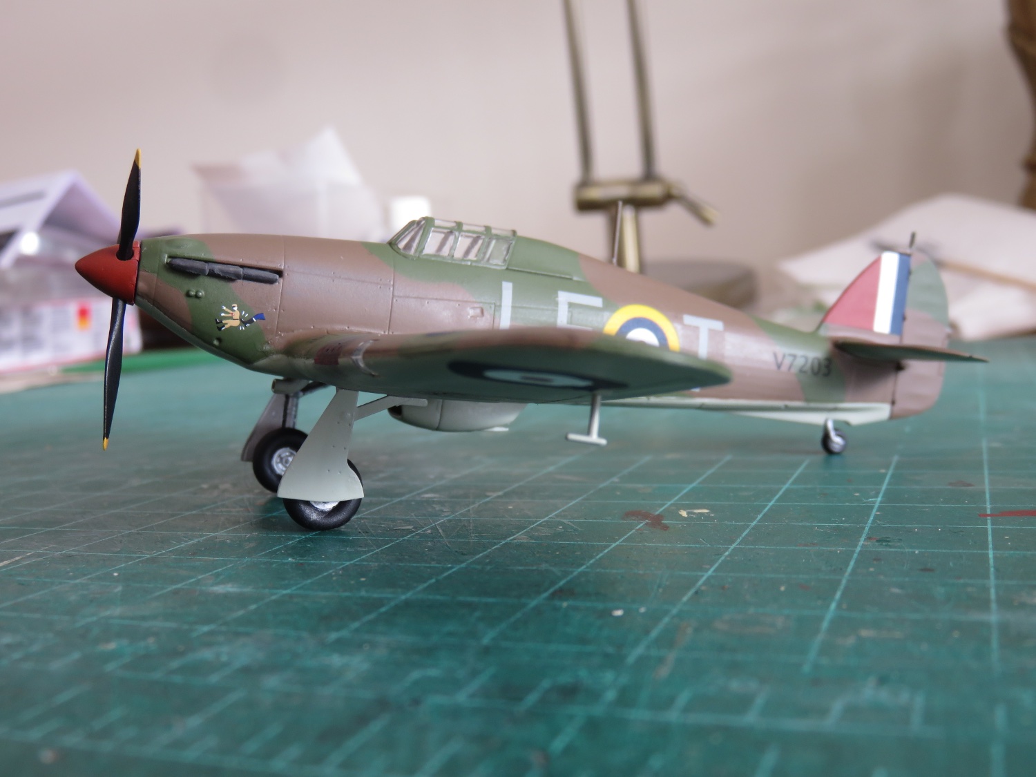
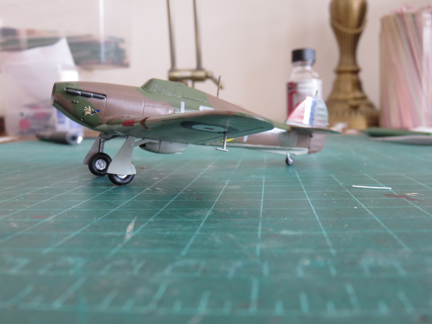
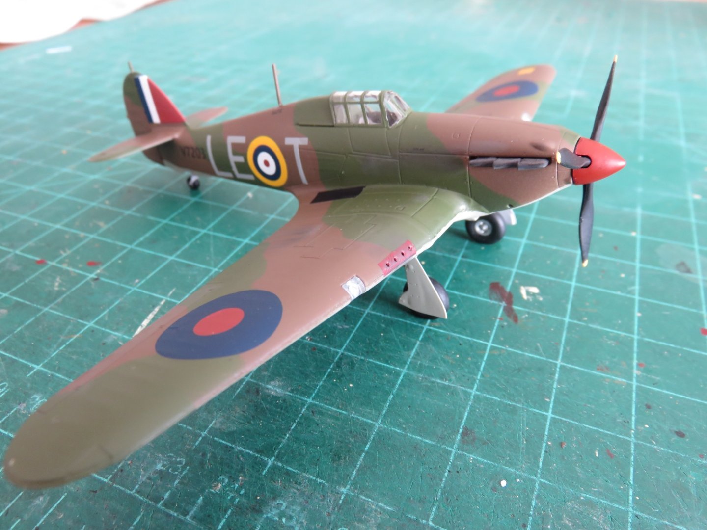
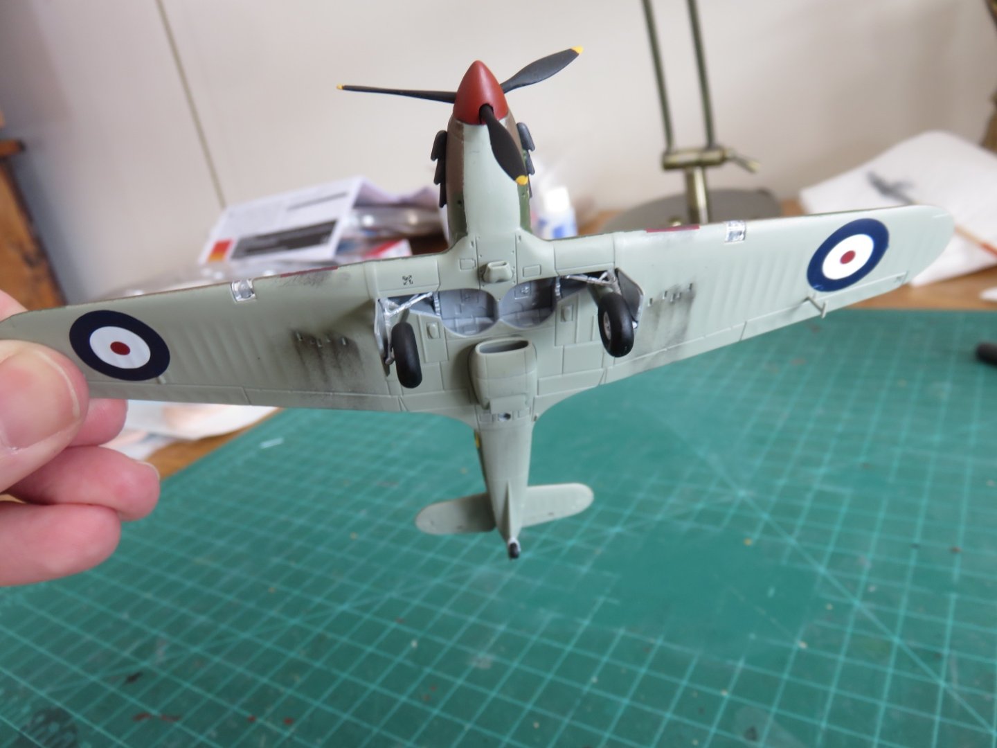
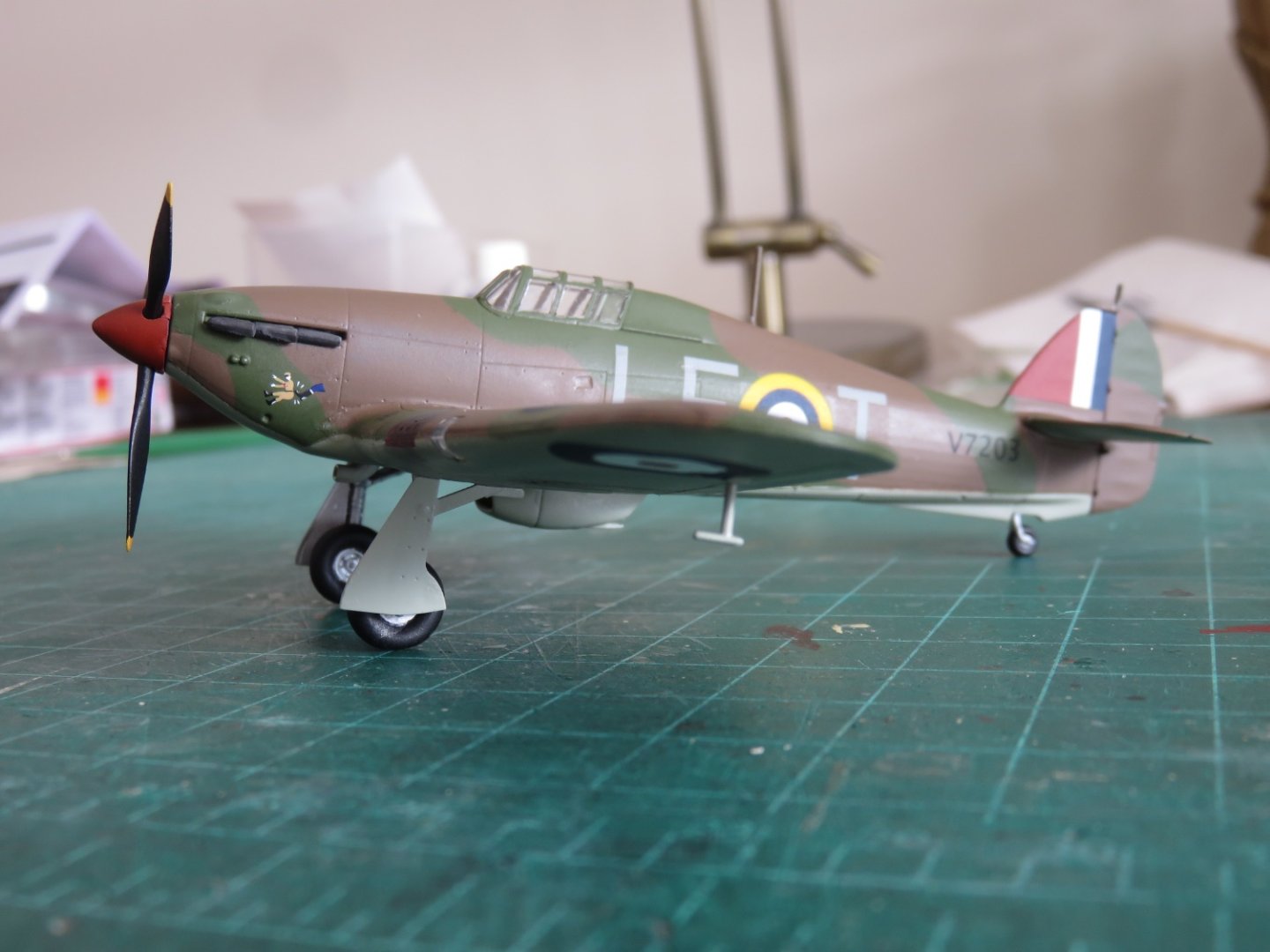
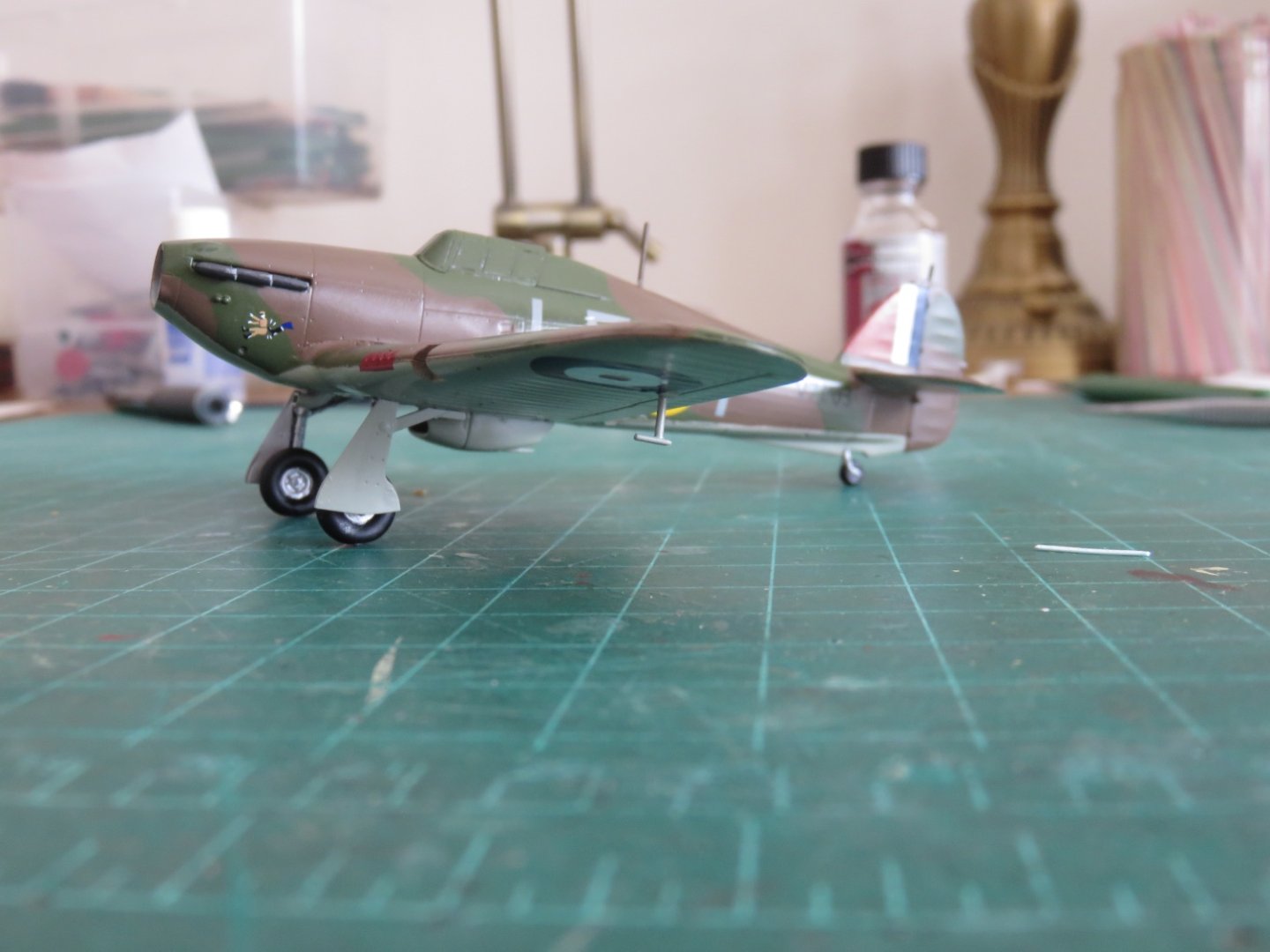
Thank you all for the kind remarks and likes! Well, I think it's time to call this one done... hooray! I wanted to keep the weathering light, just enough to suggest use. It was accomplished using Pan Pastel grime and soot colours and a soft applicator sponge in key areas. Oh, yeah, although the prototype appears to have a black spinner, I decided to paint mine red, mostly because I like the effect. I think I did pretty well by the prototype! (Although my camouflage bands run in the opposite direction) Overall this has been an enjoyable build, and I would highly recommend the kit. Airfix has done a great job, and at a really affordable price point ($17.50 CAD), it's hard to say no. There's not too many crazy small parts, so even at 1/72 it should be manageable for most. I have my next build already lined up, so stay tuned for more fun. Andy
- 92 replies
-
- 16
-
-
-
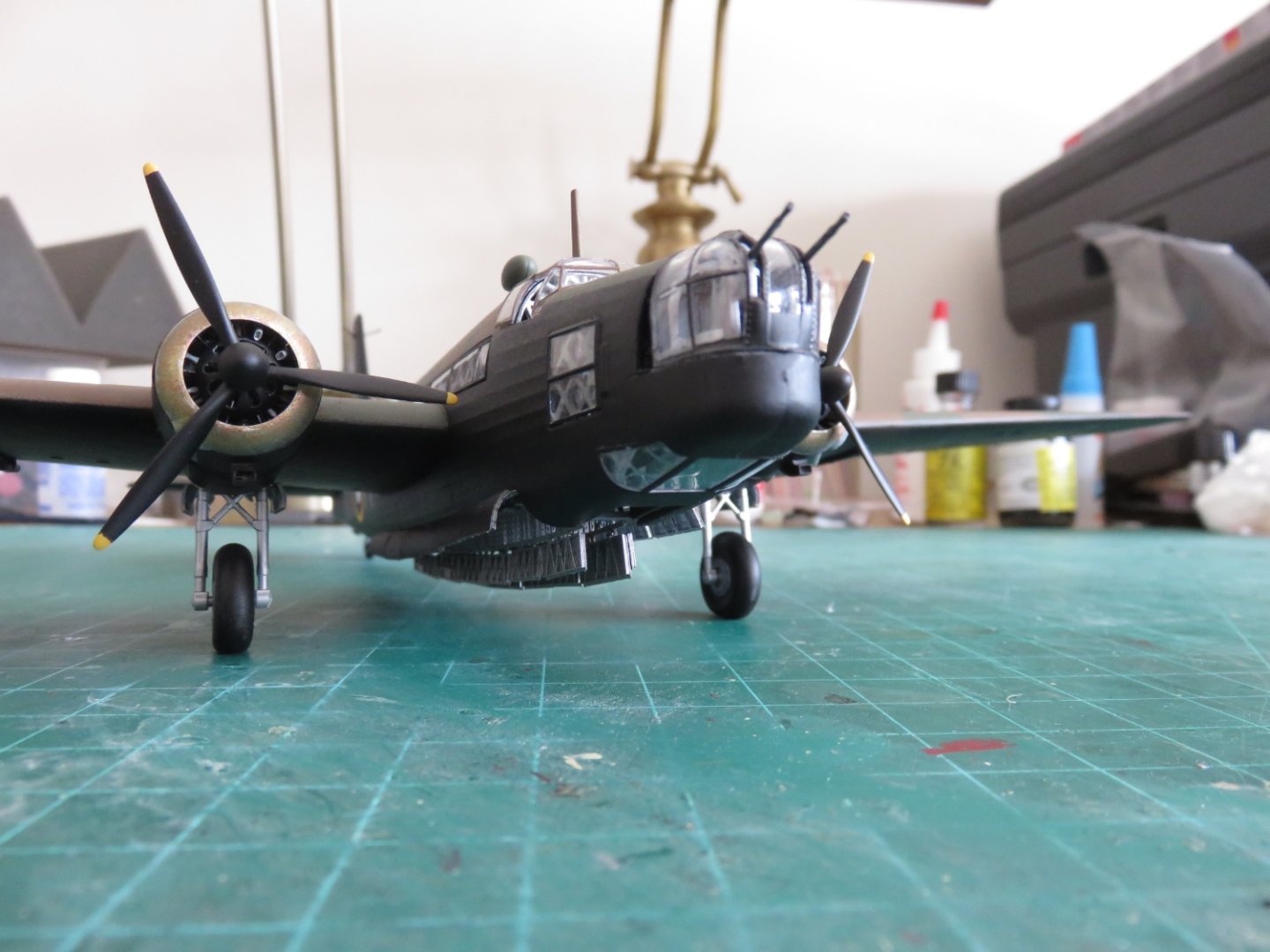
Thanks again, everyone, for your kind comments, likes and continued support! A small update this morning, as I inch towards the approaching finish line (although, not too much inching left). The landing gear is now attached! It's nice to see her standing on her own three (?) feet! A few of the other more fragile appurtenances have also been (re)attached. The arial masts are repaired and standing tall, as well as the pitot tube. I've left off the prop and spinner for now, as the open nose, along with my sanded pencil (HB lead) makes a great holder for painting. There only remains to add a coat of Dulcote to seal everything, then add the landing lights and finally the prop. I will probably add a little pastel weathering in some key areas, to make it look like she's seen some service, but not to the point of looking horribly beat up! Andy
- 92 replies
-
- 11
-
-
Thanks Alan! A quick google, and you would be correct. P3576 GN A, flown by James Nicolson: https://en.m.wikipedia.org/wiki/James_Brindley_Nicolson Andy
-
Thanks EG! Hang in there, hopefully everything goes well! When I was still sailing, I’d be forced away from the workbench for just about the same timeframe. I know how badly my fingers were itching to get back building something, you must be feeling the same! Thanks Mark and OC! Andy
-
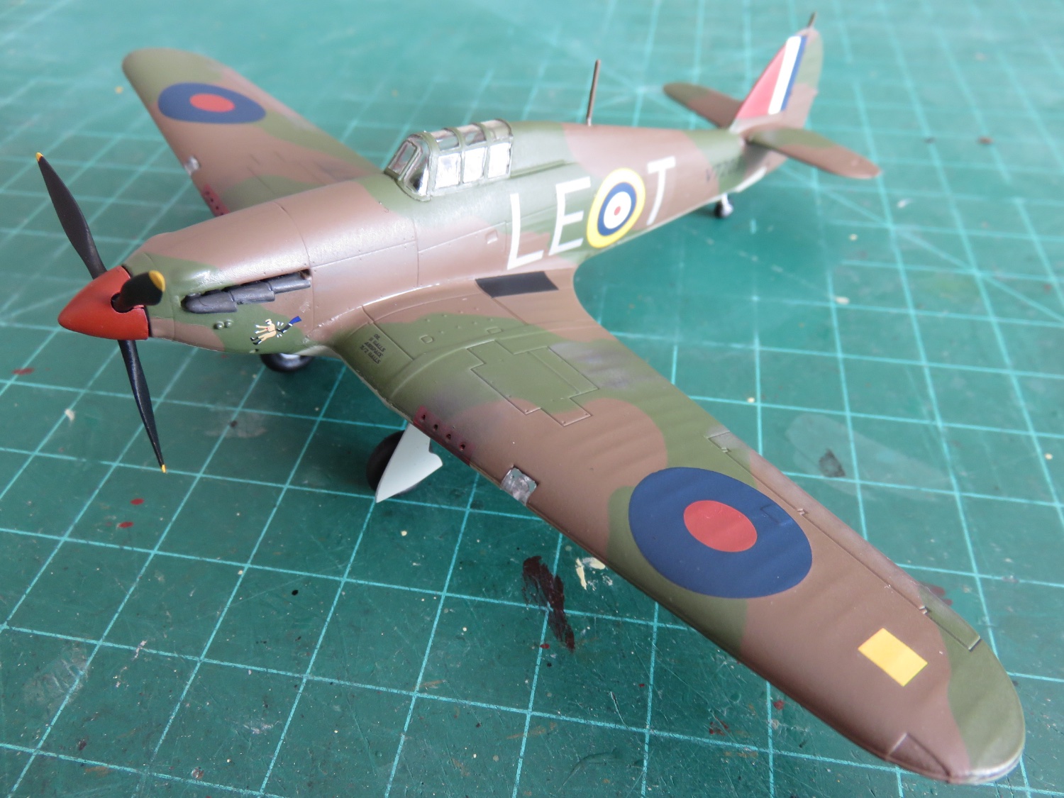
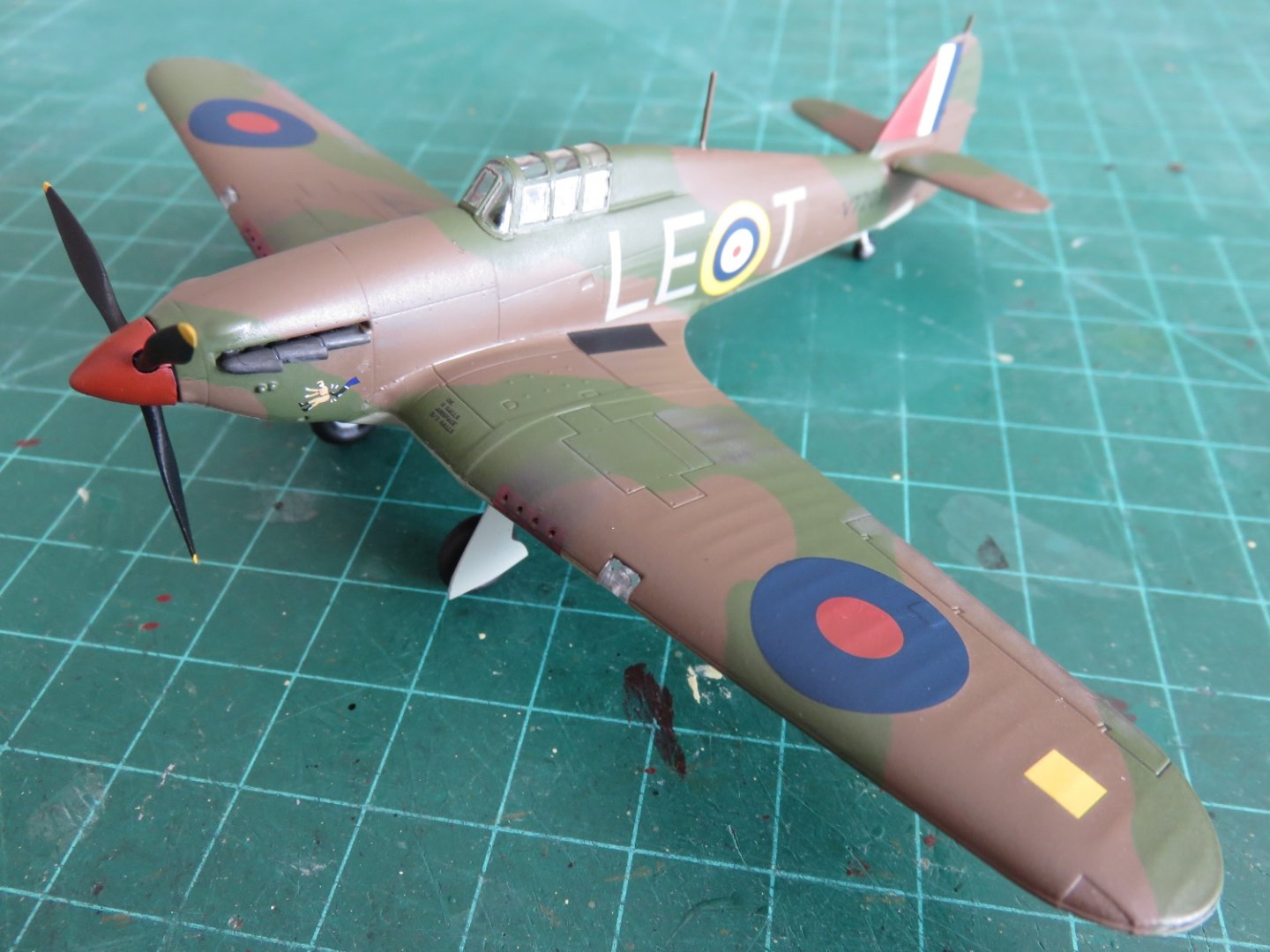
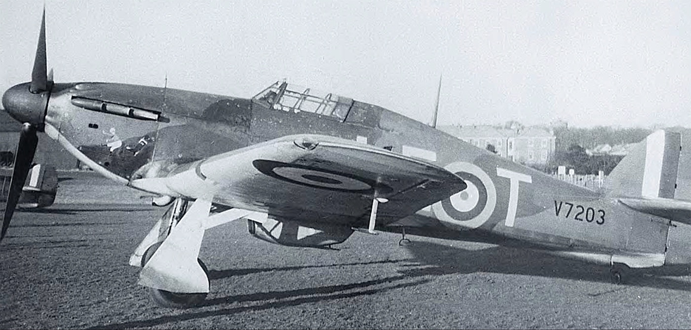
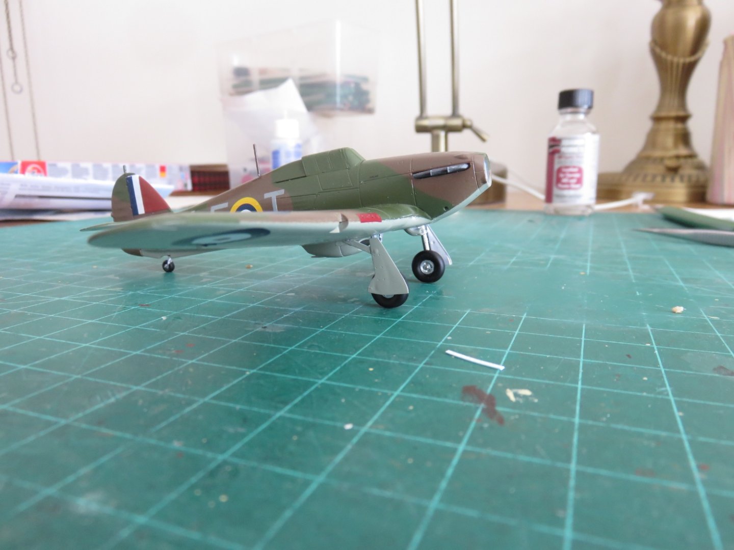
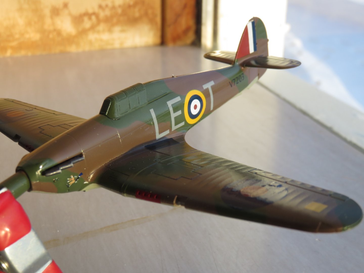
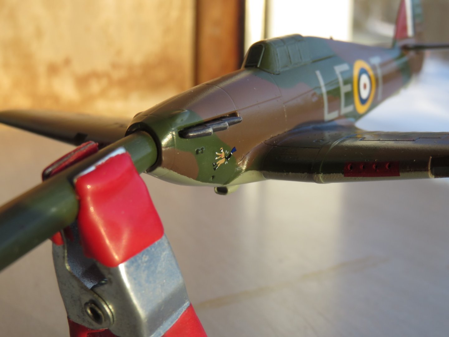
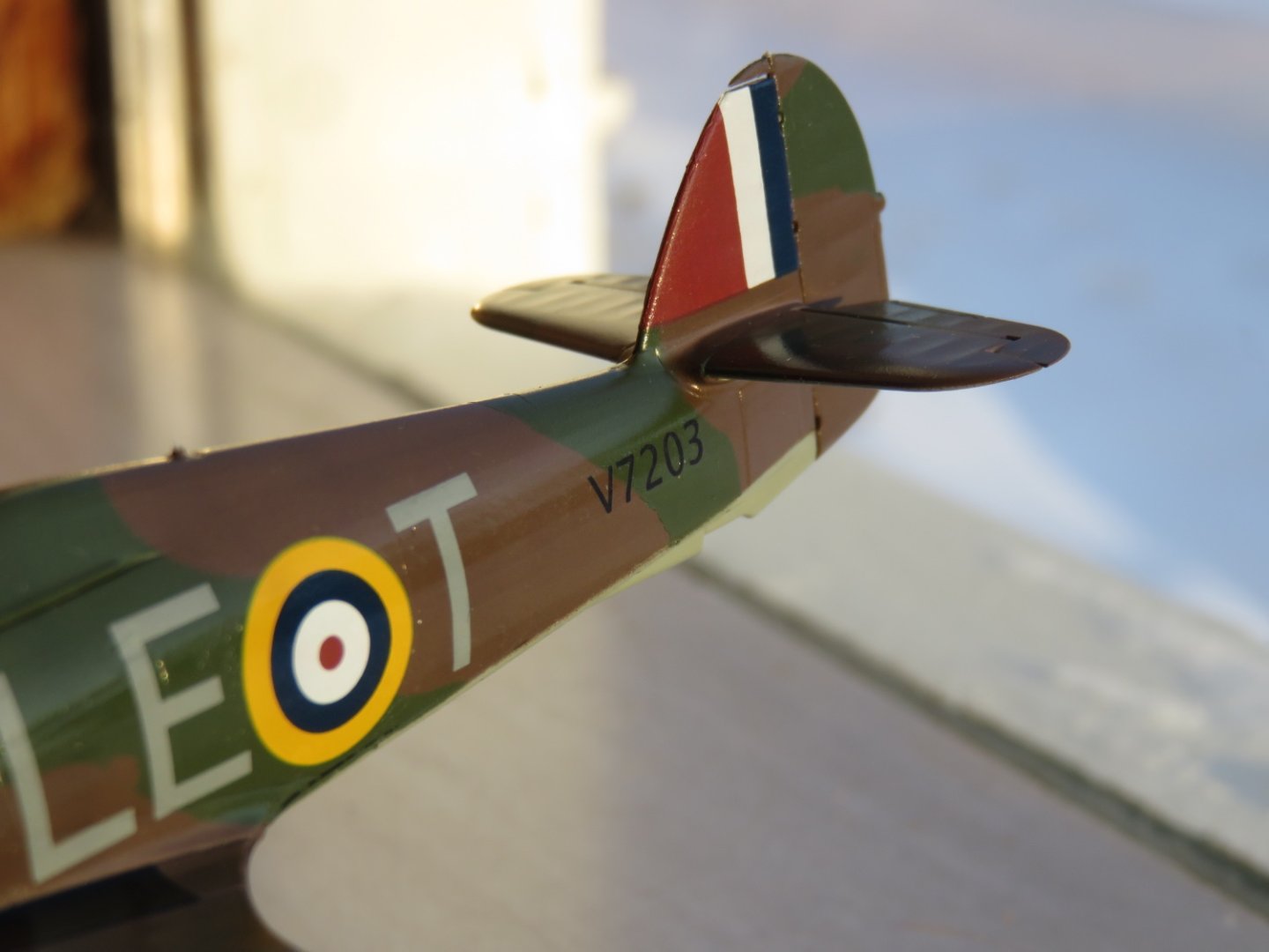
Hi everyone! It's update time (finally!)! Last Monday's appointment went well, all the staples came out, and I was ordered to begin moving my arm again, so the sling came off too. Things are slowly improving and my range of motion is steadily being restored. I'm still restricted from lifting things for another few weeks, but I'm happy to be able to do most things for myself again. I've also returned to the workbench and have some progress to share with you as well! I've spent the last few days lettering up my Hurricane. As I referenced before, based on photographic evidence, V7203 (LE T) was one of a small number of late delivered fabric winged Hurricanes, so it seems appropriate to use the marking supplied in the Xtradecal set for this aircraft. I was still able to use the technical stencils from the Airfix supplied decal sheet, as these were not part of the Xtradecal set. Slightly differing from contemporary bombers, the squadron lettering is presented in the same order on both sides of the aircraft, LE T on both sides, where the bombers where more mirrored (on my Wellington one side was AA R and the other side R AA). Nicely included was the 242 (Canadian) Squadron nose art of good ol' Adolph getting the Boot! The registration number was not included in the decal set, I'm assuming at the time it was developed, it was not known. As I mentioned before, the discussion on Britmodeller showed that LE T bore the registration number V7203. I made this decal by playing around with fonts and type sizing in a word processing program, before printing on blank decal paper with my laser printer. Finally, the underside roundels came from the Airfix supplied sheet. I'm very pleased with how things have turned out, next steps include attaching the landing gear before sealing everything. Eagle eyed viewers may have noticed the missing antenna masts. They became inadvertently detached during the pause in construction, but they are in a safe location and will be reattached soon. It feels good to be back at the workbench, once again, thanks to everyone for all your kind words of support and encouragement. Andy

- 92 replies
-
- 13
-
-
Looks like a fun one, hope you don’t mind if I tag along! Andy
-
Thanks! Yep, I did plow snow, and I sure left an impression! So far so good in the recovery, I’m off the pain meds, except the odd topical, as all the muscles in my shoulder are taking turns twisting themselves into knots. Otherwise no major issues as far as I can tell. Counting the days until the stitches come out and I can lose the sling! Andy
- 92 replies
-
- 11
-
-
A little update today on my progress. I had surgery on Tuesday afternoon, finally, and things are now beginning to mend. It will still be a little while yet before I’m back at the workbench, but at least there’s now a better chance of me getting there. I have a follow up appointment on the 30th, hopefully by then the stitches come out and the sling can come off. One day at a time, but moving forward. Thanks again, everyone, for all the well wishes and words of support. This is absolutely a great community to belong to. @JKC27 I hope you share that Lanc project with us, as well as your Spit! You can’t tease us all like that! 😜 Andy
- 92 replies
-
- 13
-
-
Thanks! Yeah, the kit supplied wheels did have the flat spot too, although I really don’t think Airfix designed them to be free rolling, it’s just a happy coincidence that they could be. Andy
-
Nicely done Kevin! Congratulations on finishing! You should be proud of your work, it looks fantastic! What a great way to start off the new year! Andy
- 38 replies
-
- 4
-
-
- Lady Eleanor
- Vanguard Models
- (and 1 more)
-
This one: https://www.sunwardhobbies.ca/border-models-avro-lancaster-132-scale-with-full-interior-bf010/ ?? Have fun!
-
Thanks! Sounds like you’re having fun with that modelling club! Yeah they’ll lead you down some rabbit holes, but it’s all fun. Airfix kits are generally pretty good, with some caveats. The more recent releases are cleaner, better, moulds, and require somewhat less fussing. If you see something interesting (regardless of manufacturer) you can check on Scalemates to see when the kit was tooled, preview the build instructions, and see what’s available in the way of aftermarket parts. Andy