tmj
-
Posts
778 -
Joined
-
Last visited
Content Type
Profiles
Forums
Gallery
Events
Everything posted by tmj
-
 Homemade Chisels?
 -
Nice carving detail!
-
I'd hit the like button, but I don't really like this this sort of thing at all. "Fingers are crossed!"
- 732 replies
-
- 4
-

-

-
- Lula
- sternwheeler
- (and 1 more)
-
Really nice-looking, clean, crisp model! Good job! So.... what's 'next'?
- 47 replies
-
- 3
-
-
-
- Annapolis Wherry
- Chesapeake Light Craft
- (and 1 more)
-
Gunboat Philadelphia 1776 by tmj
tmj replied to tmj's topic in - Build logs for subjects built 1751 - 1800
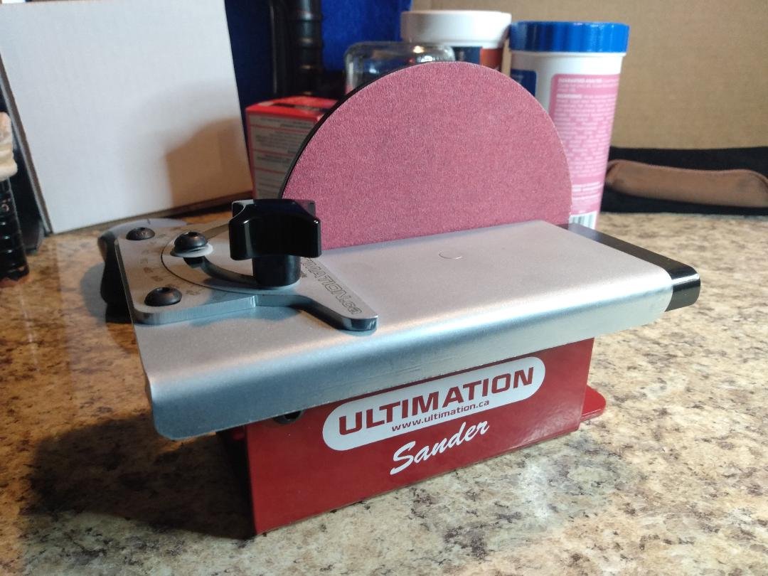
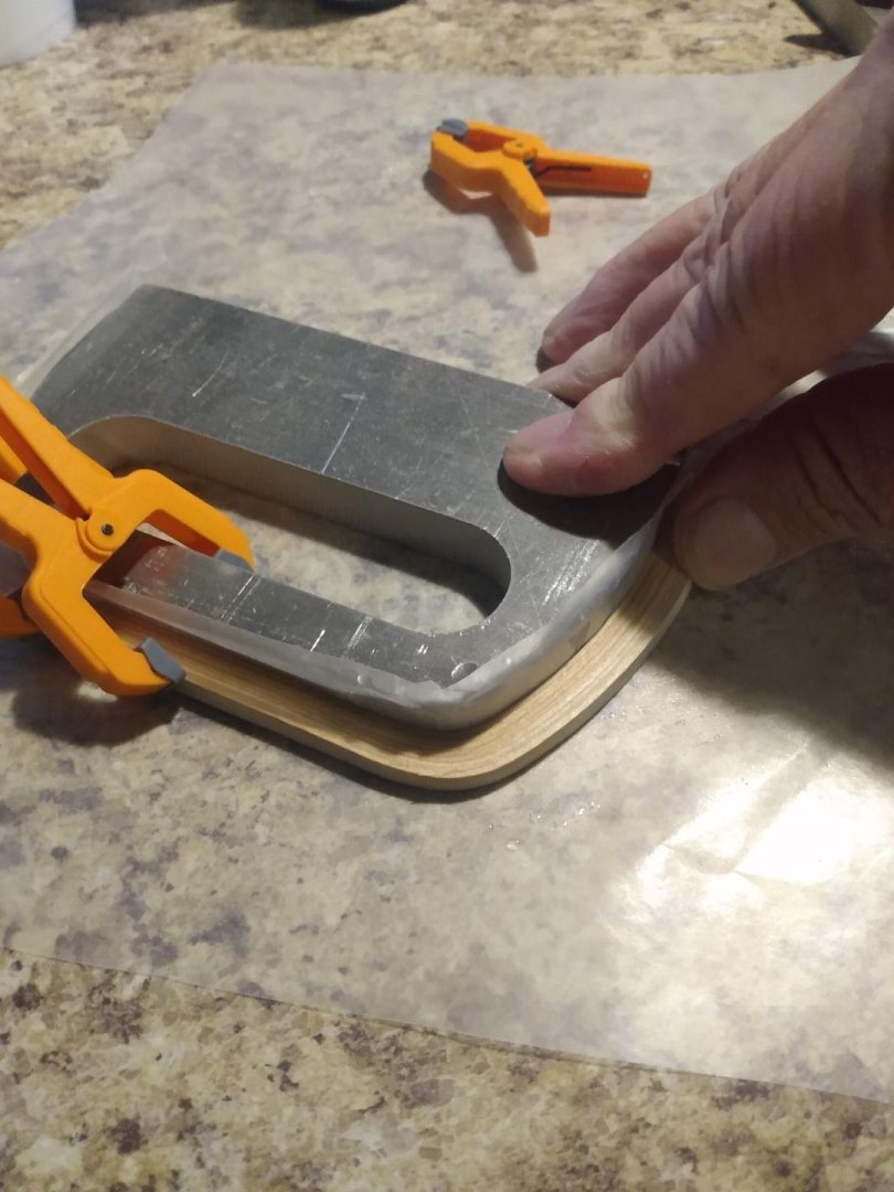
Progress has been slow due to the laser breaking and preventing me from cutting my finished frame sanding templates, but all is well now. I cut 4 templates yesterday. There will be 18 sets of frames to sand, so I cut 4 templates to prevent me from sanding away the edges of any one template and creating inaccurately shaped parts. I used stainless steel to make sure my templates don't rust should it take me a while to sand all of the frames. I'll attach the template to the laminated frames with either 2-sided tape, or rubber cement if the tape doesn't hold well enough. Here's one of the sanding templates. Here's a sanding template laid atop a laminated frame set. There's quite a lot of meat to lose, but that was necessary in order to produce the effect of longitudinal grain inside a hand hewn 'bent' timber. They are also taller than needed. As mentioned earlier, these laminated pieces will each make two frames once split in two. I'll rough cut with a bandsaw, then sand the frames to the template shape using my new Ultimate sander. No mess, no noise... I'll be able to comfortably sand frames while sitting at the island watching TV! There should be no noise coming from the Mrs. either! *Fingers Crossed*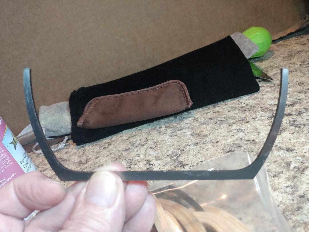
-
Gunboat Philadelphia 1776 by tmj
tmj replied to tmj's topic in - Build logs for subjects built 1751 - 1800
Nah, not right now. All the local flies disappeared from Dallas so Ribbit caught a Greyhound to Florida for the winter. -
Gunboat Philadelphia 1776 by tmj
tmj replied to tmj's topic in - Build logs for subjects built 1751 - 1800
Just in case anyone is interested, Olha Bachvarov is going to start a live group build of Model Shipways' kit of the Gunship Philadelphia beginning on Saturday 03 May 2025 via her YouTube channel. -
Gunboat Philadelphia 1776 by tmj
tmj replied to tmj's topic in - Build logs for subjects built 1751 - 1800
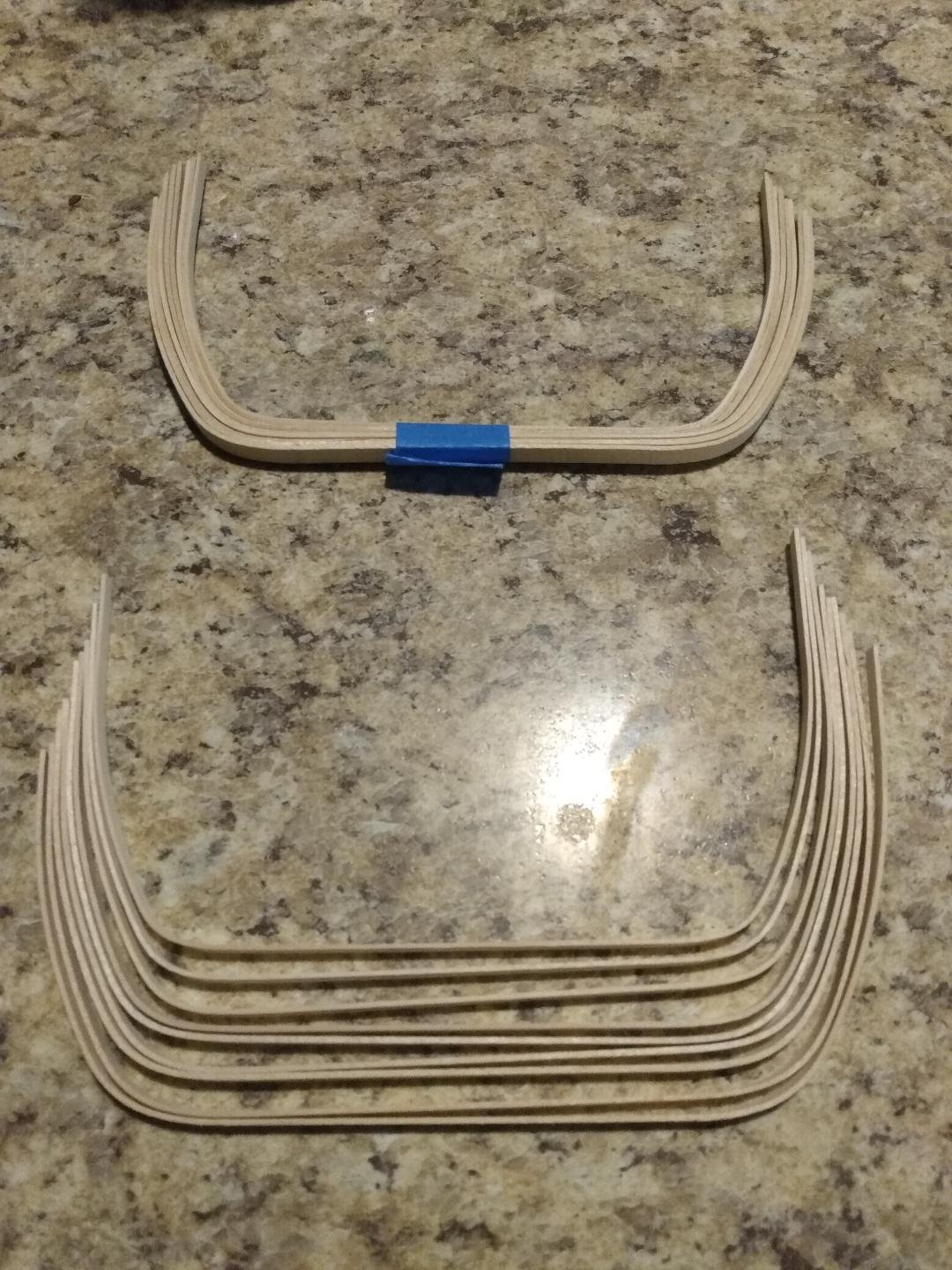
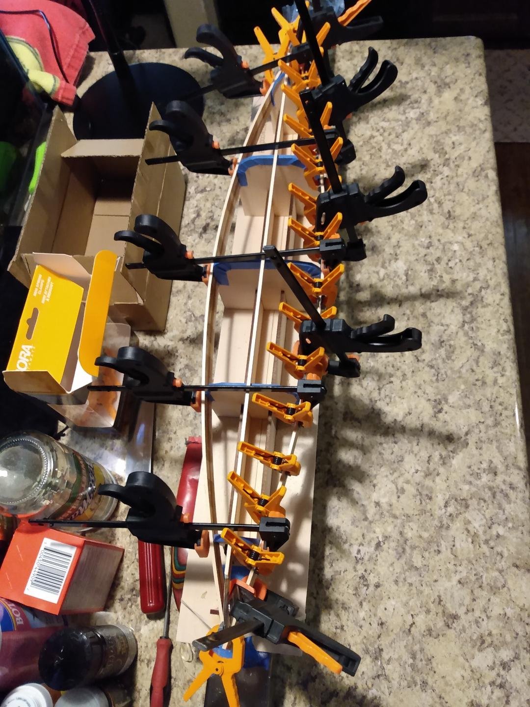
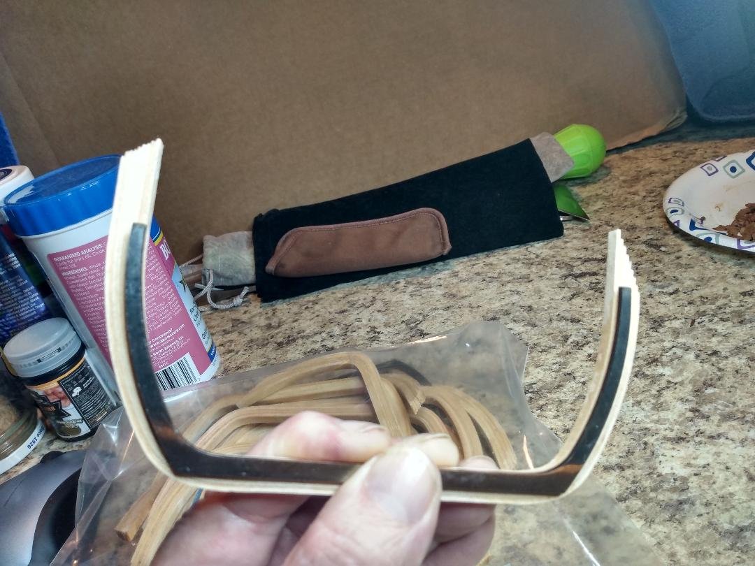
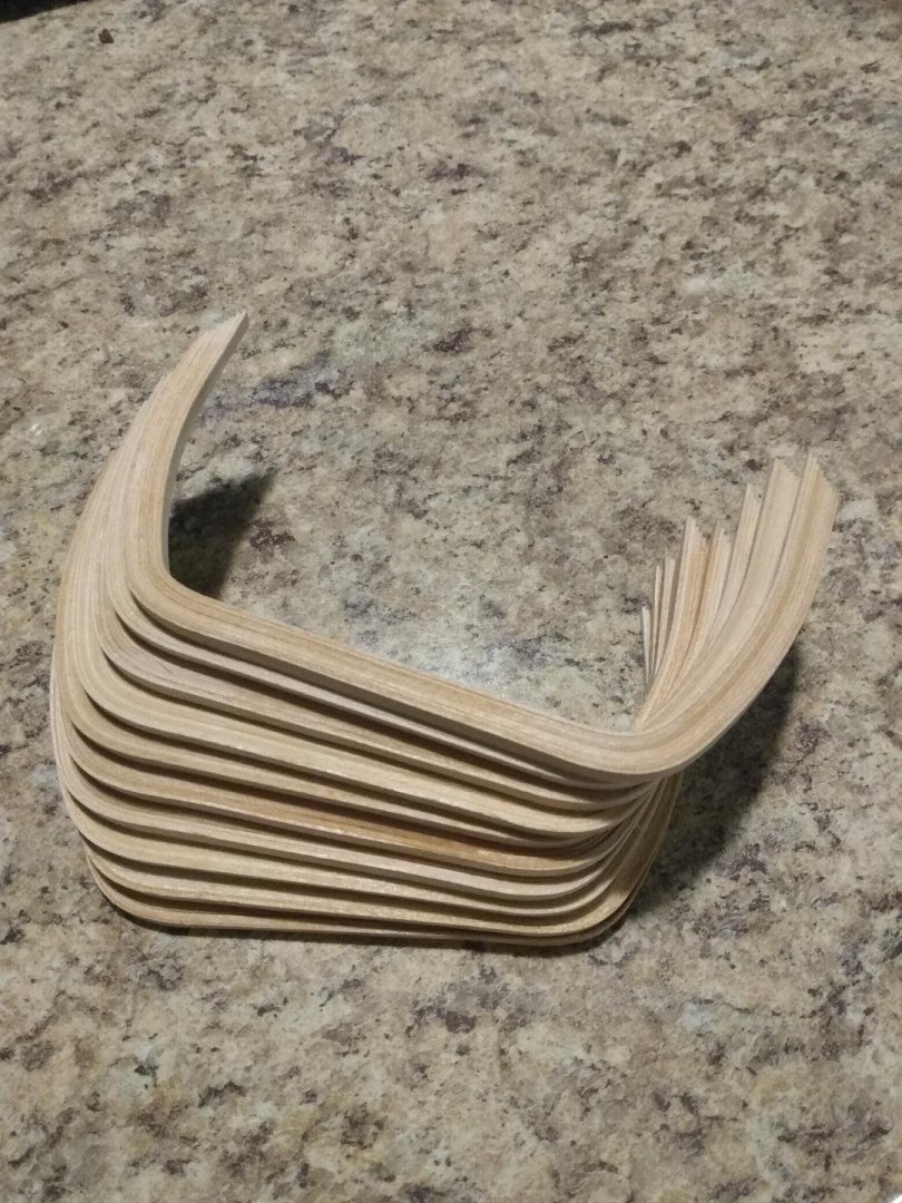
More work on the frames. I've now got 10 frames laminated together and ready to be cut/sanded to their final shapes. These ten sets will make 20 actual frames once all is said and done. As mentioned previously, I need 18 sets of these frames (36 actual frames) to complete the port and starboard mid-section of this build. I'll glue the remaining 8 sets together later. I normally don't like to use CA glue, but I'm using it for these frames to avoid spring back after gluing and 'hopefully' also ensure that the 9 ply laminated frames will not try to de-laminate or lose shape in the future. Here are the 9 ply frames after being bent around a form. The individual components hold their shape really well, however. There is about 1/16" of spring back on each vertical leg. I keep the bent frames in their respective bundles until time to glue them together. I start by gluing the flat bottoms together. I clamp the pieces in place around the bending form and then simply squirt CA over the laminations letting the resin soak in. I then pull the laminations around the form and glue the rest. After gluing the first side I remove the parts from the form and give the other side a shot of CA. There is no spring back, and the frames are quite solid. They will be easy to cut and sand to final shape during the next operation. As tedious as this sounds, it really goes pretty fast. It only took me an hour to glue these ten sets of frames together. Hopefully, the laminated construction will mimic the appearance of curved, hand hewed framing timbers once finished. I'll glue the rest together tonight while watching Svengoolie and waiting for glue to dry on my canoe build.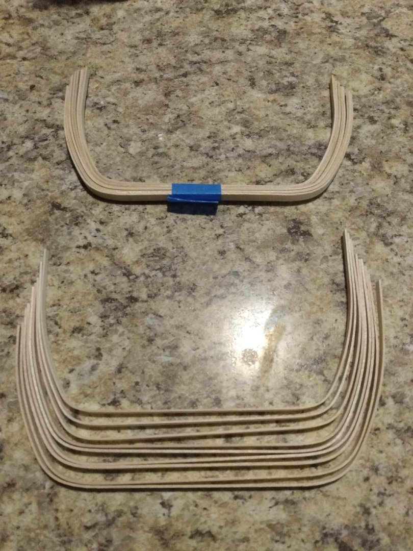

-
Very nice!
-
Very nice indeed! Job well done!
-
Nice work on those small parts! Pardon my ignorance, but I'm curious. What was the tallow used for?
- 732 replies
-
- 4
-
-
-
- Lula
- sternwheeler
- (and 1 more)
-
Gunboat Philadelphia 1776 by tmj
tmj replied to tmj's topic in - Build logs for subjects built 1751 - 1800
Haha Keith... no not nearly as tedious and mundane as those treenails. The frame construction sounds a lot worse than it really is. It's actually pretty easy. I do two sets of frames, after work each day. Maybe I'll bang out 6 or 8 sets Saturday and the rest Sunday. As for the treenail thing, the bottom of the bottom is complete. I still need to treenail the top (interior) of the bottom timbers. I'll do that as I inch along the bottom installing frames. -
Gunboat Philadelphia 1776 by tmj
tmj replied to tmj's topic in - Build logs for subjects built 1751 - 1800
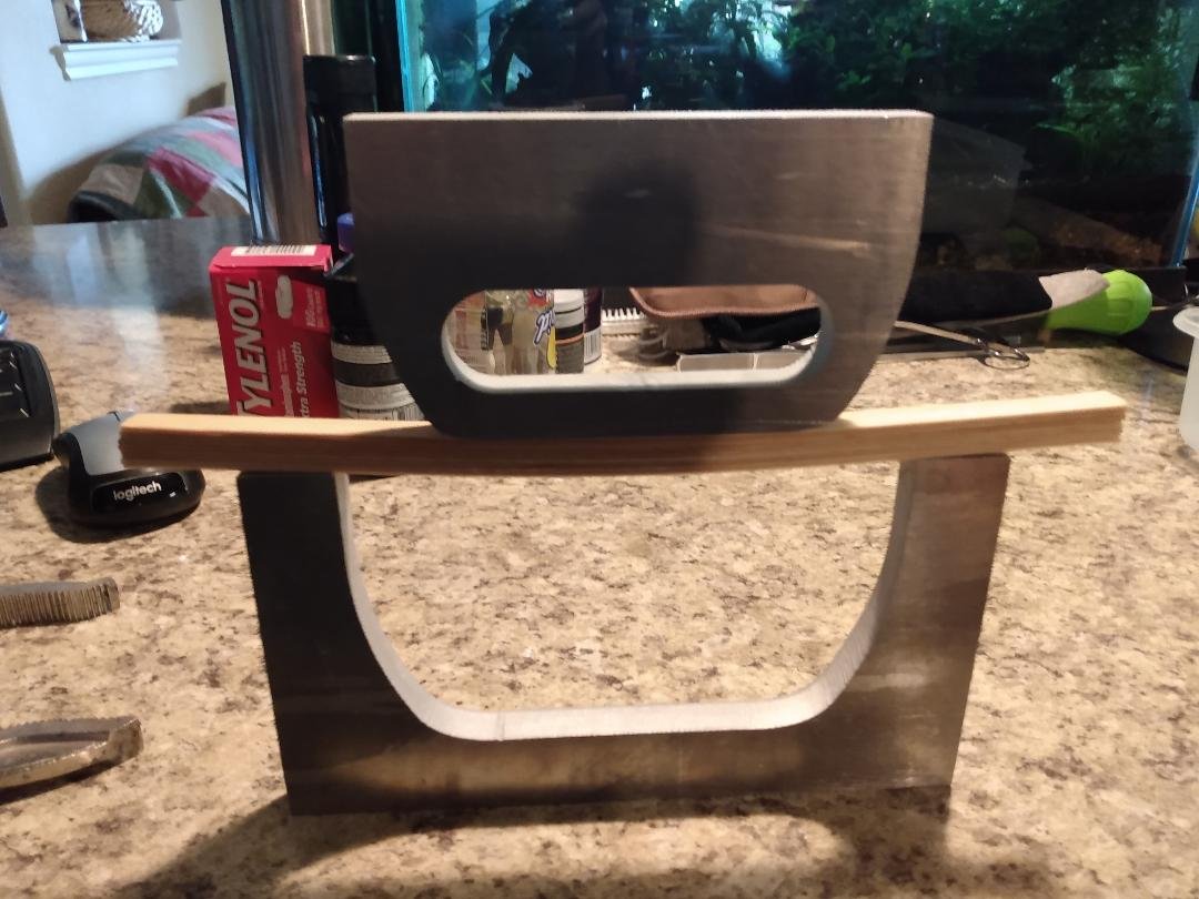
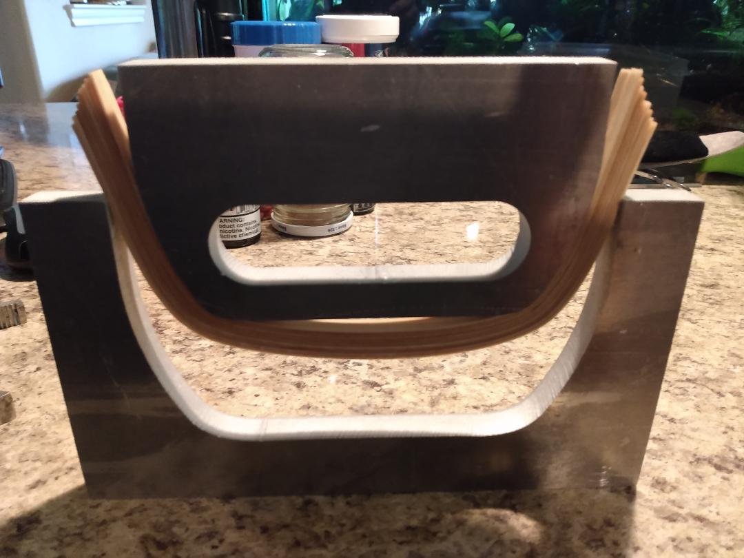
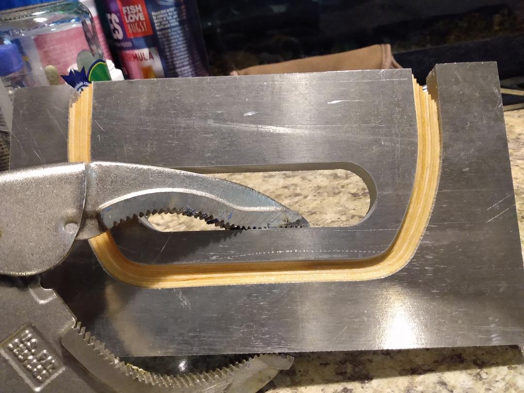
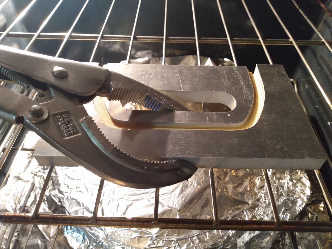
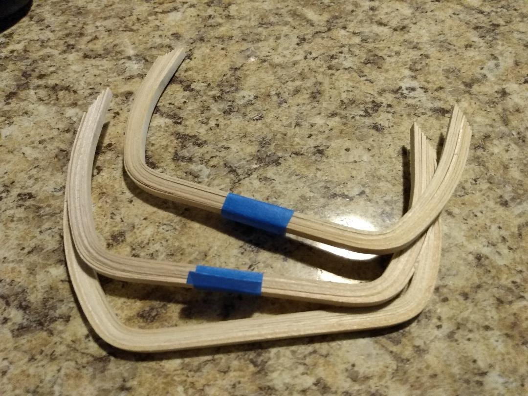
I modified my molding form and it works much better now. This is the process that I'm using to form the frames... I cut the 1/32" strips to an oversized length and loosely bundle them together with wire ties. I give them a 15-minute soak in really hot tap water while weighing the bundles down with a knife. I then remove the wire ties and lay the strips atop my form, centering them via eyeball. The strips are well oversized so there is room for error when centering. The fixture will hold two sets of frames at one time. No glue has been added to the strips. That comes later. I'm bending nothing but loose, wet wood. I then add the follower atop the strip bundles and center it up via eyeball. With everything centered, I start working the follower down by hand until I can't move it any further... then I use a vise grip to finish the job and compress the strips tightly between the two forms. I then bake the form and wood in the oven @ 210 degrees for a while, until mostly dry, then let everything come down to room temperature. When cool, this is what I have. I tape the bundles together and put them aside. I won't do anything else to them until I have all of the boat's mid-sections of 18 sets of frames bent. I'll then return these bent frames to the form and start gluing them up. I now have three sets of frames bent and two more sets in the oven. I'll be back after I get the remaining 13 sets of frames bent and ready for glue.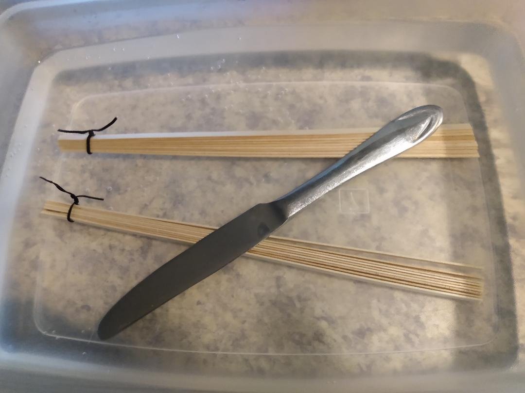
-
Gunboat Philadelphia 1776 by tmj
tmj replied to tmj's topic in - Build logs for subjects built 1751 - 1800
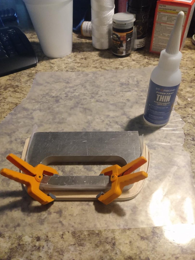
I added some CA and kept it clamped for a bit. There was about .060" of spring back on each side after un-molding. I'll make a new mold to account for this spring back and then bang out the rest of the frames for stations #13-#30.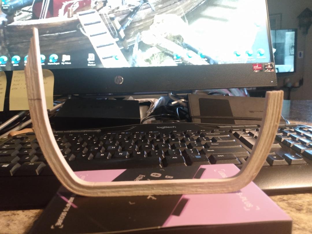
-
Gunboat Philadelphia 1776 by tmj
tmj replied to tmj's topic in - Build logs for subjects built 1751 - 1800
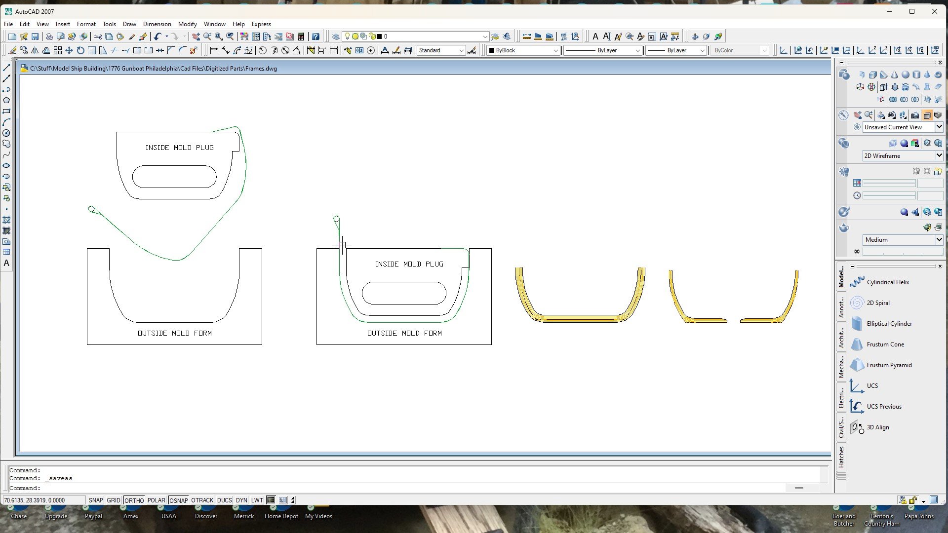
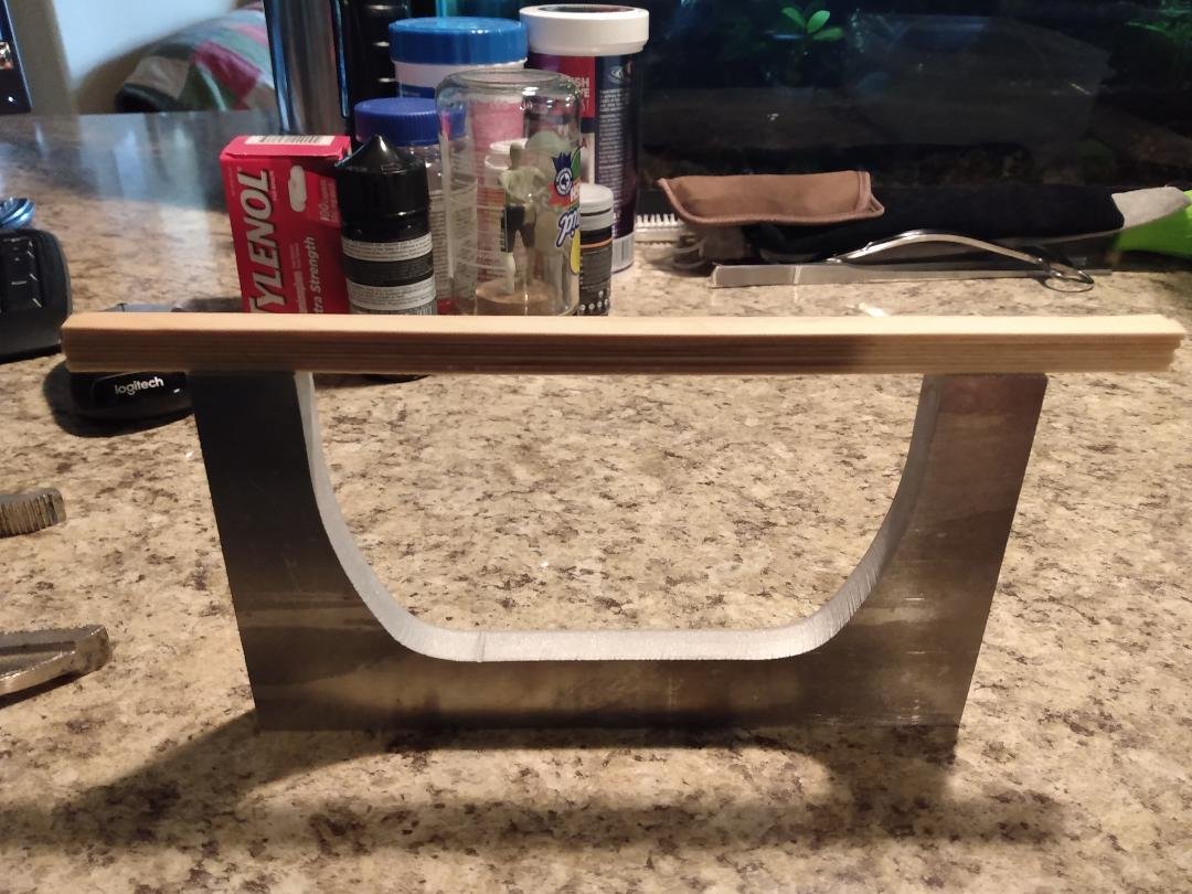
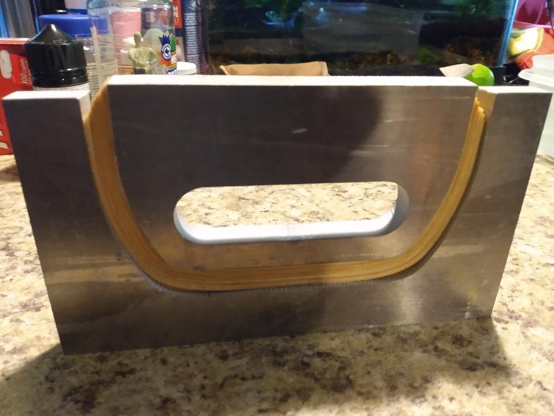
First set of frames taking shape. There are nine ply's of 1/32" X 3/16" Basswood strips clamped in this mold. No glue, just a test run to see what I'll be up against in bending the wood. So far so good, but I need to modify my mold a little to make it 'less awkward' in loading it with wood strips after glue has been applied to those strips. Each one of these rough moldings will make two frames, one port and one starboard. The frames molded in 'this' fixture will cover stations #13 through #30. The inside geometry of the frames is the actual internal shape. The 'outside' geometry of the frames will be cut to actual shape on the bandsaw.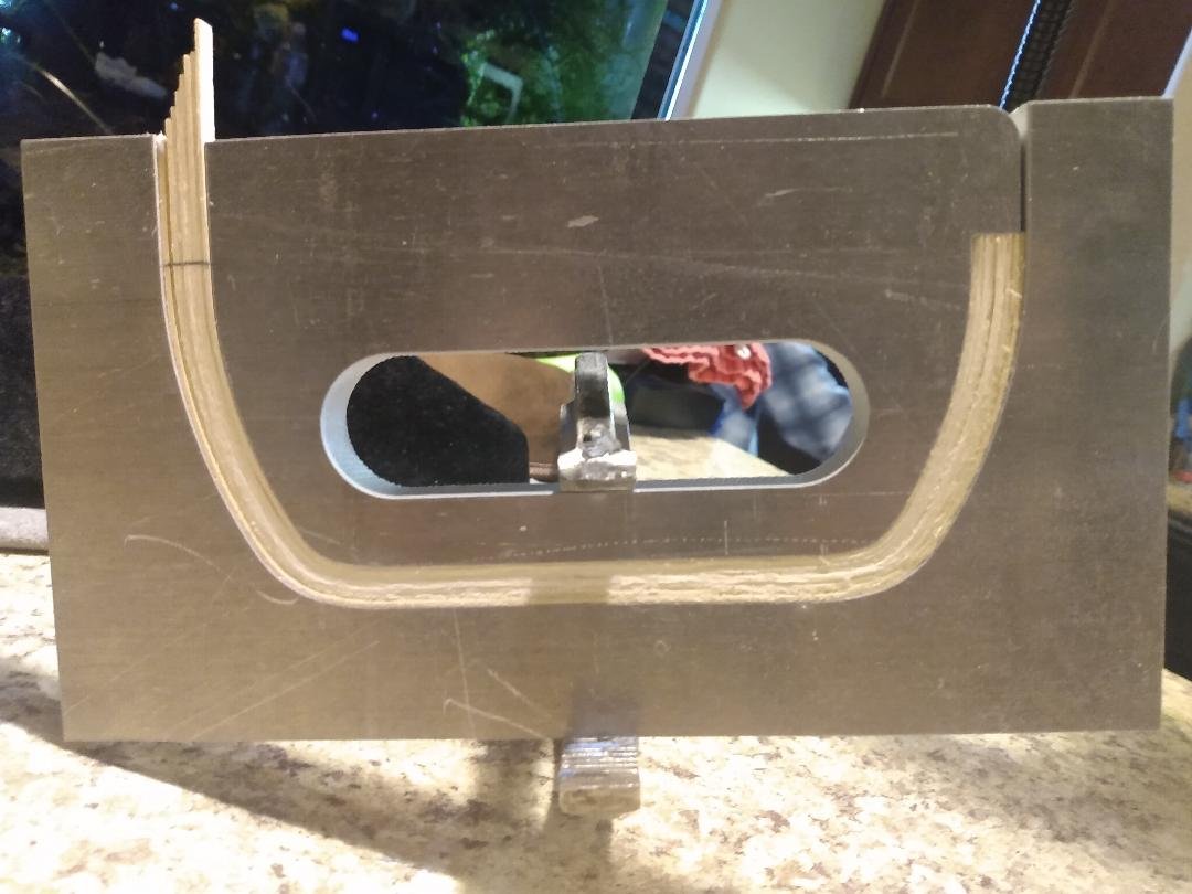

-
Gunboat Philadelphia 1776 by tmj
tmj replied to tmj's topic in - Build logs for subjects built 1751 - 1800
Back atcha, Keith... "Merry Christmas!" -
Gunboat Philadelphia 1776 by tmj
tmj replied to tmj's topic in - Build logs for subjects built 1751 - 1800
-
Gunboat Philadelphia 1776 by tmj
tmj replied to tmj's topic in - Build logs for subjects built 1751 - 1800
Howdy Keith! Yep, all is well. I'm just taking a little break right now trying to learn the ropes of tissue culturing plants and also studying up for an upcoming FAA part 107 certification. I should be getting back to work soon after the holidays. Have you started on 'your' newest project yet? -
Of course it will work! Endeavor to persevere. The more you try, the more you learn, the closer you get to perfection. An old Japanese proverb once said; "Fall seven times, stand up eight!"
- 185 replies
-
- 7
-
-
-
- Flying Dutchman
- Black pearl
- (and 2 more)
-
Well done, Keith! Definitely something to be extremely proud of! Can't wait until 'Lula' arrives!
-
Gunboat Philadelphia 1776 by tmj
tmj replied to tmj's topic in - Build logs for subjects built 1751 - 1800
My frame molding fixture was finally cut out today. I just need to have two holes drilled and tapped and the fixture itself will be 95% completed. The only thing left will be to shear the .0035" thick stainless steel backing strap and silver solder a loop into the pulling end of that strap. I'm hoping to get that all done this weekend so I can give 'er a test drive and bend some wood. Sorry for the delays. Home and work priorities have gotten in the way of progress lately, but I'm about to be able to get back on track. Thanks for bearing with me...