tmj
-
Posts
774 -
Joined
-
Last visited
Content Type
Profiles
Forums
Gallery
Events
Everything posted by tmj
-
 Quite true Mr. Aug! We can't truly see the deck on both sides. What I'm looking at is the location of the pilot house between the 'stacks'. The PH could very well be centered and what I'm seeing in my mind's eye is a simple illusion, however. To 'me' it looks like the PH is closer to the stack in the background than it is to the one in the foreground. Every time I study this photo I see something different. "Where's Columbo when you really need him?" 🤔
 -
It's very interesting how different eyes and different minds can see totally different things while viewing the same subject! 🙂 Sensible or not, this is what 'I' see. My railings abruptly end in space because the view of the rest of those railings is not visible. Only 'Billy' knows what's going on 'behind the scenes'. I also see the pilot house being off-centered. Doesn't mean it was. That's just how it appears to 'me' in the photo.
-
Something 'else' just caught my eye on this curious boat. What could 'this' be? The angle of its projection suggests that it's not just a 'wooden' feature nor a photographic anomaly, but rather something like a bent 'pipe' running forward out of the pilot house. Could this have anything to do with the indoor 'bar'? LOL

-
Knee-Rail

-
This appears to be a really low 'knee-rail' as well. Very dangerous, unless it's just to keep junk from blocking the pathway into the pilot house. Who knows. I'm just stabbing in the dark! LOL

-
I'm going out on a limb again. Could Billy have possibly had 'two' doors for the pilot house, one forward and one aft? I see what must be a handrail, and also some curious carpentry in the aft end of the pilot house. Could that irregular open panel on the port side be a door? Maybe there was a stair coming up from 'inside', not on the outside. One entered the pilot house from the rear end and came out on the upper deck from the forward door.

-
Hmm... The scale is obviously a bit smaller than what I was thinking it was! 😕 I didn't think of 'that'. Makes sense to me now. Maybe you can just add an electronic 'bicycle-horn' sound effect for your "tongue in cheek" representation, LOL
-
Maybe you could flare a small brass tube and glue a black bead on the end?
-
I don't like using rubber bands nor tape. I simple keep different sizes of stock 'loose' in different poly bags/sleeves... and store those individual bags of 'sleeved' stock in labeled round cardboard tubes, in an air-conditioned home environment. Works like a charm!
-
That's not a large model ship... "That's a small CANOE!" 😲
-
Holy smokes, looks 'GREAT'! "Very nice job, indeed!"
- 261 replies
-
- 3
-

-

-
- Victory Models
- Pegasus
- (and 3 more)
-
I have a question concerning scale and actual dimensions of ol' Billy. Was lumber for boats like this not typically milled to certain standards of the times, much like lumber is milled today? I'm asking this because of the different dimensions of lumber planks being used as 'siding' on the exterior of the 'above-deck' buildings. Could the width of those exterior planks/boards hold a clue as to the actual scale dimensions of the boat... or were things like lumber made with non-standard milling practices back when/where Billy was built? In guessing, I'd say the wide horizontal planks were around six inches wide and the vertical planks were about three inches wide. I came up with this by looking at the height of the windows where the wide horizontal planks are located. I might be way off base, dunno. I'm just looking for any known dimensions to accurately scale the photo by. I'm thinking that the dimensional lumber might hold a clue if known dimensions of that lumber can be revealed. 😕
-
Visit Seawatch Books for Swan Class plans, etc.
-
Very clever idea Glen! I'm late but will be keeping up with future progress for sure.
- 156 replies
-
- 4
-
-
-
- Queen Annes Revenge
- bottle
- (and 1 more)
-
"Whew!" I'm glad that this is plausible because my next thought had something to do with an extended stay at 'Zelda's Sand Bar', on fifty cent draft beer night... and you wouldn't want to model 'that'! LOL
-
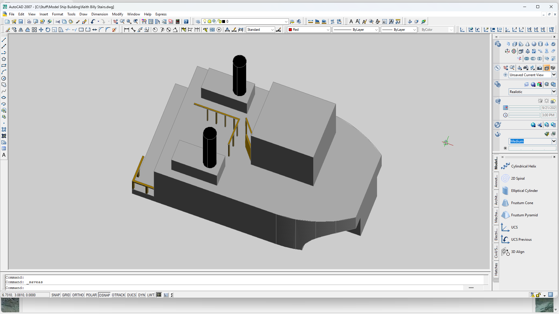
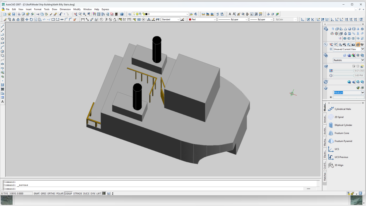
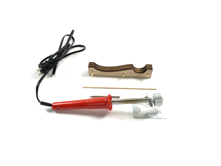
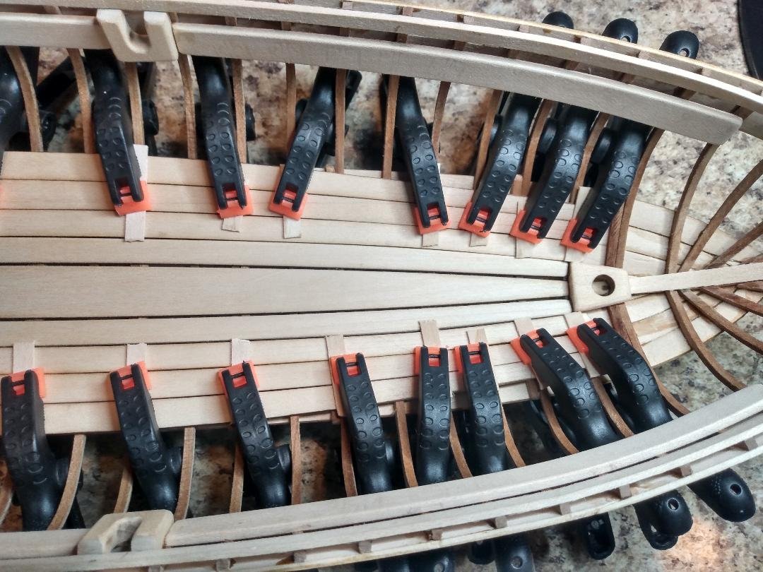
After my planks are properly 'spiled' to shape, I like to wrap them with paper towels then gently moisten the paper towels with tap water. Don't flood it until it's dripping water, just get the paper towels plenty moist and wrap everything in cooking foil for about 24 hours. If you are using a soft wood, you can then simply clamp those planks to your bulkheads or frames and let them dry until the next day. Soft wood will easily take all of the twists and curves while drying. Harder woods will need a bit of help via heat. I use the same process only I use heat on the tighter bends prior to clamping the moist planks onto the frames/bulkheads. This works pretty well most of the time, however. You'll probably need to work the harder wood planks with a bit more heat while clamped in place, and maybe even after drying overnight to conquer the tighter bends and twists. Don't get into a hurry and don't try to bend too far/tight in one heat. Sneak up on those tight bends a little bit at a time. You'll eventually get there! 😉 Once dry your planks will be ready for glue. This is my hot bender of choice. It works extremely well for 'me'. Here's a launch I'm working on. The three center floorboards are glued in place. The outer most floorboards are currently being 'wet-formed' to shape around the glued center boards, until tomorrow when they will be dry and ready to be glued down. This is soft wood with no tight bends so no heat will be required.
-
Could #1 possibly be hot engine 'cooling-water' being discharged back into the river? 🤔
-
I was once considering the 'Canal Boat Life', after retirement, in the UK where it's big, however. I own too many toys that I'm not interested in parting with. It wouldn't work. Most folks 'downsize' when they retire but I'm thinking that I'll need to 'Upsize'! I'd need a large canal boat plus a barge or two! I'd look like a floating Italian string of sausage links trying to get through the locks 'one link at a time'! 🫤 LOL
-
Don't challenge Keith on this unless you are feeling unusually 'lucky'! Keith 'WILL' pull it off and easily 'top' you're saying that he can't! ☺️
-
Keep the OOD on watch and closely guard those lines 'till construction resumes... less any land-dwelling critters find said lines amusing and quickly take it upon themselves to create adventure from any loose ends! 😲
- 261 replies
-
- 3
-

-
- Victory Models
- Pegasus
- (and 3 more)
-
"Sternwheeler - Houston, Copy." "Be advised... we're working on it............"
- 457 replies
-
- 2
-
-
- sternwheeler
- Hard Coal Navy
- (and 1 more)
-
Very impressive! "Opera Meritevole di Dei!"
-
Hold on. I need to find my jeweler's loop so I can see this better!
- 457 replies
-
- 3
-
-
- sternwheeler
- Hard Coal Navy
- (and 1 more)
-
Beautiful work, as always!