tmj
-
Posts
774 -
Joined
-
Last visited
Content Type
Profiles
Forums
Gallery
Events
Everything posted by tmj
-
 Carson definitely had the proper person work on this model! Very nice work... very nice indeed!
- 301 replies
-
- 3
-

-

-
- Constitution
- Bluejacket Shipcrafters
- (and 1 more)
-
Keith, this is going to sound a bit silly butttttttttttt!... #1... I did some really brief looking and didn't find any 'coal dredging' names on record, other than the 'Pennsylvania Water & Power Company'. I'd like to think that there were a few private contractors involved with that coal dredging business, but maybe not. Who knows... #2... Take a close look at that photo. I too can make out the words 'water and power' Co., but not the first word/name. Look at the 'length' of the written words "water and power". Each of those words are individually much shorter in length than the long unidentified 'first' word... maybe as much as half. It's possible that the first word 'is' indeed Pennsylvania but just doesn't look that way due to angles, worn paint, light, old photography, etc. Maybe you can do an in depth search into all coal dredging companies, in that area, and find a closer match to some names / letters that would better fit into that old photo...???
- 457 replies
-
- 7
-
-
- sternwheeler
- Hard Coal Navy
- (and 1 more)
-
Save that file! I could use a few of those in my 'Philidelphia Experiment' diorama! 🙃 LOL
-
That is true. I have the free 'personal use' version myself.
-
Hmm... I'm not sure about that one.
-
The Mossy Shipyard by Bryan Woods - 1:1
tmj replied to Bryan Woods's topic in Non-ship/categorised builds
Looks fantastic! You also need a small worktable, or work-'bar' on the front porch for those perfect days when the weather is "jusssst right"! ☺️ -
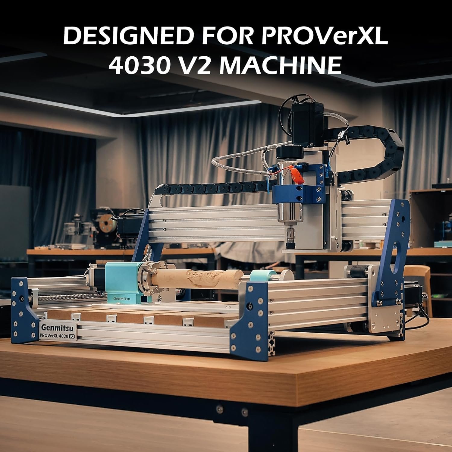
Most all of the CNC routers are 3D. The one shown in my picture is CNC 'plus' has that 4th axis (the horizontal lathe like thing in the foreground). Fox Alien and Genmitsu are popular brands. 3D capabilities are the main reason I went CNC.
-
Either connect to computer 'or' transfer files via flash drive.
-
I too considered a laser, but opted to purchase a tabletop CNC router instead. Cheaper to purchase, cheaper to repair and takes up way less space. No laser char to deal with either! You can also carve 3D objects with the router where you can't with a laser. The below CNC router, on Amazon, also sells a 4th axis accessory that rotates like a lathe for carving round items. I think, for the money, a good CNC router is a lot more versatile than a laser.

-
That is subject to your own personal feelings. Some folks would say it was worth it while others would disagree. What it is worth to 'YOU' is all that really matters. 😉
-
Perhaps this 'clause' is 'someones' way of leaving the options for planking and caulking open, in the contract, without holding things up at the shipyard?
- 490 replies
-
- 2
-
-
- minesweeper
- Cape
- (and 1 more)
-
What Am I Missing
tmj replied to acaron41120's topic in Building, Framing, Planking and plating a ships hull and deck
Heavy emphasis on 'paper'! The thinner the better! Thickness creates errors. The thicker the paper, the more exaggerated the error. 😉 -
I designed this push-broom many years ago. What separates this broom from all the rest is that I designed it to be pushed by 'someone else'. It's been a big hit!

- 732 replies
-
- 9
-

-
-
- Lula
- sternwheeler
- (and 1 more)
-
Nobody can tell you what you are truly capable of accomplishing... not even yourself! If you find something that you like, "Go for it!" Take your time and advance your skills as you go. Practice any new operations that you are unsure about using scrap materials first. Odds are that you'll do just fine on any model that you choose! Confidence is a big thing, and confidence comes from building upon past accomplishments via new endeavors. Don't view the somewhat more advanced skill level of the Syren as something to be afraid of... see it as your newest achievable 'goal' to take on! 🙂 "Our doubts are traitors that make us lose the good that we oft might win by our fears to even attempt!" ... William Shakespeare
-
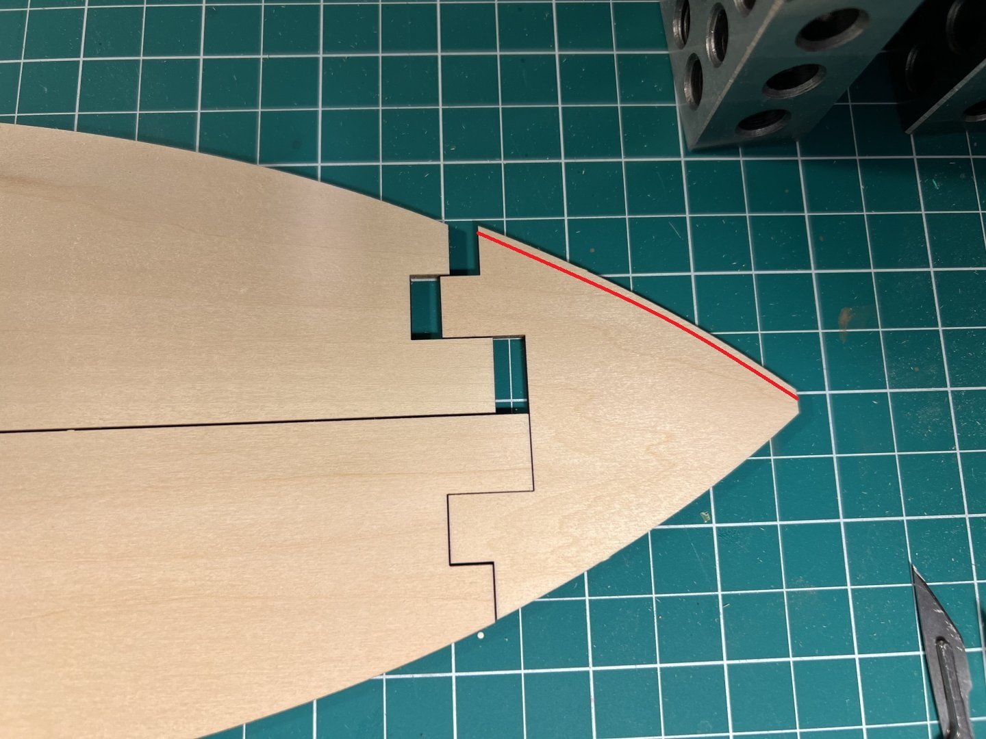
It looks as though you are going to lose your centerline at the stern which is going to force you to reshape the bottom back there making it 'lopsided'. Have you taken measurements back there? I think I'd order a new bottom and save a lot of grief.
-
Great job, Giampiero! Your work is very beautiful!
-
If it were 'me'... I'd have designed those wings so that they could be quickly removed for battle and bad weather! 🫤
-
My sentiments, exactly! Great job, Glen!
- 301 replies
-
- 4
-
-
-
- Constitution
- Bluejacket Shipcrafters
- (and 1 more)
-
I don't know if this is true, but I read somewhere that while in port ships were often docked with their bow facing into the wind, if possible, for various reasons. If this is true your constitution is parked backwards, evidence via the direction that the flags are blowing. 😐
-
Homemade Chisels?
-
Nice carving detail!