


tmj
-
Posts
305 -
Joined
-
Last visited
Content Type
Profiles
Forums
Gallery
Events
Posts posted by tmj
-
-
Hmm, one more question. "How were those stanchions/pillars, etc. actually 'anchored' in place?" Would it have been via tongue & groove, or what? This obviously has no value in the building of a small model. It would just be nice to know...
-
I think my mind is made up. I'm going to use square stanchions in the hold and also between the Orlop and lower gun deck. All other pillars/stanchions/whatever's that will be supporting the upper level gun decks will be squared on the ends and turned in the middle, just like post #6 depicts. Bear in mind... post #6 is nothing but a concept of how I intend to fabricate those stanchions. It is 'NOT' anywhere close to the exact geometry that I will truly be using!
I truly appreciate everyone who has chimed in on this subject.
Many thanks!
Tom...
-
20 minutes ago, Gregory said:
I realize, without further evidence, we cannot assume the ship was built as drawn.
We also cannot assume that it wasn't! I totally agree with you as per the shading! All in all, This goes back to #1) on my list of curious things to consider!
- Gregory, Keith Black and mtaylor
-
 3
3
-
I'm still struggling with the true 'geometry' of these posts/pillars/stanchions... whatever the true nomenclature actually is. My issues are based upon structural integrity, cost effectiveness, and time constraints. Without getting into details and diving down a lot of deep 'rabbit-holes'... I'm beginning to wonder if 'anyone' will ever know the truth!
#1)... I understand that way back when, folks took a lot more pride in their work and skills than folks seem to do today. They had very crude tools, very strong backs and finely honed skills worth being proud of!
#2)... Materials, labor and time. Ornate posts/pillars/stanchions would produce excess amounts of waste requiring a great deal of time/labor/money in creating all of that unusable waste for the sake of aesthetics!
#3)... Engineering. There would be no advantage in having the ends of these posts/pillars/stanchions larger than the mid-sections of the so-called posts/pillars/stanchions except to provide better 'footing' upon the surfaces upon which those posts/pillars/stanchions would be mounted, for 'whatever' reason. Those large square ends would serve no other purpose. If the posts/pillars/stanchions ever failed, they would fail within the smaller profile of their mid sections. I can also see the 'thicker' tops and bottoms cracking, due to fatigue from the ship pitching, rolling and twisting as ships must be able to do. Those enlarged, square tops and bottoms actually create certain shear points that would eventually crack and fail. No real structural integrity. Pure aesthetics and footing.
All that being said... were ornately carved posts truly used back in those days, or were such artistic designs simply the initial products presented by desiring architects, who's ornate ideas were eventually turned down, for many reasons, and replaced with things more practical with the original drawings still remaining simply out of flare and pride from the designer? Maybe creative licensing by authors wanting to make their works more appealing to potential buyers has had an influence on the material we now examine? Let's not forget museums... unless you think that I'd be historically accurate in building HMS Victory, as per the current vessel, as she sits in Portsmouth's Historic Dockyard. This sort of research into factual historic details is becoming very curious, as well as confusing!
There's obviously a bit of "Tongue & Cheek" going on with the content of this post. I hope that this post does not open up a huge can of worms. That is not my intent. I'm just beginning to scratch my head and wonder if the truth is really out there at all! Halloween is approaching. Maybe someone knows of a spiritual medium who can channel the spirit of a sailor who was onboard Victory during Trafalgar? Some of that 'automatic writing' might give us all some good drawings of period correct posts/pillars/stanchions, etc.!🫠
In case anyone missed it. This post is about posts/pillars and stanchions! 🙃
- mtaylor, GrandpaPhil and Keith Black
-
3
-
16 minutes ago, Gregory said:
Making them 'square' in the middle would have been a lot more work than rounding them off with the given dimensions.
Making them round, or somewhat pyramid shaped, as the description reads, would 'BOTH' require a lot of unnecessary work! I'm thinking that the description is a bit loose in language, for the time period, and also leaving a lot of room for modern day interpretation.
- Keith Black and mtaylor
-
2
-
13 minutes ago, GrandpaPhil said:
McKay said he based his data on the best current thinking back in 1987.
Hello Grandpa!
I have that book, and it is a very 'fine' book, however. Its data, as accurate as it is, is also based upon cumulative refits, reworks, modifications, etc. that have taken place over a very long period of time. The ship that McKay based his data upon is not the same ship as it truly was back in 1805. His book is based upon the latest version(s) of that ship, after re-fits, during our more modern times.
'McKay'... I really like that name... only not so much 'John' McKay as that of 'Donald' McKay! Every time I think of Donald McKay, I start having visions of a 'Flying Cloud'! 🙂
- mtaylor, GrandpaPhil, Keith Black and 1 other
-
4
-
On 9/18/2023 at 6:25 AM, allanyed said:
According to contemporary information in David Steel's 1805 Elements and Practice of Naval Architecture
Allan,
I now have a link to David Steel's 1805 Elements and Practice of Naval Architecture. Could you please tell me what page number you found this data on?
Thanks,
Tom...
- Keith Black and mtaylor
-
2
-
10 hours ago, allanyed said:
According to contemporary information in David Steel's 1805 Elements and Practice of Naval Architecture
Thanks Allan! I was about to make another major, historical error via the geometry of the Orlop and gun deck(s) pillars/stanchions. If I am understanding the content of your post correctly, I will 'NOT' need a lathe for 'any' of my stanchions and or pillars if I am to pursue an 1805, Trafalgar configuration! If that is correct, that's also 'great', however. I'm not out of the woods yet! I now need to know just where those pillars/stanchions were actually placed, athwartships, with the keel being used as a centerline reference point. I do not trust any of my reference material for the 1805 era. You wouldn't happen to have 'that' data too, would you?
Regards,
Tom...
- Keith Black and mtaylor
-
2
-
12 minutes ago, Keith Black said:
TMJ, I didn't realize you needed post. You'll have to make those yourself. Because you have a lathe it shouldn't be a problem.
Not a problem, Keith. I typically 'think' better than I speak or type. I'm often unclear in accurately describing exactly what's going on in my mind. I should think a bit more before starting to haphazardly bang away on my keyboard!
As for having a lathe? It's a nice pet to have, albeit. These are small parts and I'm not so sure that I'll be able to pull this off as easy as I Invision it, nor be able to accurately 'repeat' the same, exact process 24 times! 😶Something tells me that we will 'all' find out, very soon, just how well I can make a handful of custom stanchions DIY. "Fingers are crossed!"
- Keith Black, mtaylor and Dlowder
-
3
-
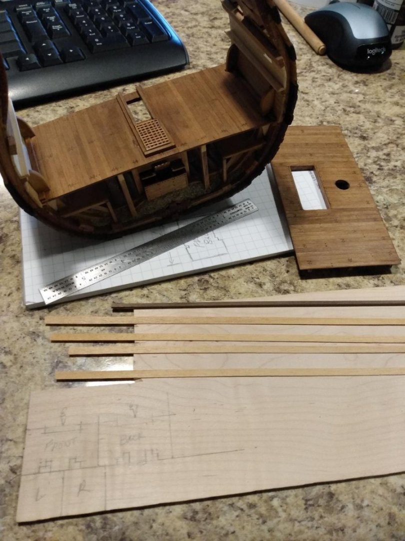
I do have a mini lathe and have thought about the exact same process that you described. I also came up with another idea that requires the use of a dowel that is much larger than the required stanchion diameter at its widest diameter when completed. Turn the round portions and details on the lathe and 'then' put the round piece in a 'V'-Block, lined with sandpaper, and square off the ends... somewhat like the concept below.
.thumb.png.9fb91feb437b3360b064c22e381b873d.png)
- Dlowder, mtaylor and Keith Black
-
3
-
On 9/13/2023 at 4:45 AM, Darius359au said:
I didn't like the look of the hold pillars
I agree with you. What is supplied in the kit is quite lacking in both interest and also perceivable reality. Real 'cheesy' looking at best. I did the same thing that 'you' did in my bilge too, with the pillars. It's truly a much better look and closer to reality. I'm now currently struggling with the deck stanchions that will support all upper-level decks. I've so far found nothing for sale that looks even remotely realistic and I'm now thinking that I might actually have to painstakingly make my own stanchions. That will surely be more easily said than done, and also take a lot of trial and error in figuring out just how to carve such tiny things, in a micro lathe, without breaking those tiny parts as they are being turned. If I happen to get lucky in finding a source for realist Victory deck pillars, at 1:98 scale, I'll let you know!
- Dlowder and Darius359au
-
2
-
This is as far as I can go in completing the Orlop deck's section of pump well housing, until I can either locate a source for proper deck stanchions, or finish making my own stanchions, which will take some time. I need those stanchions to properly 'arc' the lower gun deck and also effectively set the well housing true to its final 'situation' between those two decks. I'll then be able to complete the planking on the well house, trim it out and make it look proper. That's okay. I have plenty of 'other' needful tasks to take care of until I'm ready to finalize the well house.

- mtaylor, Darius359au and Dlowder
-
3
-
-
Thanks Keith! Those stanchions look great, however there are two problems. They are a bit too short, and they are also not to scale as per proper geometry. They just don't look proper for the HMS Victory gun decks. I'm probably going to have to make my own, due to what seems to be available for sale, but who knows. Somebody might know of an obscure source where these things can be bought. That's what I am hoping for.
-
Does anyone know of someone who sells these things? I don't want 3D printed plastic; I want real wood. I'm trying to avoid having to make these tiny things myself, unless I have no other choice.
- GrandpaPhil and Keith Black
-
2
-
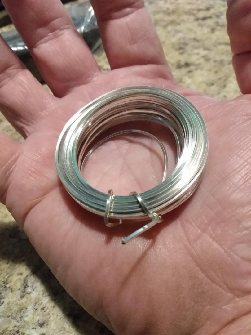
My 'Pigs of Iron' ballast material just arrived. "Woo-hoo!" This is 1.5mm 'square' copper wire that has been plated with something shiny. At 1:98 scale, this stuff will represent iron blocks approximately 6" X 6" square. After a lot of soldering and suffering from plenty of heat, I doubt that this stuff will look very pretty once all is said and done. It'll likely look more like ugly crude iron, which is the effect that I am after.
I'll obviously have to remove the shingle ballast that is currently glued into my model, to make room for the 'Pigs of Iron', which was an afterthought, but that's okay. The end result will be well worth the extra effort required. After installing the pigs, I'll re-apply shingles as needed to make things look proper.
-
I'll get back to the ballast in due time. For now, I'm going to start moving upward and build the second story of the pump well housing between the Orlop deck and the lower gun deck. Not too difficult. Getting a nice tight fit, with no ugly gaps will the most challenging part of this.
- Darius359au and mtaylor
-
2
-
-
18 hours ago, Morgan said:
The fundamental choice in this debate is to what time period are you modelling your cross section.
Gary, I have no idea as to the time period. I started this model only wanting to build a descent looking specimen, worthy of display, within my limitations of skill. No historic significance was ever considered. That has obviously changed, but there have already been many 'creative' mistakes made along the way, as per historic accuracy of 'any' period in time. I cannot reverse those mistakes, however. I'd like to abstain from making any future mistakes as I proceed with this build.
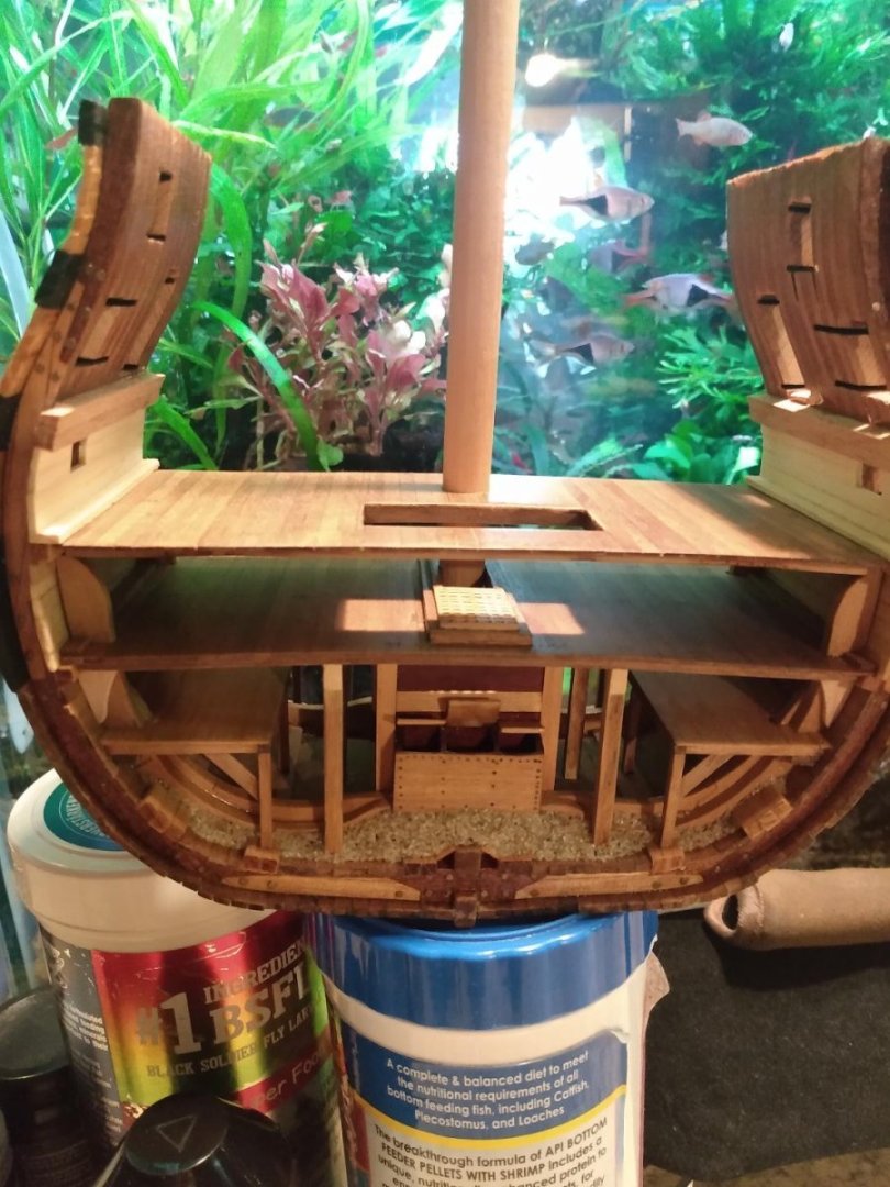
In viewing the above photo, mistakes and all... you tell me what time period my model, in its current state, would 'most closely' represent. I'll then locate, purchase, etc. the proper reference materials for that specific time period and proceed accordingly. I'm thinking that 'this' may be the best way to get me moving on a proper, less confusing trek!
regards,
Tom...
-
9 hours ago, allanyed said:
Which reference books are you referring to?
Hello Allan,
My main go to has been "The Anatomy of Nelsons Ships" by Longridge. There is another 'old' book in my collection, that I recall, but can't seem to locate at the moment. I'll have to go digging for that one before naming names. I also just received John Mckay's book "The 100-Gun Ship Victory". It arrived today, so I have not had time to look at it. It's quite possible that the information that I seek truly lies within the books I have been looking at and I've just not delved deep enough into those books to find what I seek. Perhaps the info is in McKay's book. Time for thorough research is something that I simply do not have right now. It's all I can do to get a few hours of work done on my model every week. Research will have to wait about four years, until I retire, then I will have all the time in the world for both research and building.
-
I have two reference books showing these iron braces attached to hanging knees. Those iron braces are shown with dotted lines, which to me means that they are 'hidden' lines, lines showing something that is not on the front side of the view being shown, but rather on the back, 'hidden' side of that view... like a mechanical engineering drawing. I've also looked at photos, online, but those photos never show both sides of the knee brace. I'm confused. Common sense tells me that those iron braces need to be on 'BOTH' sides of the hanging knees, but my drawings show that to not be the case, via those hidden/dotted lines. The image below shows the current progress on my Victory section. I need to know if displaying iron braces on the visible sides of the hanging knees, supporting my Orlop deck, would be proper, or improper.
-
Bob Cleek and Mark P... thank you for the information. You folks have been 'extremely' helpful on this subject. I 'will' be displaying limbers, hanging out of the ends of my sectional model's limber channels, however. I'll not be using chain. My limbers will be constructed from scale sized rope and designed to function in the manner, and for the purpose described by you folks in your posts. As for bilge cleanup and sanitization... I'll leave that to the 1st Lieutenant division, and those who are on punishment detail as a result of disciplinary action and/or Captain's Mast! 😗
-
While gazing at my model, I realized something. I just missed a 'GREAT' opportunity to display the true ballast of this ship, known as "Pigs of Iron". There needs to be bare 'ends' of "Pigs of Iron" protruding from the shingle stones on each end of this sectional model. I'll note this change order and take care of it ASAP. I can easily grind the ballast out with my Dremel, insert the pigs, then re-ballast around the little piggies! That should make for a wonderful historic effect! I can even rust the little piggies a bit before installation. I now just need to find out exactly how these pigs of iron were truly laid out within the bilge, for proper scale appearance. I thank members 'Morgan' and 'allenyed' for 'this' fantastic bit of inspiration in my build! "Thanks Gary, thanks Allen!"
-
This is all fine and dandy, but we seem to be getting off topic. How did the British use their limber chains if and when they were used? Would there have been one chain per channel, or maybe 'two' chains per channel? If anyone can come up with anything definite about this, that would be great. If not, I'll take advantage of my right to artistic licensing and just do something that looks nice whether it is accurate, or not.
.png.5e8feb9f5b55362e1524f08ccee7a97c.png)

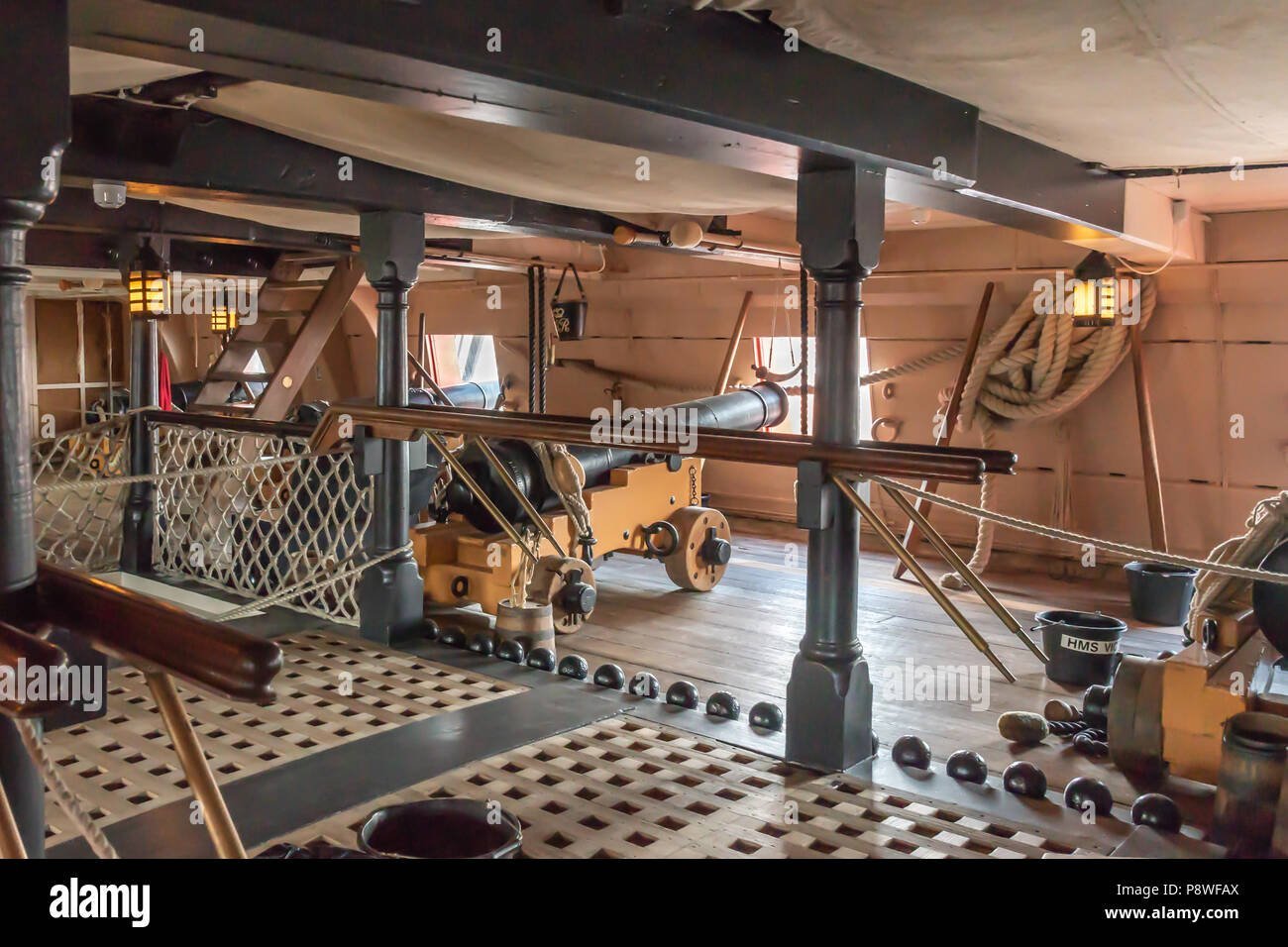


Handrails on Ships Ladders, Stairs, etc.
in Discussion for a Ship's Deck Furniture, Guns, boats and other Fittings
Posted
I'm dry fitting parts atop my HMS Victory Orlop deck so I can start staring at things, scratching my head, and thinking forward as to where I want to go via this phase of the model. When I look at these ladders, or stairs, I can't help but to wonder if any kind of a 'handrail' system was ever incorporated on such 'Ships of the Line' in 1805? Perhaps, HMS Victory was a heavy, sluggish ship that didn't roll too much, somewhat like a modern day 'Aircraft Carrier.' Maybe handrails were unnecessary, then again. Maybe handrails were used, just not shown in most drawings? I don't have a clue. Back in the day, my squadron was attached to the USS Coral Sea. She didn't roll much, except when hard turns were being made to the starboard, due to the old wooden 'angle-deck' being replaced with heavier steel to accommodate jets. It was a weight/balance thing. Anyway, we had handrails aboard that carrier, but didn't really need them most of the time. Did Victory have rope, or wooden handrails on ladders such as this?