


tmj
-
Posts
760 -
Joined
-
Last visited
Content Type
Profiles
Forums
Gallery
Events
Posts posted by tmj
-
-
47 minutes ago, Knocklouder said:
@tmj you know how modelers tend to great exaggerated the size of thier ship lol my next build will be a Wasa and it is only 38 inch lol. Still bigger then the Harriet Lane.
At least you are honest about size! I too try to avoid exaggeration whenever possible, however. I'll never forget that that time when I caught a Brook Trout in this little, teeny, tiny mountain stream that was 'Thisssssssssssss' BIG! 😮
- Knocklouder, GrandpaPhil, Keith Black and 5 others
-
 1
1
-
 7
7
-
-
17 minutes ago, Knocklouder said:
Well I know that this will be my last 1:144 scale model that I will do. This and anything smaller is very difficult to do. I am not happy with my work at this scale, My next build is almost four feet long, 7 mm deadeye that the 3/32 can almost pass through the holes lol.
I hear you! 1:76 is currently 'my' limit, no smaller than that! Old eyes, old hands and way too much frustration involved in messing with the really small stuff.
What is that next build, at four feet going to be?
- Keith Black, Canute, robert952 and 2 others
-
5
-
That 'scant' amount of rope is only used to hold the anchor up. You can see the actual anchor chain going into the hawse hole, below deck, to where the rope, capstan and rope storage would be.
Here's a short video that might help you understand how everything works. It's a different ship, but the same principles would still apply.
- Stevenleehills and mtbediz
-
2
-
It's time for me to leave this thread. Find whatever tools suit you best. That's what counts.
Good luck and Happy New Year to you!
- Ronald-V, Keith Black, MintGum and 1 other
-
4
-
20 minutes ago, MintGum said:
Do you use your mini chop/cut-off saw to cut deck planking?
Please reread my responses. I've already answered that, as well as your OEM questions a few posts ago.
- Canute and Keith Black
-
2
-
Sorry, but you were asking for opinions from folks with firsthand use of certain tools. You got those opinions then quickly switched to OEM. If OEM is more important than how well the tools work... maybe, you need to rephrase your question and ask again on another thread. Useability and OEM are two totally different things.
Good luck!
- Canute, MintGum and Keith Black
-
2
-
 1
1
-
2 minutes ago, MintGum said:
As is often the question, what was the OEM(s)? Amazon, Vevor, Harbor Freight, Micro Mark, etc... all appear to be copies of which OEM?
OEM? Some Chinese company, I'm pretty sure. Chinese companies ripping each other off, in competition, to see who can effectively grab the biggest market share before some 'other' Chinese company takes them down! Who cares? The darned things simply work... despite there being a hundred different labels of the exact same silly thing! LOL
- Keith Black and Canute
-
2
-
20 minutes ago, kurtvd19 said:
Harbor Freight sells this saw for about 1/3 or 1/4 of the cost of the Micro Mark version
If I'm not mistaken, Harbor Freight is where I bought mine way back when!
- Keith Black and Canute
-
2
-
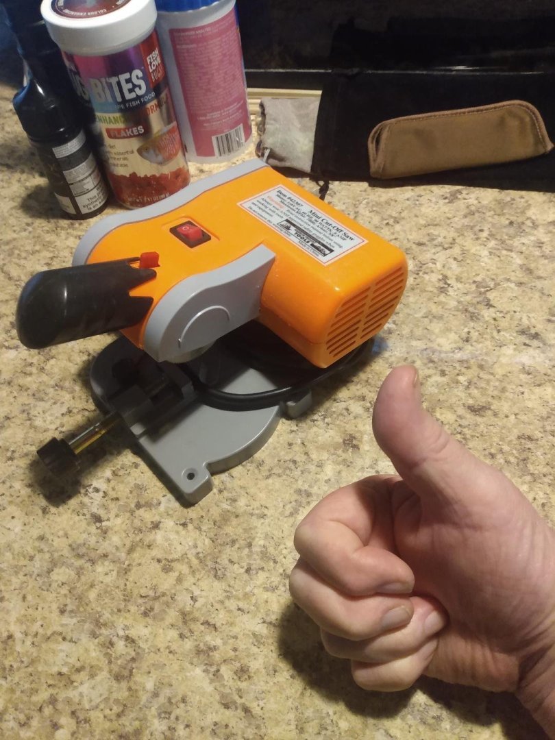
15 minutes ago, MintGum said:
Please post a picture of your 20 year old unit.
Here 'tis! 😁 I've cut tons of stuff on this little thing, mostly hardwoods. It's really a great little tool, despite its origins and price! As for 'thin' stuff? It'll cut a 1/32" thick plank, or a 'stack' of 1/32" thick planks just as easily and pretty as you please! Nice clean cuts even on the thin stuff!
- Ryland Craze, Canute, MintGum and 1 other
-
4
-
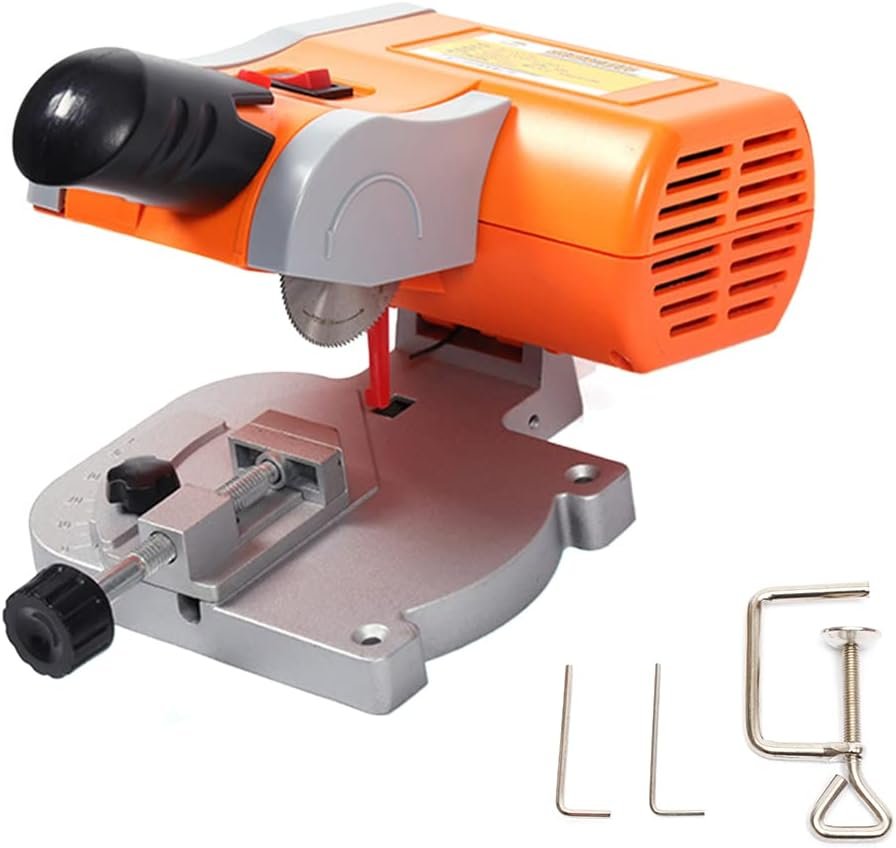
This is kinda goofy but works 'GREAT' for square cuts on thicker stuff that the Ultimation won't like. It's cheap too! Look for mini table saws on Amazon. I've had mine for 20 years and it still works like a champ!
- Canute and Keith Black
-
2
-
I have the complete 'Ultimation' line of products and love them all. The chopper will indeed cut a bevel on one end, but I deal with that in one of two ways. If it's planking, I'll often use that bevel to my advantage by turning the points 'up' and making a really tight butt joint against the preceding planks. If I don't want the beveled cut, I simply cut my pieces a tad long and use the sanding repeater to sand all of those parts to exact lengths while also removing those tapered cuts. As for the hand powered sander, itself. It is a gem, indeed. It's saved me many times when the complex geometry of a curious part and compound angles would make it difficult to accurately sand such a part via a powered disk sander where you must sand on one side of the disk due to rotation, etc. With the Ultimation sander, I just turn the crank in whichever direction best suits the needs for the part needing to be sanded. I have nothing but 'PRAISE' for all of my Ultimation tools!
- palmerit, Ryland Craze, MintGum and 1 other
-
4
-
-
-
-
1 hour ago, Keith Black said:
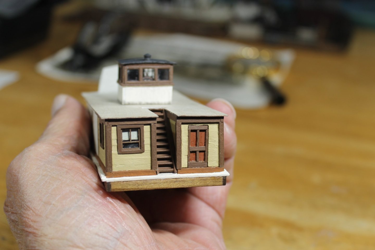
"Holy Cow, Kieth!" "You are the 'Stairmaster' for sure!" That is gorgeous! Extremely fine detail and precise work, without a doubt! "Very impressive", I 'love' it!
Now I know why it's taken you so long to post any updates to your build! 😮
-
A quick IP search produced the following results.
🌐 IP Address & Hosting Location for artesanlalatlna.com
The domain we need to analyze is: artesanlalatlna.com
❗ First important note
The search results did not return any direct IP address or hosting information for this domain. That usually means one of the following:
• The domain may be very new, mis-typed, or not widely indexed.
• It may be using CDN protection (Cloudflare, Akamai, etc.), which hides the origin server.
• It may be a clone site or scam storefront, which often use masked hosting.
- Ronald-V, hollowneck and Baker
-
3
-
Not much that I can add to this beyond what Chris and others have said. You 'must' be cautious these days! Know what you are buying, know what it is actually worth, and always carefully read the web address!
Scammers are getting really clever these days.
- thibaultron, vvvjames, Ryland Craze and 1 other
-
4
-
-
8 hours ago, wefalck said:
There has been also for centuries, if not millenia, an extensive trade in stones of particular properties.
Makes sense, good sense, however. What about general merchant vessels, their needs regarding ballast, etc.
Desirable properties of stones, or not... "ballast is ballast to those who need it." For those with an entrepreneurial mindset (probably everyone) ... I'm sure that offloaded, unwanted 'simple' ballast was a commodity often 're-sold' to those effectively needing to 'onload' such 'simple' ballast! A fee would surely be charged for the labor required to off-load that undesirable ballast, from one ship... then when 'another' ship was actually 'needing' ballast... 'that' captain would not only be charged for the labor to load the ballast onto his ship, but probably 'also' be charged for the ballast material itself! "One man's junk = 'another' man's bankroll X2!" I can see 'useful' ballast being used in the form of 'goods' being transported, but what if there was no market for those heavy and specific goods at a needful ship's destination. Junk ballast would need to be used, would it not? Would this type of ballast have been traded back and forth, for a profit, at ports? I'm just guessing here. Sounds like it would have been a good way to make some easy money back then! (Easy for the proprietor, not so much for those unloading and re-loading the ballast stones) 🤔
-
What type of gaps are you looking to fill, and just how big are those gaps?
-
-
Buy from 'known' reputable sources and support the folks who actually go through the motions of designing that stuff with hopes of maybe earning a dollar or two for their long, tiring efforts. Don't support the Chinese pirates that simply 'steal' hard earned intellectual property, make inferior copies and effectively drive the cost of the truly good stuff up much higher than it really 'should' be, via the basic laws of marketing, supply and demand. I might ruffle some feathers here, but I honestly don't care. "I hate 'thieves'!" As soon as I see country of manufacture being 'China', I quickly walk the other way! As tempting as the price 'always' is, I also know that the product is either stolen or extremely inferior in manufacturing quality! "Just say 'NO' and pay a few dollars more!" You'll be supporting legitimate, hardworking inventors and craftsmen, as well as preserving the integrity of great quality in the needful products being sold to us hobbyists! "Don't buy ill-gotten 'crap' just because it's cheap!" "Buy the good, legitimate stuff instead!"
- Paul Le Wol, grimey, DelF and 3 others
-
6
-
There's a lot of truth in what wefalk states! While in Florida, I occasionally did metal fabrication and repair work for a 'salvage company'. I was told that the origin of a wreck was oft times determined long before the actual wreck itself was located, if located at all, due to the type of ballast stones found trailing along the bottom. Proper types of stones let them know they were on the right track. Improper stones meant a new, uncertain 'something' worth noting... but nothing to usually get excited about!
- druxey and NavyShooter
-
2


HMS Beagle by vvvjames - OcCre - 1:60 - Second Build
in - Kit build logs for subjects built from 1801 - 1850
Posted
Looks 'GREAT'! Nice job!