


tmj
-
Posts
305 -
Joined
-
Last visited
Content Type
Profiles
Forums
Gallery
Events
Posts posted by tmj
-
-
Mark, I really like the idea of using a tapered stick for sizing the openings. Great idea! I'm gonna use that idea when I go for the final sizing of the ports! "Thanks for the tip!"
As for now, I just completed the exterior planking and have visually filed the undersized ports to a somewhat square appearance, with no reference at all except for my eyes. There was no need to take the time to try and file these ports as square as possible, as I'll just have to do it all over again when I go for the final sizing. I just did it to test my abilities, my eyes, my hands... and to get a good feel for the 'technique'. I was actually surprised at my 'free-handed' results. Came out better than I was expecting!
My 'Quality Control Inspector'/ 'superviser' saw no issues with the ports, either. She gave the gun ports a quick look-see, then quickly shifted her attention to the internal 'riders' and wanted to know when I'm going to get back to completing 'those'?

- thibaultron, Justin P. and mtaylor
-
 3
3
-
On this build, I used a 'cut-off' Dremel wheel to rough out the gun ports in the solid stock frame supplied via this kit. I made the cut-outs a bit smaller than 'depicted', via the instructions, so I could file and fine tune these gun port openings once all was finally said and done. The ports are now being "said", but still far from being done! Only 'one' gun port, shown in the photo, has actually been completely roughed out. That would be the lowest gun port situated down towards the water line. What I have been doing is planking the hull's exterior, as far as I can, without totally planking over the gun port(s). I've been leaving just enough open space, between my planks and the port opening, to squirrel a jewelers saw into what is left of the opening... then rough cutting the planking away to give me an opening. Once I've cut away an opening, I continue planking until I've 'almost' obscured another port with planks... then put the jewelers saw back to work, again cutting the remainder of previously cut/planked ports, as well as newly planked ports. I'm almost done, as you can see. I'll cut out the bottom portions of the uppermost port, complete the planking, then rough out the last portion of that uppermost port. I'll then be ready to fine tune these ports prior to lining them with headers, sills, jams, etc.. I'd like to know how you folks go about creating small, perfectly square 'looking' openings... just like the windows in your house? There 'must' be a trick used to accomplish this, "at least I hope there is!" My eyes, hand to eye coordination, and fine manual, hand tool control isn't exactly what it once used to be. Without cheating, I stand a 50/50 shot of manually crafting nice looking ports, by hand alone.

- thibaultron and bruce d
-
2
-
15 hours ago, Roger Pellett said:
As this Is being written there is a used copy of Barbary Wars, Personnel and Ships’ Data available from Amazon for $9.55
Amazon now has one 'less' copy available for sale. I went ahead and bought a copy. I've been meaning to compare the lines on the plate that Hank sent me with those on Humphreys drawing, but haven't done so, yet. I've read that basically every drawing of the connie's hull is a little different, depending on who and when the drawings were made. Because of that, I've been trying to stick with the original. Guess it's time for me to be less exacting and get to work! Thanks for the heads up on the book!
- Roger Pellett and mtaylor
-
2
-
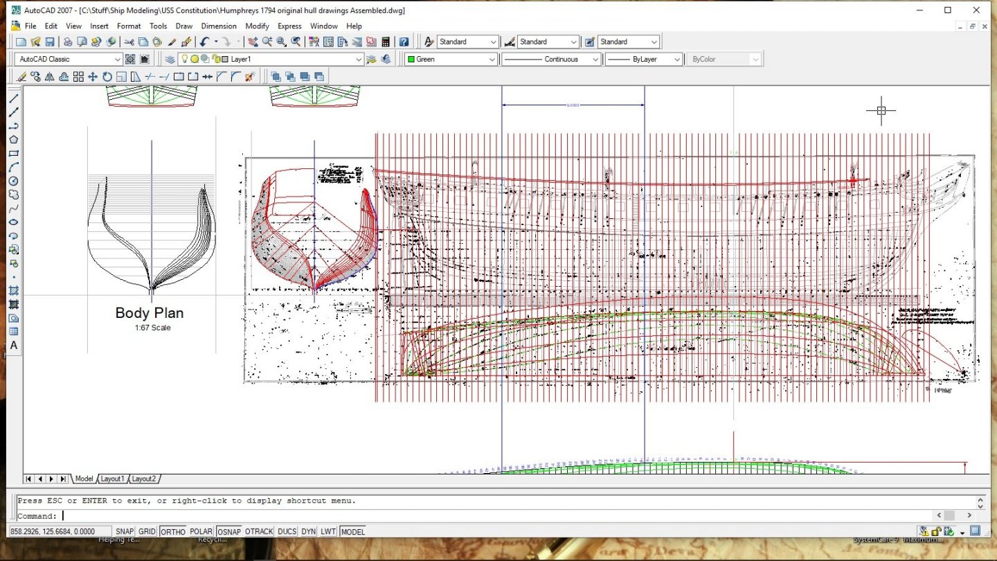
Has anyone reading this actually seen Humphreys original draft, in person? I'm wondering if 'time' and mishandling of the original drawing is the culprit behind the blurred and lackluster details... or is the problem simply due to simple photographs being turned into .PDF files? I've always hated working with .PDF's when true accuracy is needed. This bugs me. I could do the full build, however. I'd have to make quite a few 'generic' mid-ship frames, over-sized, and later fair them out, by eyeball, in accordance with the lines created via the known frame shapes. Would it look good? Sure it would, albeit. It would also be an artists conception. I doubt that anyone would know the difference, should I do such a thing, but 'I' would know!
-
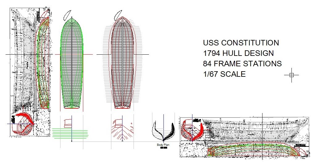
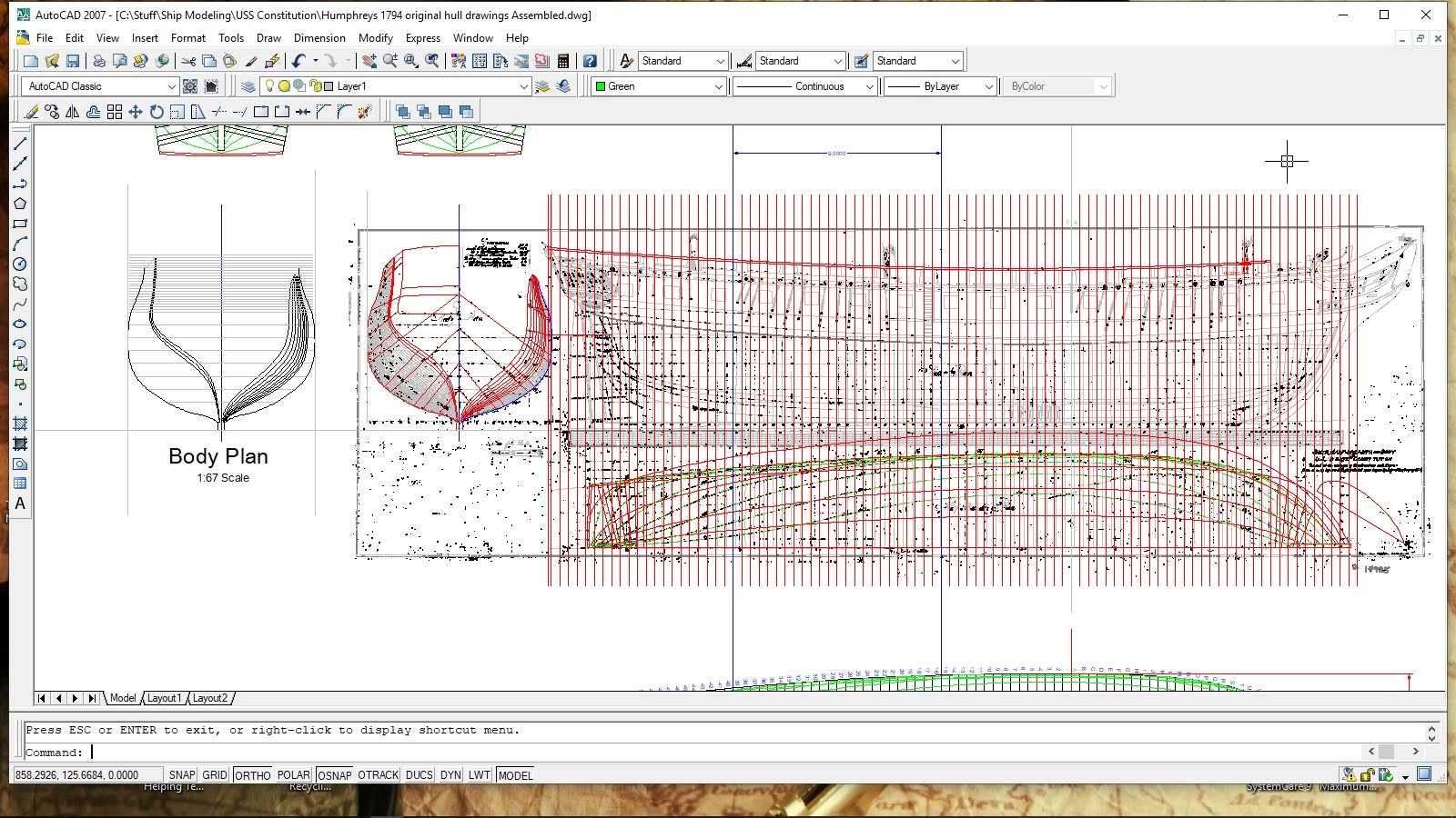
I thought that I was "good to go" and ready to start lofting frames, however. That turned out to be a premature statement. I've been having way too much trouble trying to pull out accurate/usable details from the .PDF photocopy of Humphreys drawing. Forward section "G" through aft section "15" are basically nothing but one big blur. I can't accurately loft any frame lines within this region. It would be a guessing game. Luckily, frames "16" through "39" are clear and doable. This is also a great location for an interesting sectional build. That being said... This is officially going to become a 9" long, 1/67 'sectional' build of the Connie. I'm tired of chasing my tail to no avail. I want to finally make some good progress!😒
The lines, in blue, with the 9" dimension is my targeted section.
-
23 minutes ago, reklein said:
I really like these kinds of posts.Very informative and interesting to see how folks solve their problems.
I'm glad that you liked this. I'm not an expert on 'any' particular subject, by any means! I'm just one of those types who likes to tinker with things in hopes of 'building the better mousetrap'. If something works, "It simply works"... if it doesn't work... I'll find something 'else' to tinker with in hopes of realizing better results.
- Duanelaker, davyboy, mtaylor and 2 others
-
5
-
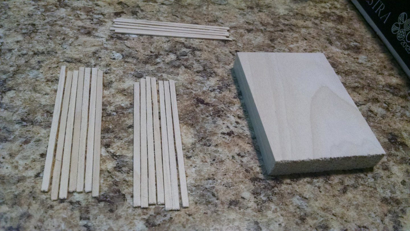
Push sticks were certainly used, however. That was not the problem. The problem was that I didn't use wide enough, nor 'long' enough 'resawn' pieces of wood to cut my planks from. Didn't feel like driving to my place of employment and using the bandsaw to resaw longer/wider blanks. I used this little bugger to 'resaw' my very short 1/2" thick wood stock into .085" thick X .500" wide wafers. I then reset my fence to cut .125" wide planks from those .085" wafers that were only .500" wide. Two push-sticks didn't work. The material just kept trying to scew off of the fence and also rise up, off of the blade. I couldn't effectively control the small pieces with push-sticks. I had to reluctantly hold the material down, with one hand, while using a small push stick to 'push' the actual plank, that was being cut, through the blade and effectively out the rear of the blade. I had to use my fingers to keep those 1/2" wide planks held tight against the fence, while also holding that narrow wafer down to the table. Not very comfortable having my fingers that close to the blade. I also tried pinning the narrow material down, with a piece of wood, to keep my fingers away, however. That didn't work very well either. Couldn't get any sure footing/traction on the narrow piece being cut. Long story short... Had to use my fingers!😮 That being said. I 'DID' go to the shop and resaw some yellow-heart wood into 3" wide X .125" thick X 12" long slabs. I brought those slabs back home and 'EASILY' ran them through this little saw to produce some nice .085" thick X .125" wide planks. No white knuckles were developed, this time. Apparently, size 'does' matter, sometimes!😕
This should be enough yellow-heart planks to complete the black/yellow color scheme for this small sectional model. The black 'ebony' was previously cut, at work, via the bandsaw. That's why you don't see any cut ebony planks in the photo. This is about a tiny, cheap Chinese saw. I didn't cut the ebony on this tiny saw!
... Anyway. I think that this thing might be a good option for someone on a budget and/or those who are just looking to get started within reasonable means. You can even tilt the bed, for beveled cuts, by simply slipping thin shims between the bed support and the table height adjustment nut. I did that to create a slight bevel in the yellow-heart planks shown in the photo. I used a piece of standard thickness printer paper for 'my' shim material. That was all it took to get nice tight joints between the planks. Would I recommend this? Yes, I actually think I would! I believe it is a good value for the money, albeit. You'll need to keep the thickness of your wood to around a maximum of half inch, subject to density/species of wood. That's about all it can handle. I wouldn't try 1/2" of thickness in any really hard/dense woods. Doubt it could handle it. You'll also need to be a bit creative in how you setup/use this saw. It's basically nothing but a motor that spins a saw blade. No fancy bells/whistles included. Accuracy and effective use is going to be up to 'you' and the limits of your own personal imagination! I'll actually give it two thumbs up, for the cheap, simple piece of equipment that it is!
-
Well... the silly little thing actually works pretty good, for what it is! I cut some 1/2" poplar to the thickness of my desired planks, then cut the width of the planks. I just clamped a steel flat bar down to the table for a fence, and to handle the really short pieces while they were being cut, well. Not so sure that I should share 'that' info. It was rather dangerous and I don't want to encourage any potential accidents. I'd have used a longer piece of lumber, but didn't have any as long as I'd like to have used. These short planks are for a sectional model and they are plenty long for 'that' project. I have no doubts that this cheap little saw will work fairly well on cutting longer, wider, thin strips for planking purposes. Don't know how long the motor will hold up, but seeing how's it doesn't seem to bog down while cutting, I'm hoping it will hold up for a while. "We'll see." 😶
- mtaylor, stuglo, Jorge Diaz O and 1 other
-
4
-
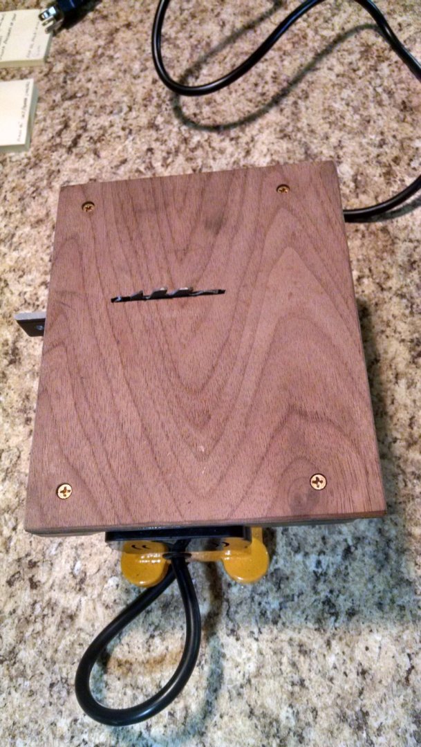
Sorry. No Blade height adjustment. The motor and blade are fixed. You must raise/lower the table, itself, to adjust the cutting depth. The table is held in position via a single knob/screw. Far from ideal, but good enough to serve its purpose, for now. It was fairly easy and quite safe to walk the table down. I simply snugged the knob just tight enough to hold the table steady when I let go, but also loose enough to move the table when needed. The worst part of the operation was wondering when that darned blade was 'FINALLY' going to poke through the top!😐

-
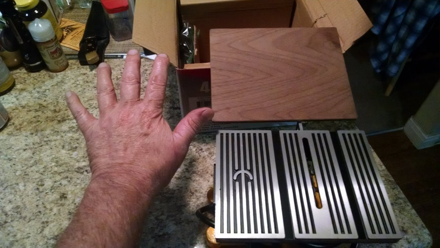
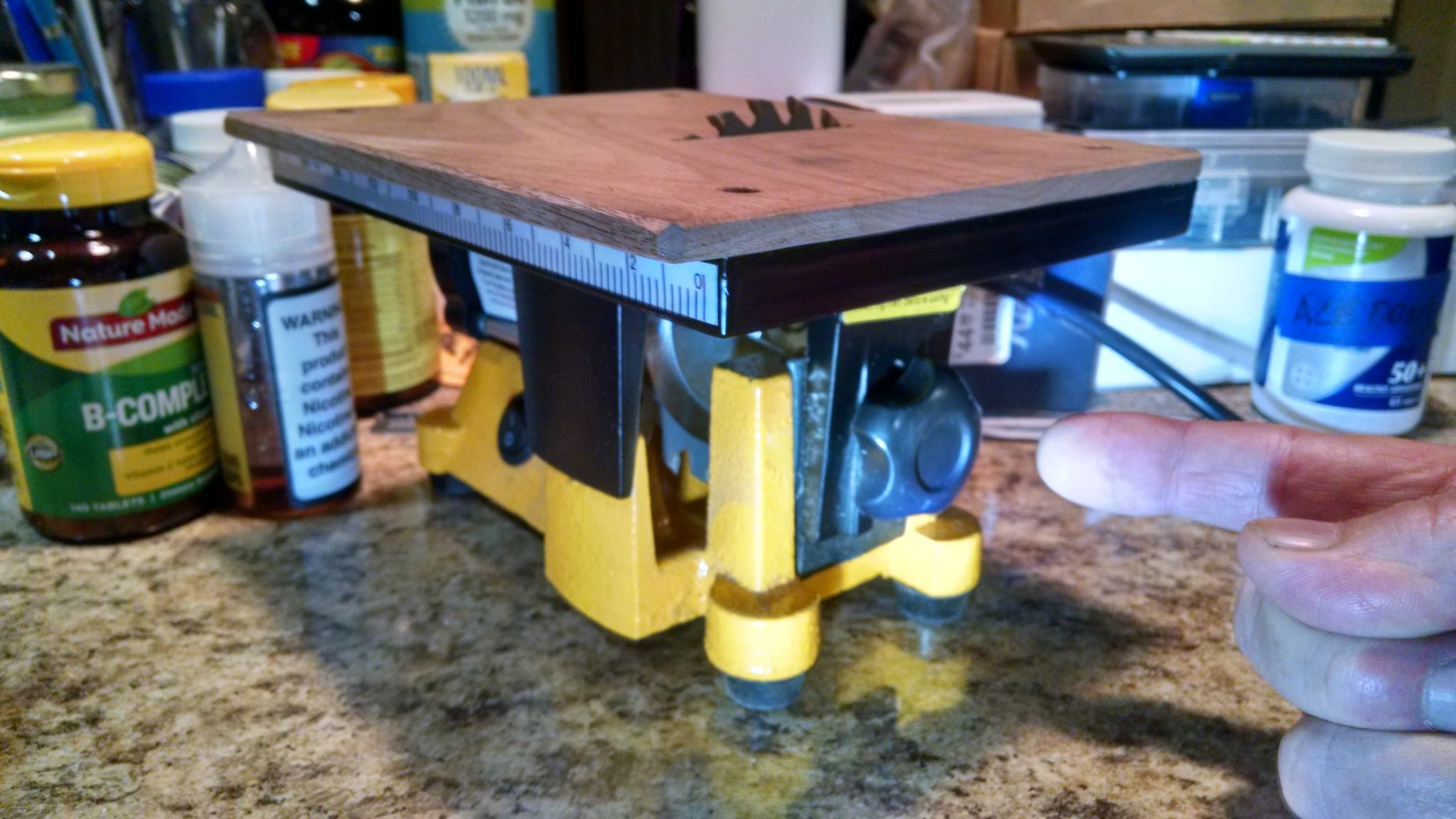
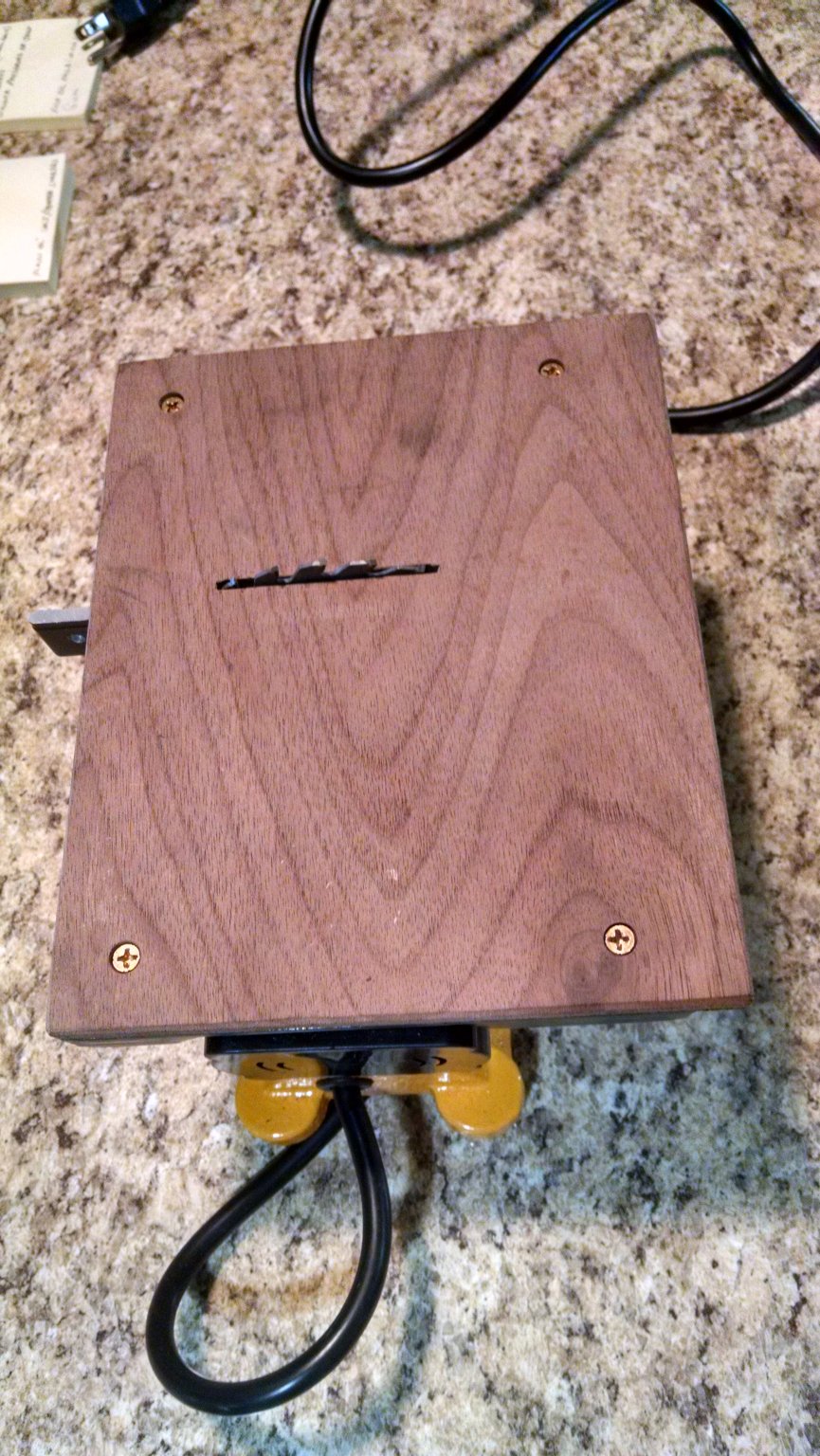
Found enough time to get the table 'ready for action' this afternoon. After drilling, tapping, countersinking and screwing the 1/4" walnut top down to the aluminum table... I remounted the table to the saw and cut the slot into the walnut top by simply 'walking' the top down, onto the spinning blade, rocking it back and forth until the blade slot was complete. It took about five minutes to accomplish this task. I couldn't get too 'greedy' in my cutting without bogging the blade down, but hey. That blade was cutting through quite a bit of material before it finally emerged through the top of the 1/4" thick walnut. I'd say that this operation gave the motor a rather good workout. Once all was said and done, the motor still felt quite cool to the touch and I didn't smell any lacquer burning on the winding's. "So far so good!" I'll next set up a simple, make-shift fence... and actually try to cut some 1/2" lumber into planks.
-
Just ran into a 'SNAG' with Malco Saw. Their minimum 'online' order is $25.00. The blade that I want is $24.88. Online checkout requires me to order 'TWO' blades in order to meet the minimum, plus $17.25 for UPS ground shipping... for a total of $67.01. That kinda defeats the 'cheap' thing that I was seeking. I'll give them a call, tomorrow, and see if I can just order one blade and have it sent via regular USPS mail.
- Canute, mtaylor and Captain Poison
-
3
-
17 hours ago, Roger Pellett said:
Isn’t 12.8mm, 1/2in? Then a blade with a 1/2in arbor hole readily available here in the US should fit.
Roger
Yep, but I was struggling to find a source that sold them. I've never before used a 4" table saw. New territory for 'me'. Thanks to Mr. Taylor... "Problem solved!"
-
19 hours ago, Bob Blarney said:
It looks like you've thought this through. Until you put a decent sharp blade on it, I'm not sure you'll have an assessment of the runout/slop in the arbor bearings. One thing you could do that would probably help is to make/buy some stiffener-stabilizers to place on the arbor beside the blade. Another thing that you might do instead of screwing down some perfectly good walnut to the table, would be to put down a thin layer of baltic birch with plastic laminate (or just acrylic window glazing) on top for a smooth surface. A sled would improve performance too, and maybe a better fence is a good idea.
Oh, and if those miter slots are 3/4" wide, then you might be interested to know that US pennies are exactly 3/4" in diameter. I've glued them to sticks used as runners for sleds on my full-sized table saw.
Believe it or not... this thing actually came with some really decent 'wafer' like stabilizers sandwiched to both sides of the blade. I was really surprised to see that! Not going to go crazy with a sled, fence, etc. here. That would be like putting $2K of wheels and a $4k stereo system in an old 'Yugo'! I'm just having some fun with this thing to see what it can easily and 'cheaply' do. Might be a worthy endeavor that will help some folks out who's budgets are rather limited. I remember living such days, myself!
-
17 hours ago, mtaylor said:
Before you get into re-machining your arbor... have a look here: https://www.malcosaw.com/ I think you'll want the "cutting blades".
"WooHoo!" "JACKPOT!" Many thanks for tossing me this bone, Mark! Nope, no machining of the arbor will be required, now! Great lead, I'm placing an order, NOW! 😊
-
Can 'I' live without a Byrnes table saw? "Perhaps I can... perhaps I can't!" That's a tough one. I'm of the mindset that you 'Always Get What You Pay For', albeit. I'm also a 'tinkerer' who loves to mess with cheap Chinese
trashproducts and modify them to a point where they can actually do the things that theirmisleadingconvincing advertisements wouldfalselyboldly lead one to believe, in expectations, as to the truewasteworth,slopquality... andfaultsdependability of what's actually beingpeddledadvertised. If you have the means, you actually 'can' turn a lot of that cheap Chinesejunkstuff into somewhat good and useful pieces of equipment. It's really not that hard to do. What follows are photo's of a mini table saw that I'm going to do the BASF thing to. Just like BASF... I don't make the Chinese trash that people buy. I make the Chinese trash that people buy, BETTER! 😉For starters. This thing cost me only $50 bucks on Amazon. It's not a powerhouse... for light duty only. I'll be using it to cut already thin slabs of resawn and thickness planed woods into planks. It's not a fast one, either. The no-load RPM is only 4,500rpm, at 110 volts with a draw of only 90 watts. Definitely not the strongest bull in the arena... but powerful enough to effectively tackle the light duty tasks that I want it to do.
Upon un-boxing it, I was surprised at the weight for its size. It's actually quite heavy! That's a good thing. It won't slide all over the place while being used. I turned it on and it was amazingly quiet. No vibration, no problems there! "Impressive!" Now let's get down to the nitty-gritty, the things that need serious attention...;
1)... The motor was mounted well out of 'true' and the blade was running at about a 10 degree angle from a straight cutting orientation to the bed. No biggie. Had to remove the cover plate on the bottom, loosen the screws that secure the motor, then align the motor and tighten the screws.
2)... The blade was also hugging the side of the slot, in the bed, and had to be readjusted to the center of that slot. Loosened a screw, on the arbor that holds the blade, moved blade to its proper position then re-tightened screw.
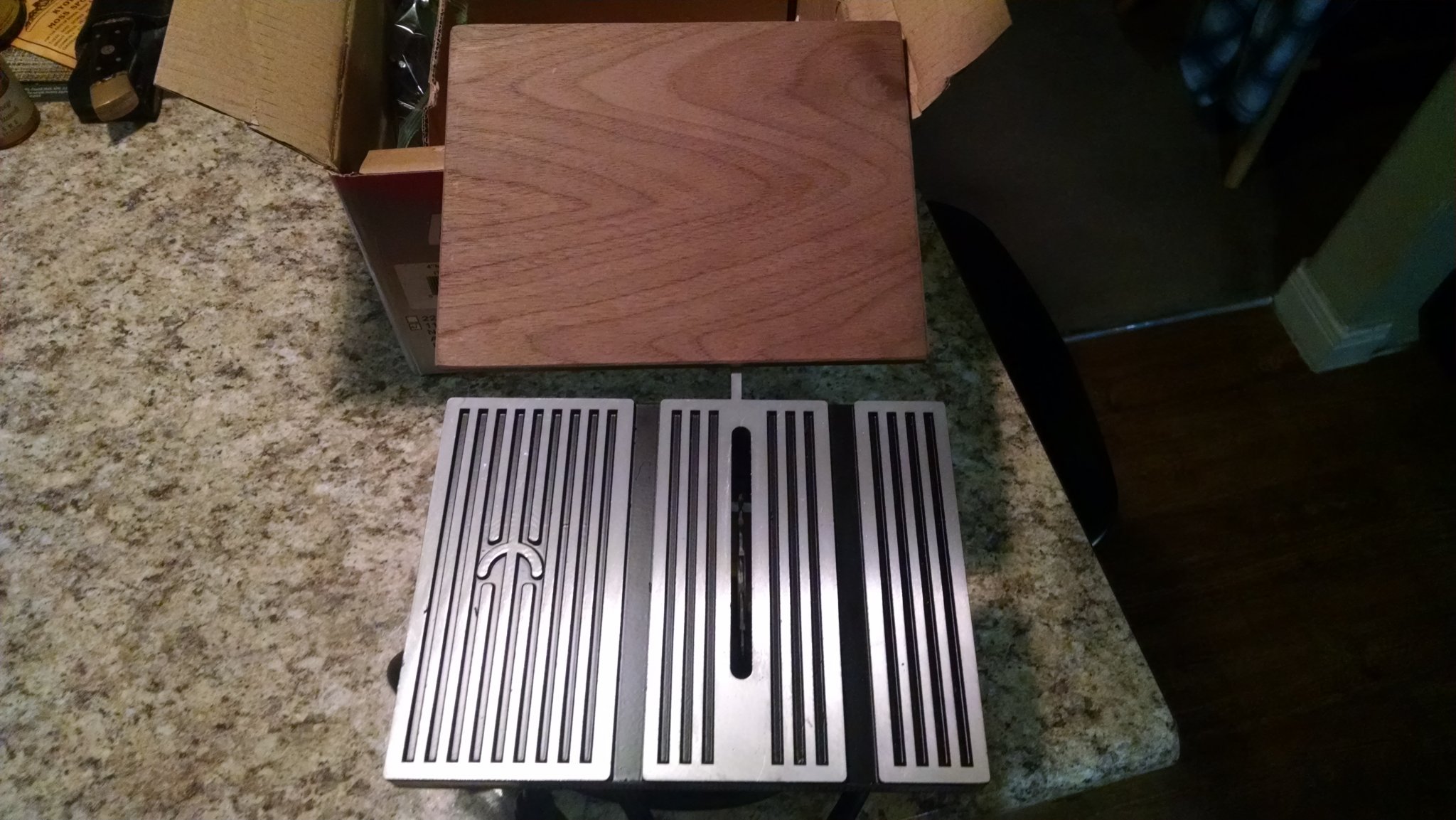
3)... The surface of the bed is incredibly rough. Not good at all! Sure, I could sand it down with fine grit paper, but have opted to skin it with a 1/4" slab of walnut, instead. I'll drill and tap the wood/bed to secure the walnut slab to the bed. I'd probably do this anyway, even if the bed was smooth!
4)... I also don't like the tooth count on the blade. It's a bit course. Quite course, to be exact. No biggie, however. The arbor is a really odd-ball size. 12.8mm (go figure... @#$!). I'll have to put the arbor in my lathe and turn it down to 11mm to fit an 11mm 40 tooth blade. I'll leave a step/shoulder at its original 12.8mm size, just in case. There's enough play in the arbor/shaft to allow me to shift the arbor to whatever step/blade I choose to use.
5)... Adjusting the bade depth is pretty hilarious/crude/sloppy. There's a knob/handnut that loosens and tightens the table to adjust the height. Very cheesy and sloppy. I probably won't even mess with this problem as it is simply not worth the time and effort to make it better, unless it causes the bed to sit unlevel to the blade and causes unwanted crooked/beveled cuts. If it is crooked, that could actually work in my favor and save some time sanding bevels on my planks, but I'm not gonna count on that!
I'll likely purchase a Byrnes saw, after Xmas, but for now... I'm gonna play with this
piece of crapquality Chinese saw and see what kind of mileage I can actually pull out of it... after my modifications, of course!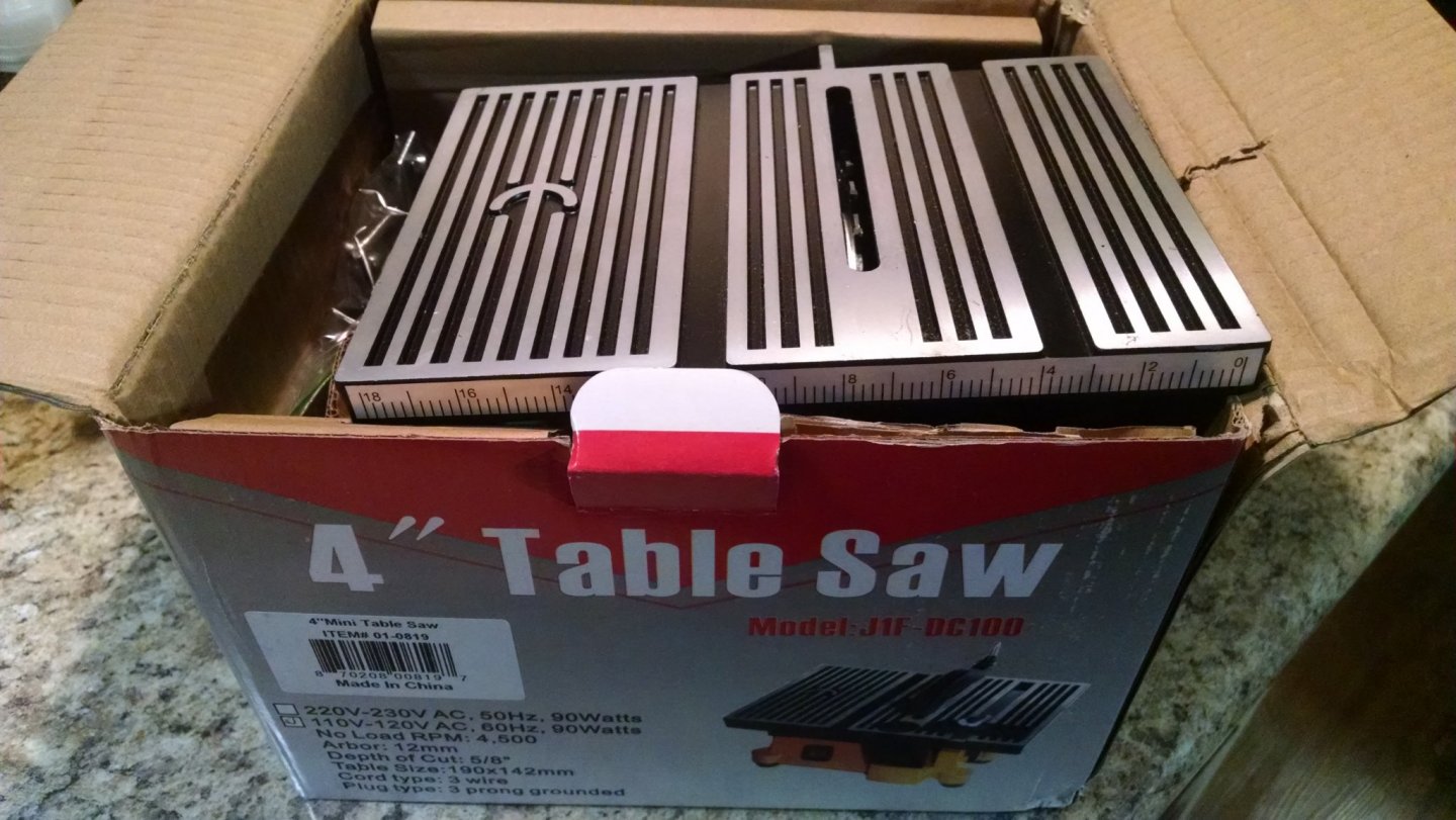

- kuya, EricWilliamMarshall, Moab and 1 other
-
4
-
-
Hey Mark! It's really funny that you mention that. I actually considered doing 'exactly' what you described, however. The manner in which this kitted model's 'framing' takes its form is a bit problematic, as you can see in the photo below. I'd have to either do some seriously precise band-sawing, routing, etc. to achieve the 'appearance' of 'frames', on the non-planked side of the hull. Could I pull such a thing off? Yeah, probably, 'maybe'... 'BUT' (you know what 'but' means, LOL). I didn't think that the required time to do such a tedious thing would justify the end result of an already questionable model. I also didn't want to risk an "Ah Slip" and potentially ruin a lot of precision, tedious cutting, with one little mishap towards the very end (Murphey's Law). What can I say? I 'chickened-out' and chose to simply follow the path of least resistance... and decided to plank the darned thing, entirely. I do like the way that you think! You'll see such 'like' thoughts, in work, in the near future! 😉
-
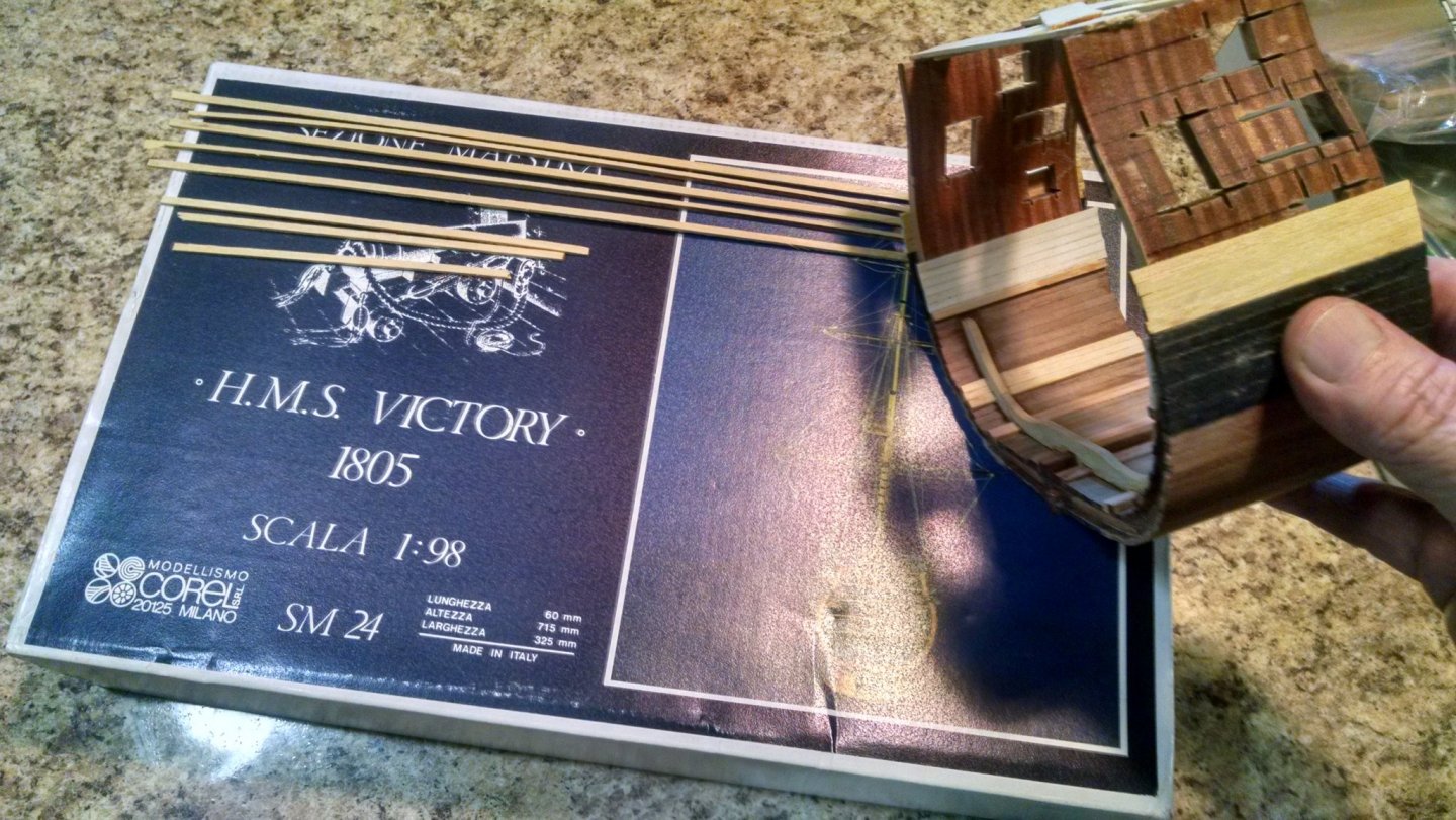
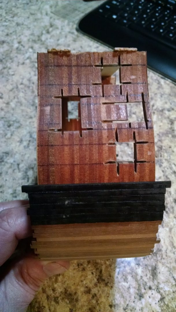
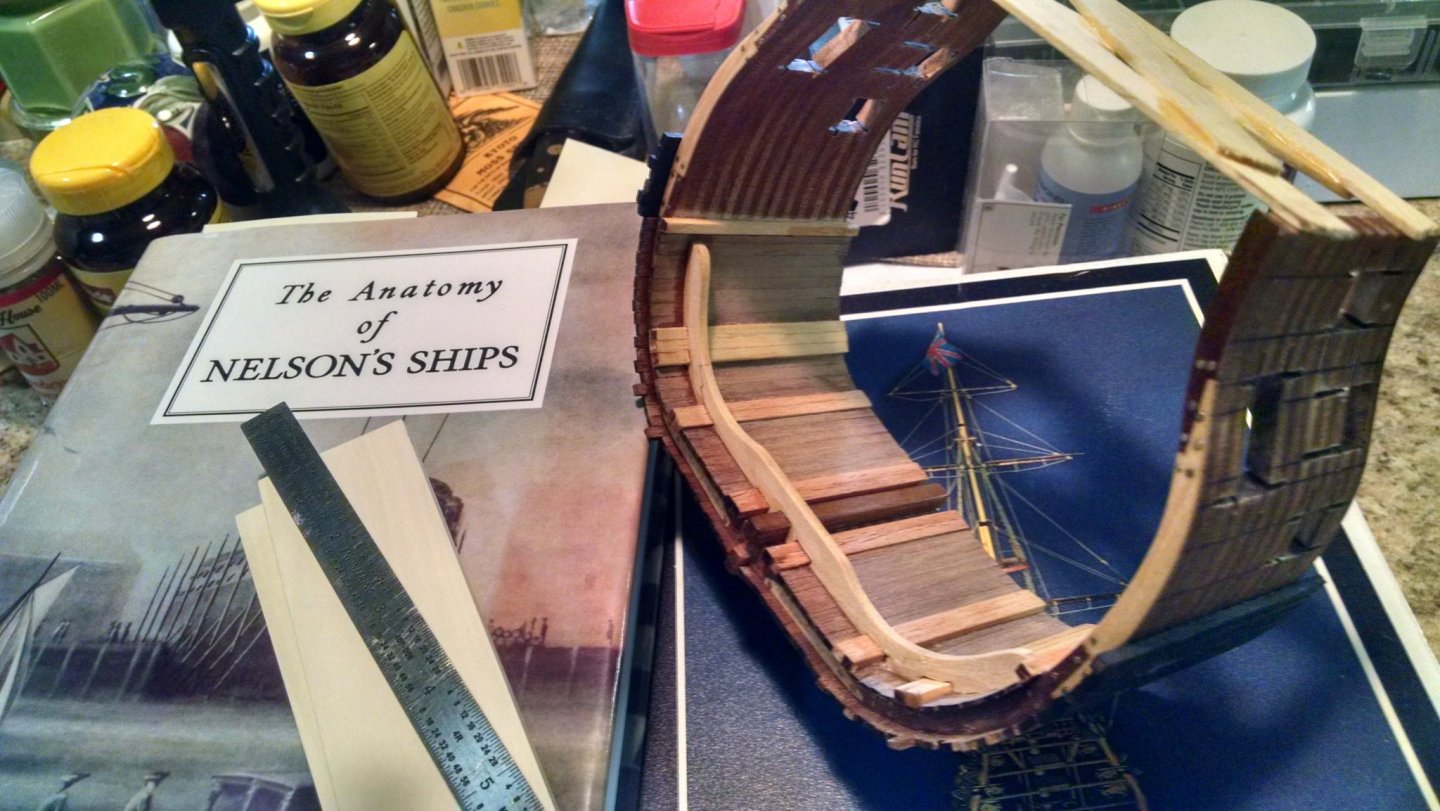
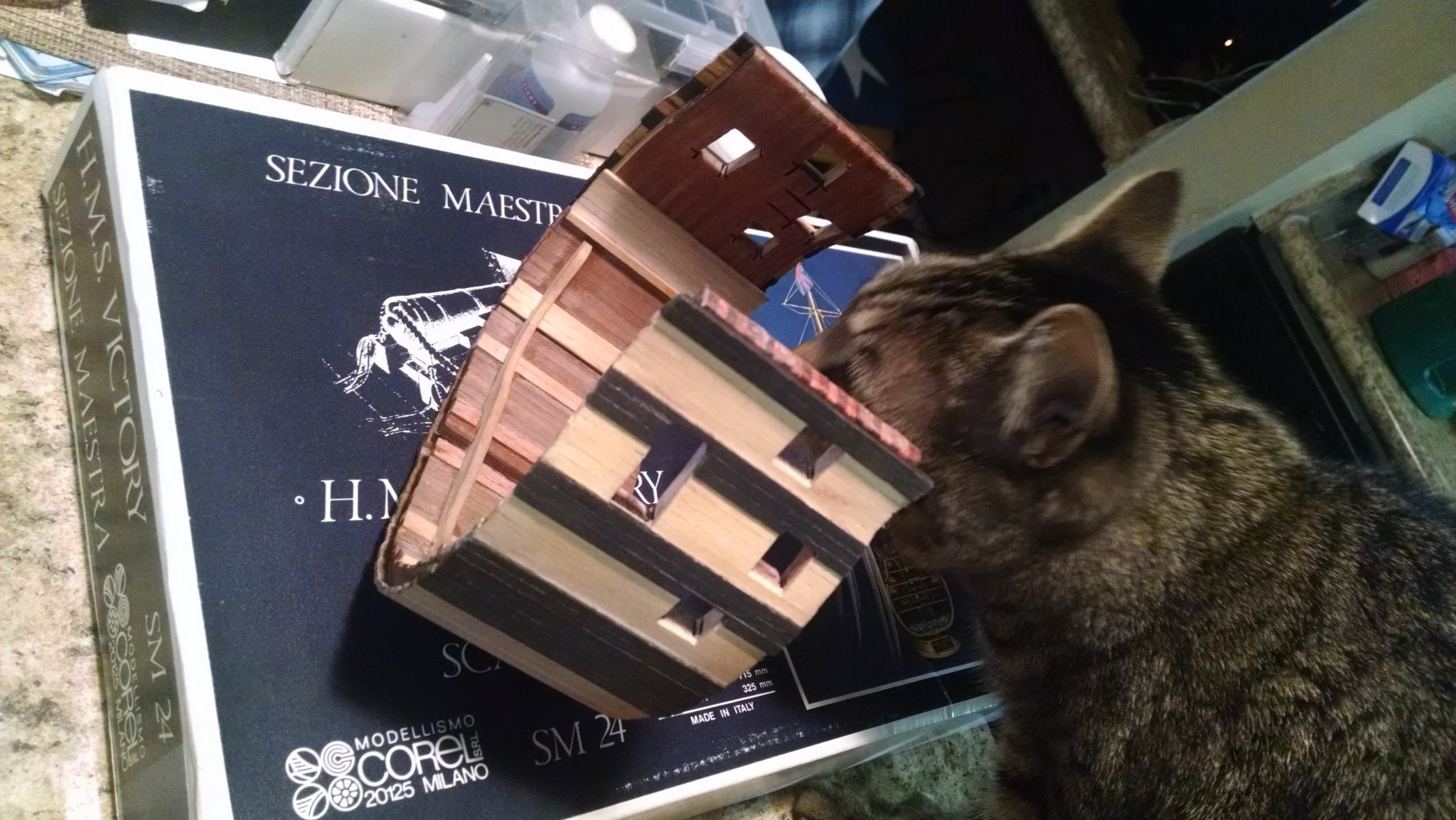
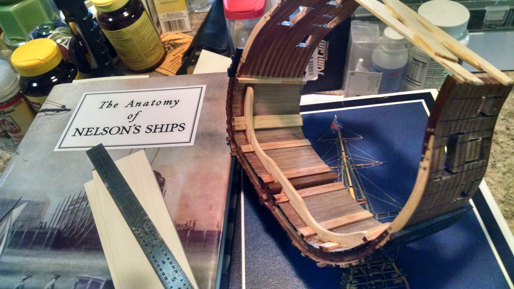
While taking a needful 'constitution', away from my actual USS Constitution hull drawing project... I've gone back to working on a Corel cross section kit that I am 'bashing'. I cut all of the pieces, for all four of the riders, (16 small pieces total), a couple weeks ago, while taking my first break from the re-construction process of Humphrey's 1794 drawings of the Connie (lots of breaks will 'surely' be required during the course of 'that' project). I've only filed and fitted the pieces for the one single rider shown below (3 small pieces). I won't mess with filing and fitting the remaining 13 pieces required to complete the other three riders until I get past a newly discovered dilemma, of sorts. As you all know, Corel's kit is quite lacking in historically accurate details. That's where my desires for 'bashing' come in. I followed the kit instructions, 'blindly', prior to purchasing Longridge's book. Luckily, I did not go so far into the building process as to totally build it wrong and turn it into nothing but a nice looking shelf ornament. There's still a bit of hope for it, at this stage. While I can't make it 'proper'... I 'CAN' make it much better than it 'would-have' otherwise turned out had I simply built the kit as instructed! That being said. The internal planking "is what it is', to this point. I can't take that back, however. I 'CAN' proceed in a more historically accurate manner. That's what I am doing, however. I'm running into problems, already, with the riders. If I stick to historical accuracy and build it properly, the riders going up to the 'Gun-Deck' will obscure the visible profile of the shorter riders that stop just below the Orlop deck! "Hmm, what to do?" In order to show the craftsmanship of 'both' riders construction... I'd need to whittle the girth of the gun-deck rider down a bit in order to also show the profile of the lower riders... unless I wanted to swap positions of those two riders, which would be even more inaccurate than simply thinning down one of those riders, for viewing purposes. I can't see putting a lot of time into making precise pieces, and tight joints, that will not be seen without the use of a mirror and a flashlight. I'm also not too thrilled with intentionally deviating from true reality simply for the purpose of aesthetics and presentation. This is truly a dilemma. I'll need to weigh things in the ol' balance and decide which procedure will ultimately become deemed the 'lesser' of these two evils. In the mean time... I'm cutting exterior planks from Ebony to mimic the black paint on the outside of the hull, cutting white holly to mimic white paint on the interior planking, supports, etc., ... and waiting on some yellow-heart wood to arrive to thus mimic the yellow paint used between the black painted stripes on the exterior of the hull. I don't want to paint anything. I want to use natural wood colors that can somewhat 'simulate' the true colors to a respectable degree. Painting beautiful wood is a major sin in 'my' book... kinda like cooking chili with beans and sugar and then trying to pass it off as authentic TEXAS chili. I might actually be able to get away with simulating various colors of wood, via natural wood colors/shades, however. Cooking authentic Texas chili with beans and sugar also included in the pot? "That's a mandatory 'HANGING OFFENSE', for 'dang' sure!" 😧
- BLACK VIKING and mtaylor
-
2
-
21 hours ago, Roger Pellett said:
I believe that the curve from bow to stern and extending outside of the half breadths is one of the two diagonals shown on the body plan.
"I concur!" I'm just not used to seeing outboard diagonals take such a curious form. Makes me wonder if I am looking at something totally unfamiliar to me (which still might be the case). I say this because that drastic curve blends in quite well with the aft most form of the stern, but not so well/smooth towards the bow. Curious curves. Perhaps I'm just having a bit of difficulty in mentally visualizing those lines in a 3D frame of mind. You'll notice that I'm laying out my drawing templates in a rather curious manner. There's a method behind my madness. I'm separating the typical body plan from the diagonal plan. I'll be drawing these two separate plans in different layers so that I can lay these drawing layers atop one anther... and also compare them to the 'diagonal' lines depicted, for proof. I'll obviously need to start with the 'Cant' frames, as this is where the proof will be revealed in the greatest of detail. I'm hoping that my process of drawing layers, in this manner, will open up a third 'eye' in my currently lacking 2D mind... thus giving me a better view/understanding of what I'm truly looking at.
-
I've successfully cleaned up some of the .PDF file lines, and reconstructed enough of the smudged details, on that drawing, to finally begin lofting some extremely accurate frames. Due to my desired scale vs. readily available materials... this design will actually have 5 additional frame locations as compared to the original count. This won't affect anything other than adding a tad bit more work. 79 frame locations (original) vs. my 84 frame configuration... "hmm?" With that many frames to loft and fabricate, "who cares about five more frames?" To stick with my desired scale, the frames would have needed to be .3989" thick, for original design. That's too oddball a dimension, so I opted for .375" which works out great! Standard thickness of materials can be used to construct the frames without a lot of waste via thickness planing of much heavier material. It's an acceptable compromise.
Getting to this point has been a slower 'go' than I had anticipated, and also an exercise in frustration, to say the least... but it's also a very 'necessary evil' in my strife for historically accurate lines. Had I better drawings to work with, I'd surely be well beyond this stage by now. Working from a .PDF photocopy of a 'not so pristine' drawing that is 225 years old adds a whole new level of difficulty to the project! That's okay. The end result will be well worth the preliminary efforts required!
Next up will be the individual frames, one at a time. While I will know the exterior shape of those frames, I now need to come up with the 'internal' geometry and thickness(s) of those frames. More research will be involved, of course, but I can do that 'after' lofting the exterior geometry of the frames.
- Gregory, chris watton and mtaylor
-
3
-
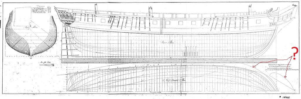
I posted a question about some curious drawing features, shown in Humphrey's original drawing, in a another venue of this forum dealing with plans, etc.. I'm asking the same question, here, to double my odds of getting a good answer. I've noted, in red, two curious features/lines on the half-breadth section of this drawing that leave me scratching my head. There's actually a few more similar lines shown on the original drawing, once I zoom in on things, but if these two obvious features can be explained... I'll know how to interpret the rest. What do the lines that run well 'outside' of the hull's actual design represent? Also, what is that 'curious' looking geometric feature that resembles the cross-section of an extremely high lift/low speed glider airfoil? I'm doubting that these things are truly necessary for my accurate reconstruction of the hull, for this model ship, however. I'd really like to know just what they represent and why they were important enough to be included on Humphrey's 1794 drawing. Someone will know what these lines/things represent. If you are that person, please chime in and enlighten me!
-
I've not posted any updated progress on this build, but bear with me. "It's coming!"
Just because I've not posted anything doesn't mean that I'm not actively working on it! As soon as I have something truly worth sharing... you folks will certainly be the first to see it! 😊
I've so far encountered numerous 'technical difficulties' in my reconstruction of the original 1794 images, of the USS Constitution's lines, via the .PDF files that I am forced to work with. I first have to convert those .PDF's into something that CAD can actually read. It's an easy process, however. PDF's aren't very precise, therefor... certain details, features, etc. tend to get lost and sometimes confused/truncated in the conversion process of such drawings. In reconstructing the drawings, for accuracy, I need to effectively reconstruct portions of my 're-constructions', due to those curious/lost details... if 'that' makes any sense! The mid ship section of the 'Body Plan', required for the accurate forming/modeling of the shapes required for those mid ship frames has so far proven to be the worst offenders, via the loss of detail, via the conversion process... forcing me to also have to reconstruct the shear and half-breadth lines/plans for better proof and accuracy. That being said. I'm also running into the same issues of lost details and curious truncation with the shear and half-breadth views. "Aarghhh!" I'm now wondering if I will actually be able to pull this off, with the level of accuracy that I seek! "Damn the torpedo's... Full Speed Ahead!" I'm still gonna "Get 'er Done", albeit. It's obviously going to take quite a bit longer, on the ol' drawing board, than I initially expected the design stage of this build to take. I could cheat, but I won't. "That would be 'cheating!" I'm not going to cheat and take the easy way out, just to 'bang something out' and settle for hand-grenade, 'horseshoe', or commercial marketing accuracy. I'm going to split them curious hairs, scratch my head, do some math, drink a beer or few... and do my best to do 'er right!
Stay tuned... "The show will begin... shortly!"
- G.L., mtaylor and GrandpaPhil
-
3
-
Very interesting, Wefalck! Very interesting, indeed!! Enlighten me further! How would the ship's captain know 'exactly' how much ballast to take on... and how to properly distribute the various weights of those ballast materials in order to create desirable sailing conditions/situations for a particular cargo/journey, in various weather conditions, seas, etc.? Let's go to extremes on this one. Let's talk Tea Clippers. Their cargo would be rather light, as compared to heavier loads of other trade goods, thus requiring a great deal more ballast, to achieve proper 'weight and balance' for the upcoming voyage. Clipper ships were also the old world equivalent of modern day racing vessels, seeking speed, per se. That being said, they had to take this into consideration when loading ballast... as the lower a ship rides, in the water, the more 'upright' the ship will ride, thus maximizing the amount of energy that can be generated and effectively utilized by her sails (a ship laying over on her side bleeds off a great deal of energy, while also exposing more surface area, upon the dense water, via the hull, which creates added drag and slows the vessel down). Would a clipper ship captain, looking for speed, opt for a heavier ballast load thus achieving a more 'upright' attitude, riding lower in the water, or prefer a lighter load of ballast that would allow the ship to ride higher and also list more dramatically, in high winds, intentionally bleeding off a certain amount of energy? Either way, I see a lot of stress being imposed upon the masts and sails as well as drag upon the hull. Seems like a "Catch 22" to me, but I'm sure that was some sort of a happy medium, science, and/or general 'rule of thumb' involved with this. Interesting stuff!
Anyway... back to where my thoughts began with this reply. "How did the ships Captain determine how much ballast to take on, and how to properly distribute the weight?"
- mtaylor, thibaultron and Canute
-
3
-
With the sails furled, two problems arise. Number one... the sails would become semi-frozen, brittle and quite difficult to safely 'unfurle' without potentially causing damage to the fabric, should conditions improve enough for stowed sails to be needed. Number two... with the sails remaining full... the ship would be in constant motion, provided there were winds/breezes blowing. Those winds/breezes, and the full sails would keep the hull in motion, 'rocking' in the ice/water, and thus preventing its hull from becoming 'still' enough to become frozen solid into the ice cap thus becoming 'impossible' to break free, for movement, once conditions improved enough for forward travel to become possible, again.
Notice how the ship is listing to the starboard side. "Thar be a breeze coming from the port side!" Also note the water in the foreground of this photo. Note the attitude/deflection of the sails shown in that photo. Looks to me as though that the ship is intentionally being steered towards the foreground, where the water is... rocking port to starboard, via the winds... and slowly cracking the ice, to get there, a few inches at a time.
As for what those folks are doing outside of the ship... "who knows?" Perhaps they just got a touch of 'cabin-fever' and needed to go for a walk about! 😏


New Member from Sweden
in New member Introductions
Posted
"Howdy and welcome aboard, pardner!"