Bruma
-
Posts
179 -
Joined
-
Last visited
Content Type
Profiles
Forums
Gallery
Events
Everything posted by Bruma
-
 Kirill, this is really a masterpiece. A testament of what can be done with a humble plastic kit as a base and a ton of skills to upgrade it. Thank you for sharing!
- 228 replies
-
- 3
-

-
- spanish galleon
- lee
- (and 1 more)
-
No, not at all. I spread the modelspan on a big, glossy surface (the recycled box of my doughter's scooter has proven to be perfect). The glossy surface ensure an easy detaching of the modelspan once it's wet. Painting it on both side has been just a matter of time and patience. Once wet it is still quite strong. This medium is just wonderfull.
- 399 replies
-
- 7
-
-
- cutty sark
- revell
- (and 2 more)
-
Thank you, Rob. I know your masterpieces, and I'm honored to have you here as many other expert modelers who take the time to visit my humble Cutty Sark. I have had no luck with paper, I was not able to get the double curvature I was looking for. This is particularly true for the square sails. That's why I tested the modelspan.
- 399 replies
-
- 2
-
-
- cutty sark
- revell
- (and 2 more)
-
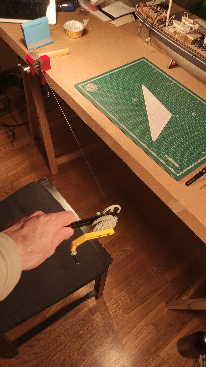
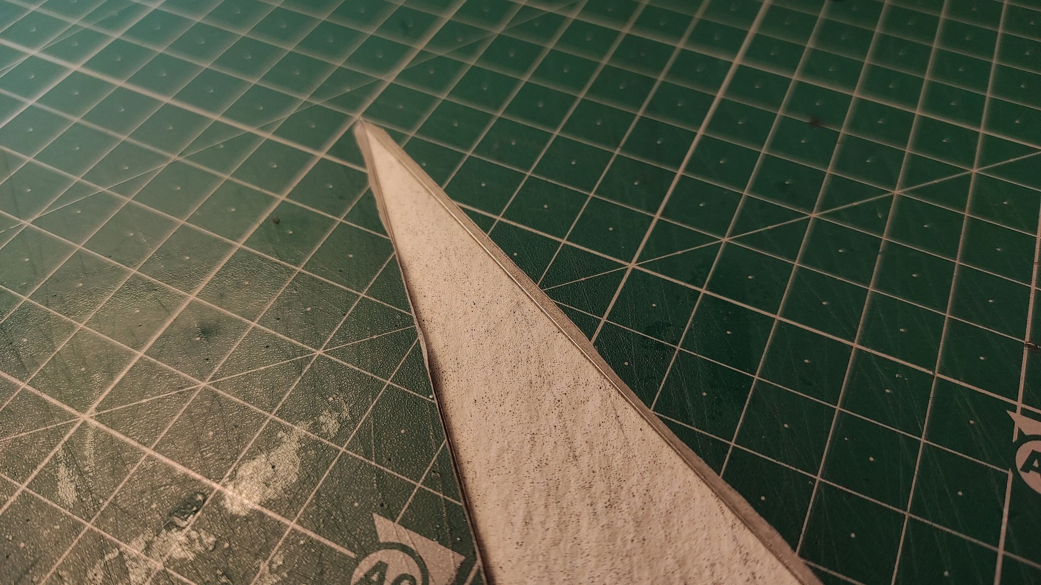
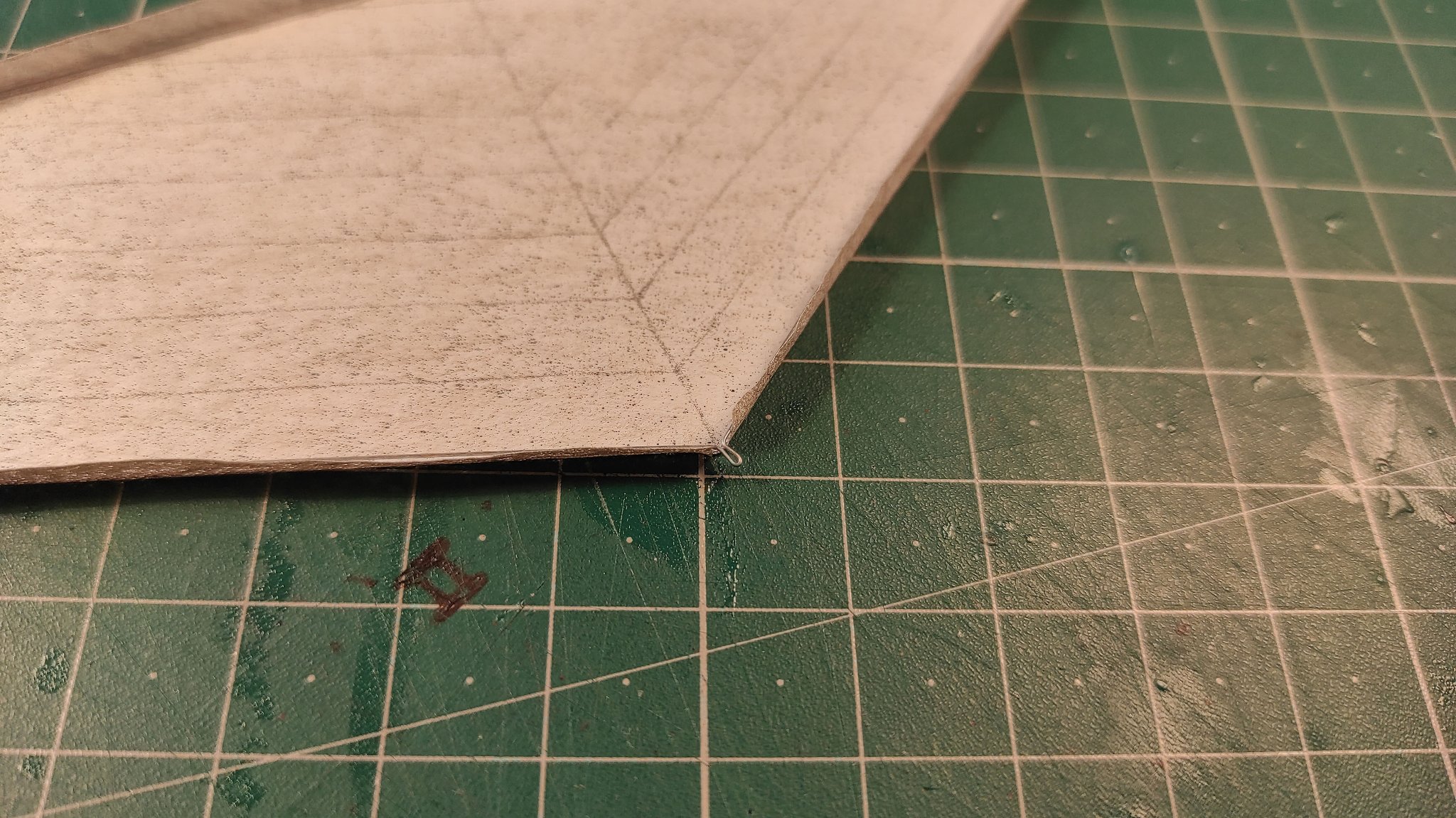
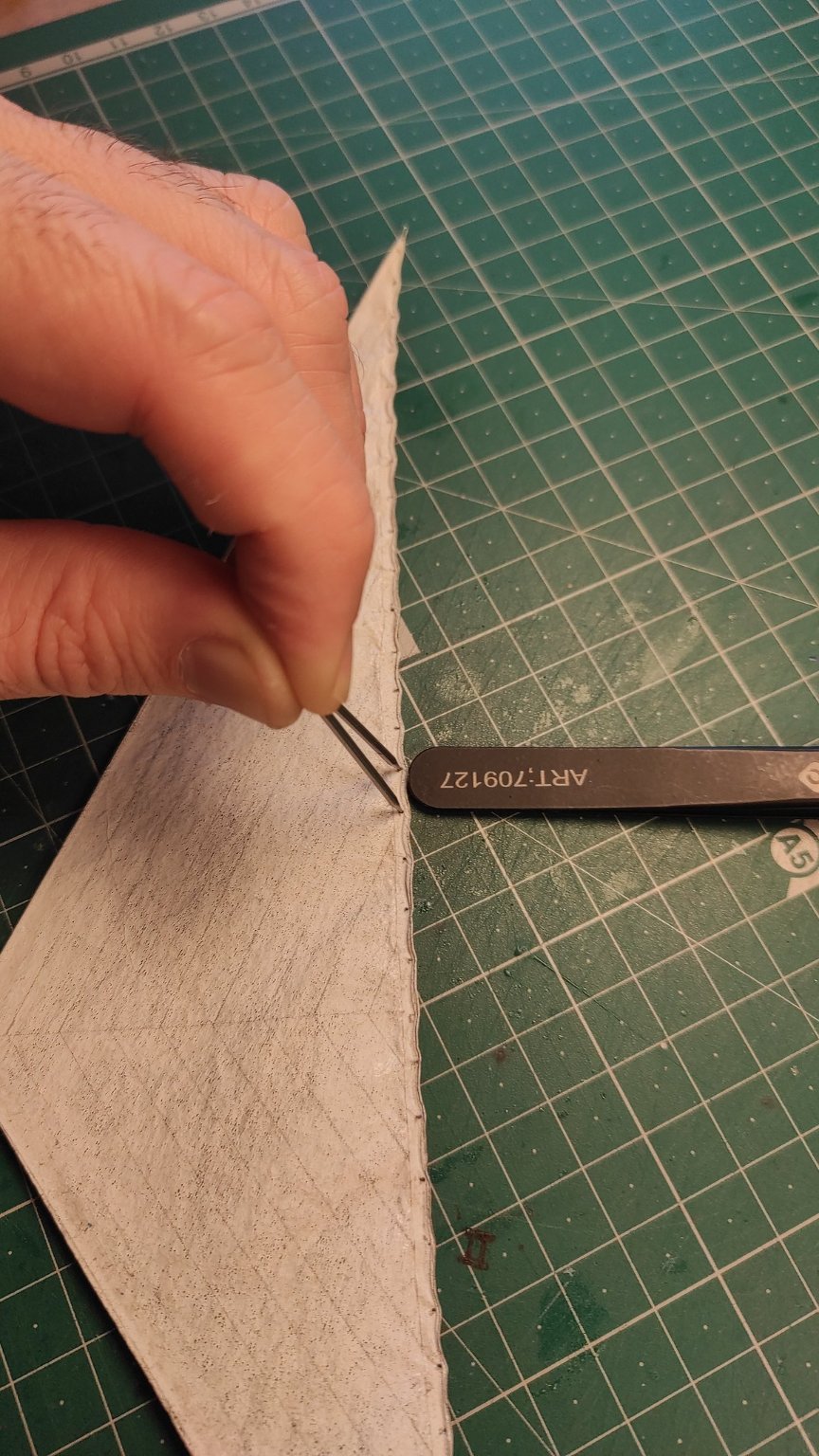
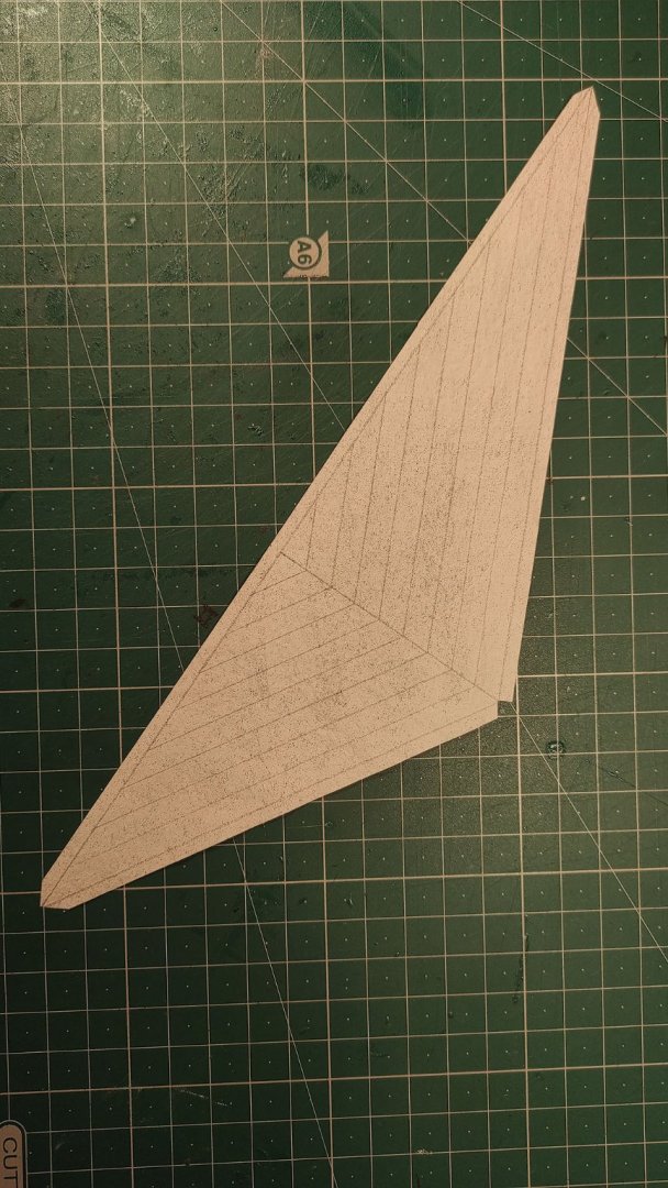
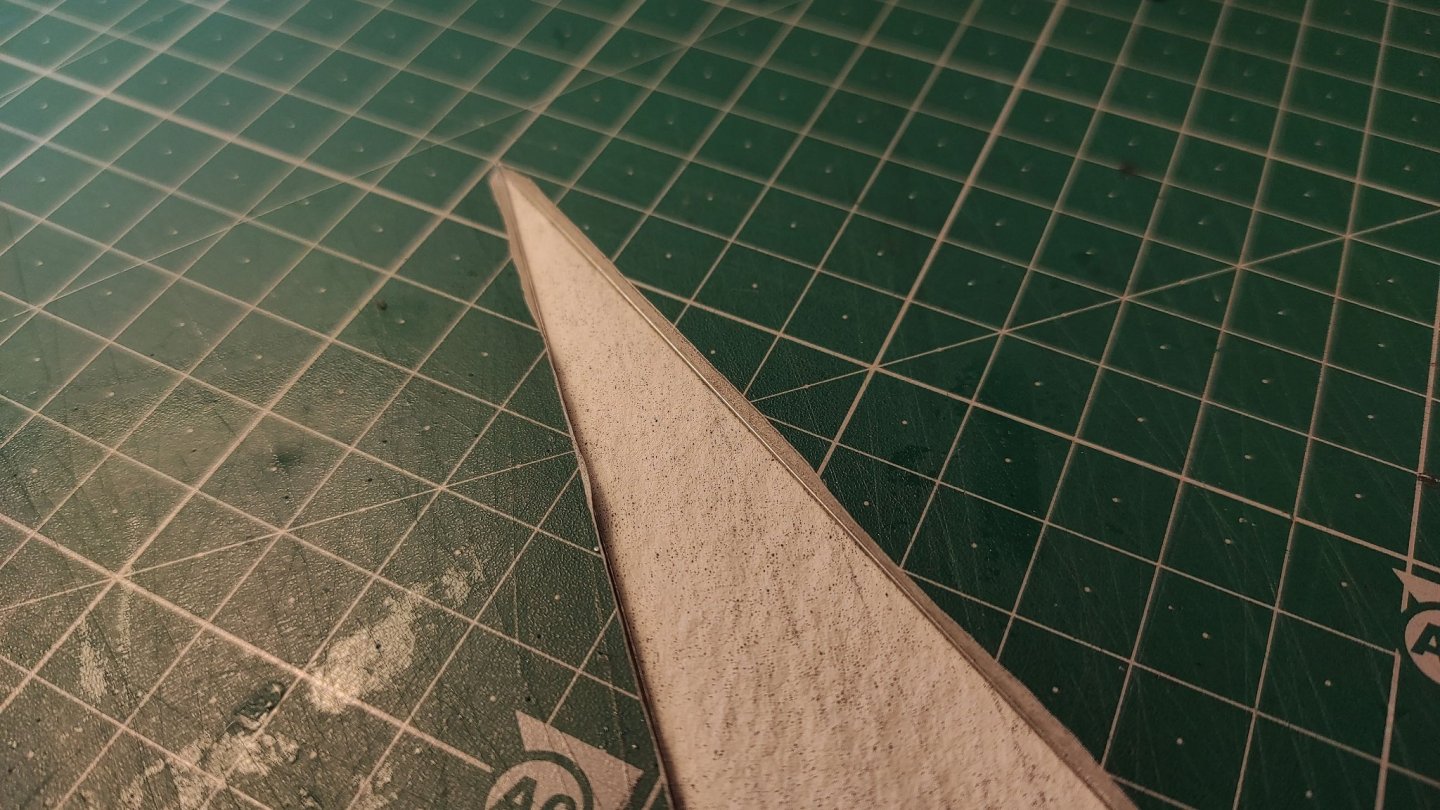
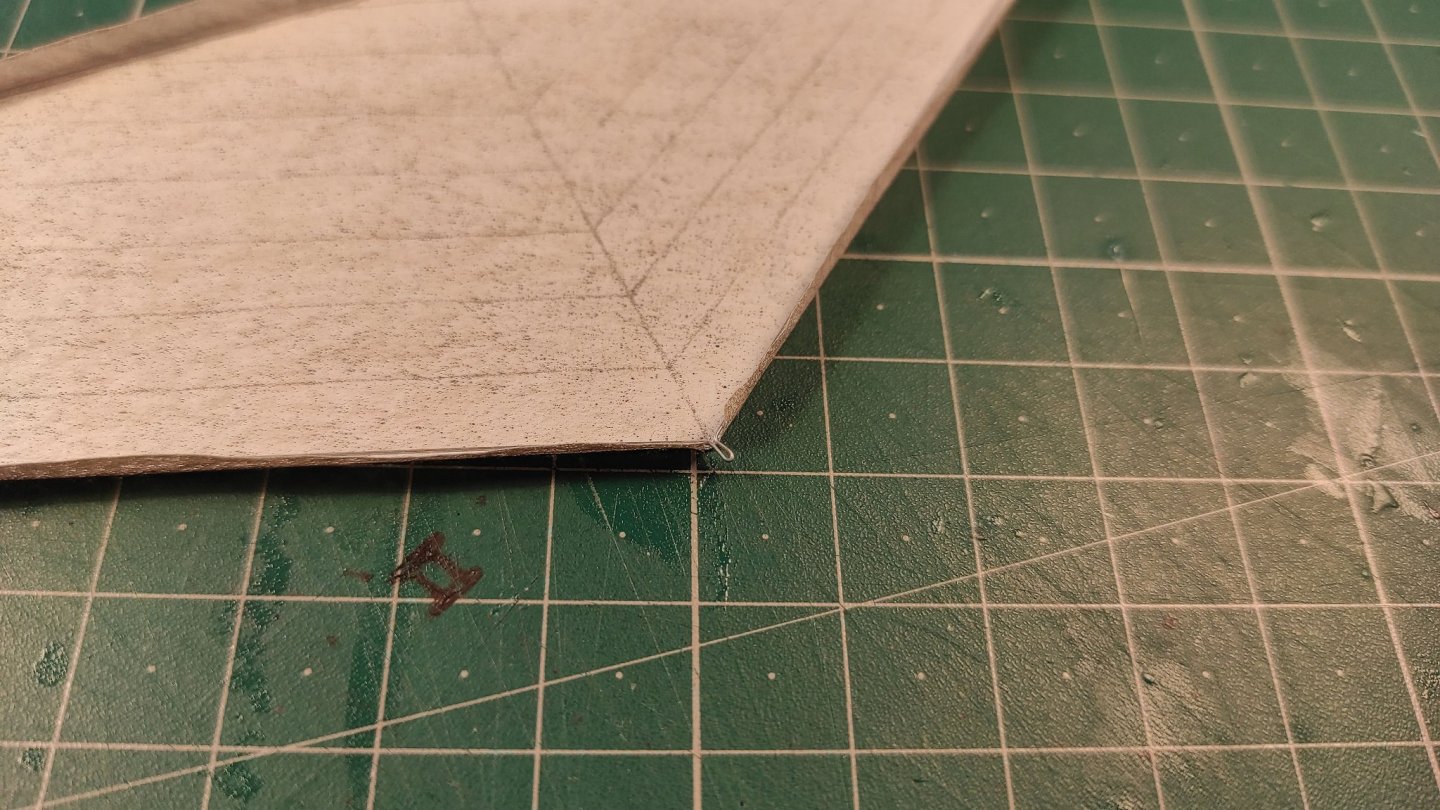
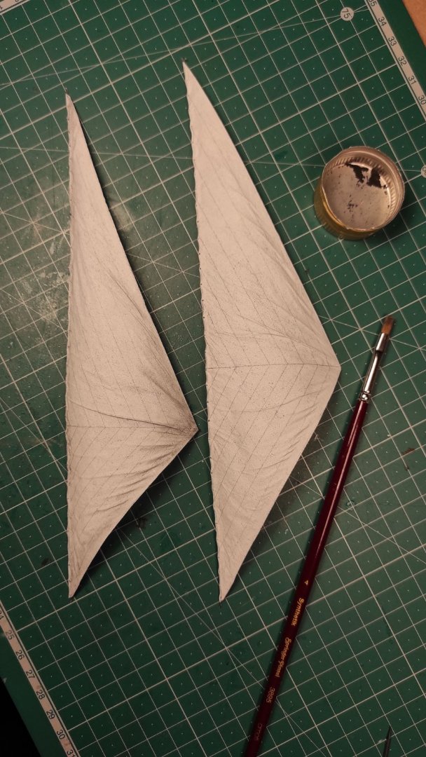
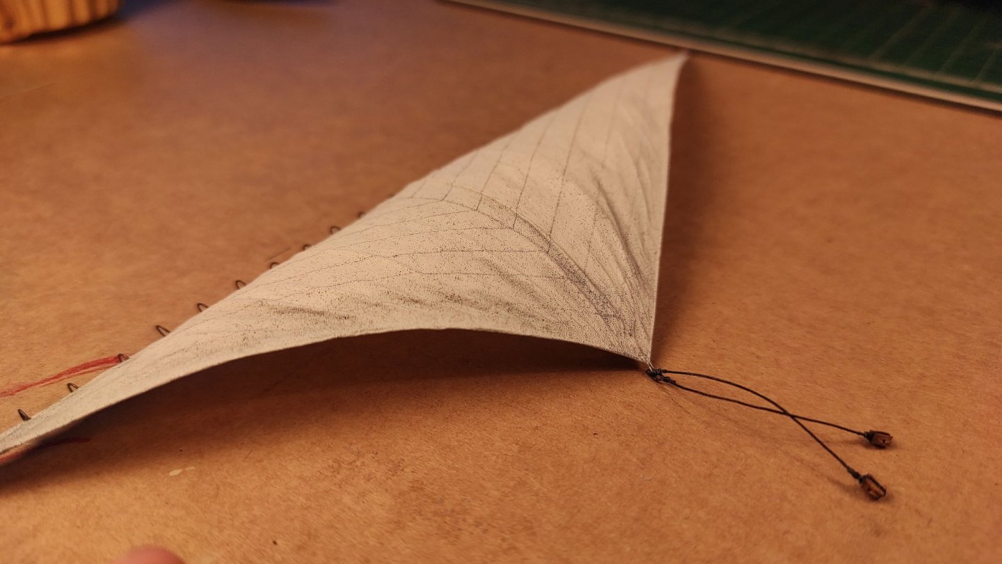
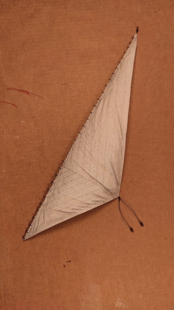
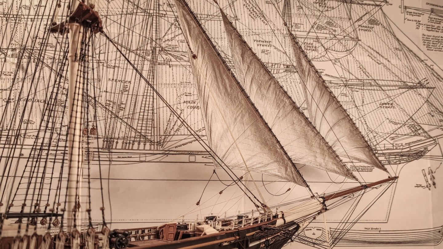
Thank you all for the likes and feedback, I really appreciate them. After spending so much time and effort it’s important to have unbiased opinions, and I’m happy to read that they are positive! And apologies for the delayed response. Busy days… As requested, I try to explain what I’ve done, but please bear in mind that this is my first sail model and those are my first sails ever, I am not, by any means, an expert… The raw material is modelspan. It comes in two different thicknesses, mine is the lighter one, the only one available for me at the time. I have no experience with the thicker one, but mine seems to be a bit too light. The modelspan’s color is pure white, and it is almost transparent. That’s why I have painted it with non diluted acrylic colors. I’ve used pure white mixed with ivory white and a dot of black. The paint has been applied on both sides with a flat brush. At the end of the process, the modelspan is flexible and wet, and I let it dry by hanging it on a horizontal pole. Meanwhile, I have created a paper model for each sail, using the Campbell’s sail plan scaled to match the size of the model. Using the paper model I was able to draw each sail on the painted modelspan. I have added a margin around each sail. It will be bent to simulate the outer frame. The seams line has been simulated with a sharp pencil. I have made some tests by gluing small strips of modelspan as the real sails, but this dramatically decreases the flexibility of the sail, so I opted for pencil lines. Once all was drawn, I cut the sail and this is the result: The edges of the sail are reinforced with 0.2 metal wire. It is important to straighten it as much as possible. After many tests I discovered (but surely many of you already know it) that twisting the wire makes it straight and robust. Since I work almost only late evening/night, I can’t use electrical tools… That’s why I’ve produced a wire twister with my trusted Lego Technic, here it is: The metal wire is then bent so that it can follow the profile of the sail, including the cringes, as you can see here: The edge of the sail is then bent over and glued with the wire inside using non diluted pva glue. Once dried, I opened the holes for the hank and I started to shape the creases on the luff side. I hope the image will clarify the process: Now I use a temporary holding pole to hold the luff side: With all in place, it’s time to shape the sail. I attach the pole to a chair and the clew to a mobile support, so that I can adjust the tension and the angle. A bag of flour is used to simulate the wind pressure. Flour is soft enough to take the right shape and, if all goes well, you can reuse it at the end of the process to prepare e pizza and celebrate the event with the family! With all in place, this is the setup: Sorry for the poor quality of the picture, but this was my first sail and I was a bit nervous. I then spray water on the bottom of the sail. The modelspan becomes soft and creases start to appear. Once satisfied I dried the sail with an air drier. The dried modelspan retains the shape of the small creases, while the metal wire helps to retain the overall shape of the sail. The temporary pole is then detached and the sail can be weathered. To do that I used graphite powder (obtained from a standard pencil) applied with a dry brush. Here you can see a clean sail on the right compared with a weathered one on the left. The hanks are made from a blackened wire twisted around a pole, and cut in small rings. The rings are then passed through the premade holes on the luff side, secured in place with a dot of CA gel glue and slightly opened. Sheets and relative blocks are also fitted. With the sail prepared, is now time to install them on the stays. The openings in the rings are needed in order to let the stay pass through each ring. I literally hang the sail on the stay. Now I can close each ring (using flat pliers) with the stay inside, securing the sail. Tacks, hallards and downhaul are then fitted, passing the lines through the metal cringes on the sail. The last ones are the sheets. I set the sail at the desired angle (a bit more than desired to counterbalance some relax effect) and keep it in place with the help of a helping third hand. I then pass the running rigging on both sides. Setting them loose on windward and tightening them on the leeward side. The tightened lines are then painted with CA glue, while the sail is kept in the desired position. Once dried the lines keep their shape and sustain the sail simulating the wind push. This last image is to answer rwiederrich’s question about translucency: This is how they look in backlight condition. I’m not too disappointed. That’s it… I hope it’s understandable even with my bad english. If you have any doubts, please write me and I’ll try to answer! Thank you all again for the feedback and support!


- 399 replies
-
- 21
-

-
-

-
- cutty sark
- revell
- (and 2 more)
-
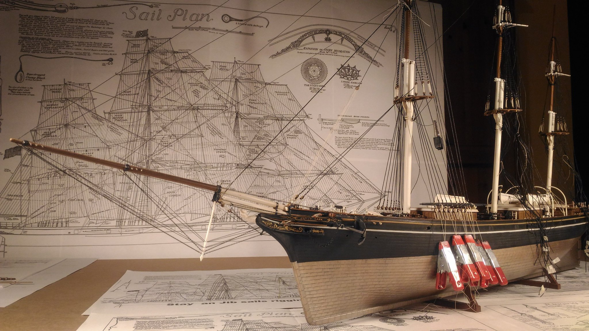
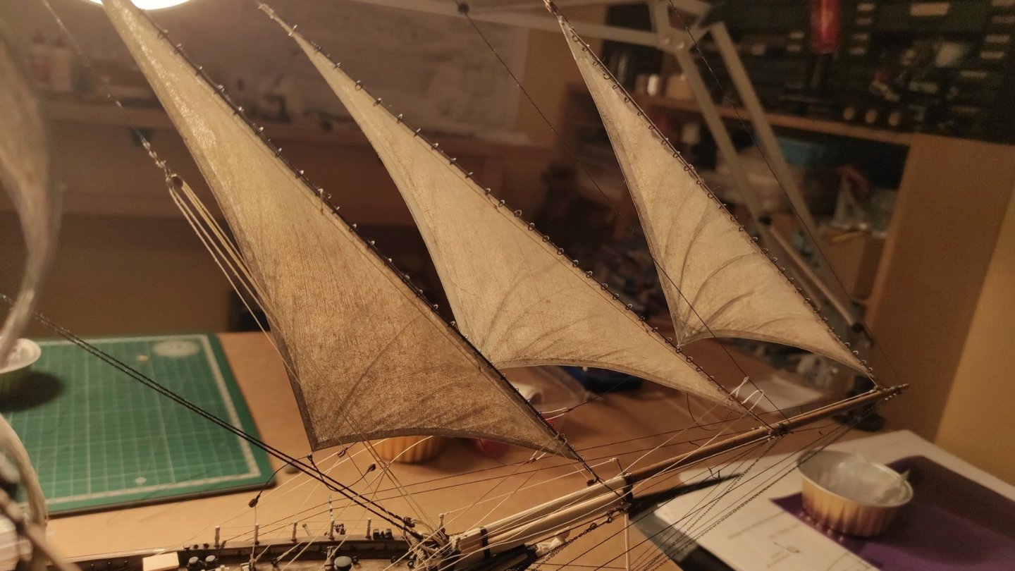
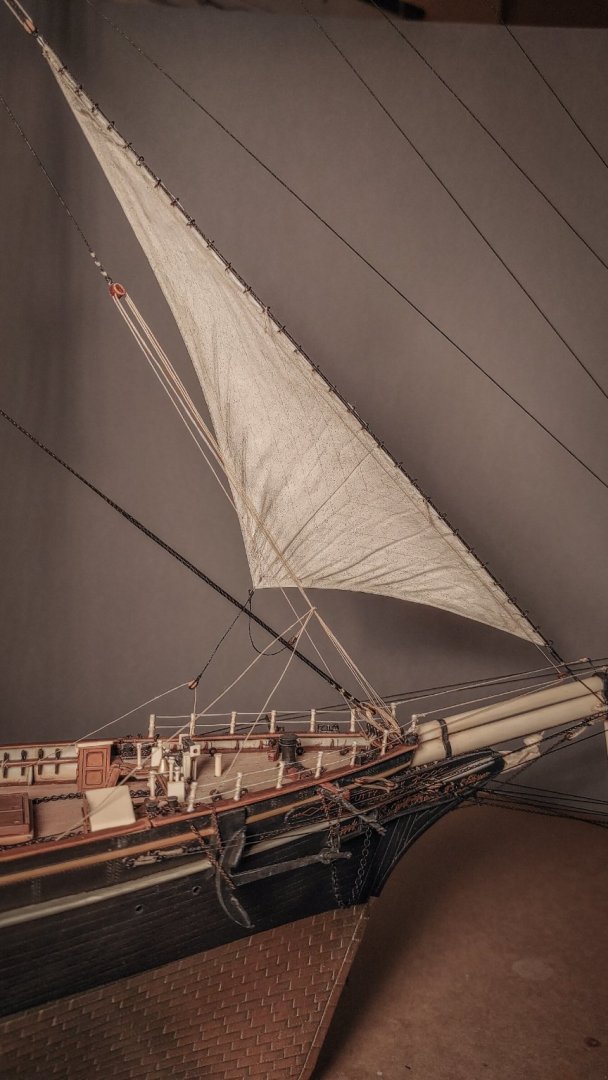
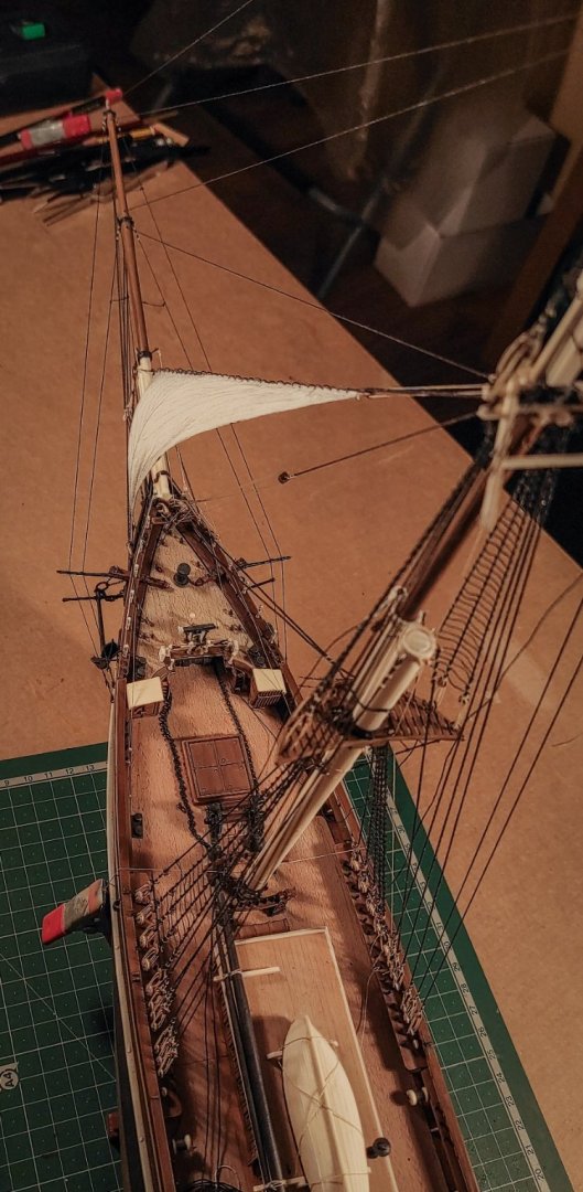
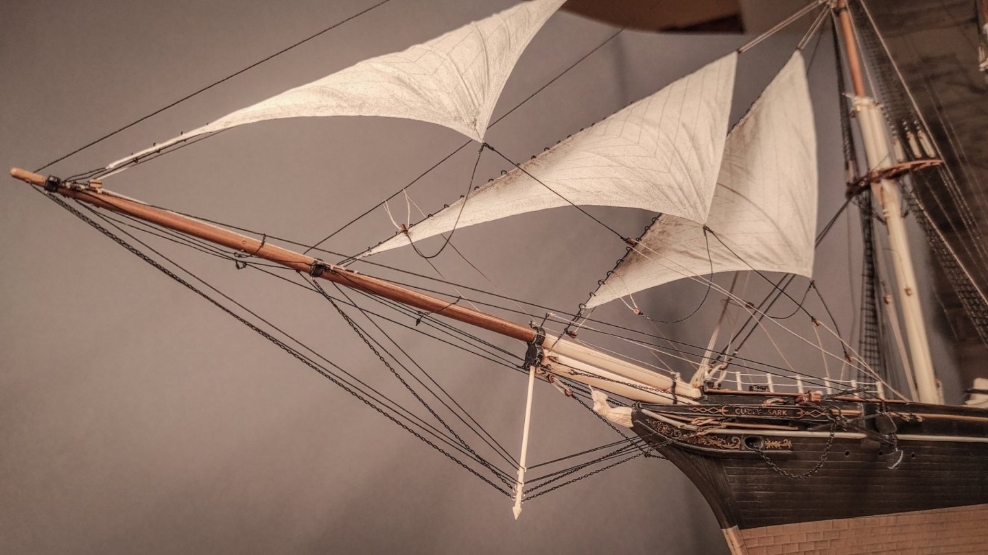
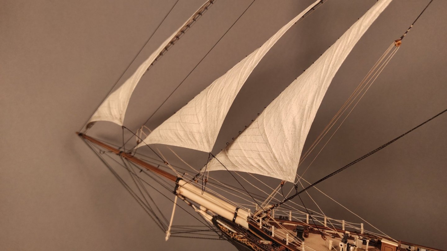
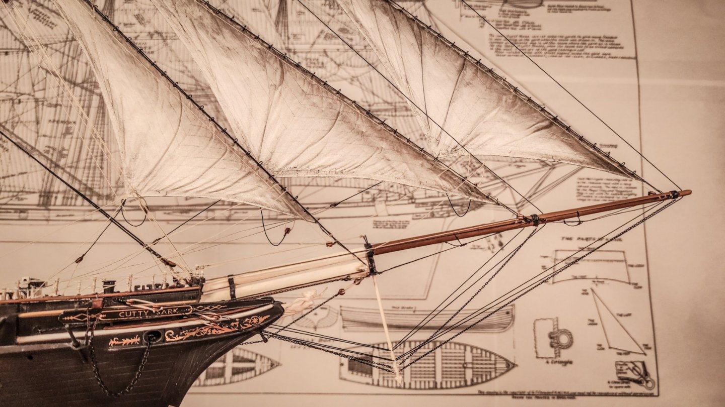
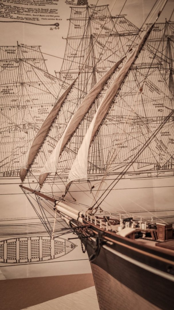
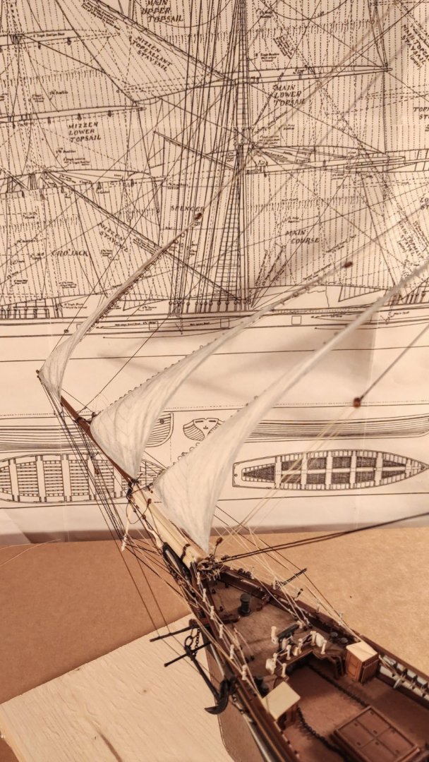
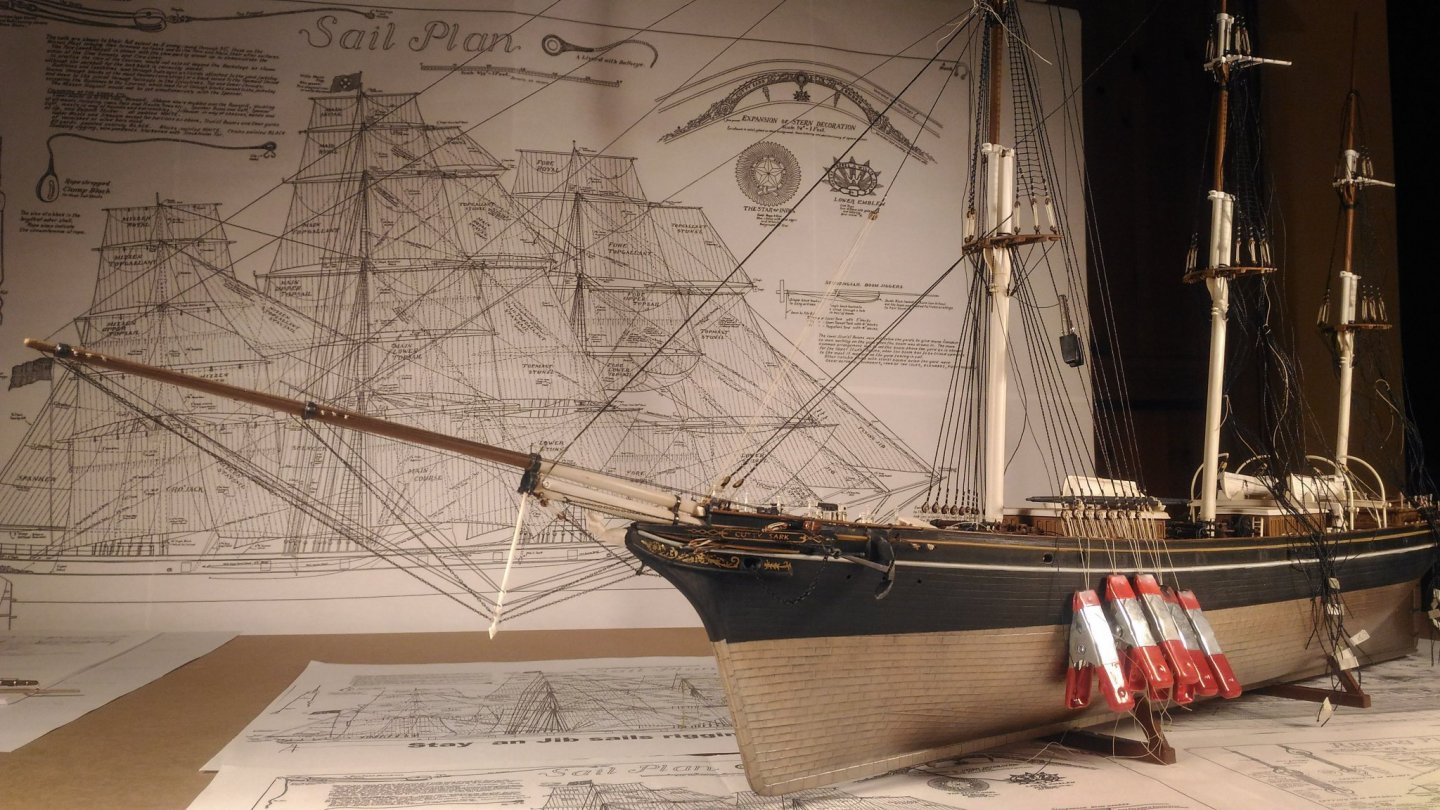
Sails! I have always had in mind to display my Cutty Sark under sails. A clipper with a full set of sails shaped by the wind is one of the most beautiful pictures I can think of. But when it comes to ship models, sails can easily ruin a fine job if not done properly. That’s why I set myself a number of targets when I started to make them. They should have been: - light and thin; - translucent; - with no visible canvas texture, too small to be seen in 1/96 scale; - shaped by the wind, not standing still and flat from yards and stays; - with visible creases near the clews and hanks; - strong enough to withstand all the standing and running rigging tension, since I want to display them with all the lines needed. After many tests with different materials and techniques, I opted for the modelspan. And this is the result on the fore topmast staysail: And here there are the jib and flying jib too: All the sails are rigged with halliards, downhalls and relative lizards, sheets on both sides, one under tension (on the lee side) and the opposite slaked, and tacks. The bowsprit rigging is also completed, with footropes, metal covers for the rollers for the fore topmast stay. There is surely room for improvements, but overall I’m not too disappointed, and I think I will keep on adding all the remaining 23 sails... I hope you like them!

- 399 replies
-
- 18
-
-
-
- cutty sark
- revell
- (and 2 more)
-
Great job on the hull! I really like it! You are adding a ton of nice details. I have some doubt about the tops and the crosstrees. They need to have openings near the mast's hole. In your model there is no space for the shrouds to go through the tops and crosstrees and this may cause you serious trouble for the standing rigging. To be clearer, you might have a look at my cutty sark: page 3, post # 71 My model is far from being a reference, but I hope the images can help you to better understand the issue.
- 207 replies
-
- 1
-
-
- billing boats
- cutty sark
- (and 1 more)
-
Yes, I stated my motivation in one of the above post, I copy and paste it here: They are overly simplified, so that it is almost impossible to fully rig them in the proper way. Moreover, they present features which are completely wrong, such as the sheave at the yard end, which are centered and not set aside and incredibly bulky. To make matters worse, the plastic is quite soft, and they are prone to bending when force is applied. So I decided to scratch build them. That being said, you can use the plastic ones, it all depends on what you want to achieve and how much time you want to dedicate. For me it has been a great satisfaction to build my own yards and I have learned a lot! Do you mean the ring band on the yards? If so, they are stripes of copper trimmed properly, bent and glued to the yard. The rings for the studding sail booms are also made in the same way, but I soldered them to the supports. If you need more, write me, and I'll try to answer! Thank you for your comment! Marco
- 399 replies
-
- 4
-
-
- cutty sark
- revell
- (and 2 more)
-
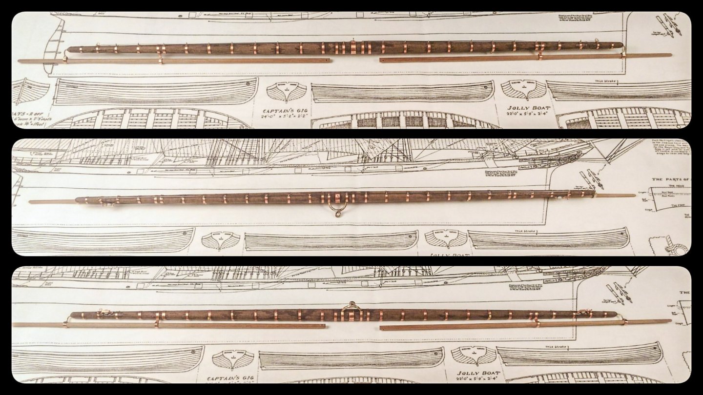
Hello Vladimir, thank you for your kind comment! I have almost no experience with enamel paint (I guess it was a typing error with "email paint", damn automatic corrector:) ). I prefer to use acrylic colors and spray them with the airbrush. I usually use the standard brush only to highlight details with dry brush or recesses with wash and filters. For that purpose I usually use oil paints. Anyway, the base coat of Munz metal on my Cutty has been done by brush, due to a temporary problem with my airbrush. And the color was not diluted. There are two coats of color and the result is a uniform copper-goldish tint. The non uniformity visible now is created by oil washes, mixing green and blue in different percentages to break the uniformity. Please bear in mind that the enamel thinner used for the oil wash will wash away the enamel color below! This is another good reason for having an acrylic base coat and not an enamel one. Please let me know if I can help you with further details! And, by the way, is there a build log of your plastic Cutty Sark? I'll be glad to follow you! Update time! Fore yards progress: Encouraged by the first test on the lower yard, I have adopted the same techniques for all the remaining fore yards. Here you can see the result: The lower yard is already painted and fitted with blocks. Still a lot of work needs to be done, but they are starting to take shape! Please note that there is an error on the upper topsail yard: the jackstay is too short. I already fix the issue, but it is still there in these pictures. Thank you all for the comments and likes!
- 399 replies
-
- 10
-
-
- cutty sark
- revell
- (and 2 more)
-
No, I'm sorry Cirdan, it's my fault. I mean an electrical drill handled by hands, not fixed to a vise such as a press drill. Life is hard enough! 🤪 Yes, that's why. Without clear evidences, I have chosen the one I like the most. I have never seen the drawing you have posted, may I ask you the source? It is not from Hunderhill, neither from Longridge... It's new to me. Thank you!
- 399 replies
-
- 1
-
-
- cutty sark
- revell
- (and 2 more)
-
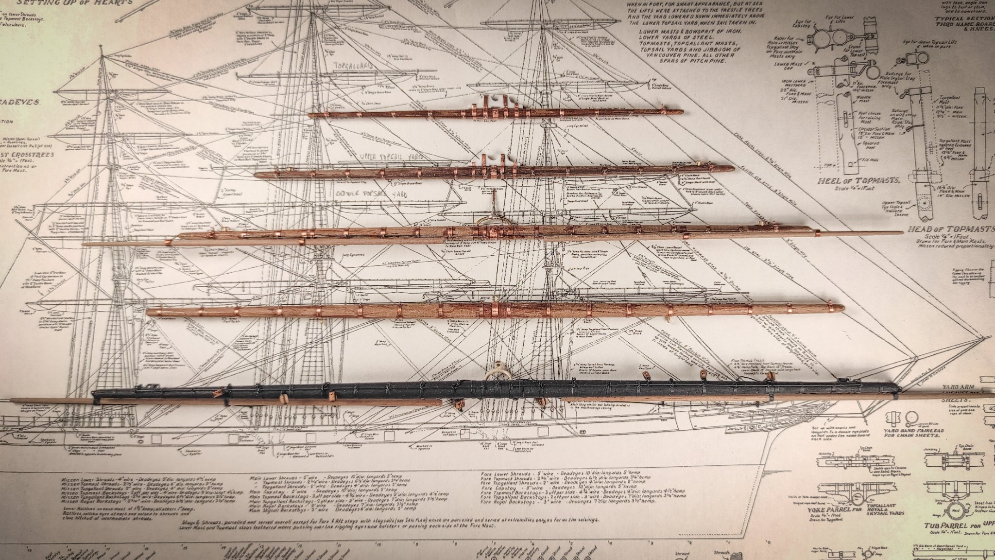
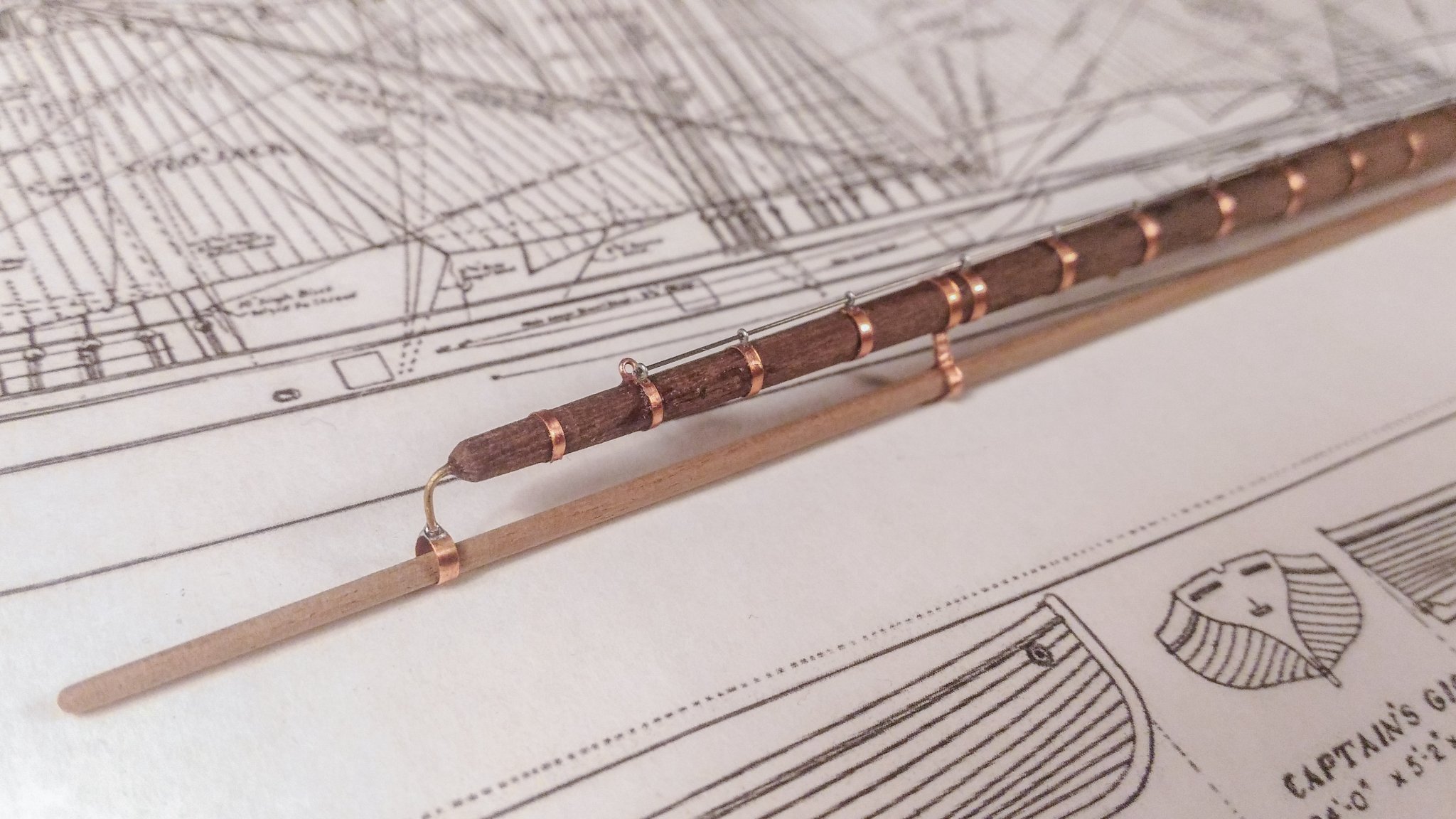
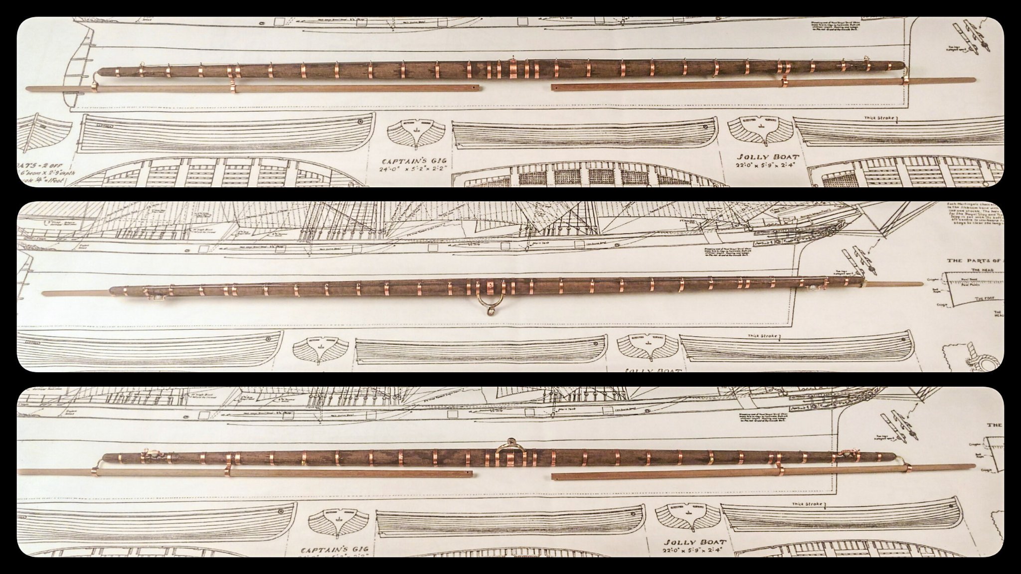
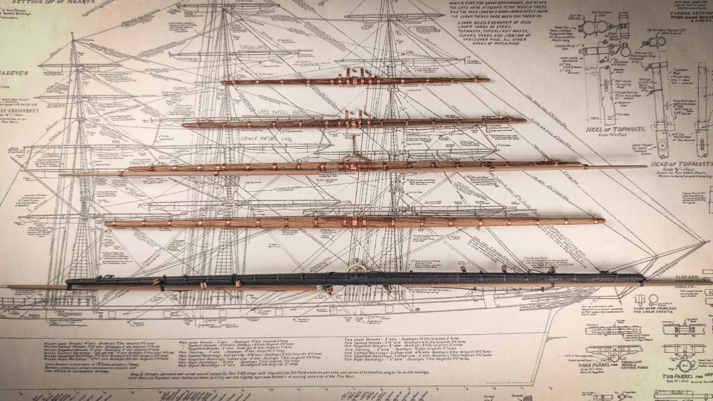
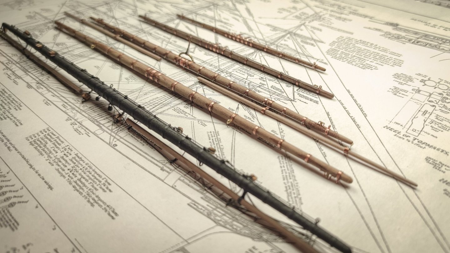
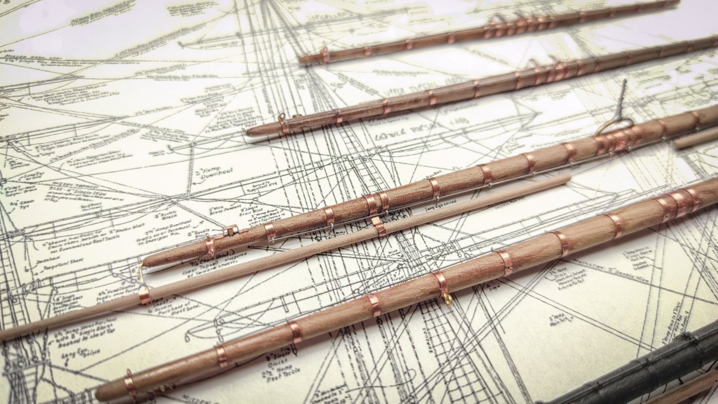
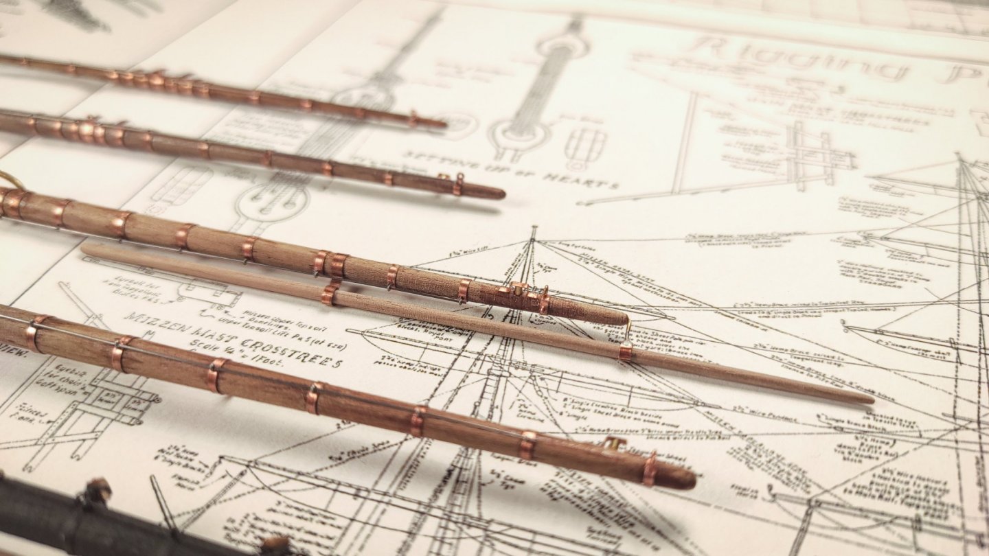
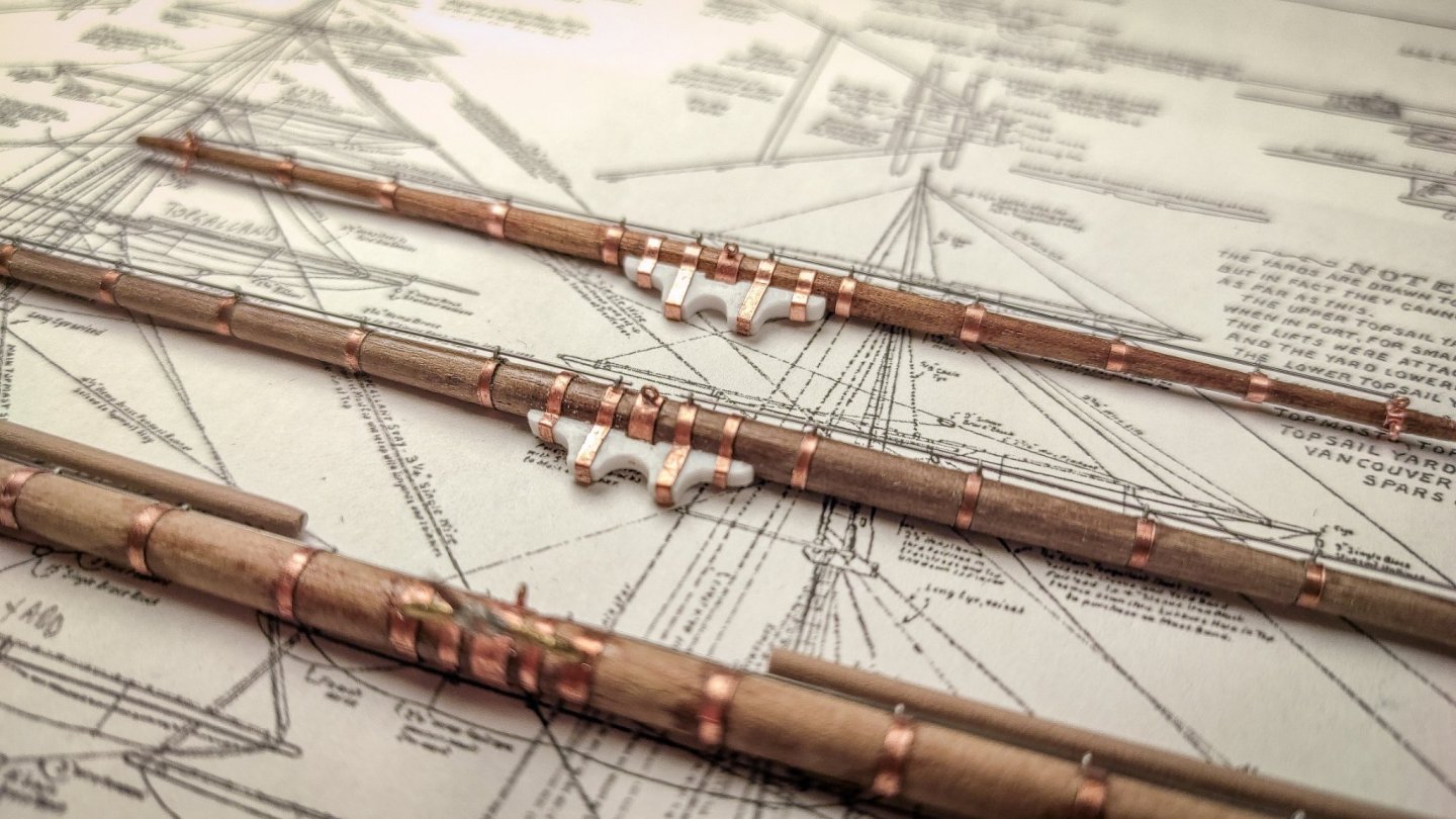
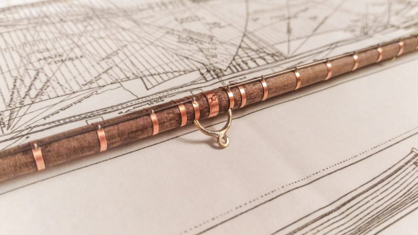
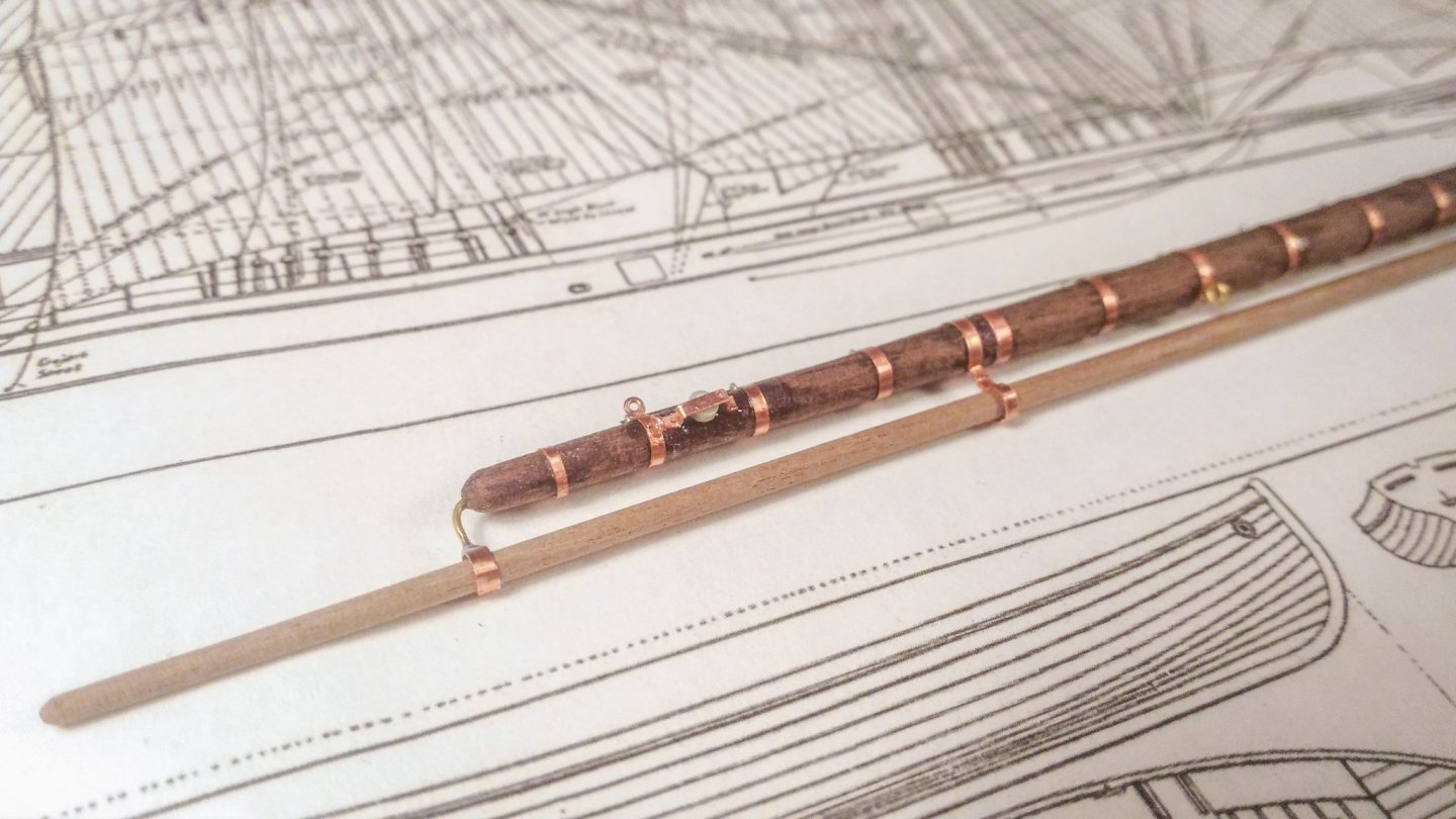
Hello everyone! I would like to share some more updates about my humble attempt. Fore yard. The yards proposed by Revell are one of the weakest points of the entire kit. They are overly simplified, so that it is almost impossible to fully rig them in the proper way. Moreover, they present features which are completely wrong, such as the sheave at the yard end, which are centered and not set aside and incredibly bulky. To make matters worse, the plastic is quite soft, and they are prone to bending when force is applied. So I decided to scratch build them. This is an entirely new field for me, I have never worked with wood and metal in model making. The first big issue is to find a reliable source. Again, Campbell and Longridge show slightly different solutions. I ended up making my own decision based also on my personal taste. For instance, Longridge presents metal bandages on the entire length, which seem to be absent in Campbell’s plans. I like them and I have modelled them (dumb choice: it takes hours to made them…). Other features, such as the upper topsail sheets, are not present in the Longridge version but clearly visible in Campbell’s plans (and described by Underhill) and I decided to include them. After a long study session, I started to model the fore lower yard. The starting point is a cylindrical wooden bar, tapered at each end using sandpaper and a hand drill. At the end of the process the shape was quite right and, more important, I still have all my fingers in place. Dimensions are taken from the scaled Campbell’s plans. Then I started the metal work. The first feature was the cantilever mechanism at the yard’s center. Here I made some compromise in order to have a stronger joint between the mast and the yard. Still I tried to get the overall shape right. This is the result: With the first milestone achieved, I have started to reproduce the metal bandages. Numbers, positions and thicknesses are taken by Longridge plans. Next comes the jackstay. I drilled small holes on each band and fitted them with a hand made small eyebolt, the smallest of the entire build. Then, the jackstay bar is passed through them. They are made out of spring steel, 0.4 millimeters in diameter. Then, it’s time for the sheaves of the chain sheets. The rollers are made of plastic, while the central bar and the external cage are in metal. The central bar is glued in place inside a predrilled hole in the spar in order to make it stronger. The lower yard is also fitted with studding sails boom and relatives supports. They are made of brass wire and small copper bands The last features are the eyebolts for lifts, braces and blocks. Last but not least, the metal fairleads for the chain sheets. Here you can see details and a global view of the yard before the painting job. The entire process takes a lot of time, and here we are just half way: still need to paint and weather it, and fit all the blocks (wooden and metal ones). I hope you like it!

- 399 replies
-
- 11
-
-
- cutty sark
- revell
- (and 2 more)
-
I'm sure I know the reason: they were completely useless for the real ship, but they have installed that poles just to drive me crazy while trying to rig the bowsprit! I spent countless hours in that area... Ok, now that I know he was working at almost the same scale I'm working, I'm officially sad. There was a time when I was almost proud of my Cutty Sark, a time which is now gone! Joking aside, it is a really nice model, thank you for sharing!
- 399 replies
-
- 2
-
-
- cutty sark
- revell
- (and 2 more)
-
What a great find Cirdan and Kirill! I was aware only on the volume 4, by far the less interesting of them all. Thank you!
- 399 replies
-
- 1
-
-
- cutty sark
- revell
- (and 2 more)
-
Fore course clewline belaying pin on Cutty Sark
Bruma replied to Bruma's topic in Masting, rigging and sails
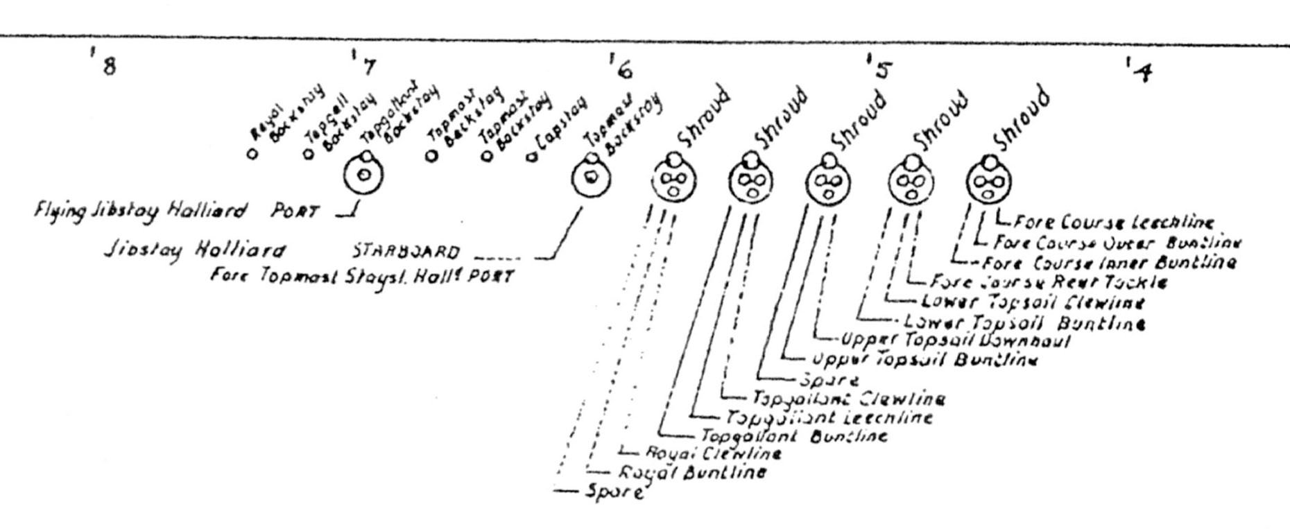
Thank you, John! You are right, the fairlead is not mentioned by Hunderhill for the clew garnet, it might be a good clue for your interpretation. It sounds weird to me, I always look at the rigging as a smart, perfect and elegant mechanism and having a single line without fairlead while all the others have one, seemed strange to me. Thank you again! -
Hello everyone. I'm studying the running rigging of the Cutty Sark and I have a question: in Campbell's plans there is a clear indication of each line going through the respective fairleads. They are all present, except for the course clewline (while the lower topsail clewline are indicated, for instance) Different authors have different opinion about the subject: Underhill suggests that the clewline should be belayed to the main rail (if so the relative fairlead is missing in the Campbell's plan), while Longridge suggest belaying the clewline on the fife rail, without specifying the pin (but this version would explain why the fairlead is missing in Campbell's plans). Do you have any ideas? What should I do? Thank you in advance!

-
Ok, I'll put away the wirecutter! 😉 Talking about railings, I still have to add the rounded section at each end. It will be pretty fragile, and I'll wait a bit further to install them. By the way: I have a question about fore course clewlines balying pin, you can follow the relative thread here if you have any hints:
- 399 replies
-
- 2
-
-
- cutty sark
- revell
- (and 2 more)
-
Can you please elaborate a little more? What do you mean for "prominent side rail"? Images are welcome! 🙂
- 399 replies
-
- 1
-
-
- cutty sark
- revell
- (and 2 more)
-
Thank you Vladimir, you should really start to build your kit, rigging the Cutty Sark is a lot of fun! And thank you all for the likes!
- 399 replies
-
- 2
-
-
- cutty sark
- revell
- (and 2 more)
-
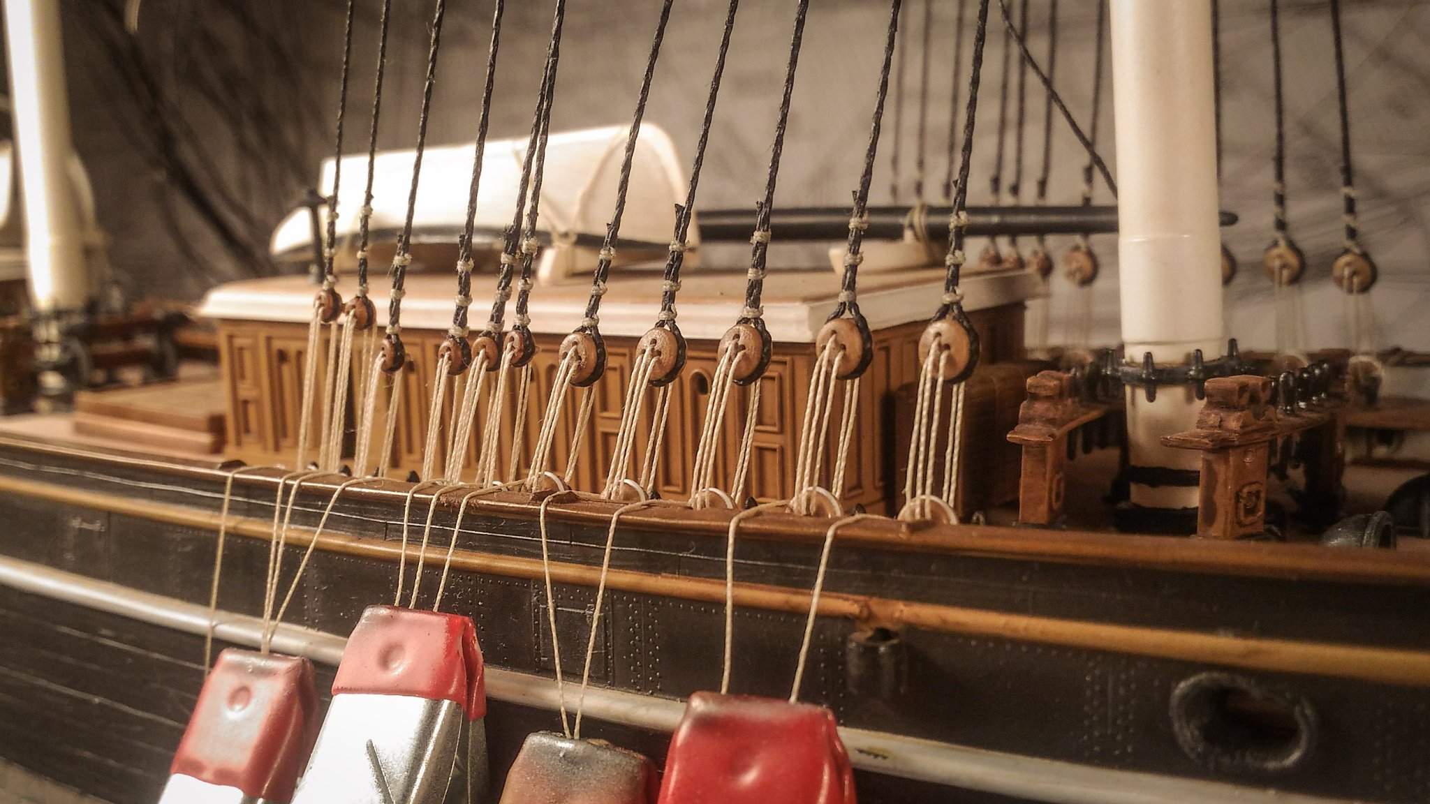
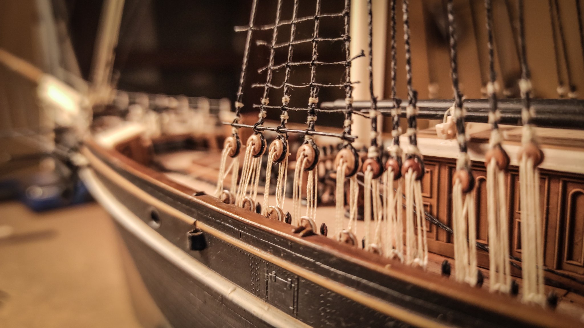
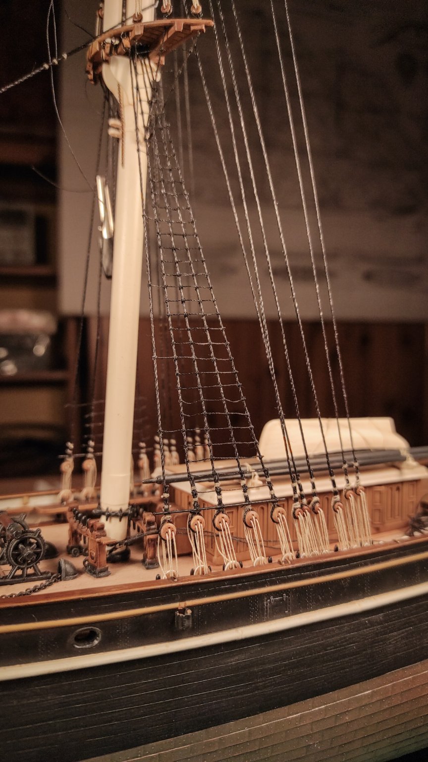
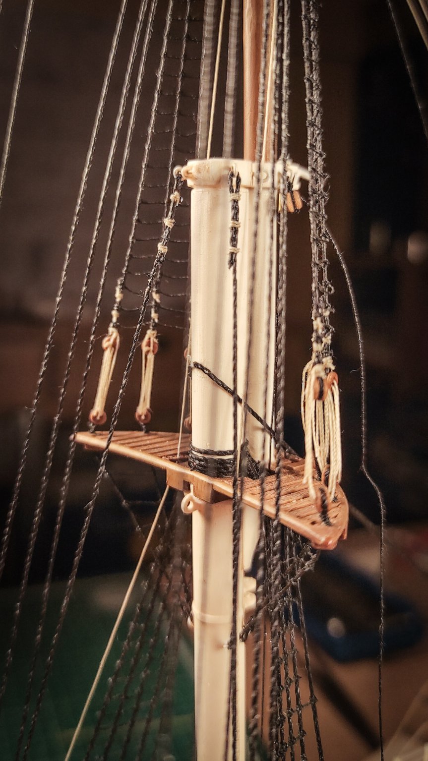
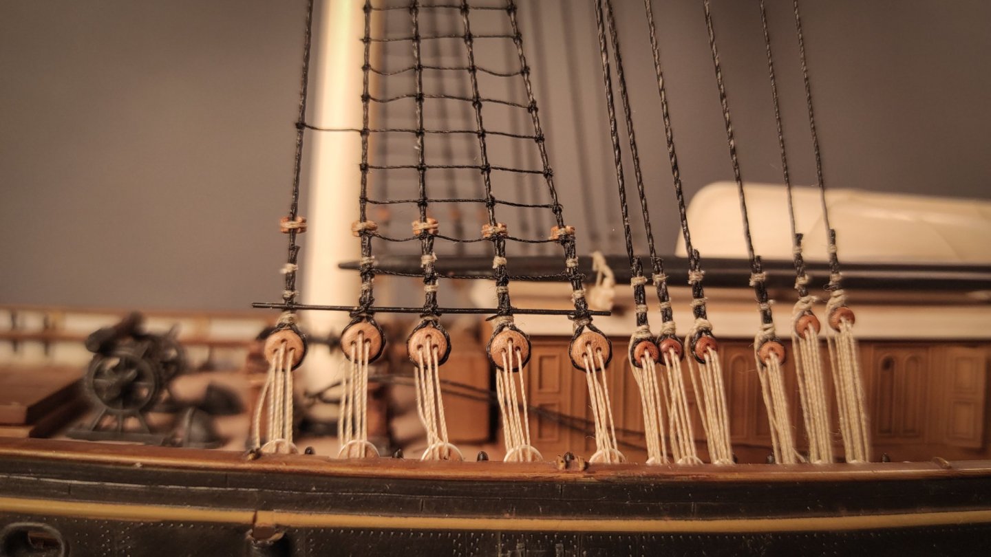
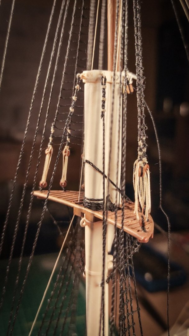
I completely second that! All we surely know is that we don’t know enough. That’s why, without sure information, I've never ventured in major transformation of the kit. Looking for new evidence and getting to know the history of the ship is a wonderful adventure, investing countless hours to modify a shape that might turn out to be wrong, is just looking for mental diseases 😅 Updates time! Stepping the fore mast: shrouds, ratlines, fairleads, fore stay and fish tackle. As mentioned in the previous post, in order to complete the bowsprit rigging it’s necessary to fit the fore mast. After many dry fit tests, I decided to move on (not without a lot of apprehension), and to glue the fore mast in place. I decided to use the CA gel glue, it dries slowly, it’s quite thick, and it creates a strong bond when dried. Particular care was dedicated to have the right longitudinal slope of the mast itself. The angle should be (according to Longridge) 86 degrees. (85 and 84 for the main and mizzen respectively). Once the glue has dried, I have started to tie the shrouds. The distance between deadeyes has been eyeballed, without using dedicated tools. In order to balance the stress on the mast I have started from the fore shrouds, always going on pair, port and starboard. The lanyards have not been tied until all the shrouds were secured in place. In order to keep an even tension in all the lanyards, I have used hanging clamps, visible here: And here a close up view: The fore royal backstays are still missing. There are differences on the mast length between the kit and the Campbell’s plans (which are shorter). I still have to figure out how to deal with it and I think I will come back to this once the royal yard and relative sail will be ready to set in place. After some days, once I was sure that the tension was even, I started to tie all the lanyards permanently. My first idea was to tie the ratlines only after all the sail has been placed. But I changed my mind. In fact, I would like to represent my Cutty Sark with full sails (except for stunstayls), with the yards braced on a beam reach. In this configuration the leeward shrouds are almost inaccessible. So I have started to tie the ratlines, here is a work in progress: In the above picture the sheer pole is also visible. It has been glued first (again with gel CA) and then tied up. After hundreds of clove hitches, the ratlines were completed: At this point, another detail needs to be added: the fairleads. They are made out of small deadyes (2 mm). I grooved the channel for the shrouds, glued the deadeyes to the shrouds and then tied them with small threads. This is the result: These one are only the main fairleads, topmast and topgallant backstays fairleads will come shortly after. Another view of the deadeyes and the fairleads: With the shrouds in place, I turned my attention to the forestay and to the fish tackle, both of them are visible here, in this horrible picture, sorry about that: The hearts of the forestay and the triple top block of the fish tackle are both scratch built out of plastic. I wasn't able to find a small enough in commerce and since they are pretty visible I decided to build my own. The hearts are also visible in a picture in the previous post, just in case someone wants to see them better. The last detail is the cleat for the forestay. It is also scratch built, and it is a copper wire flattened at one end. Enough for today, as usual thanks for following along and I hope you like it!


- 399 replies
-
- 11
-
-
- cutty sark
- revell
- (and 2 more)
-
Well, with all the due respect both for the modeler and the model, there are some elements not so accurate, at least in comparison to how the Cutty Sark is now and how it is depicted by Campbell. The bow and the figurehead location are the most visibile ones.
- 399 replies
-
- 2
-
-
- cutty sark
- revell
- (and 2 more)
-
Thank you shipman, They seem to be really nice. And the chain looks food too! I really hope so, even if I must admit I was not aware that the white sheer line has been introduced only during the Woodget's period.
- 399 replies
-
- 1
-
-
- cutty sark
- revell
- (and 2 more)
-
Thank you all for comments and likes! I really appreciate your participation to the build, regarding both the model and the history of the ship! You are right… I’m not satisfied with them too, but installing the new ones now is, sadly, almost impossible. Do you have the brass ones? Looking at the diagram provided by HisModels, it seems to me that the inner diameter for the railing is 1 mm, is it correct? If so, it might be still too big for my taste to justify the effort. It would be nice to see them side by side with the plastic ones. This is definitely one of the many problems of my model. Still, looking at the whole picture, I like the sense of lightness of the railing provided by the thin wire. I do the same with pictures from other modellers! I like this kind of therapy, as someone else mentioned! You will surely do better! Thank you, Dave and welcome aboard! I’m surely going to follow your build! Regarding the yards color… Well, I hope you are wrong Cirdan! I already paint mine in black! 😅 If more solid evidences of the “white version” should arrive, I’m going to act like a 96 times smaller Woodget, imposing my will and painting them in black just to satisfy my taste! 🤣 Aside from the jokes, this is a very interesting discussion, even if I personally think that colors and small fittings were constantly changed during the ship’s life, according to what was cheaper/more available.
- 399 replies
-
- 1
-
-
- cutty sark
- revell
- (and 2 more)
-
Ops, we were posting almost together, and I miss your question. Are you referring to the last chain I mentioned? If so, I hope I have answered your question at post #74. If not, let me know! Marco
- 399 replies
-
- 2
-
-
- cutty sark
- revell
- (and 2 more)
-
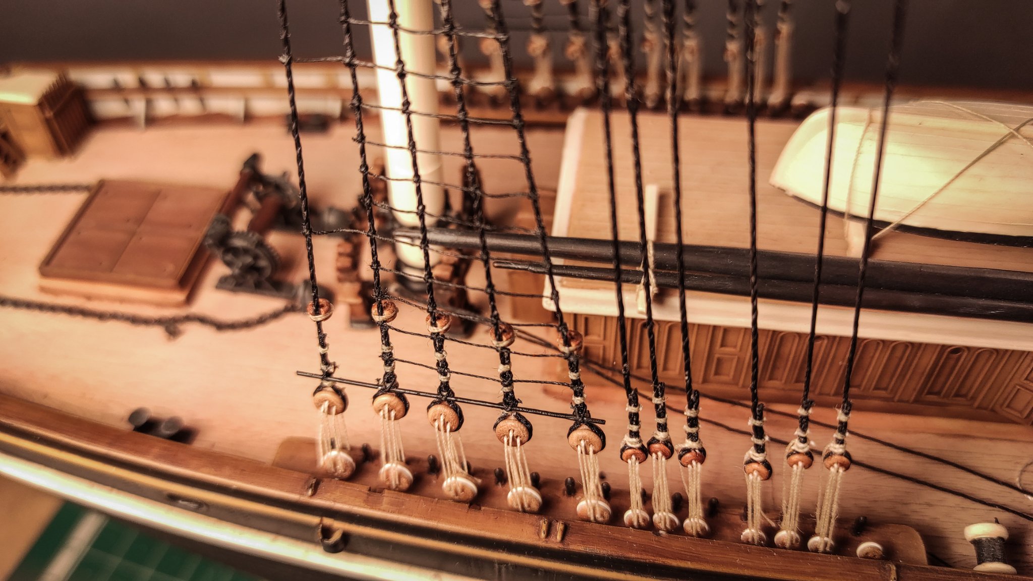
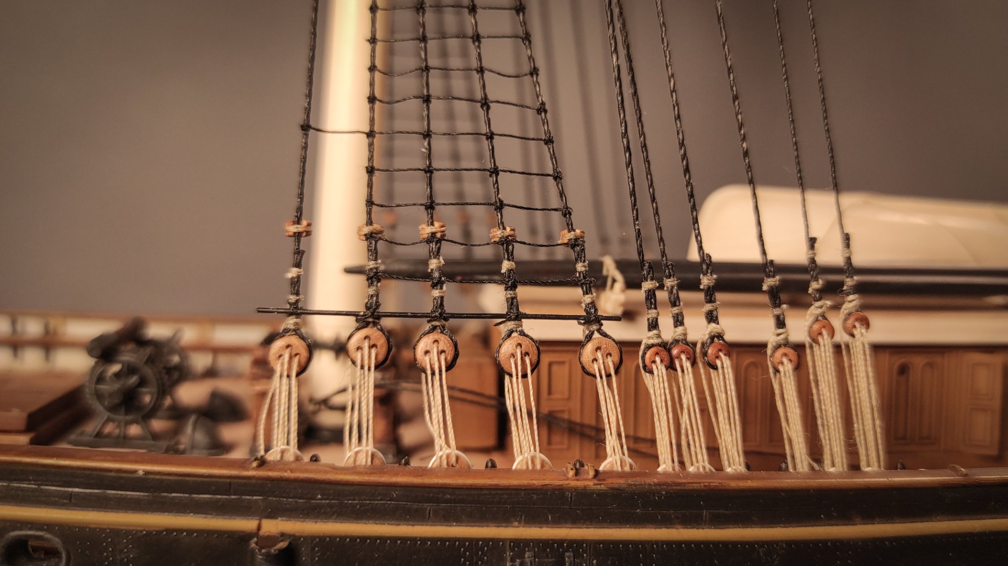
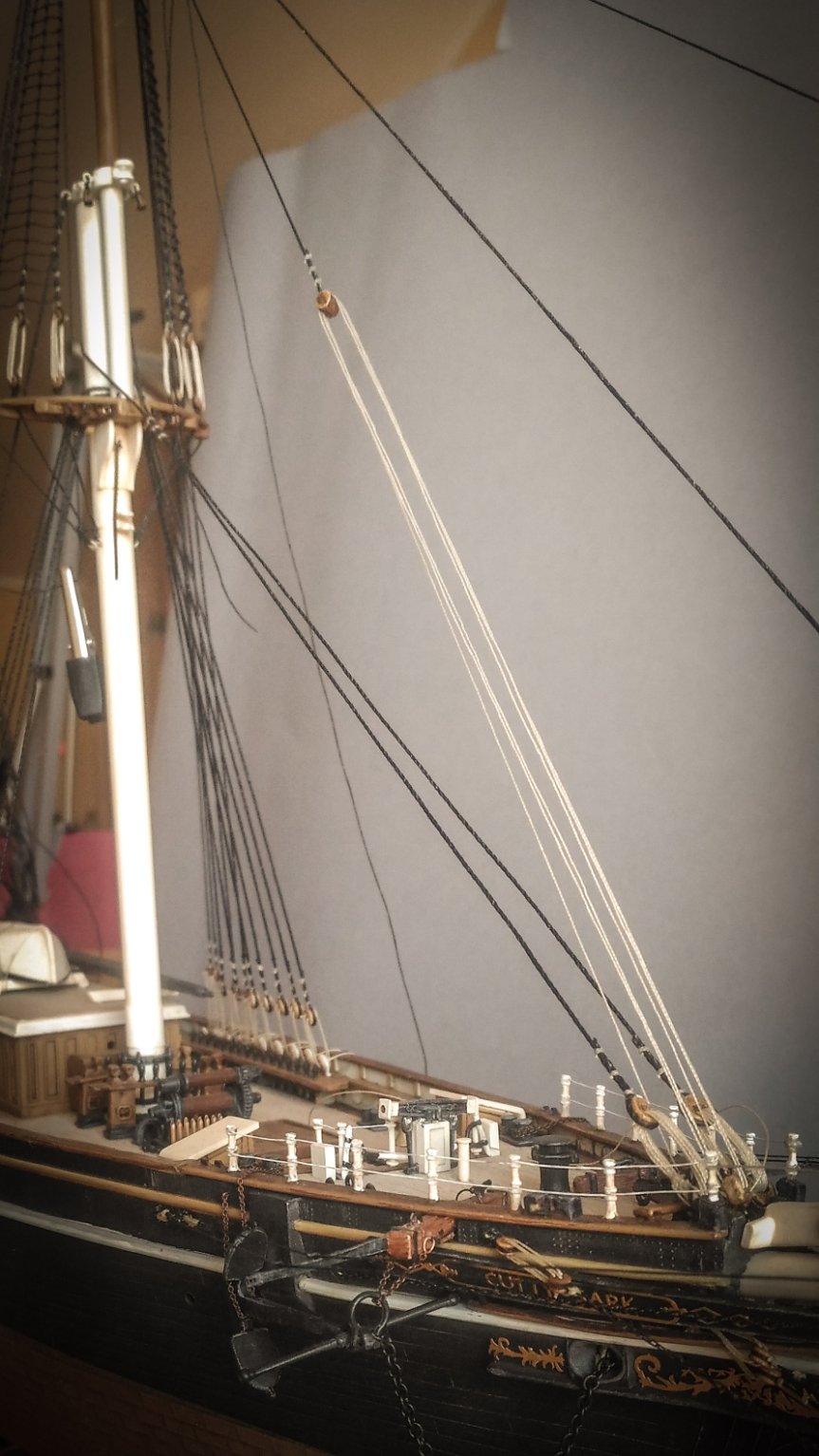
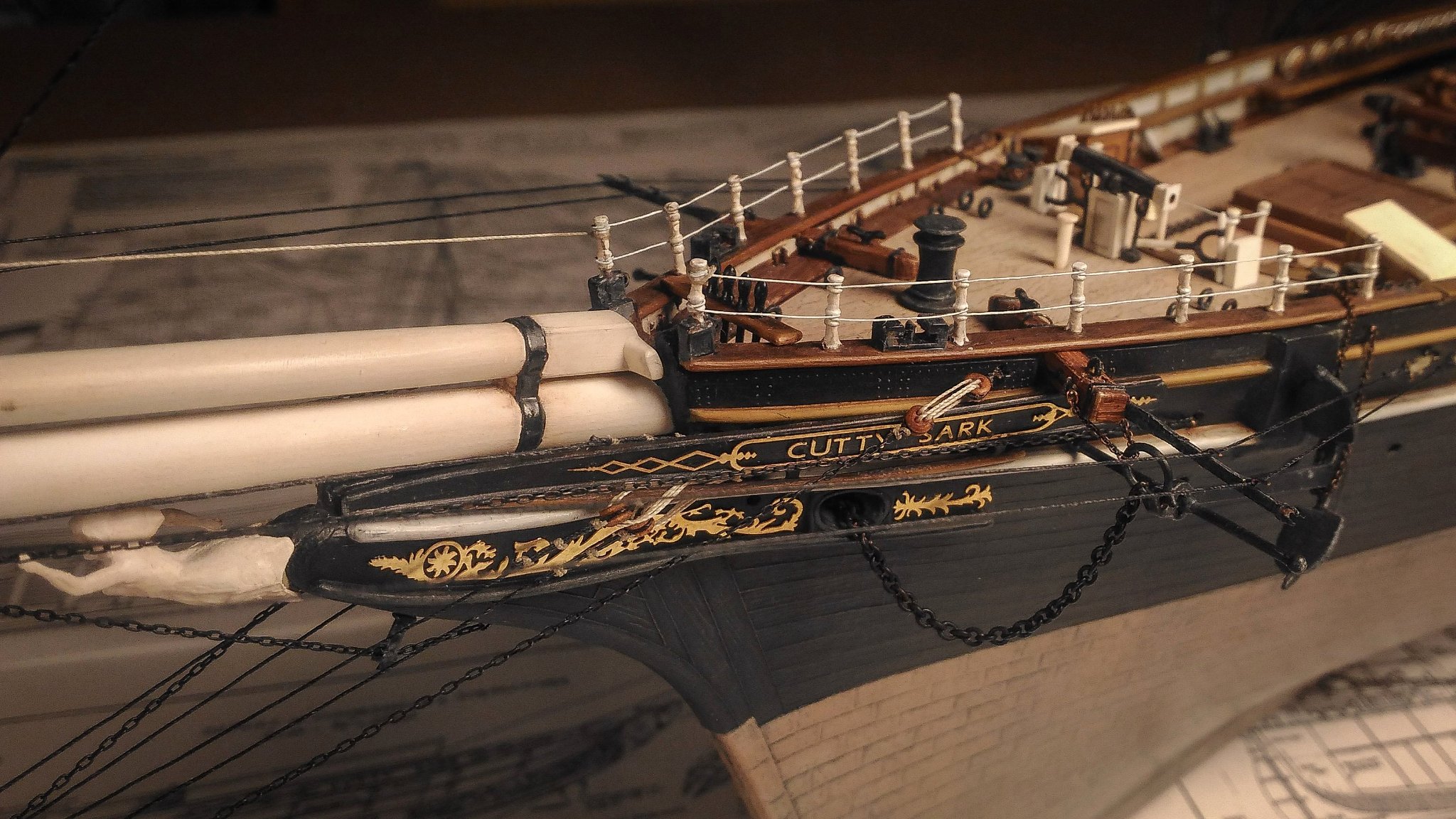
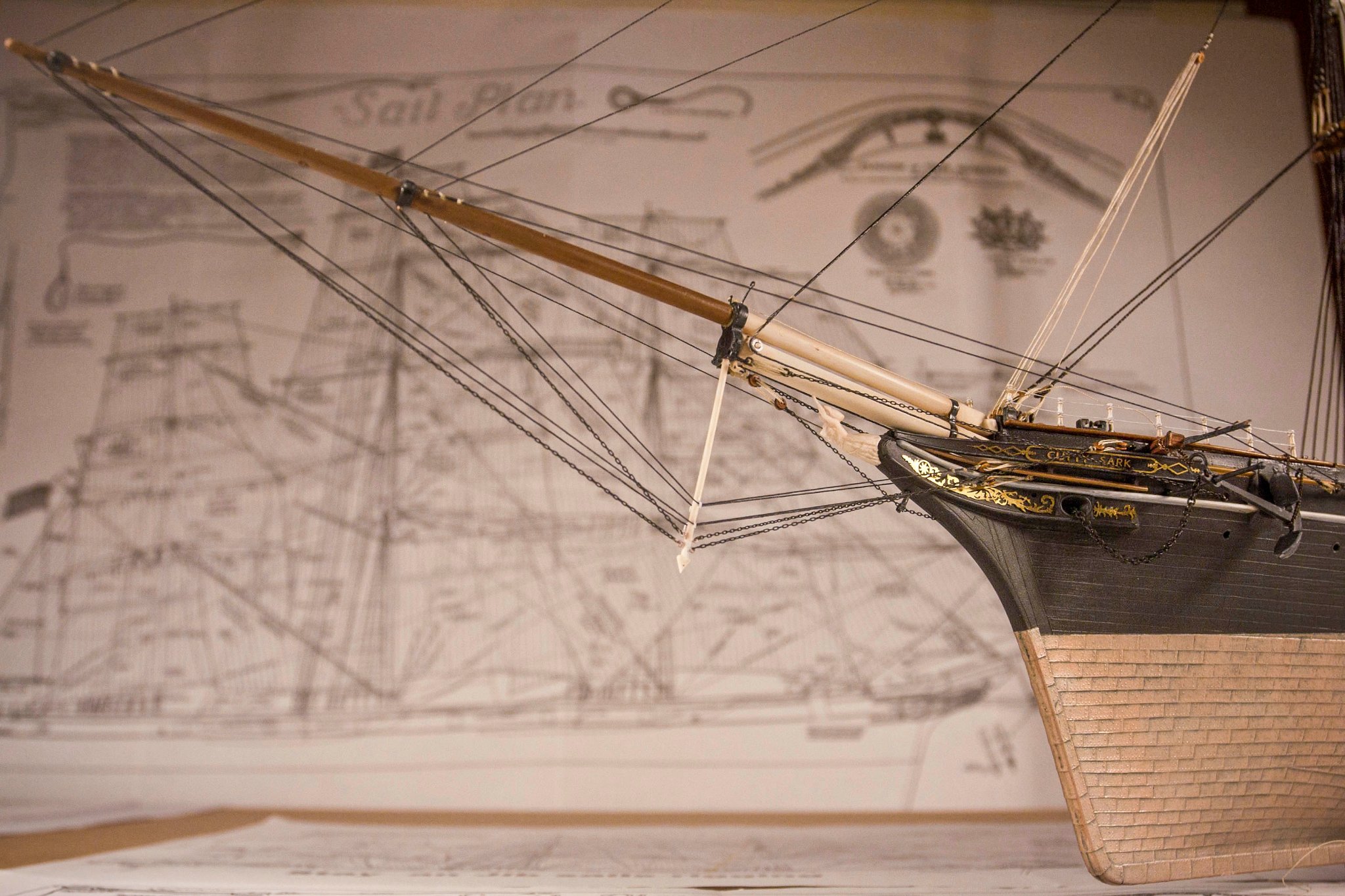
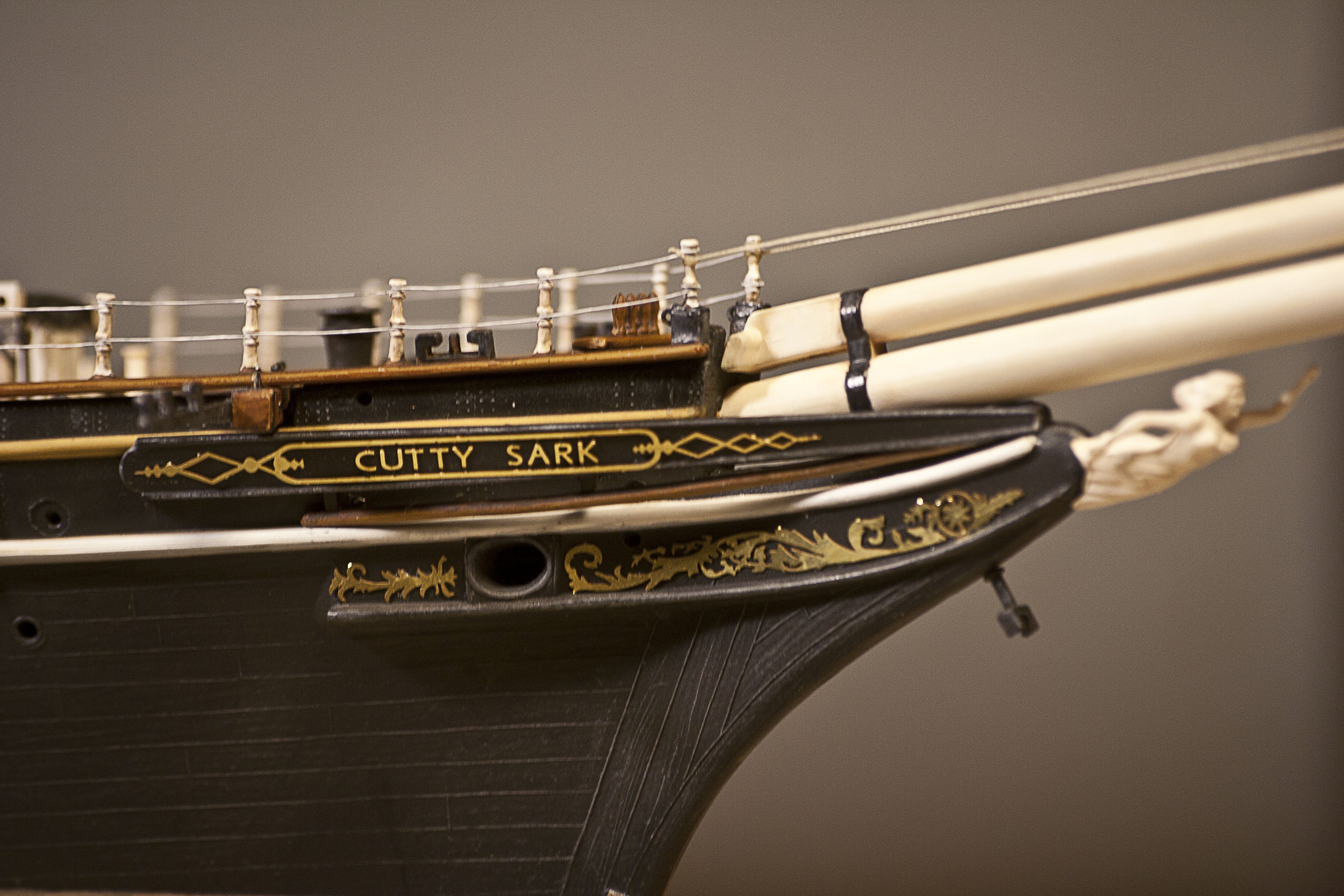
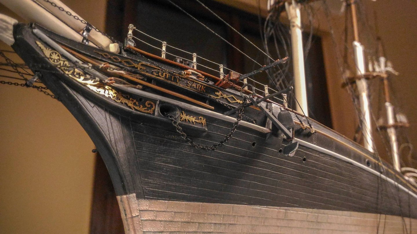
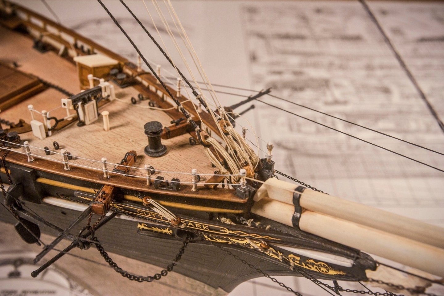
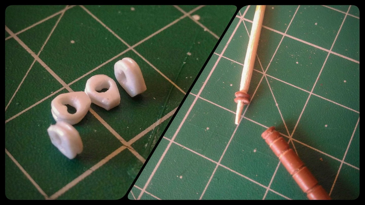
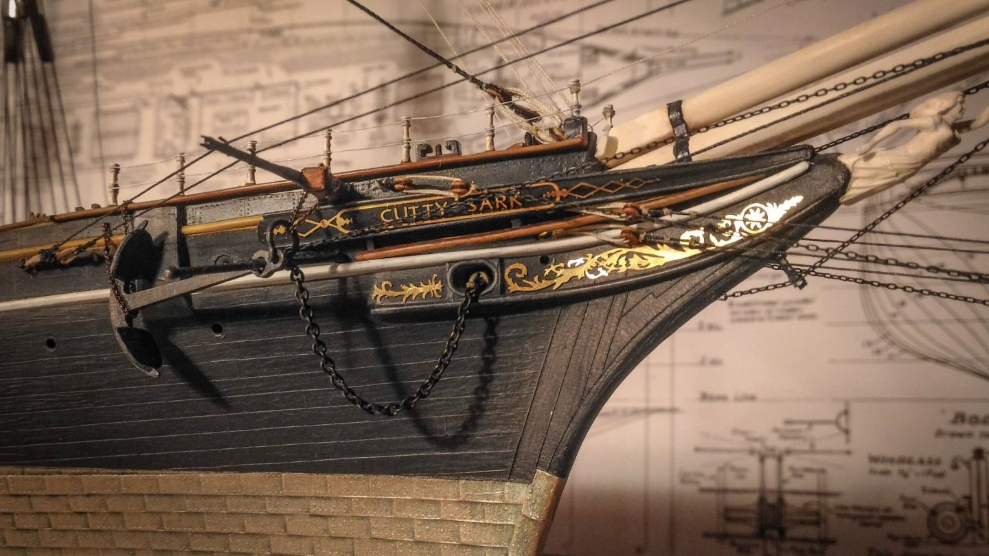
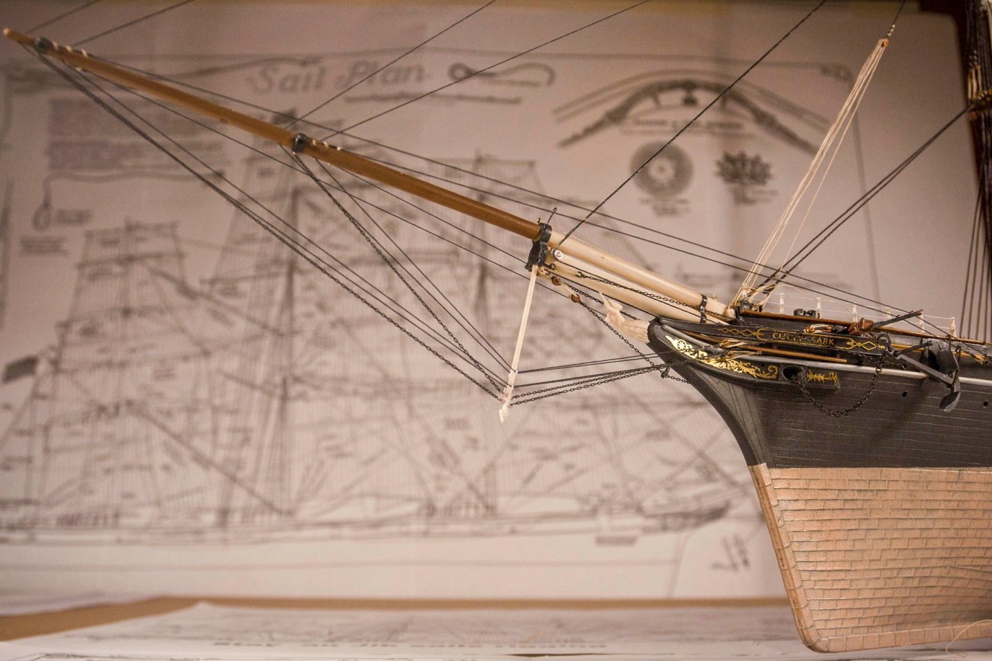
Thank you both for the information provided! Aside from the single page posted by Shipman, the entire site is worth a reading, here you have the direct link to the main page: https://www.johnsankey.ca/cuttysark.html There are many links along the reading, all of them are really interesting! One of them in particular catched my attention. It is about the painting as proper evidence. Here it is: https://www.johnsankey.ca/cuttysarkpaint.html It states that, contrary to what is shown in many paintings, the Cutty Sark has always had only three foresails. This was one of my many doubts, since many models and paintings showed four of them. Now I’m a bit more confident in my choices. Now, some updates: Anchors stowing and bowsprit rigging I decided to stow the anchors on the side of the hull. The anchor release mechanism is completely scratch built using copper and steel wires. Here you can see the anchors in their final position: The release bar goes through the side of the hull, alongside the cathead, and it ends with a curved handle wrapped around the cathead. More details are also visible here: The images also show details not present in the previous updates: the standing rigging of the bowsprit in a more advanced state. Martingale backstays, bowsprit guys, inner and outer jibbom guys are now fitted. I have tried to rig them at my best, again, in some places, small deadeyes were used instead of heart in some places. Somewhere else I used small iron rings, similar to the one now used on the real ship. Talking about hearts I was able to create my own hearts for the forestay. They are bigger and so easier to build compared to the one needed for the bowsprit. They are made out of plastic, carved, and painted with acrylics and oil. Here they are along the process, nearby the rollers for the fore topmast stay. And here they are in their final position: Unfortunately the sheaves on the cathead are not well represented. They are not present in the kit and I stupidly decided to add them once the catheads were already mounted and it was not that easy... This is just another chapter on the endless story about how many details add to the kit. The initial idea was to build it almost out of the box but “appetite comes with eating”... Aside from that, I’m quite happy with the result. In order to fit the forestay and the topmast stay, the mast needs to be secured in place. I will talk about it in the next update. One of the hardest things was to secure the topmast stay. They are a single line, which starts from the forecastle, goes through the post shave, runs up to the foretop, goes back to the starboard shave and down to the forecastle again. Balancing tension, holding all in place was a hard time.... Generally speaking, all this area was quite tricky, but also greatly rewarding! Finally, an image of the bowsprit almost completed with the standing rigging: Foot ropes are still missing and the rollers for the fore topmast stay are not completed. The outer chassis is missing, but it will arrive soon… I hope you like it, and I’ll see you next update!

- 399 replies
-
- 10
-
-
- cutty sark
- revell
- (and 2 more)
-
Ok Kirill, now I understand, thank you! And again, you are right, they are a bit too forward. This was the best compromise I was able to get with several constraints: deadeyes should have been smaller (1 millimeter) and this lead to have longer lanyards to keep proportions, and the bow railing is too narrow. Moving them a bit forward allows to have a straight line from the anchor point. This is definitely a tricky area... Thank you!
- 399 replies
-
- 2
-
-
- cutty sark
- revell
- (and 2 more)