DanielD
-
Posts
543 -
Joined
-
Last visited
Content Type
Profiles
Forums
Gallery
Events
Everything posted by DanielD
-
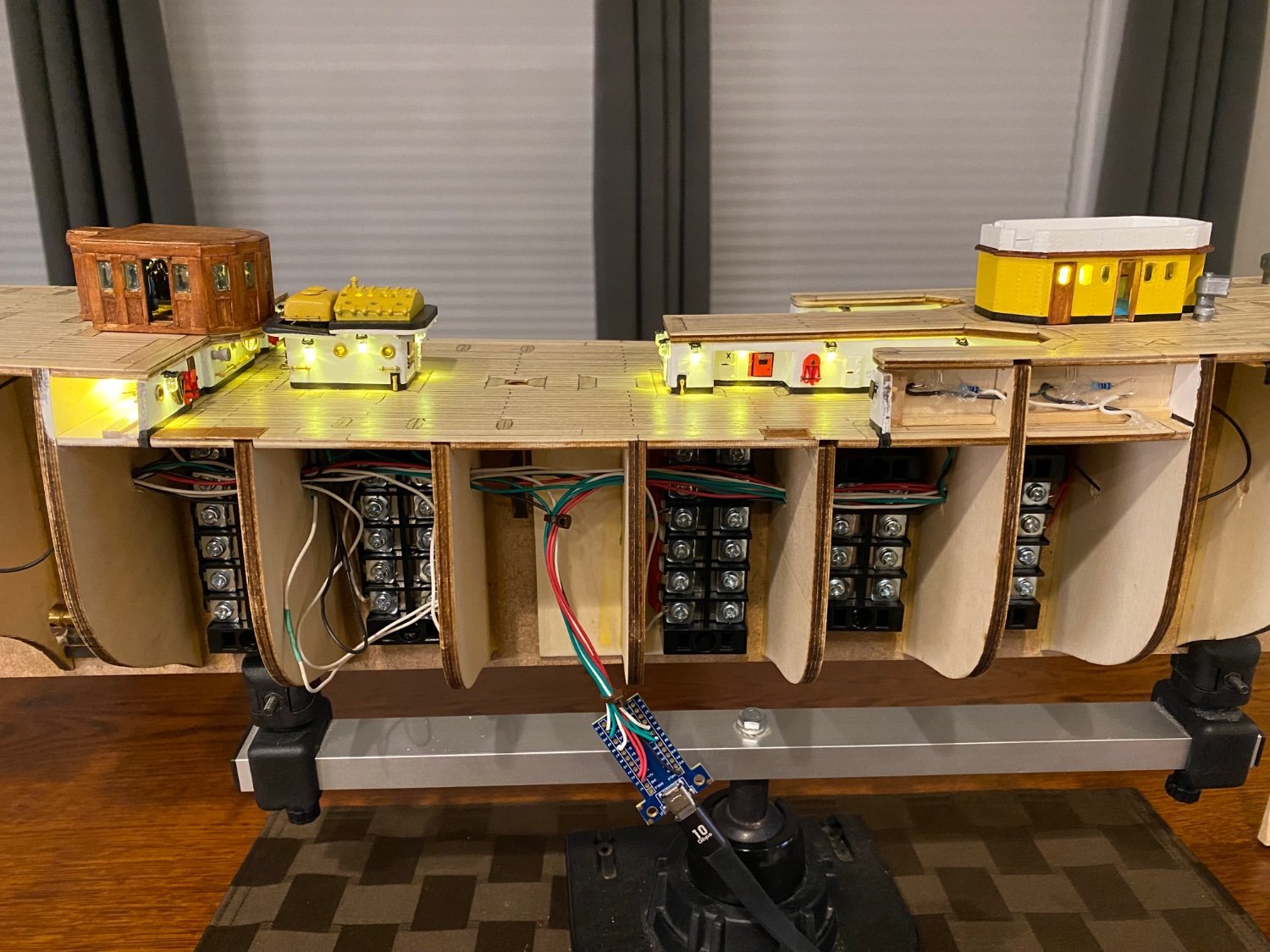
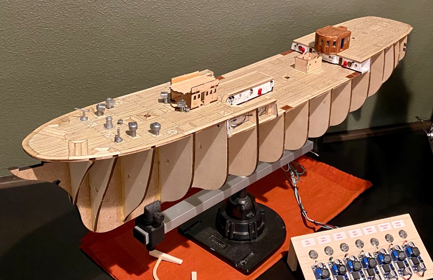
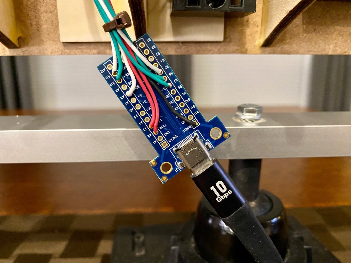
 Good evening mates, I finally took the plunge and organized the wires that make this ship work. I used some terminal blocks I had on hand to make the distribution bus, I know, a bit over kill but it’s the engineer in me. I purchased two usb-c terminal blocks, one for the ship that I will install along the keel which will be mostly hidden. The other usb-c terminal will be in the base. When this idea was first suggested, I was excited to finally have a clean solution to get the the power onboard. What I didn’t expect is that a standard high speed usb-c cable is not “straight through”, well, actually I expected the transmit and receive wires to be crossed, but the rest was unexpected. Not only is the cable wired differently if one swaps the ends, but also different when one flips one or both ends, making 6 different wiring combinations. Basically, I wired for only one of the six potential options, which means my cable will only work one way, if I swap the ends or flip one or both of the ends, it will not work. I will be marking which end of my cable goes to the ship and base respectively. With that done, my power cable is all working. Now to finish the lighting.
-
Mike, I’m not sure what doors you are referring to. I’ve not seen any images or other information that suggests any other access to the ship other than the two sets of stairs on both sides that can be adjusted to accommodate the sea wall they dock against which then allows access from the sea wall to the deck. Once on board, there are many water tight hatches to stairs leading to lower decks, several water tight doors into the fire control room, and ornate doors leading to officers quarters and conference rooms that can have a waterproof hatch placed over them in the case of heavy seas. On the other hand, I have seen images where some (or possibly all) of the portholes open, but this would not be for human access. I’ll keep my eyes open other hatches along the hull.
-
Good evening mates, another side marker update, both sides finished. Will get lighting working this weekend. Then on to the next lighting task.
-
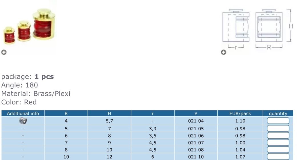
I’ll look and see, but as I recall I bought them from a store in California. I wanted a metal housing and when I called this place, the guy that answered the phone was very helpful, knew exactly the part I was talking about among the 100s of parts he had on his website, and answered my questions without hesitation. So I bought them from him and they arrived in a few days. They came with 12v bulbs, but not LED…but a clear 3mm LED fits nicely inside and looks amazing when lit. I looked at the RB Model link that VitusBering listed above, and it has the same ones I bought near the bottom, see image below. I bought the second one in the list as the inside diameter is slightly more then the 3mm LEDs I’m using.
-
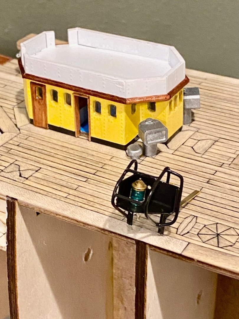
Good evening mates, here is the progress on the port marker and housing. I’m still not sure of the scale, but it seems close. Have to make a mirrored matching one for starboard side, prime and paint flat black…slow progress.
-
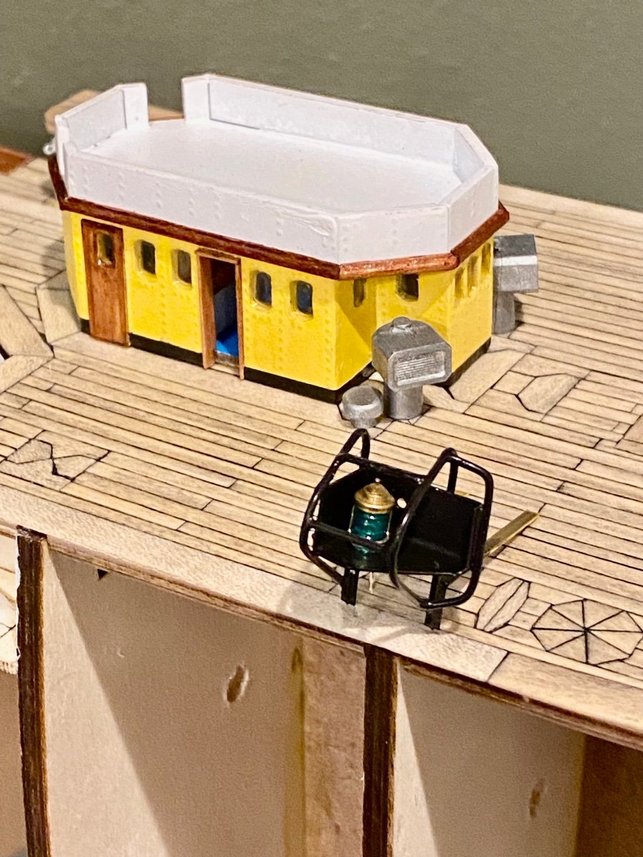
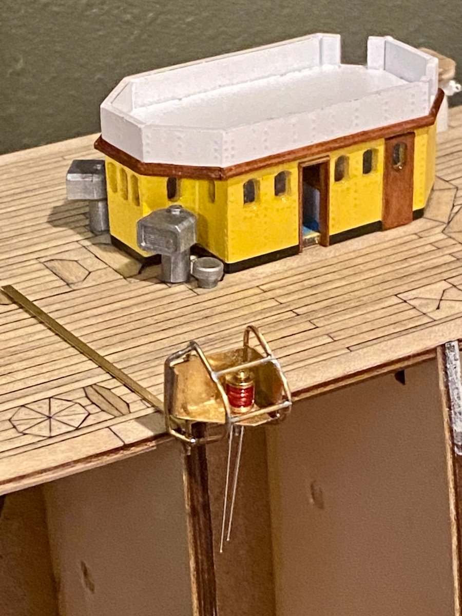
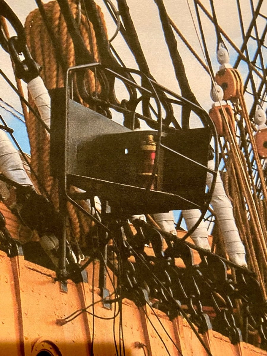
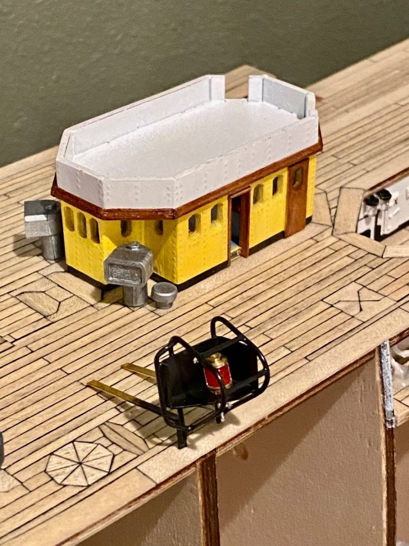
Hello all, I have a couple of updates, one of which I could use a little help. First, the last, for now, update on the chart room. Paint and lighting all finished, but still have to complete the second level. Next, I’m struggling a bit with the scale of side marker lighting. In the same image as the chart room is my second attempt, this one made in brass. I think I have the shape close, see second image of the real AV port marker and housing, but I’m not sure about the scale. I have no measurements or drawings, just building by sight and this image I found on line. Clear images of the side marker lighting are very hard to find. I only have two and this is the better of them. What is your opinion? Side marker look okay or a bit too big?

-
Good day mates, almost finished with the AV chart room for now, maybe tonight. Current state of affairs…this is the first time I have ever attempted to make moldings.
-
Good evening everyone, another update on the AV chart room.
-
VitusBering: somewhere in the above posts you made a comment something to the effect that any USC-C cable should work. After you came up with the idea about hiding a usb-c connector along the bottom of the false keel, I started to think that is what I would do, and will do. However, during my research, not all usb-c cables are the same. For example, if you get a power usb-c cable, it only contains 4 wires, the other potential pins on the plugs are not connected. Also, if you use a data cable, which you will need to use to have more then 4 wires, the cables are not connected straight through. For example, pin A2 (Tx1+) on one end will connect to B11 (Rx1+) on the other end of the cable, etc. For this reason, I will be using two circuit boards I listed above with a short data cable between them. Then I can map out, using a volt meter, a contact on one end to the correct pin on the other to make my entire system work. Using a usb-c connector on the base and at the bottom of the ship is a great idea! Just have to take a few things into consideration. Hope this helps.
-
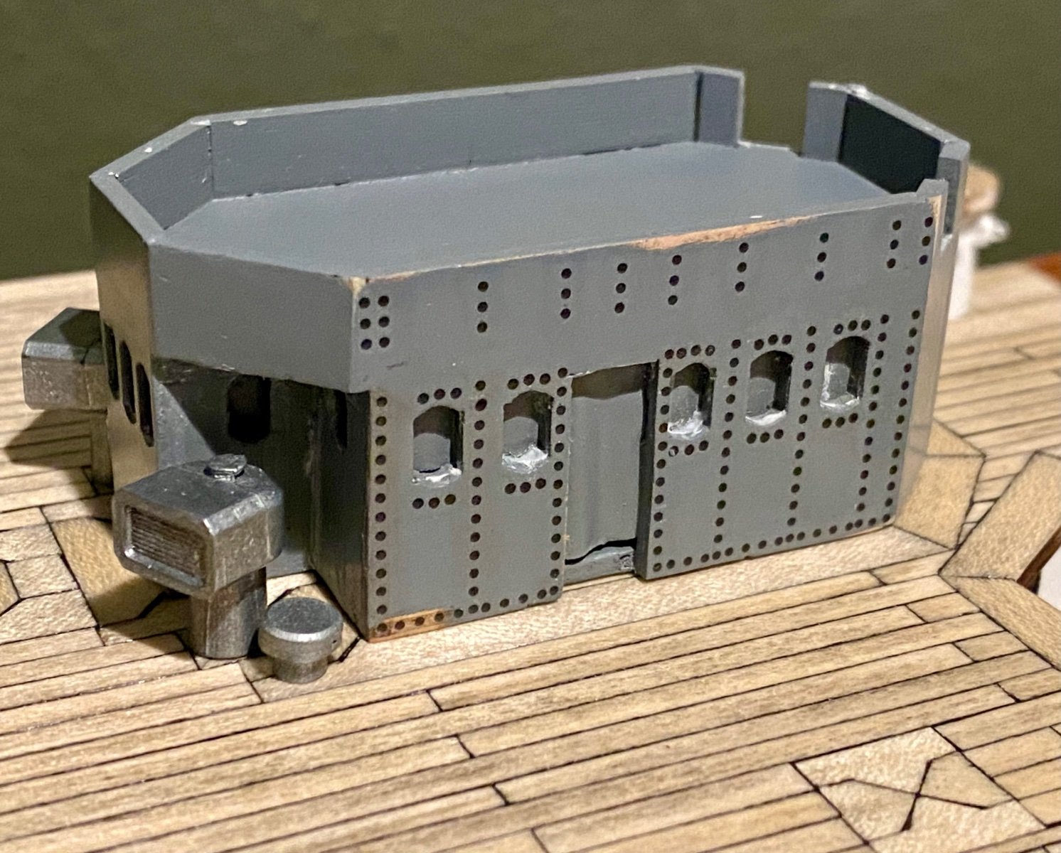
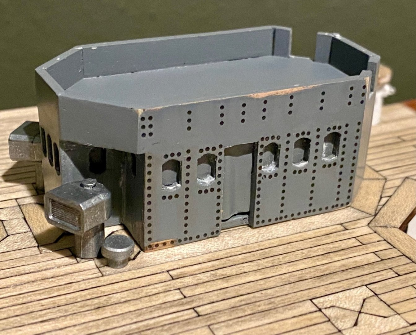
Good evening mates, I’ve been out of town for a few days so no progress…but this evening I did sit down and start the 3D rivet application to the chart house. These are 3D decals that are applied with decal set liquid and slid in place over top of the primed surface. Once the rivets are “stuck” and dried in place, a second application of fixer is applied. I’ll finish the other sides then air brush the entire structure in white followed by the AV yellow and then the trim. So much work for such a small structure.
-
VitusBering, I found a possible USB-C mountable solution at Amazon that might be easily mounted easy solder connections, at least for the female side of things. https://www.amazon.com/Type-Female-Receptacle-Breakout-Board/dp/B07771CFFM/ref=pd_bxgy_vft_med_img_sccl_2/137-8656501-6613113?pd_rd_w=5YN1B&content-id=amzn1.sym.26a5c67f-1a30-486b-bb90-b523ad38d5a0&pf_rd_p=26a5c67f-1a30-486b-bb90-b523ad38d5a0&pf_rd_r=E6MH61KVDG3QVJ9DAMFM&pd_rd_wg=WIG8G&pd_rd_r=bda83ae7-cbce-462b-8ddb-cbc7ee577fbd&pd_rd_i=B07771CFFM&psc=1
-
VitusBering, I think that will work for me just fine. Thank you for the info!
-
VitusBering, well…to be honest, I’m still looking for something. I need 9 contacts for my lighting plan, so even an RJ45 is too small. I like your idea of the usb-c connector. If I’m not mistaken, that supports 24 contacts/wires. Where did you find both the male and female ends? Did you find the actual bare connectors or did you find a cable to splice in?
-
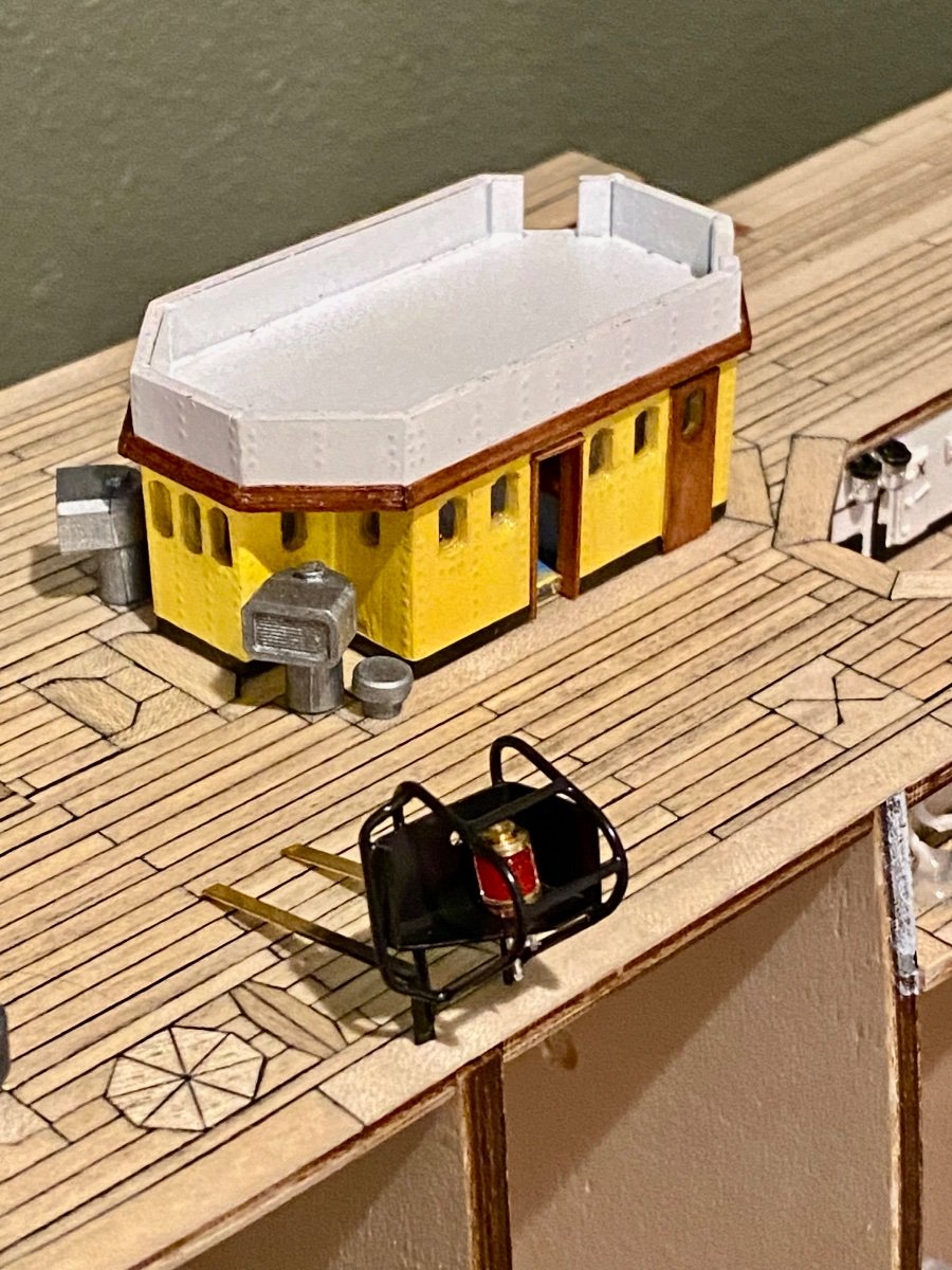
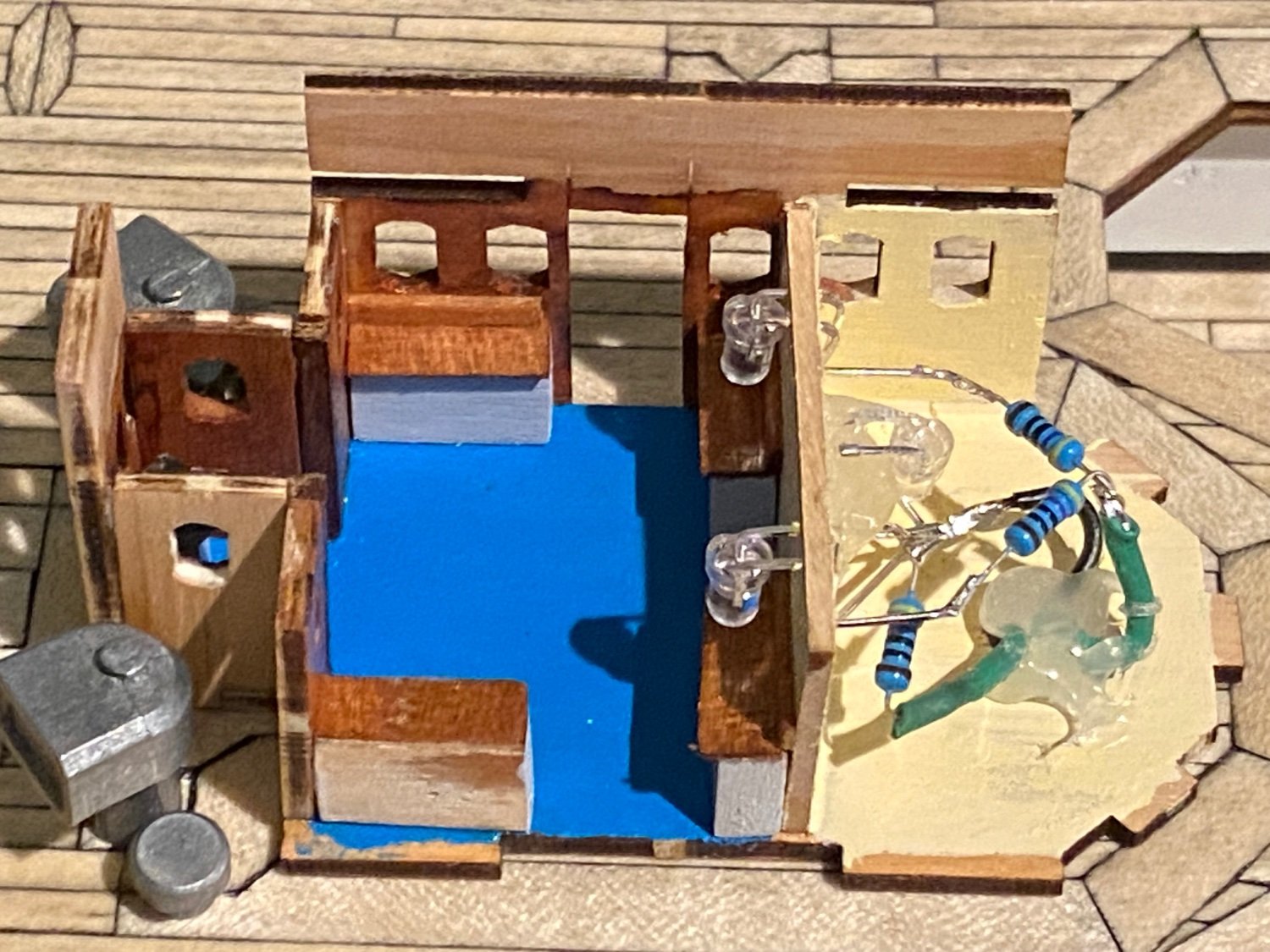
Good evening mates, this weekends build is all about the last deck structure located on the foredeck, the chart room. OcCre did a number on this structure, it was never meant to have fixtures installed inside as the walls have to be installed at the same time as the ceiling/deck of the upper floor. Also, I had to do some filing on the windows as OcCre made them rectangle and they should have a curve on both the top and bottom. This would have been so easy to have built in with the laser cutting, but they didn’t. 😞 The lights for this structure will be two fold, the chart room will come on with the deck lights while the storage room, the aft 1/3 of this structure, will have its lights come on with either of one port hole switches or the second one or both. I hope it will be a nice touch. The chart room consists of a bright blue floor, four chart storage standing desks with glossy wood tops, wood stained interior and almond white ceiling and aft wall…all matching the real Amerigo Vespucci.

-
Good morning JeffC, I bought mine from Ages of Sail out of California, but they are an Amati product (AM4090/05) you can probably get from many places. https://www.agesofsail.com/ecommerce/fittings/rigging-fittings/deadeyes-chainplates/amati-chainplate-with-deadeye-5mm-am4090-05.html
-
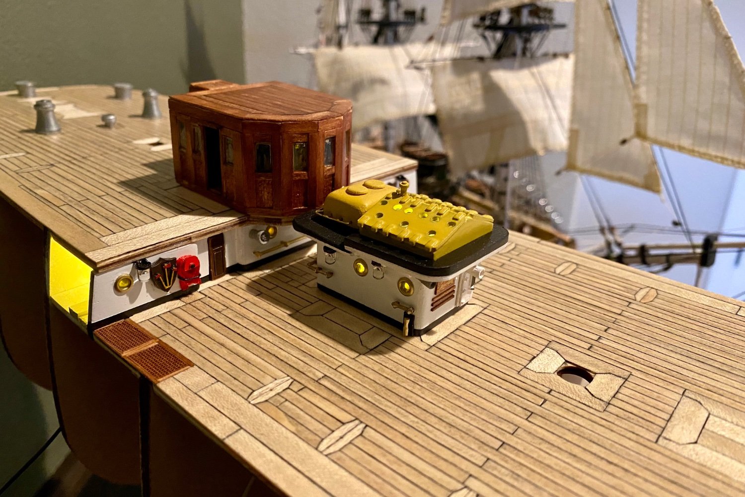
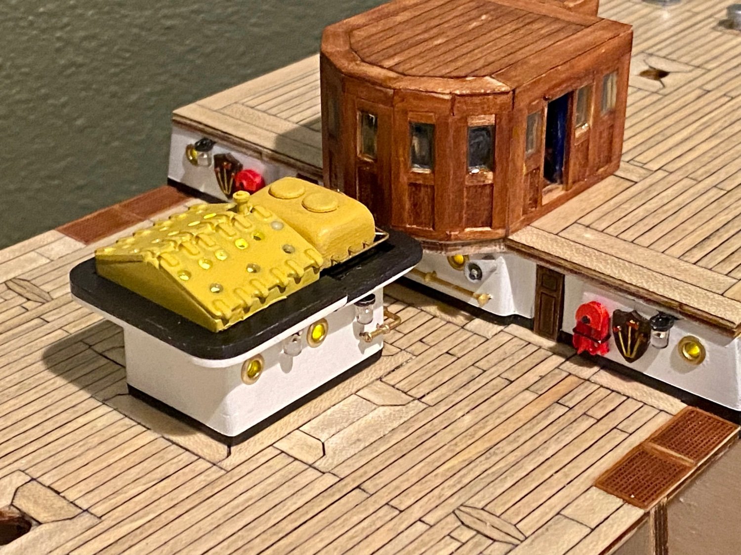
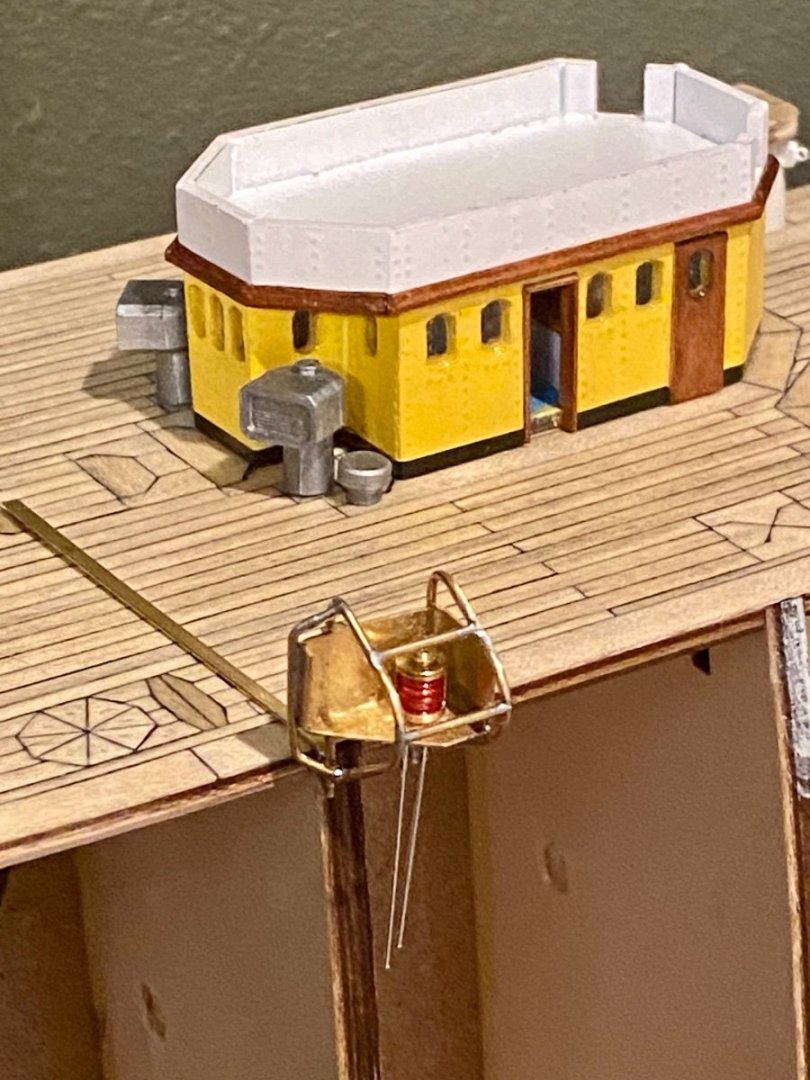
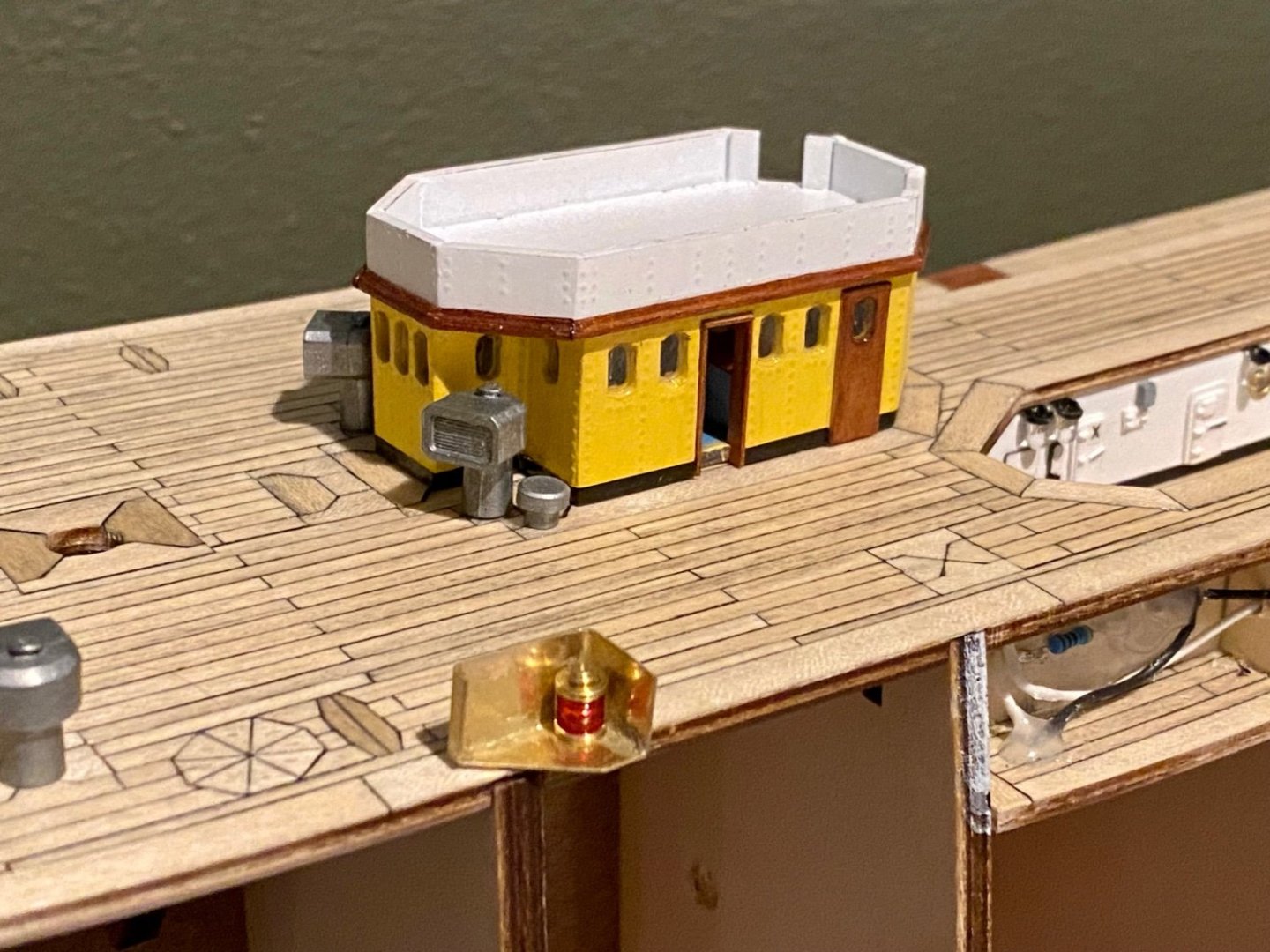
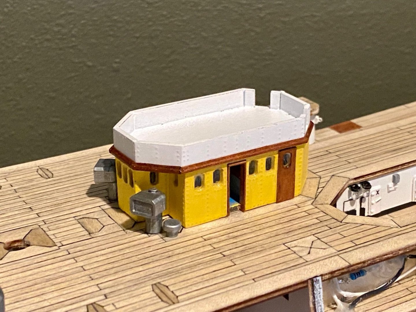
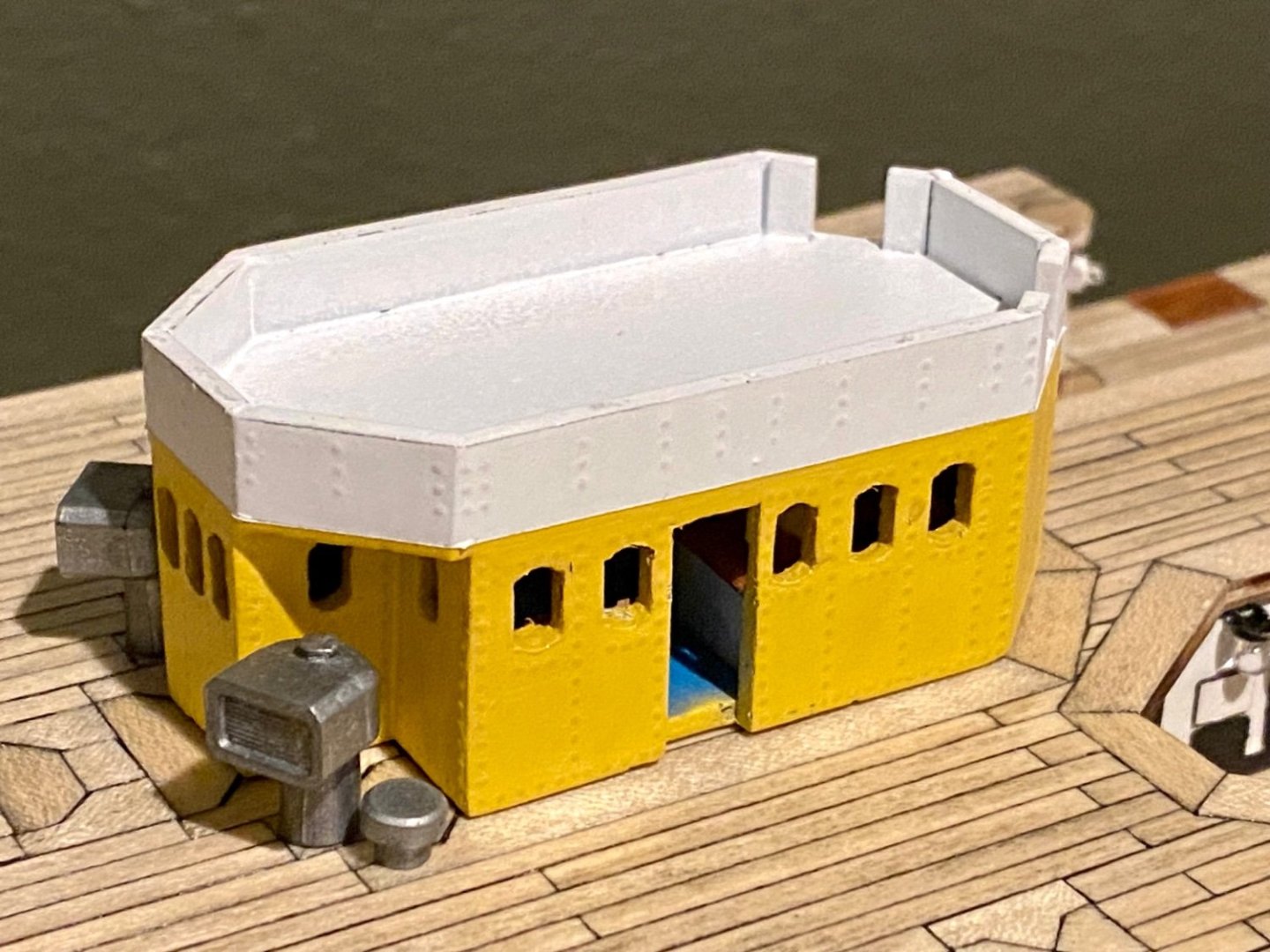
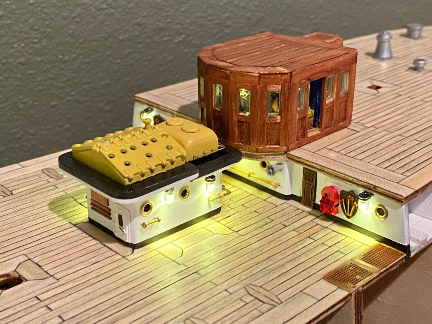
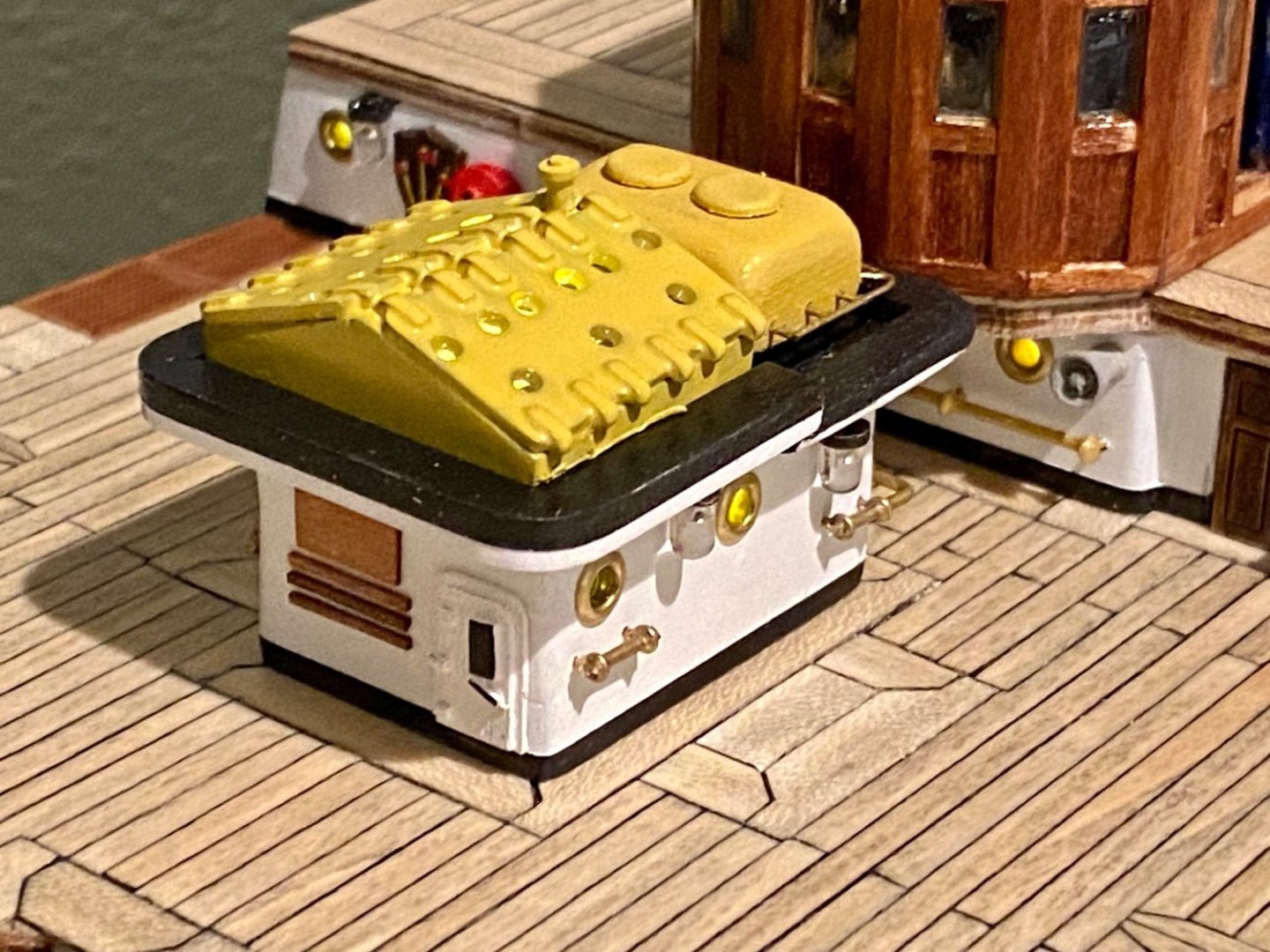
Good evening mates, well, I think this will be the last update for this structure on the main deck as I think I’m finished enhancing it over the stock kit. For starters, this structure is only temporarily installed on the deck, but an important build at this time for the added lighting, both inside and out that needs to be working before enclosing the hull with planking. Besides the lighting, other enhancements include signage, improved railing, window glazing for the port holes and the skylights, added the door, added roof supports, megaphone speakers, and several paint adjustments to make it look more like the real AV.

-
Mike, I've been looking at the hull, starting to think how I plan to paint everything. To me it looks like a satin, not really glossy but not matt either. I'll probably paint with what I have and put a satin clear sealer on everything. At least, that's my plan for now...subject to change.
-
Good evening mates, here is a mid week update. More detail on the main deck structure.


-
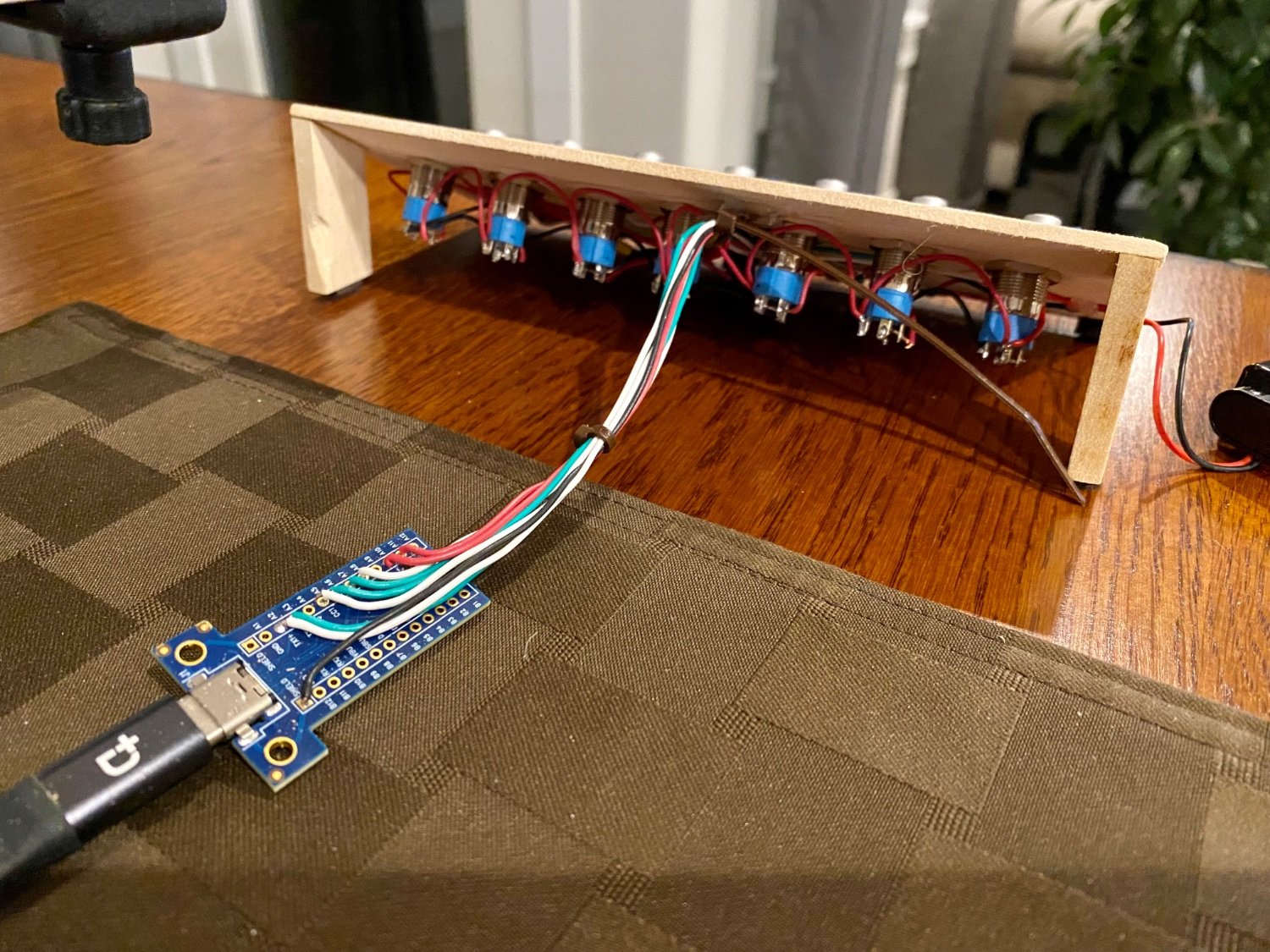
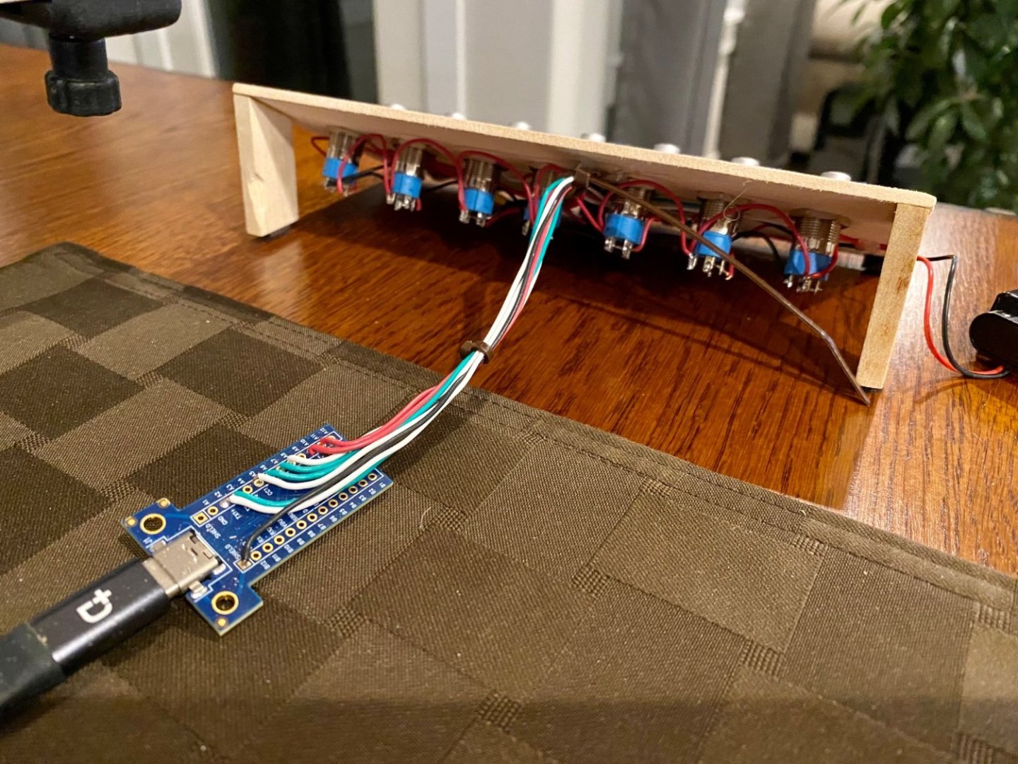
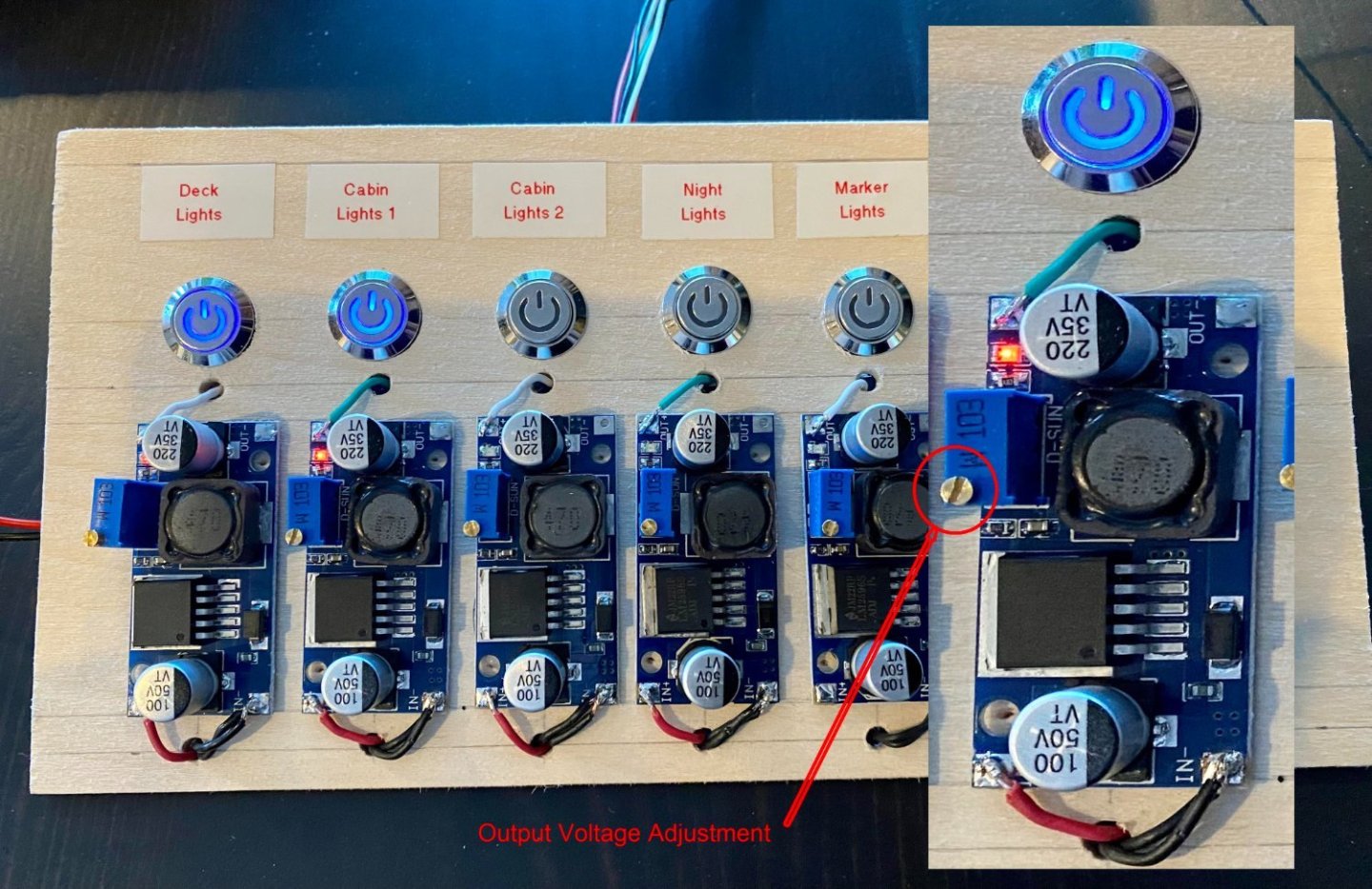
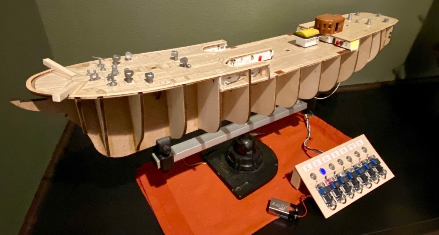
Good morning VitusBering, The voltage regulators that I used I purchased from Amazon (https://www.amazon.com/dp/B09L49XQYD?ref=ppx_yo2ov_dt_b_product_details&th=1) specifically because each regulator can tolerate up to 3 amps and is adjustable from 1.5v to 35v with an input capability of 3-40v. Currently I'm running everything on a single 9v battery, but in the end all of the regulators will be built into the stand and plugged into a 3 amp 12v power brick. As it turns out, I love the adjustability of these regulators because I am able to easily adjust the brightness of each channel, so the deck lights can be turned down to a dim illumination. I use 3mm 1.8-2.3 volt various colored LED's with resistors that came with the LED's matched for 6v running voltage for full brightness at 20mA. I'm currently running my deck lights at about 3 volts, enough to turn on the LED's but allowing them to be dim, just to cast enough light that the viewer is able to see that the lighting works. My calculations indicate that I should be able to run about 150 20mA LED's on each regulator, but in reality, I'll cap out around a 200 LED's total for the project across several regulators. I hope this helps! UPDATE: More helpful information (I hope)...The output voltage maximum will be 1.5 volts lower then the input voltage. For example, an input voltage of 9v, as with a standard rectangle battery and the way I have it running at the moment, the maximum output voltage will be 7.5 volts thus making the adjustable voltage regulator operational from 1.5 to 7.5 volts in this configuration. My final version will be operated from a 12 volt 3 amp power brick, thus giving my operating output range from 1.5 to 10.5 volts. Since I'm rigging my ship to run on 6 volts, all the 3mm LED's and the 6 volt motor for the propeller, this adjustable voltage regulator works perfectly. Given these specs, I can run a total of 400 LED's at full brightness (@ 20mA) and the 6 volt motor all on a 3 amp power brick. With my newest projected configuration for the lighting of this project, I anticipate around 200 LED's and the 6v motor...which allows for some power to spare. However, I really don't think everything will be on at the same time, but it could! Final bit of information, if anyone is interested...Below is my temporary control panel which allows easy access to the output voltage adjustment. When finished and the voltages all set for the final model, I will build them all into the stand with just the switch visible with a nice description tag. Currently planned, 1) Deck Lighting - all the outside visible lights, mostly on the main deck, 2-3) Cabin Lights 1 and Cabin Lights 2, my plan is to be able to have two sets of port holes light up, one set with scattered lights or compartments that will have a realistic look of some port holes lit while others are dim, and the second set just the opposite giving me the ability to choose one or the other, or both to have all the port holes lit, 4) Night lighting which is what the Amerigo Vespucci is famous for, the Green, White and Red deck lighting that casts colored light up into the masts, 5) Marker Lights, you guessed it, the red (port), green (starboard), white/amber (stern) and the white lantern that sits on the Mizzen boom, 6) Emergency lighting - only a single red and a single flashing red emergency lighting located on the main deck (unless I discover that more exists on the AV), and last 6) the motor which is in the bowels' of the ship and will turn the single propeller at about 35 rpm, about 1 revolution every 2 seconds, really quite slow but don't want to injury someone. Well, that's the plan...we will see how it goes, but so far, so good.
-
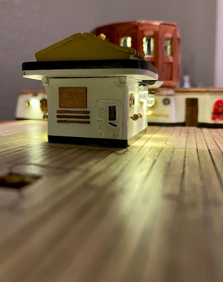
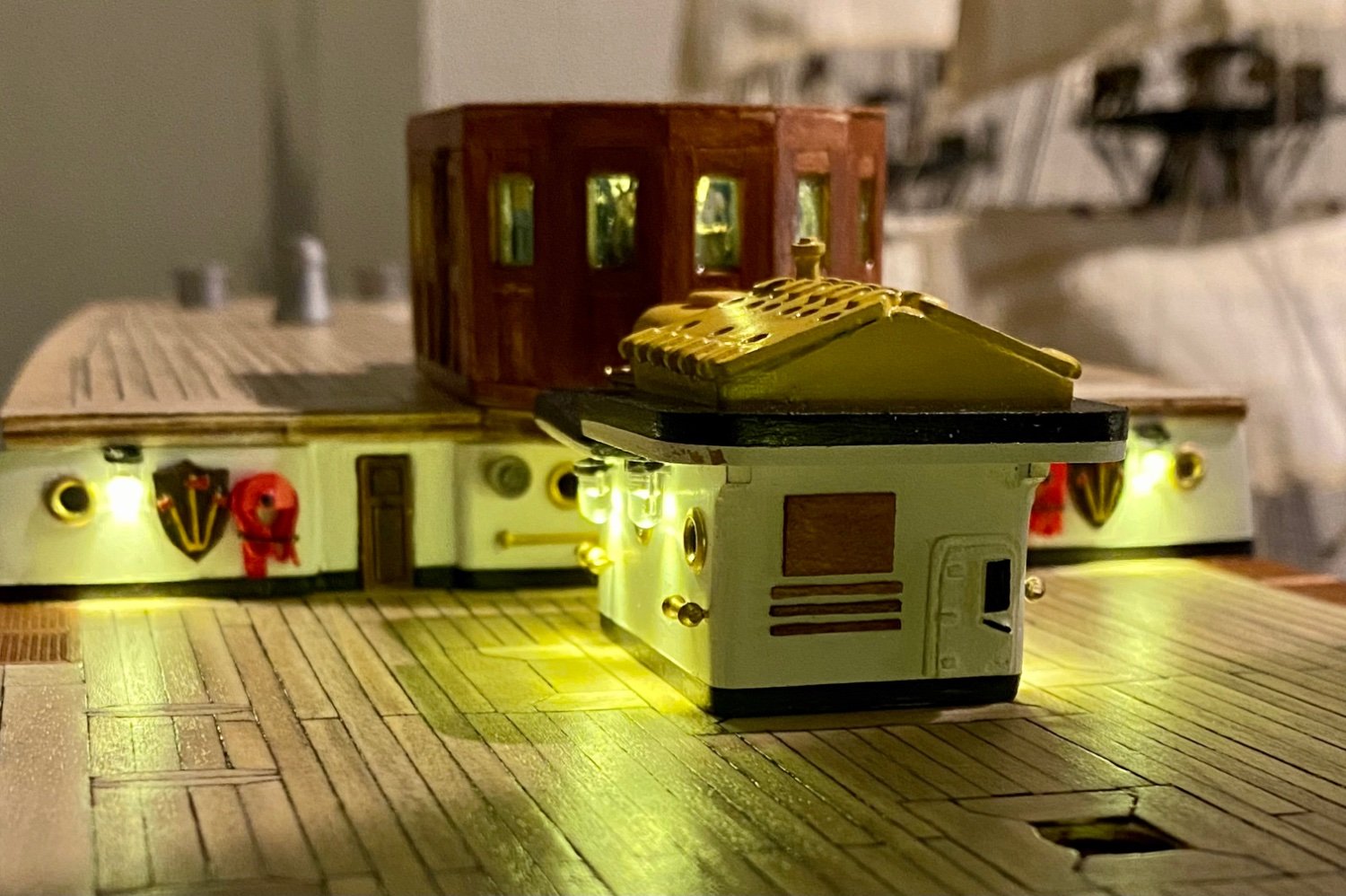
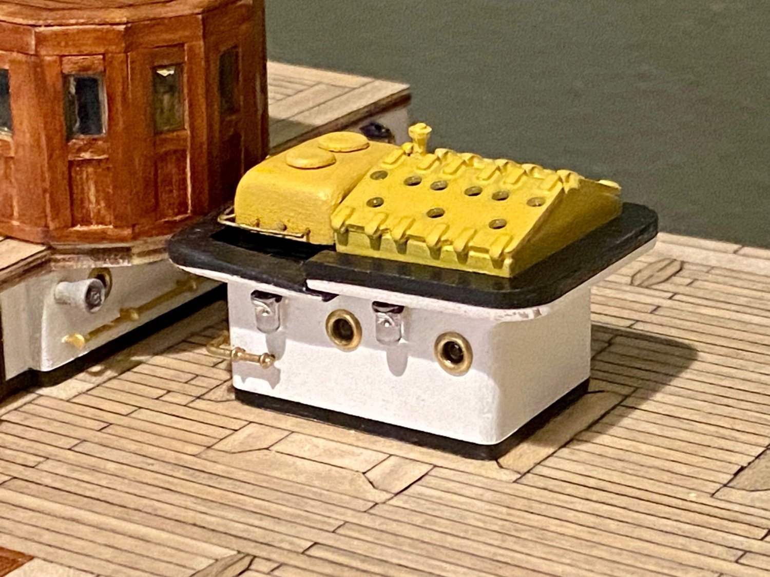
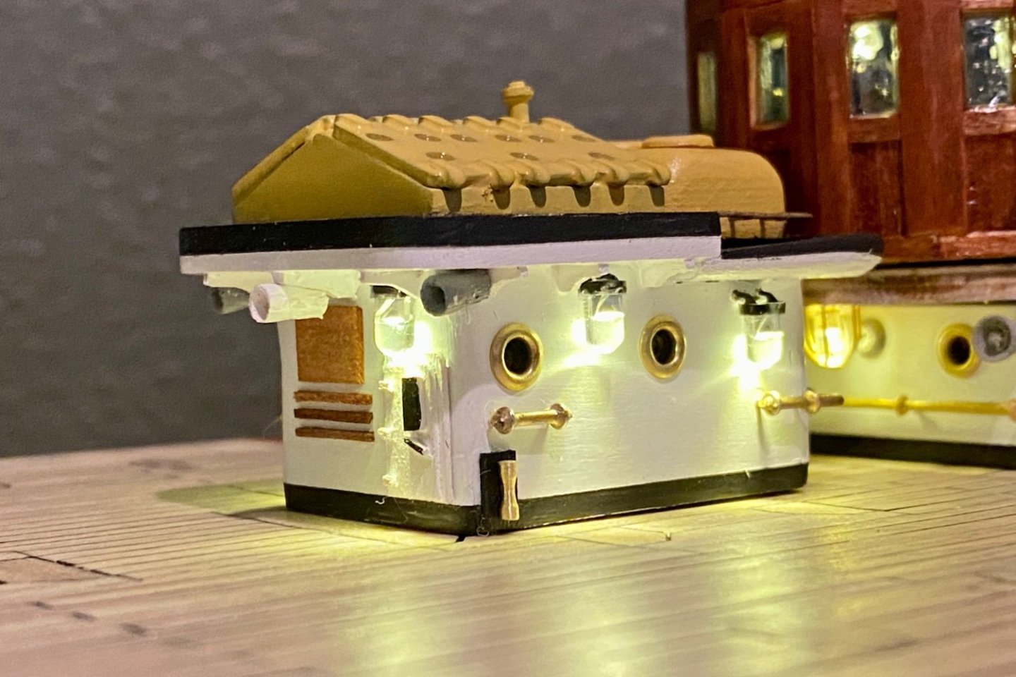
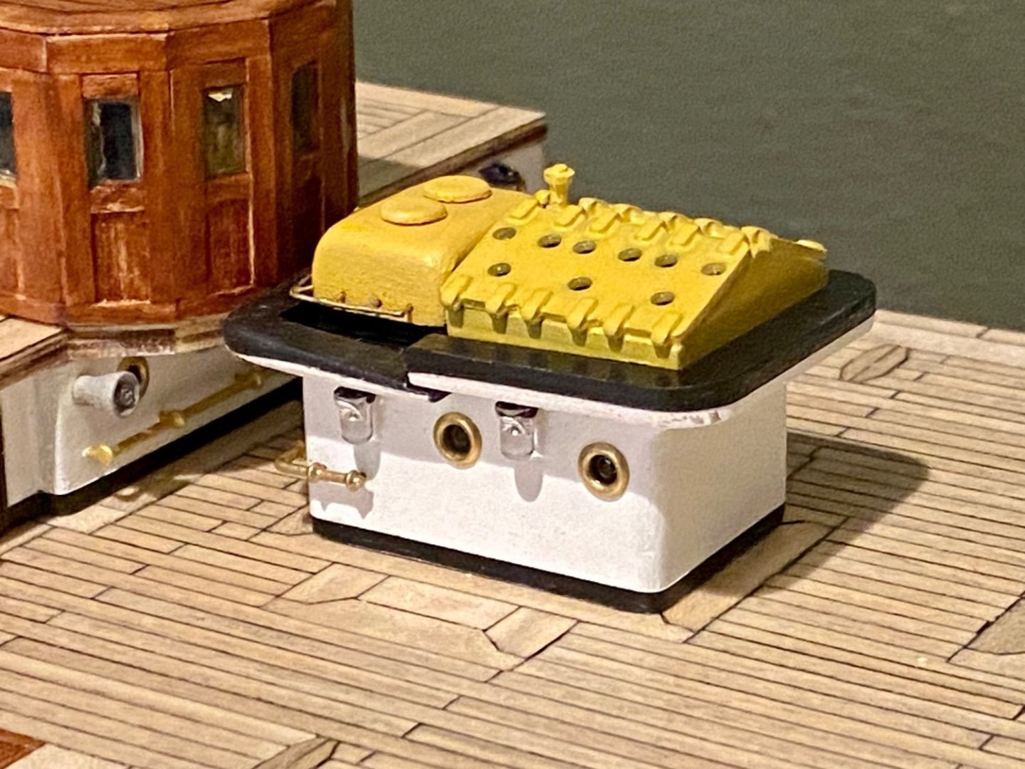
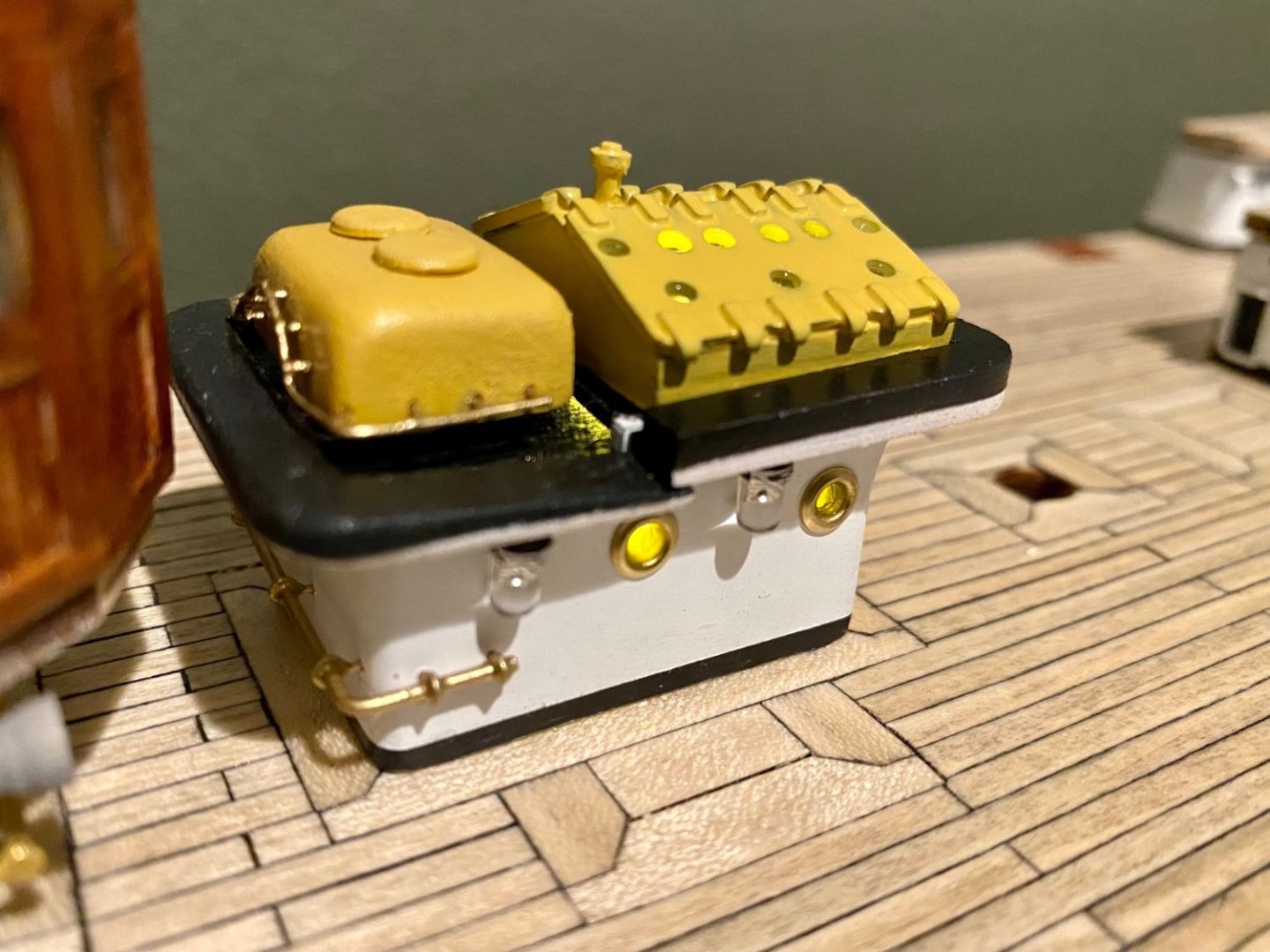
Good evening mates, time for an update. This weekend I spent time with more lighting. This time on the small structure on the main deck. This structure is only temporarily placed, but I have everything working. Also, while impossible to see in any of these images, I installed the window glazing on all the port holes and skylights (not sure what the nautical name is for these) of this structure. Just a little more work to do and this one is finished.

-
Mike, I'll keep that in mind. Right now I'm so far away from planking...I have so much more lighting to get finished, but now that the deck is completed, there should be rapid visual progress forthcoming.
-
Well, I guess this is a personal decision for the AV. Since it has a metal hull, our attempt is to plaster the wood and make it look like metal. So a second layer is probably not necessary. I’ll probably add the second layer because the two other models I built, some areas sanded to get a smooth finish thinned out making the wall somewhat transparent with bright lighting inside. So I was glad to add the second layer. Not sure how this one will turn out.
-
Mike, the equipment is only temporarily mounted, with a 1mm rod mounted into the bottom of each piece and drilled into the deck. Just a little twist and the pieces come off. I won’t have them in place when doing the planking. I have lighting that I need to place, not in the way of the equipment, and I have to have lighting and wiring all working before doing the hull as once the planking is done, no more access to the wires.
-
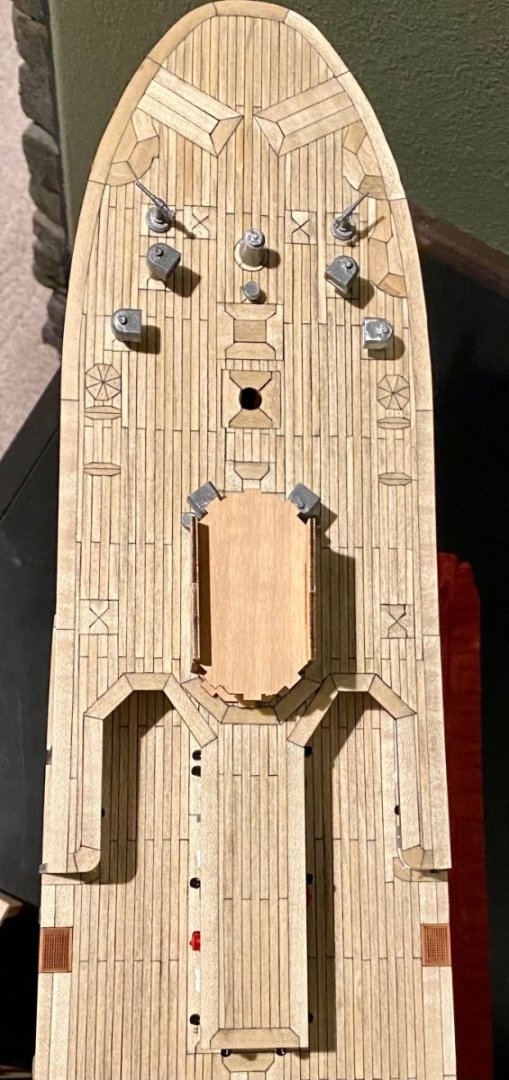
Good evening everyone, it’s been a while since my last post. This week I was working on the fore deck with all the extra Amerigo Vespucci inspired inlay. I’m happy with the final product and started to temporarily place the deck hardware. To hold each piece of equipment in place I’m adding a 1mm post to the bottom each piece and drilling a hole in the deck for placement. So far, it’s all working well. Thanks for spending a little time with me on this journey.