Ras Ambrioso
-
Posts
662 -
Joined
-
Last visited
Content Type
Profiles
Forums
Gallery
Events
Everything posted by Ras Ambrioso
-
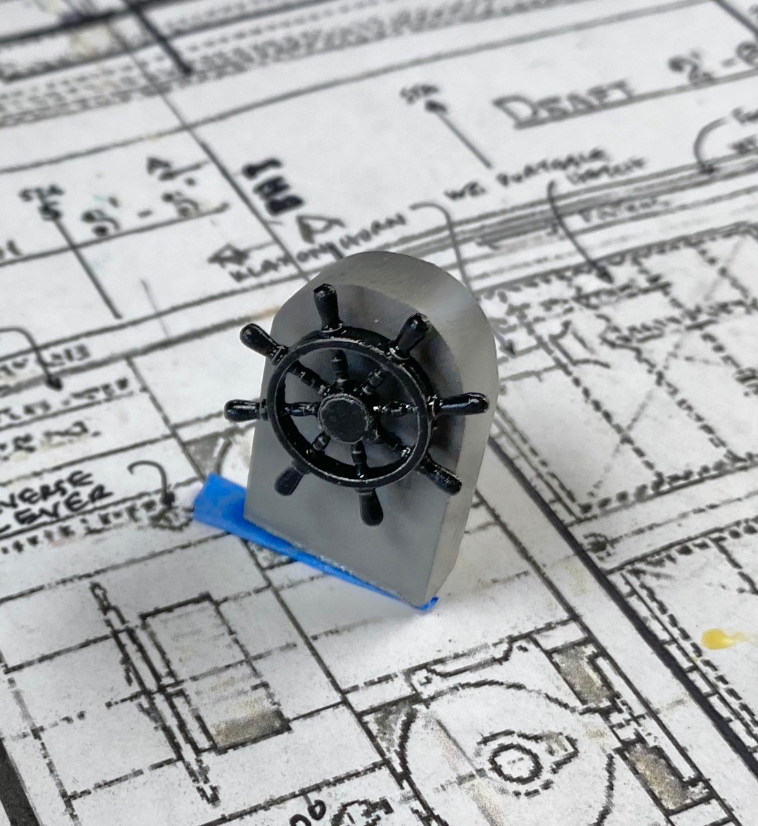
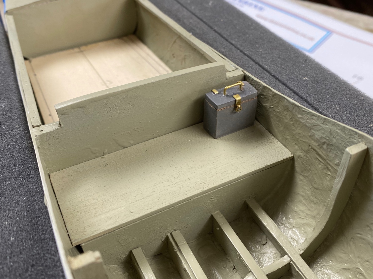
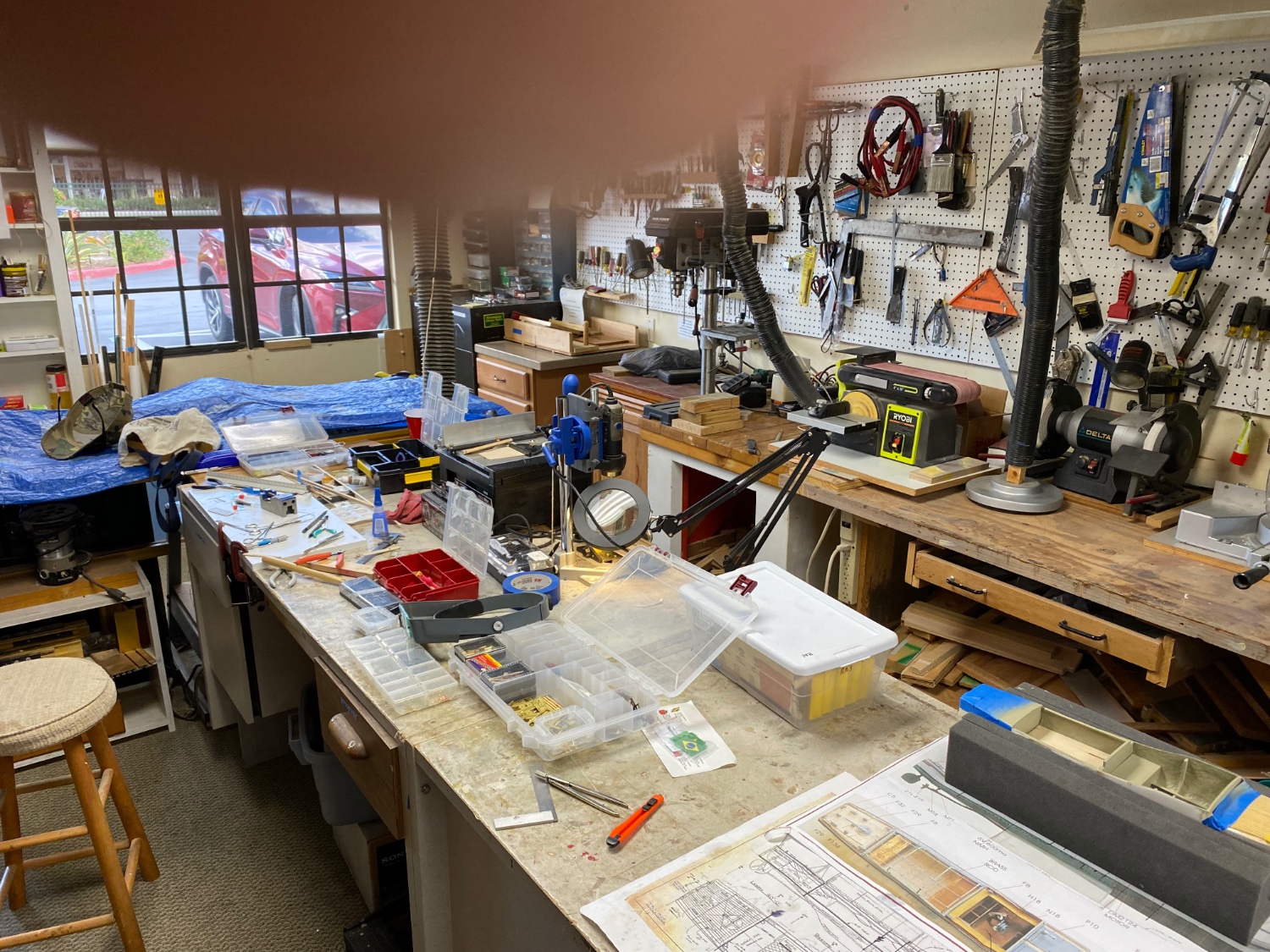
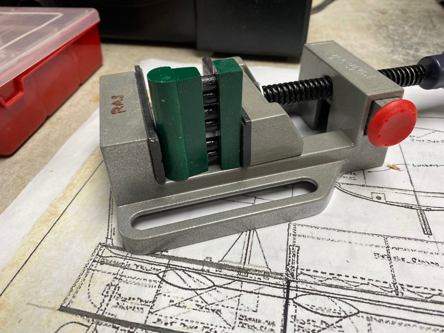
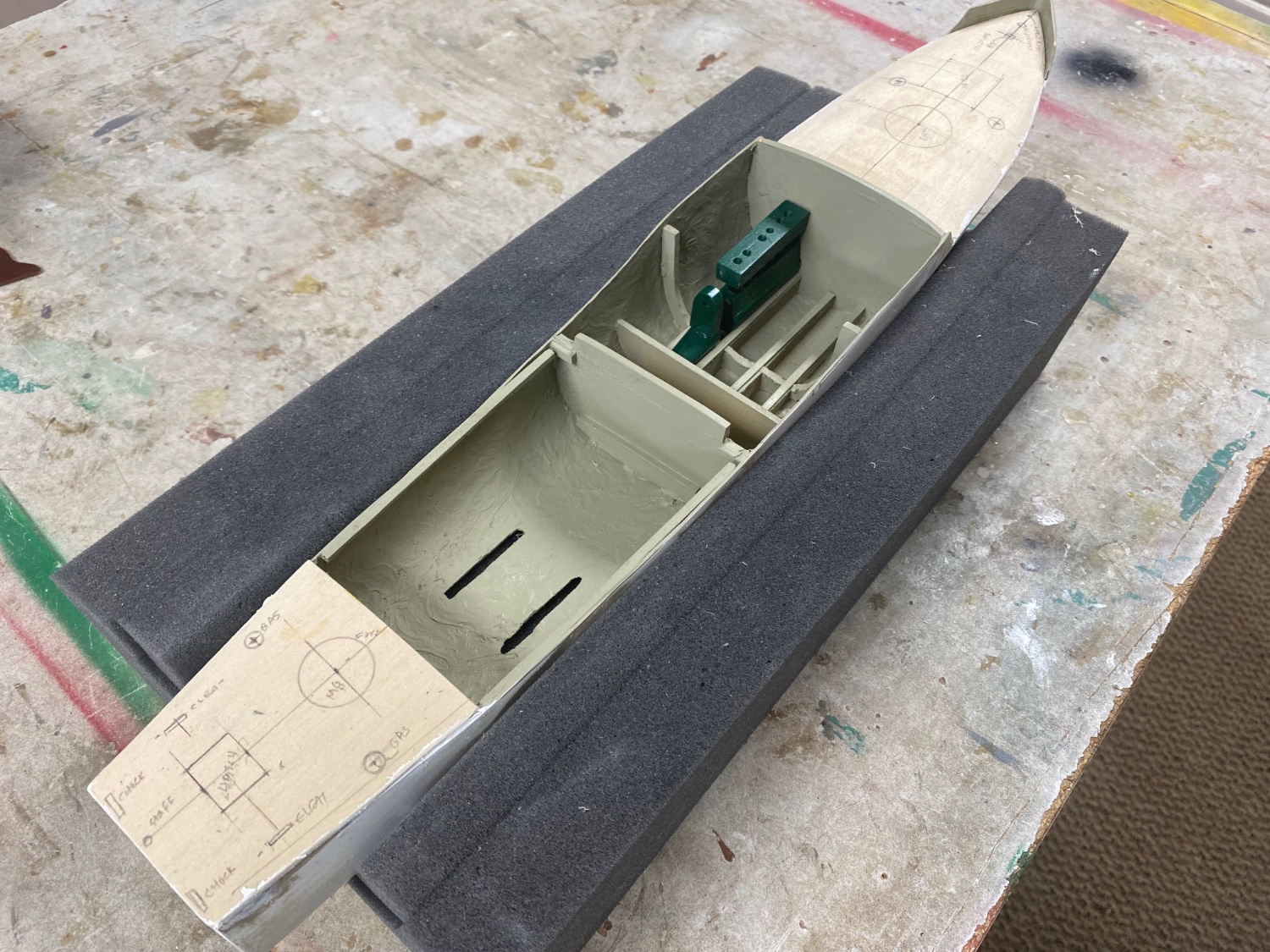
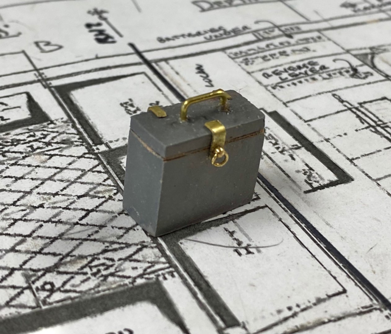
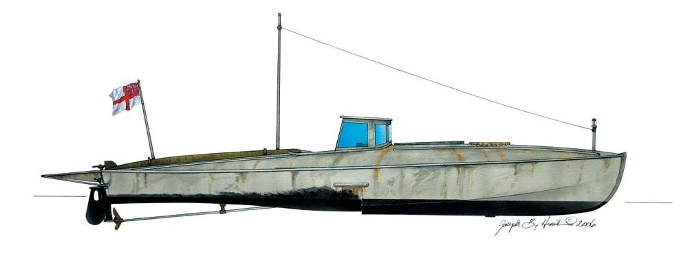
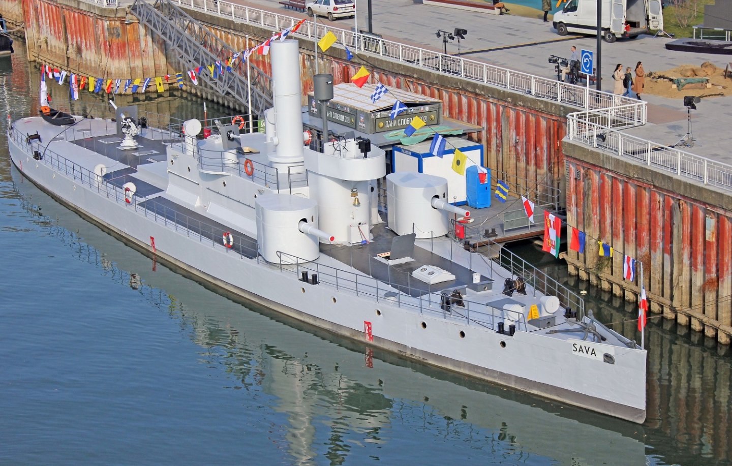
 Making slow progress as the Admiral is out of town and I have to handle a few household "honey do's". I have concentrated now on finishing the cockpit. First was the helm that was a fairly easy job as I am using the supplied metal part. I did a lot of cleaning on the wheel and following is the result. I am still in the dark about the rest of the required engine control instruments for this boat. I assume they should have had a compass, throttles for both engines plus oil and gas gages. I would appreciate the input of the forum on these items. I have fabricated the ammunition lockers (no pictures yet) and last but not least: a tool box. This is the look of my shop while making the tool box. Amazing use of the space for such a minute part. LOL Next, I am thinking of making the cabin roof removable so that we can all admire the engines. After that is done, I will start my favorite subject, that is, making the guns for this little warrior. This experience has been like candy to my thoughts and I am already looking at my next projects and haven't decided between two subjects: the first one is a World War One Austro-Hungarian Danube river monitor and the second is a WWI British Costal Motor Boat (CMB) torpedo boat. Maybe, I will build both. Thanks for following.


-
I am getting ahead of myself. Haven't finished the Mimi but looking forward to future projects. A couple of years ago I bought the Zvenza kit of the Borodin. Now by following these MSW posts I have gotten acquainted with the extra details that are possible by using PE parts. In my research I came over you post and I love dit. I am also following your U-9 model that I consider the best plastic model presentation of a a submarine. Thanks for such great models for us to drool.
-
Phil, thanks for your quick reply I will be following your posts. Amazing the work that guys like you, Valeriy, Wefalk, et al, do to our hobby. Thanks again.
- 54 replies
-
- 2
-

-
- 3d cad
- cleveland class
- (and 1 more)
-
This last session feels like I am attending a class with the best professors sharing their knowledge. Thanks Valeriy, tell me what is forosho cutter.
-
From your reply to Valeriy I found your post. What an amazing job collecting all that information. I have used the Archives before but mostly for general arrangements. I will be following your build in one of my future projects that is a Sumner class destroyer USS John W. Weeks (DD-701).
- 54 replies
-
- 2
-
-
- 3d cad
- cleveland class
- (and 1 more)
-
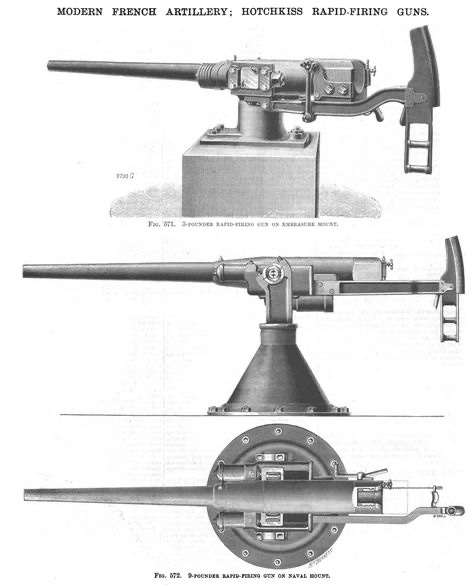
Beautiful guns. They look nicer than my Amapa’s and mine is at 1/64. And, by the way, I also missed the firing pistol.
-
Found your log toor late to follow it. I love you attention to detail. Also the discussion about the minesweepers were very interesting. Witing to s follow your next build. Great job, thanks.
-
My knowledge is increasing exponentially since I joined this forum. I just learned a lot about cuttle fish bones on wikipedia. Amazing bones. Thanks Mark.
-
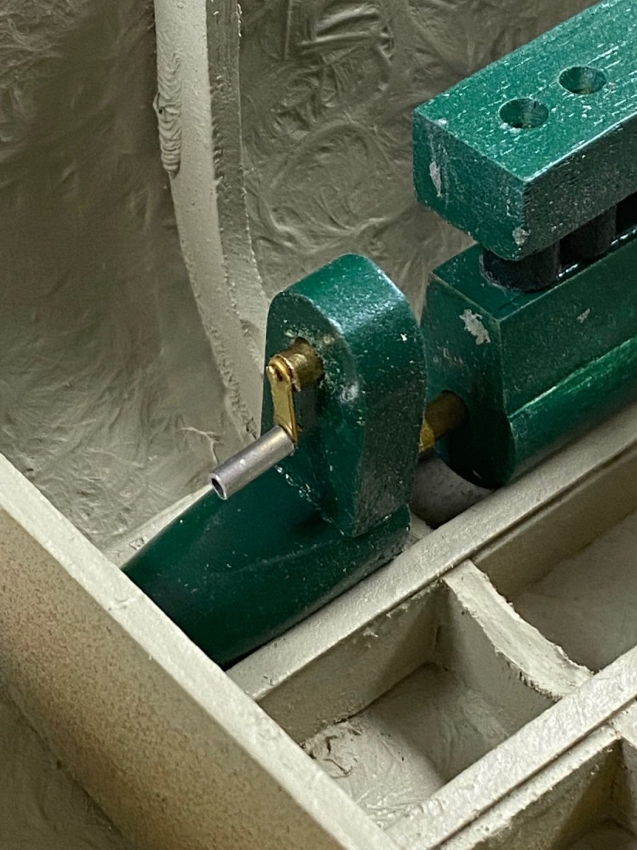
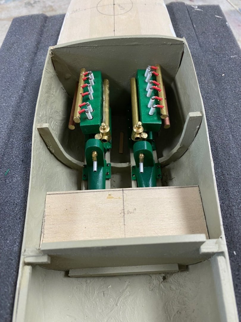
After my catastrophe with the carburators I changed the design to a front mounted carburetor feeding a straight down manifold. It worked. The engines still need a little dressing up but for all purposes I considere them finished. They will be put aside until I finish the engine room and cockpit. The next item are the gear shift levers that will stand at either side of the helm. These were provided in the kit but following my desire to scratch build I tried to develop a simile. Next I am going to tackle the helm itself. For this one I feel I will use the steering wheel provided in the kit. With the engines completed I worry about the remaining controls: throttle, choke, and the instruments: RPM, compass. Based on the models I have seen there were very few accessories to run these engines. We will see what comes to my old brain.

-
Wefalk, thanks again. Bewitched was one of my favorites back then. Look my next post for the results of the "nose twitching". Graham, thanks for your advise. I never heard of cuttle fish (calamari) bones being used on anything. Learn something every day.
-
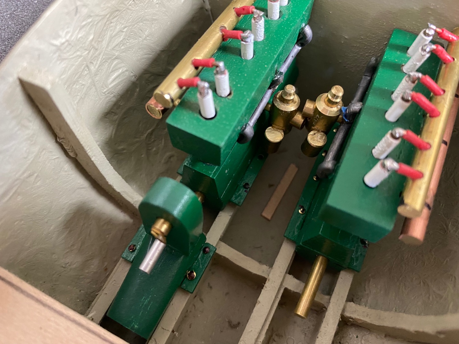
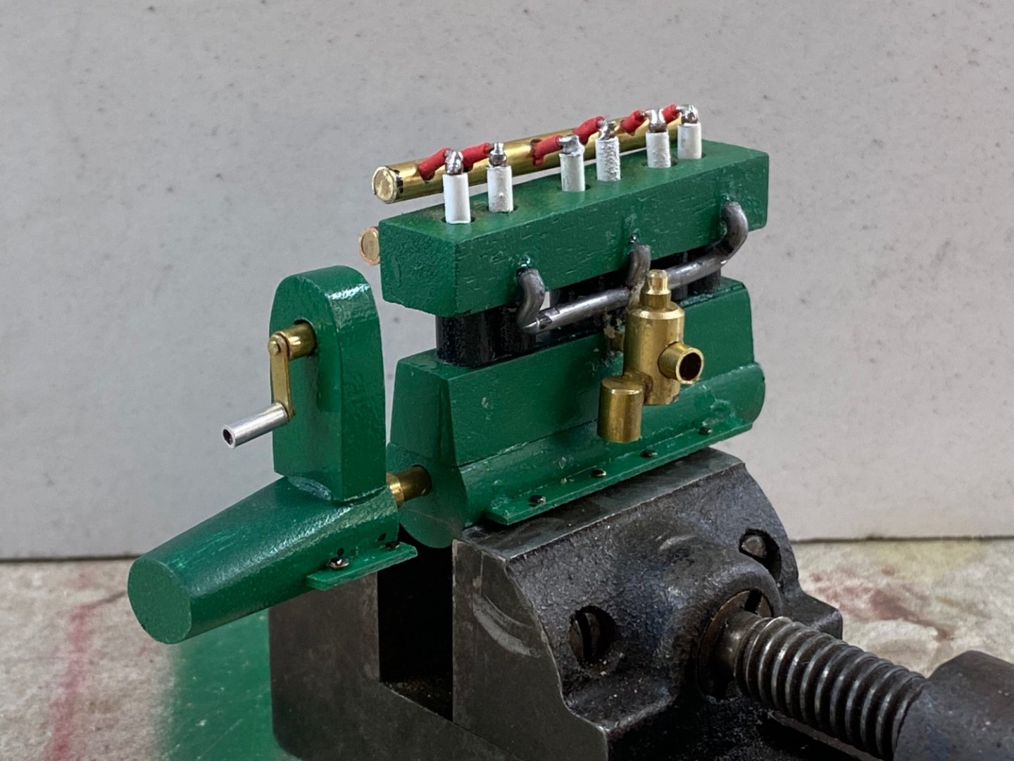
Well, when you are scratch building it means you have to scratch your head several times to decide how to build something. For this project I only had one sheet with the general layout and three cross sections of this boat. Deans Marine offered a kit at the scale I had selected for the model with a molded hull in styrene (?) and the materials to make a R/C model in plastic. I decided to use the hull and scratch build all the details. One my interests was to build the engines and, after a failed research, I used the information on the cross sections, several inquiries on google, and my engineering background to come with an acceptable looking simile. So far so good. No where I could find what to do for the carburators since I had assumed that a "petrol" engine requires one. I figured that a 100 HP the engine would need a carburetor with at least a 3 Inch throat. I remembered, back in my youth, my dad had an MG-TC with a beautiful set of SU carburators. So I decided to do SUs for these Thornycroft engines. And this was the result I developed an intake manifold (see post #22) and also fabricated an exhaust manifold. This is how the port engine looked after I finished. Boy, was I pleased! I went on and built the second engine making sure that the new engine was an starboard engine. Then, another catastrophe. There is barely any space between the engines to fit my contraptions. The drawings indicated that both engines were identical but the engineer in me saw that there would be no way to service these engines within the space between the engine blocks and the hull so I figured that a RH-LH arrangement would work. Also, as I noted before, the molded hull is about 1/4 inch narrower (6 inches in the actual boat) than the drawing sections shown thus limiting access even more. Scaling the actual space available between the engine mounts came out to only 12 inches available access for service. The fact that the roof of the engine room has two huge hatches led me to believe that the intention of the builder was to remove the engines for any service and that would have been very difficult by the shores of lake Tanganyika. My solution now is to redesign the intake manifold and relocate the carburators to the front and lower side of the engine. I am so much fun. LOL

-
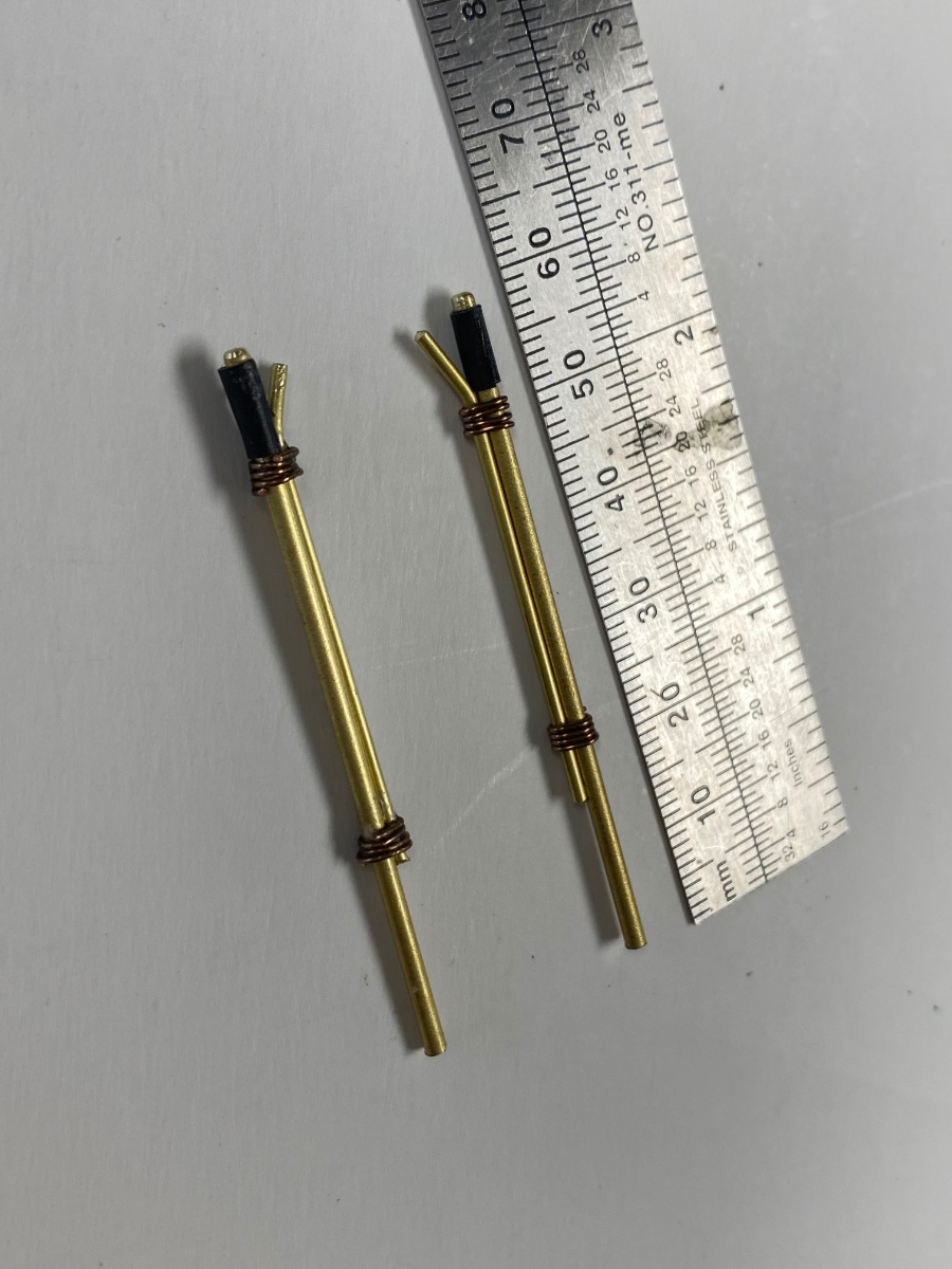
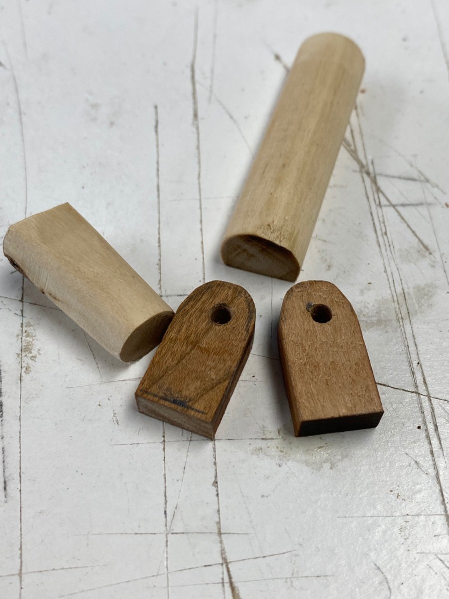
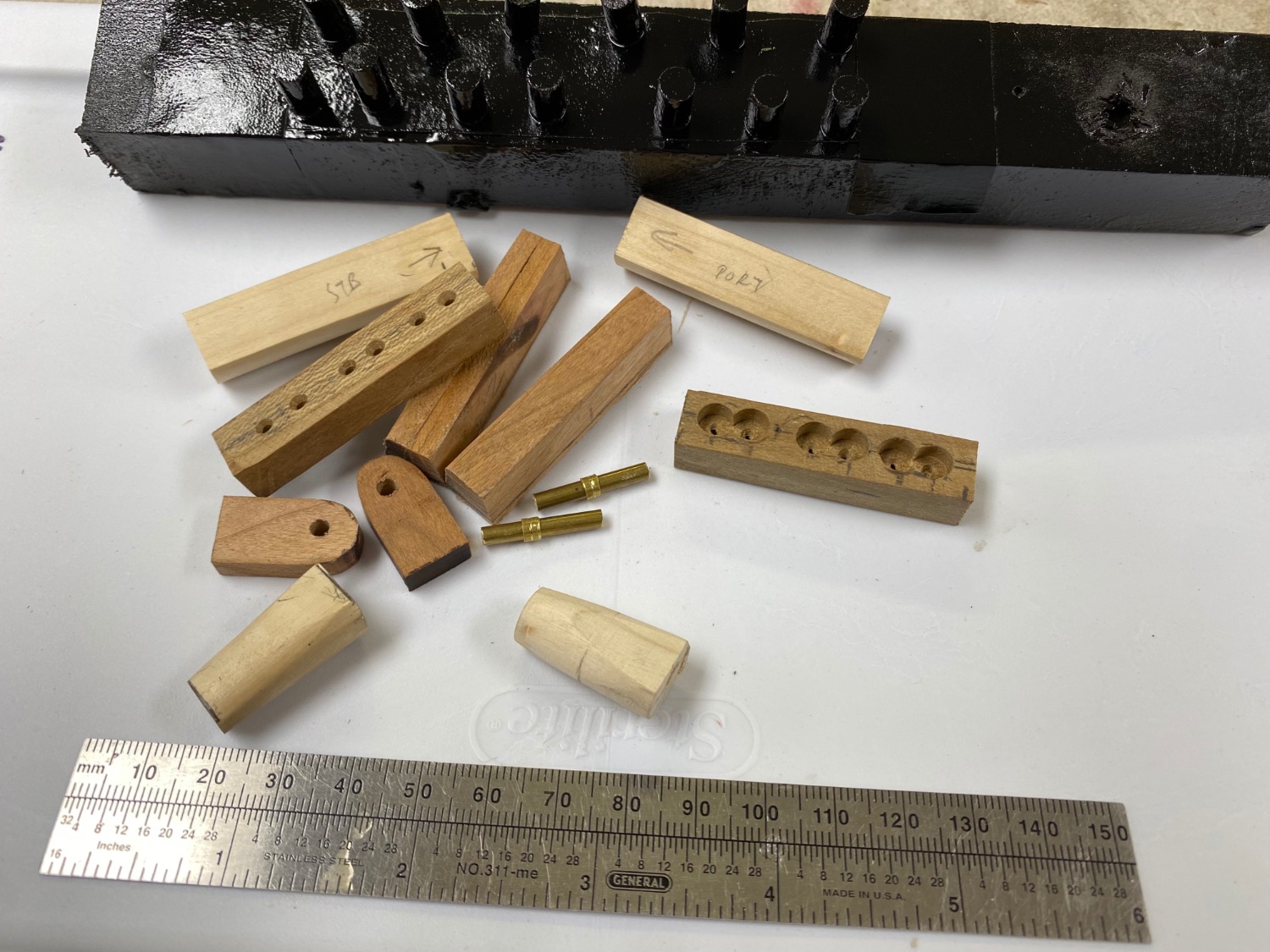
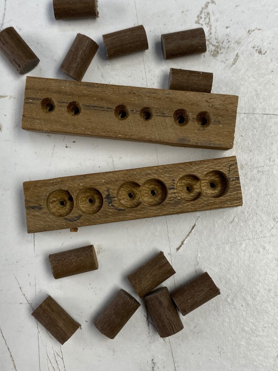
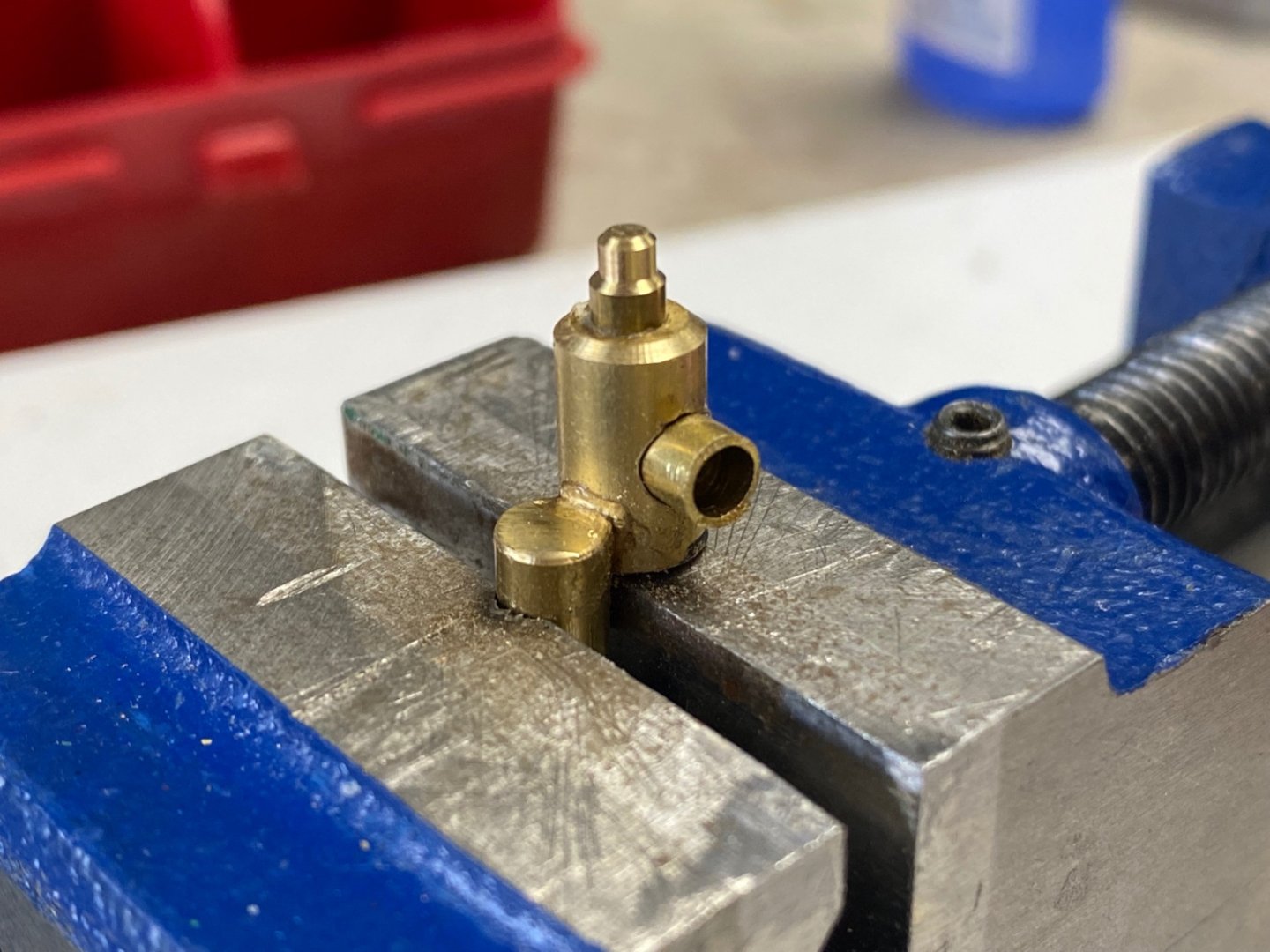
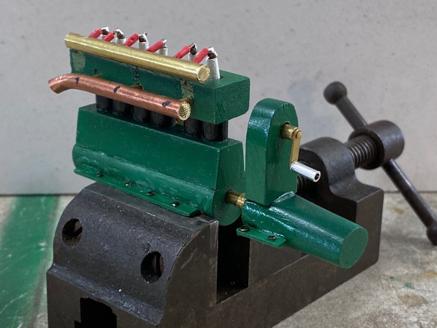
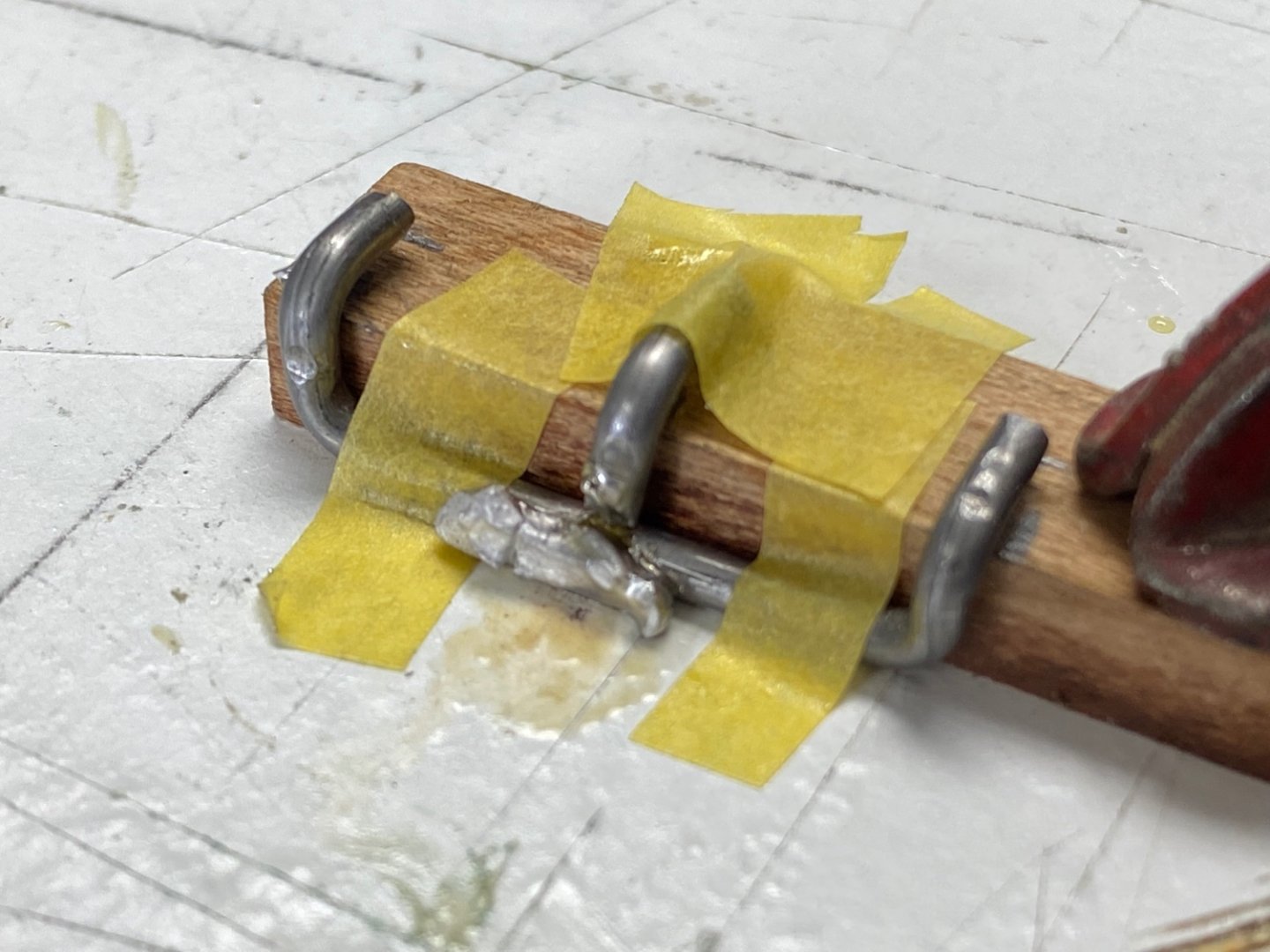
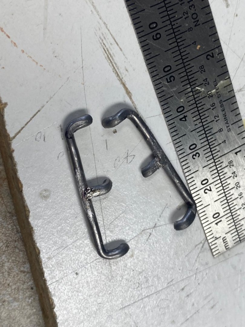
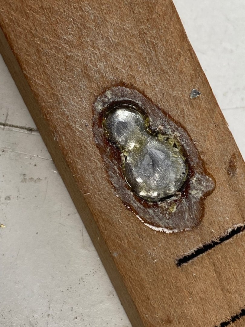
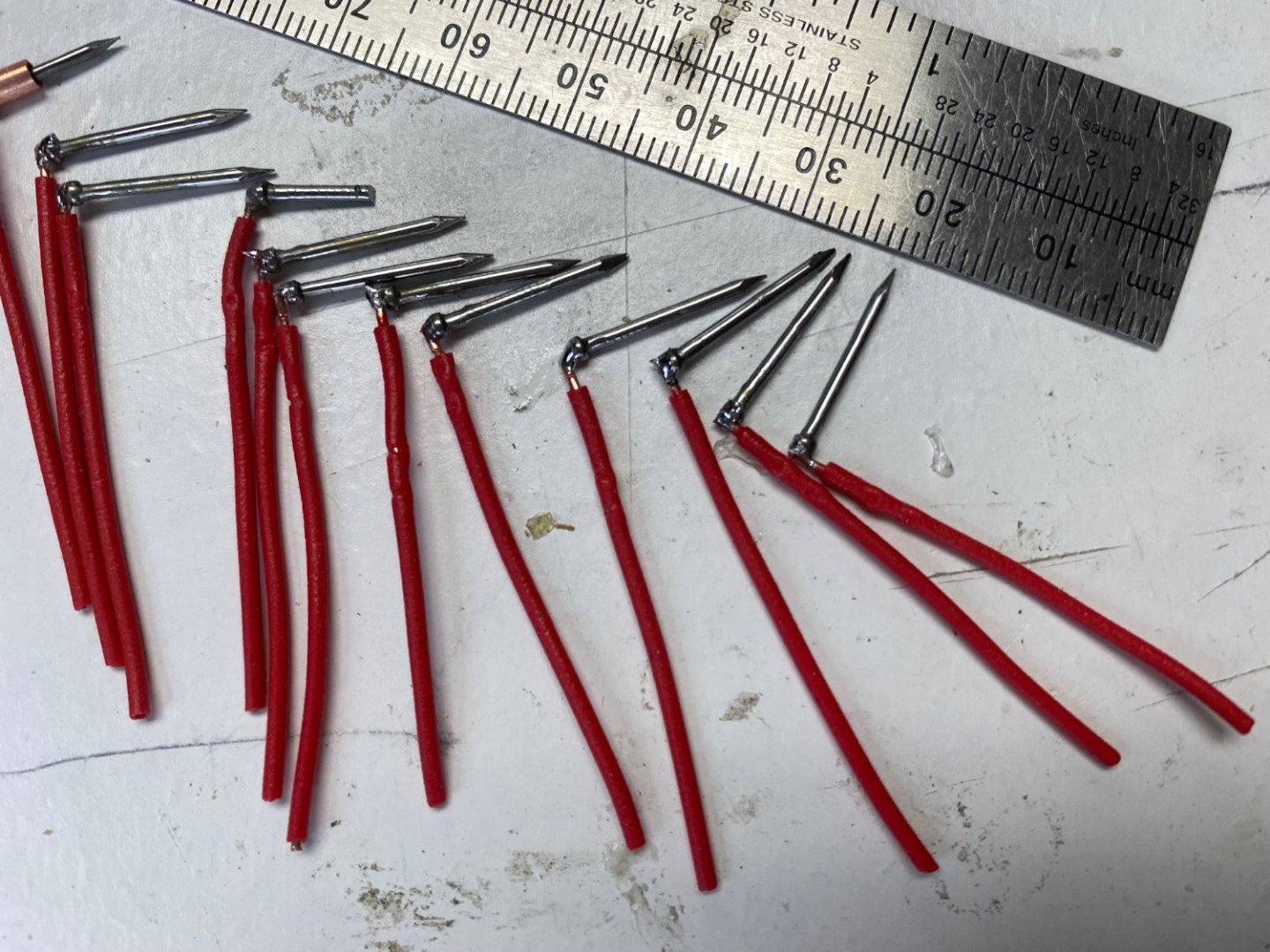
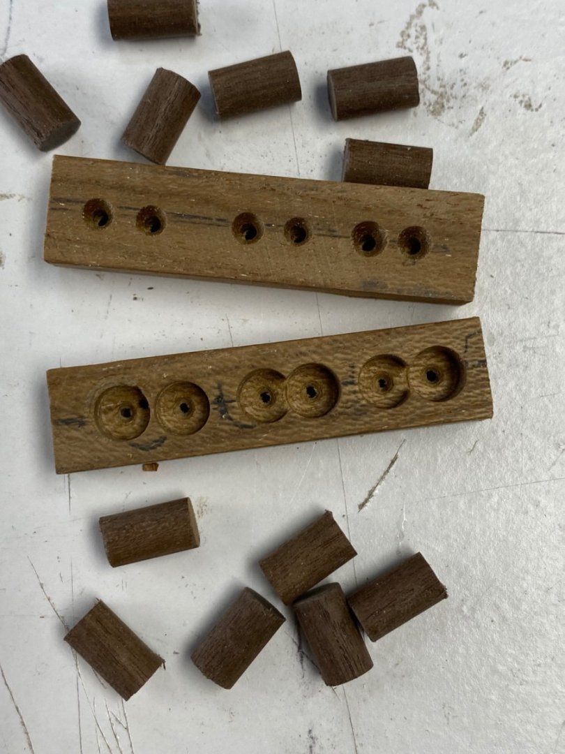
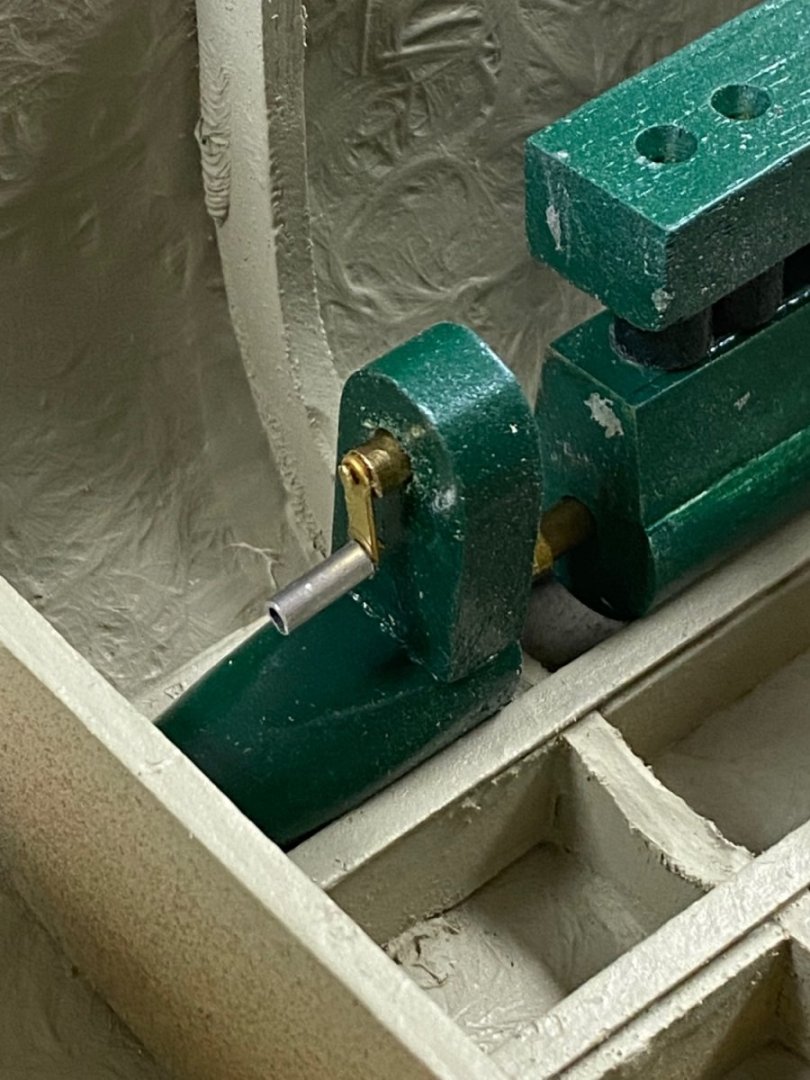
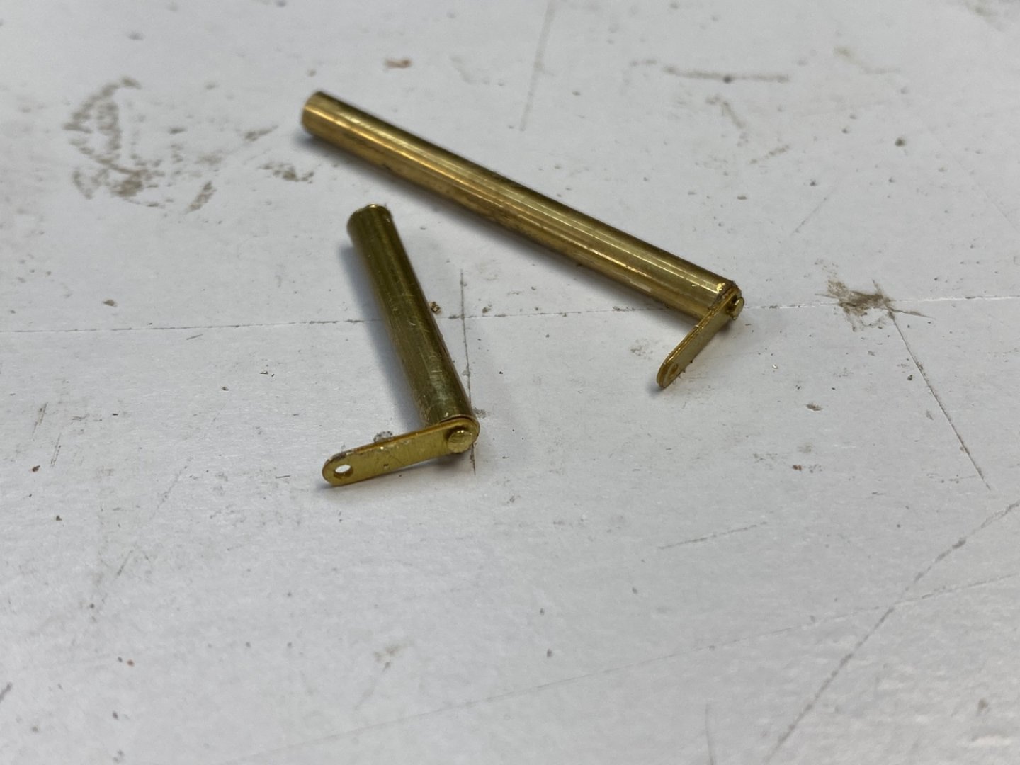
Continuing with the engines, I tackled the intake manifold using solder material that was the same diameter that I needed. I did some experiments with the soldering with some failures. Too much solder I refined my technique and using the same jig came out with two acceptable manifolds. The carburetors are coming up next and I had the great idea of casting them using the same low temperature solder. As a test, I made a mold drilling a piece of hardwood and proceeded to melt the solder into the holes. So far so good. Another catastrophe. I could not remove the lead from the mold. If I make the mold out of metal, what can be used as a mold release? I am now thinking making a simile of a SU carburetor using brass tubing and lathe turned brass rods. Any suggestions? Your comments will be appreciated I then turned to the other end of the engine and fabricated the spark plugs. The one on the far left shows the brass jacket that will be painted white to represent the porcelain and the nails will be clipped to fit the holes previously made in the cylinder head. I will them make a manifold where to introduce the cables and direct them to the far end of the engine where the magneto will be located. Thank you for your likes and comments.
-
Being working on a simile of the petrol engines. The following photo shows the various parts built. The crankcase, transmission and starting crank support. Cylinders, and cylinder head housings. The engine being assembled. The starter cranks. And finally the engine dry fitted to the boat. I also installed the fore and aft sub-decks with the marked accessories I am now researching the engine attachments such as carburetor, magneto, plugs, intake and exhaust manifolds. Most of these will not be visible once the cabin roof is in place but, I thought that the engine would not be complete without them. I am having a lot of fun researching and figuring out what to use to represent these items. Thanks to all you for the likes and comments.


-
Steve, you deck details are amazing at that scale in styrene. Will follow your progress.
-
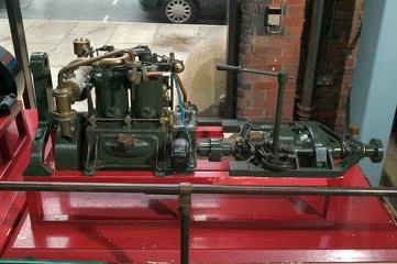
Wefalk, thanks for the effort and the information. I went to the Overton museum site and I found a tiny picture (thumbnail) of the type of engine arrangement similar of what I need. Since I am not building this model for a museum or for historical accuracy I am going to go with a "representation" of what I think the engines would have looked like.The thumbnail I found follows . Very similar with the arrangement I have seen. Thanks again.
-
Looking forward to your jolly boat. I had a hard time making mine for Amapá at almost twice you scale.
-
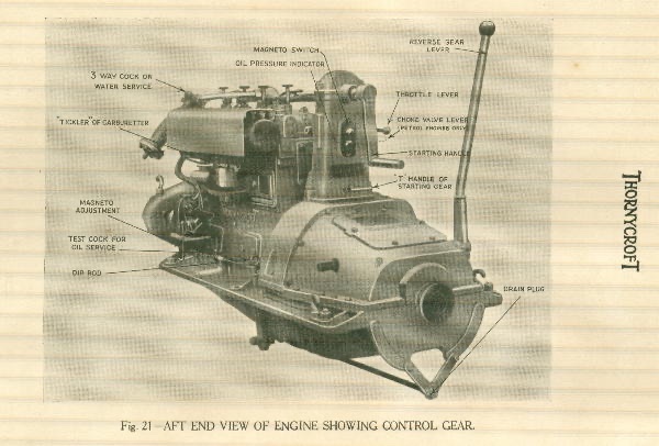
Wefalck, I miss your comments and your amazing knowledge of the history of these ships. I am working on Amapá internal structure and found differences between the molded hull that I bought and the plans of the actual boat. Right now I am fabricating the two petrol engines. Unfortunately, I have found very little information on the actual engines installed in the boat. In my searches on google the closet thing I found is the following So I am now working to replicate it (somewhere within my tolerance). Most of the Thornycroft information I found is for diesel engines and essentially later engines. If you have any better data let me know. I am trying to figure out the actual controls from the helm.
-
Keith, I am now working on another WWI boat: the HMS Mimi that fought the Germans in Lake Tanganyika after a 3000 miles trek from Cape Town to the lake. I started a build log on it.
-
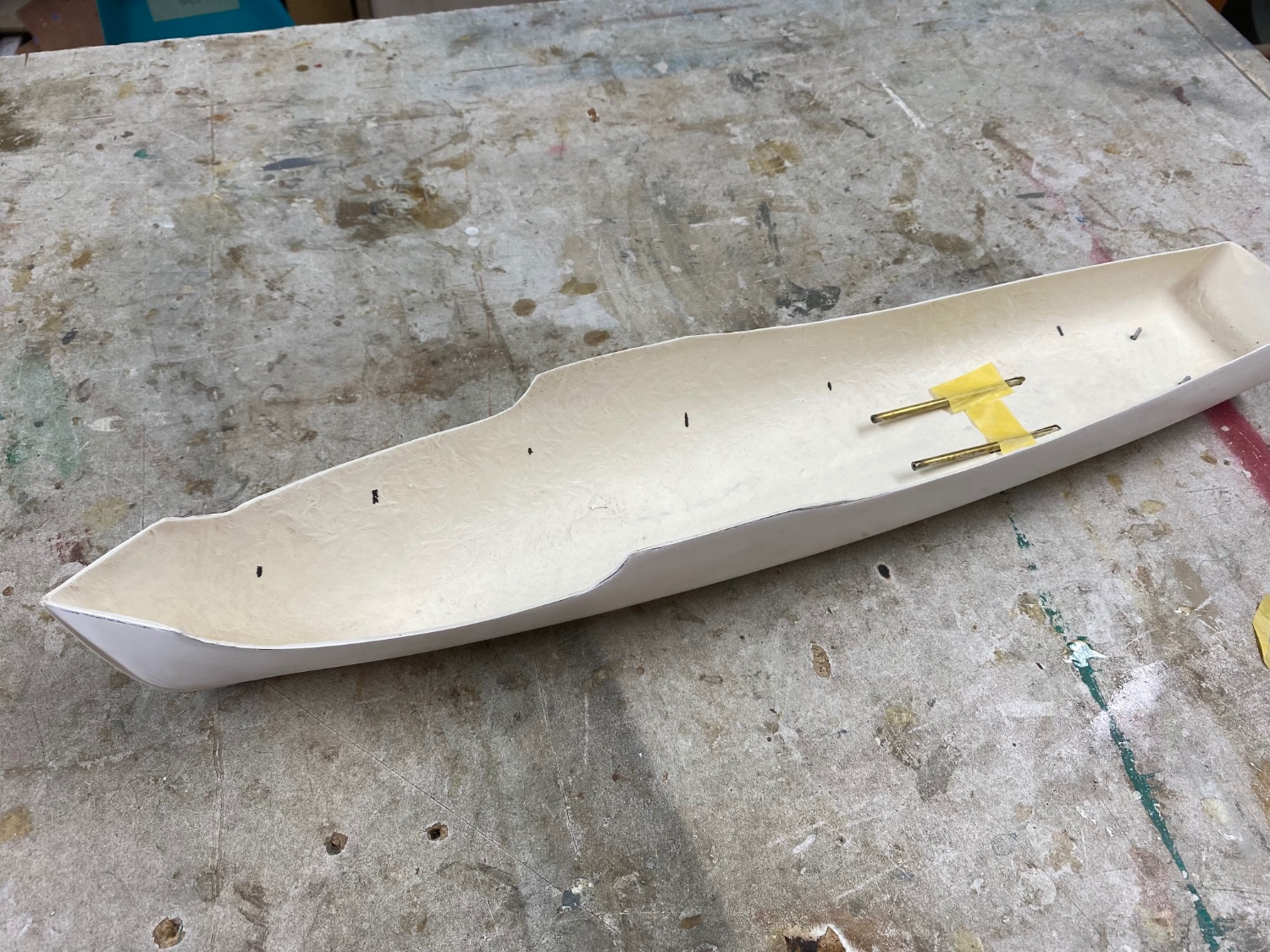
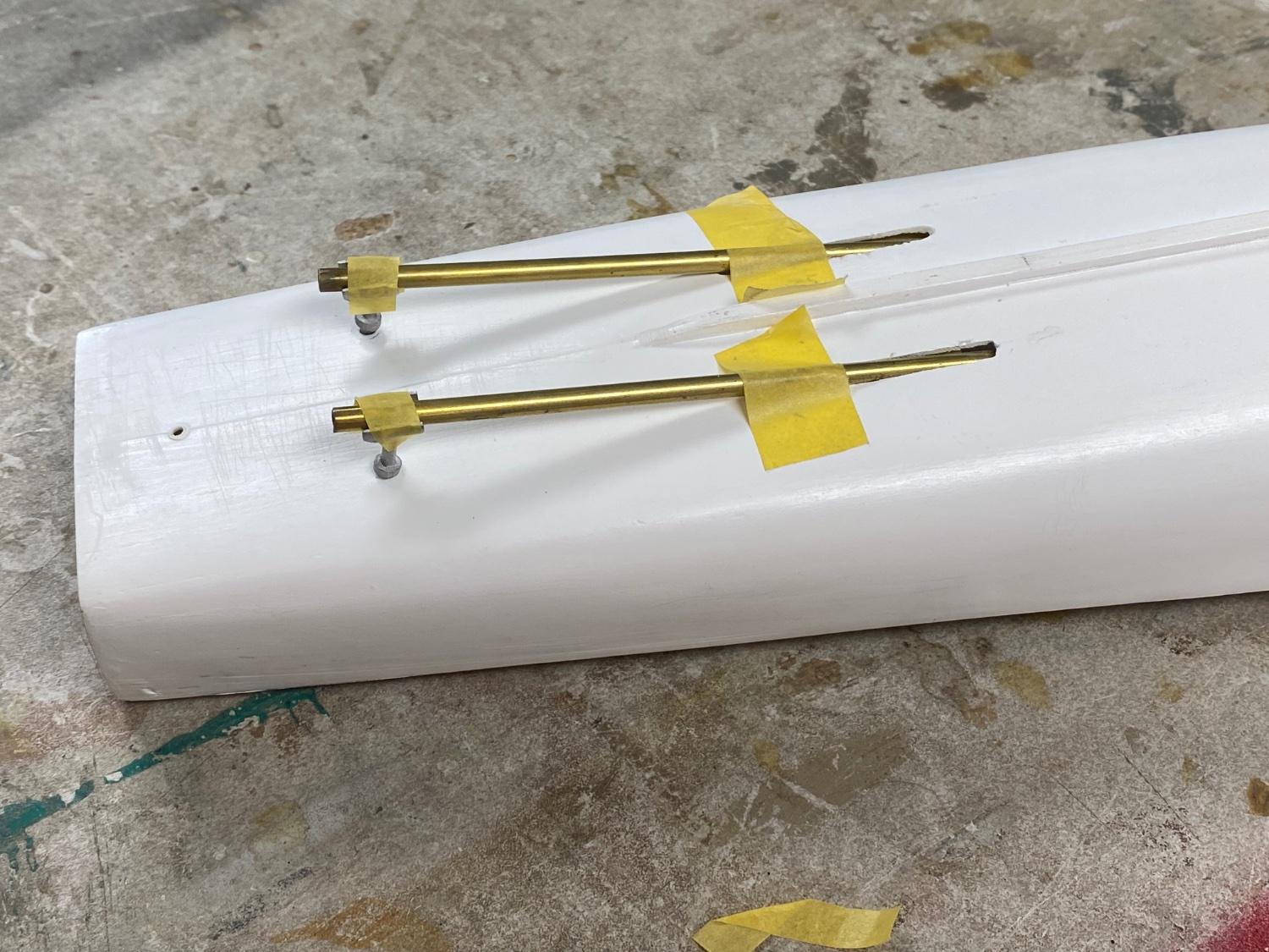
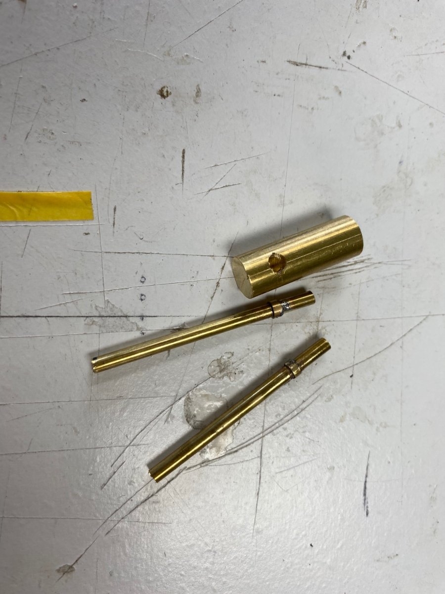
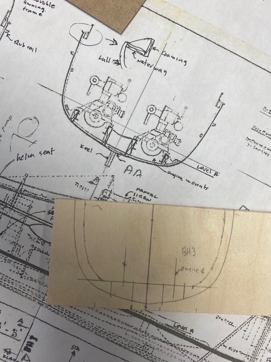
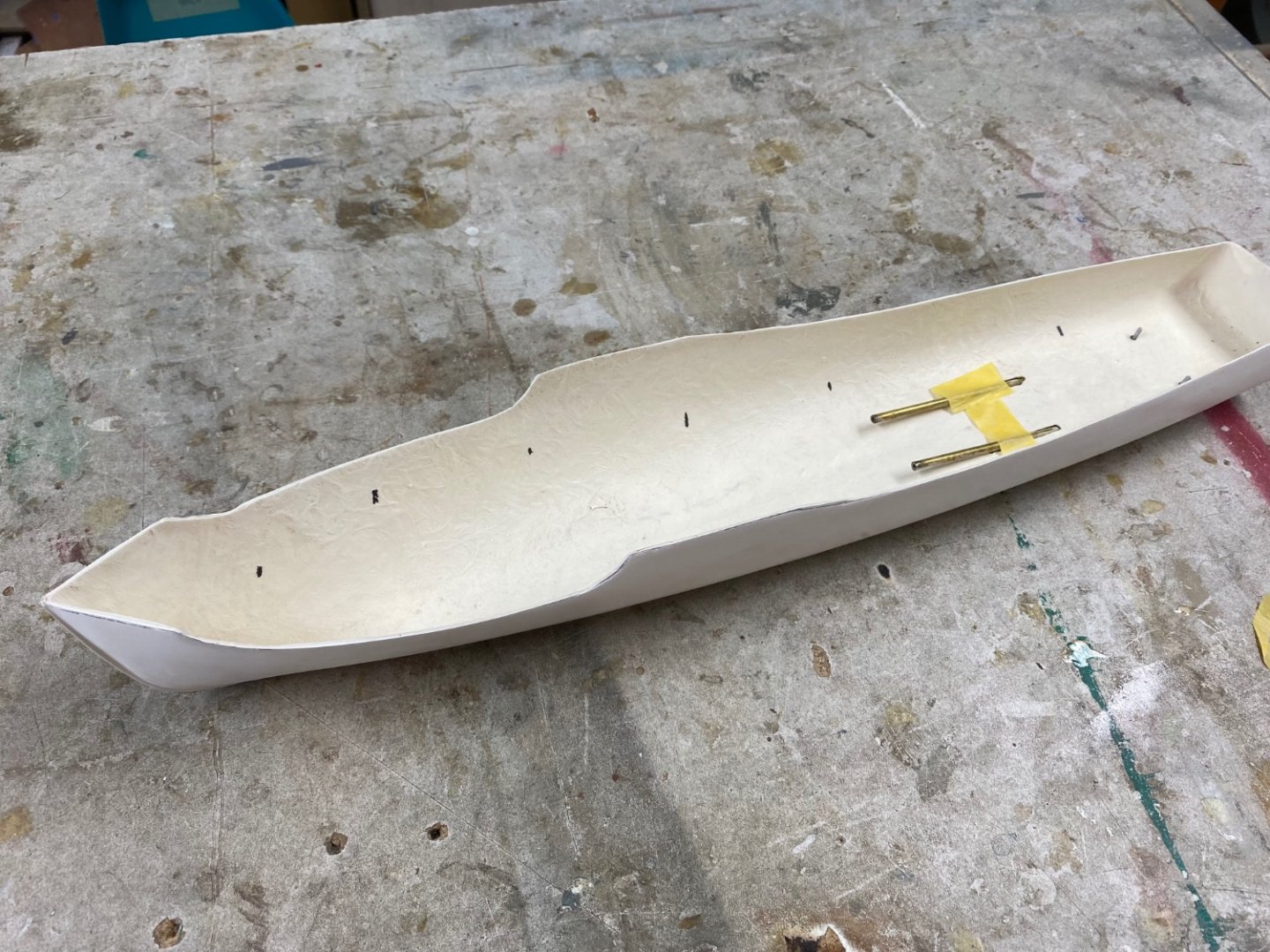
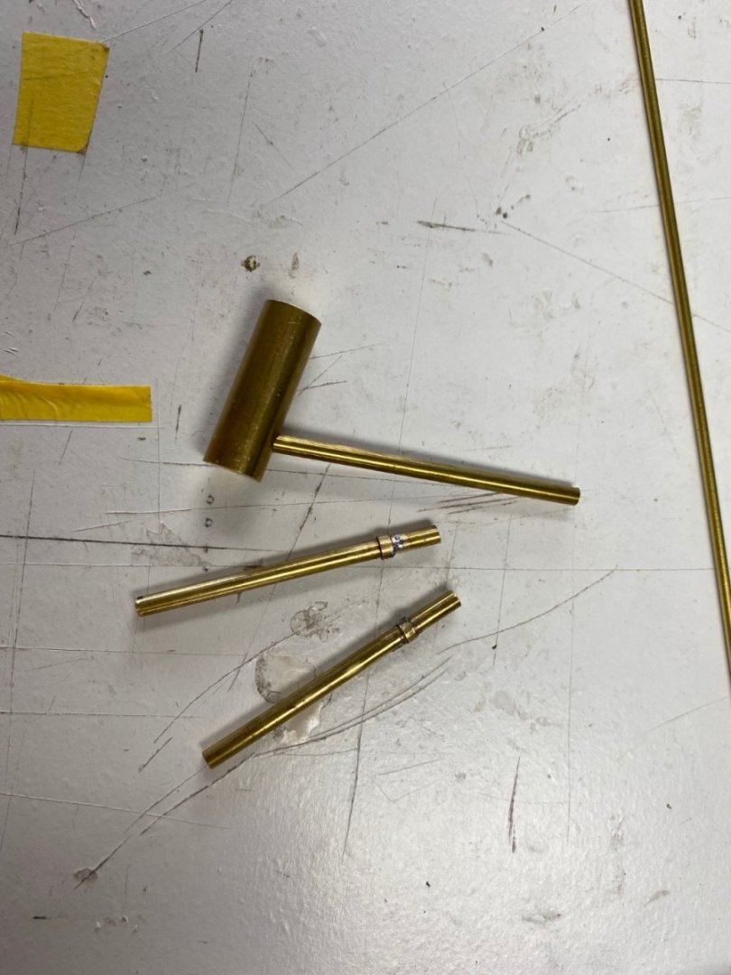
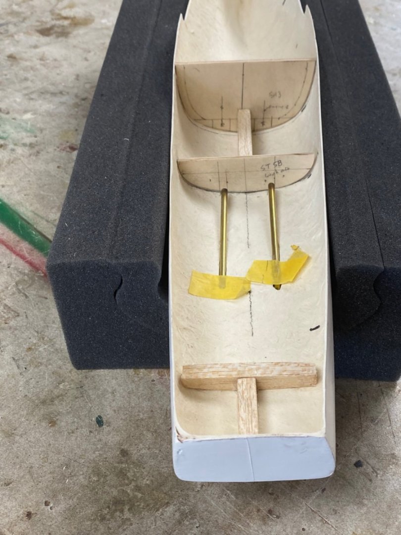
The cradle is finished and I started the fabrication of the propellers support brackets. These were furnished in the kit, but they are kind of rough so I am going to reproduce them in brass. But then I realized I had to set the shafts first to see the layout and get the right angle on the supporting shafts. Following is the dry fit of the shafts using the white metal fittings Started the fabrication of the supports after measuring the actual angle of the shafts and these are the parts. Then, I set up my Unimat lathe to reduce the part of the exposed shaft and tragedy ensued. After I finished the first shaft my 3 jaw chuck locked up and I couldn't get the piece out of the chuck. I decided to proceed with the build by fabricating the hull frames that will fill the empty hull. For these I used the only plan that I have available (see my post #1). Then I found that the Dean's hull actually does not totally match the original plans of this vessel so I have been making templates until I got the right layout. I also reinforced the thin hull where the propeller supports and the rudder will be installed. Then, one of my neighbors helped me with the unlocking my 3 jaw chuck and I will be back in business tomorrow. 👍


-
Thanks guys, I really appreciate your comments and, as I have said before, I couldn't have done it without you support and information. I have been building models since I was 8 years old, now I am 86 years old and still learning skills in this magnificent hobby. Now I am embarking in another challenge building HMS Mimi and I hope you keep me in line. Thanks
-
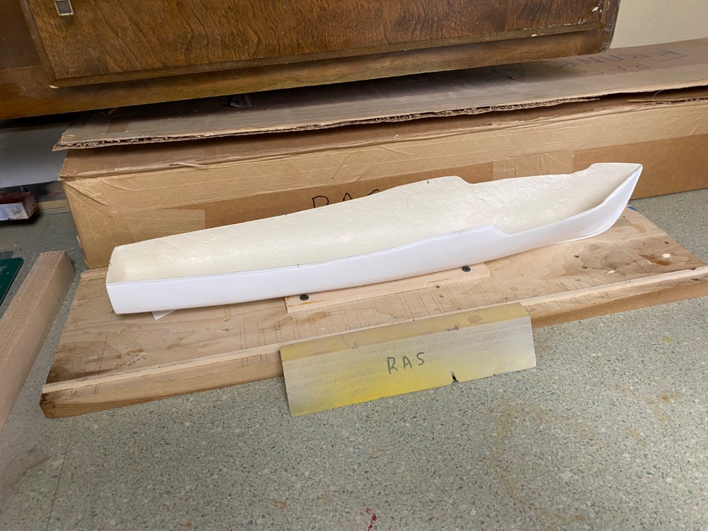
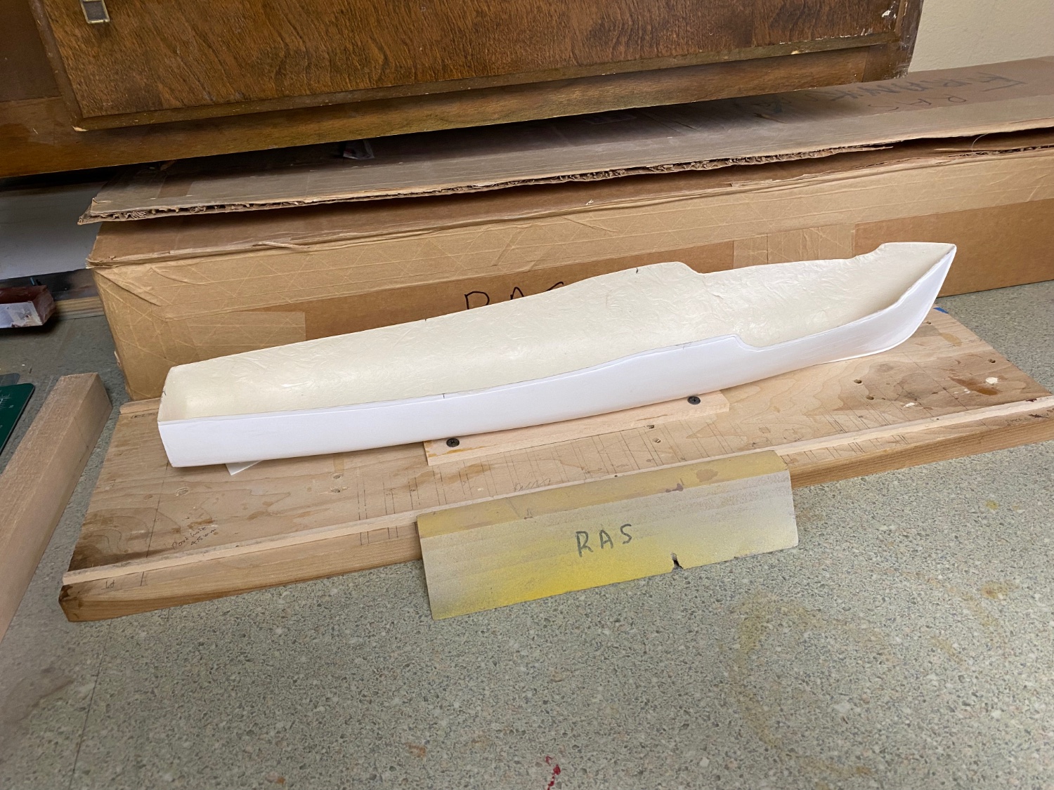
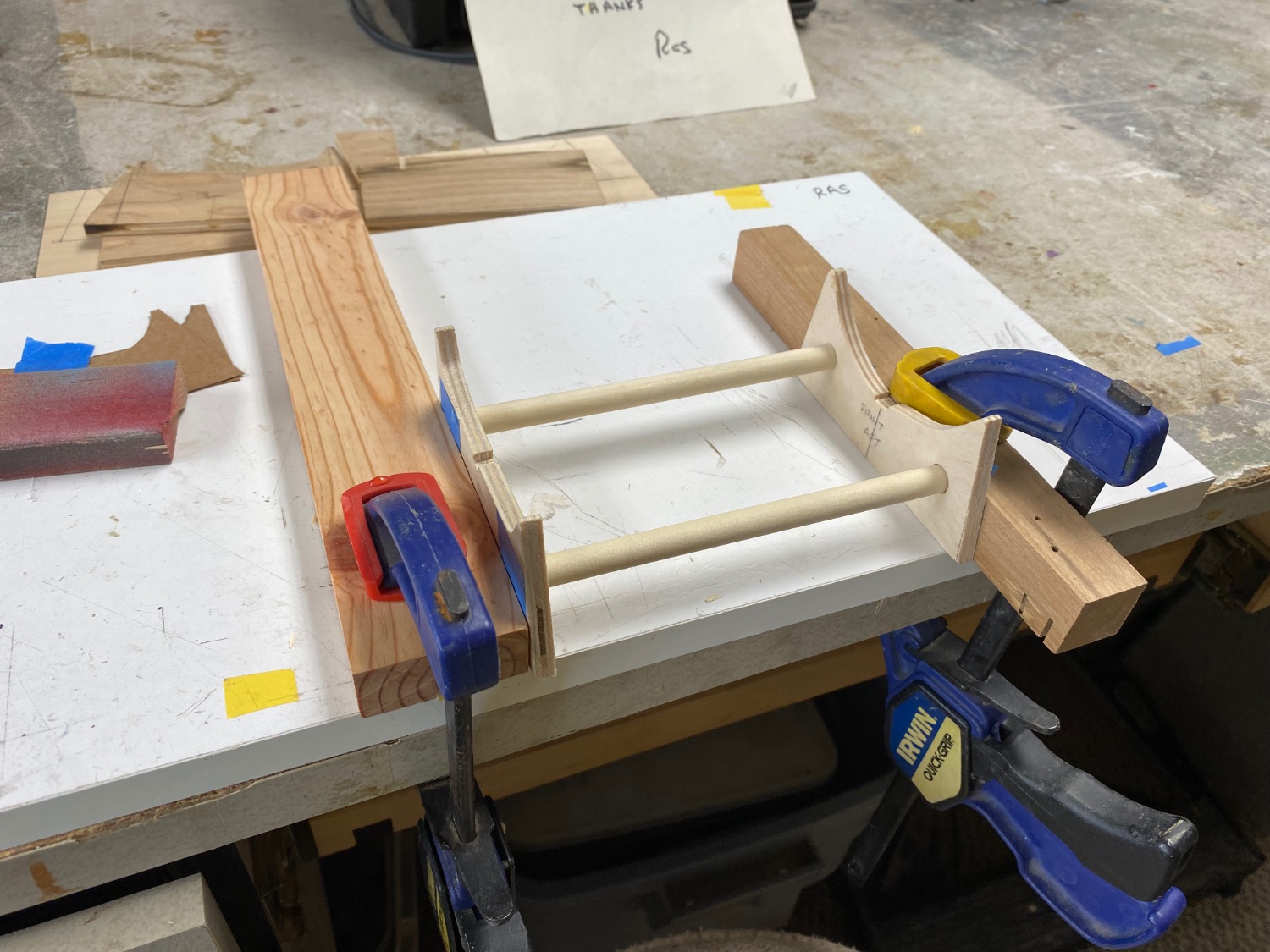
Well guys, Amapá is finished and now is resting on display at the lobby my building. So, it is time to start building Mimi. The first thing was to clean the hull to remove the mold waxes. Then I started fabricating the hull cradle. This is Mimi in her building board: And this is the cradle drying the glue. More to follow soon.