modeller_masa
-
Posts
950 -
Joined
-
Last visited
Content Type
Profiles
Forums
Gallery
Events
Everything posted by modeller_masa
-
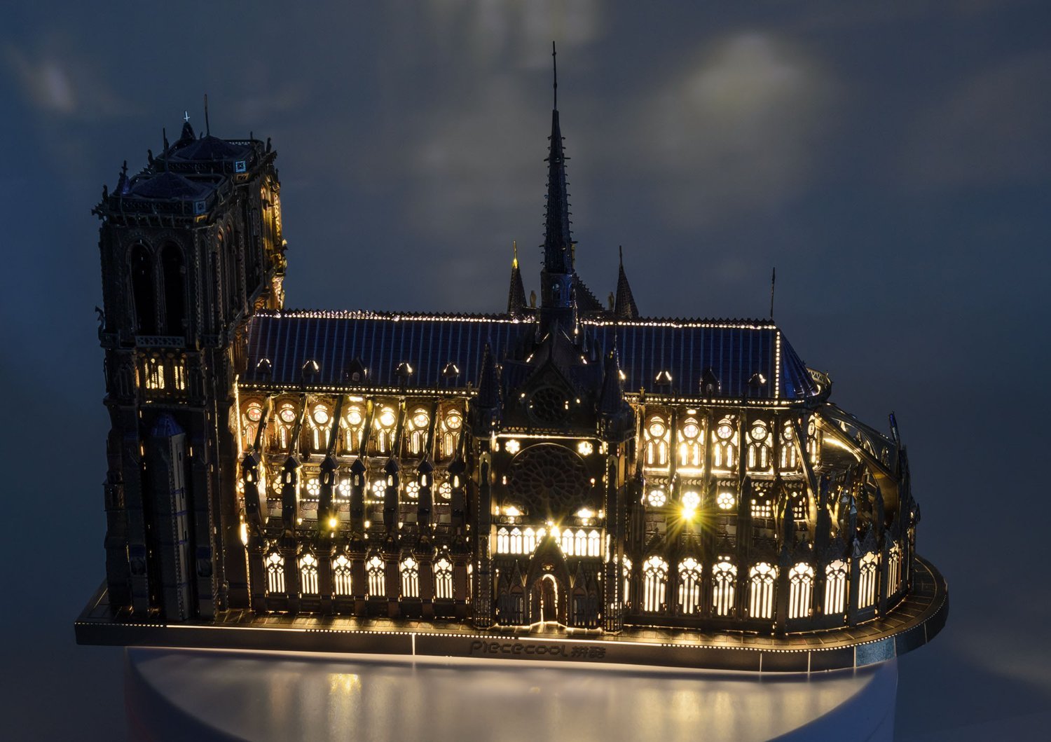
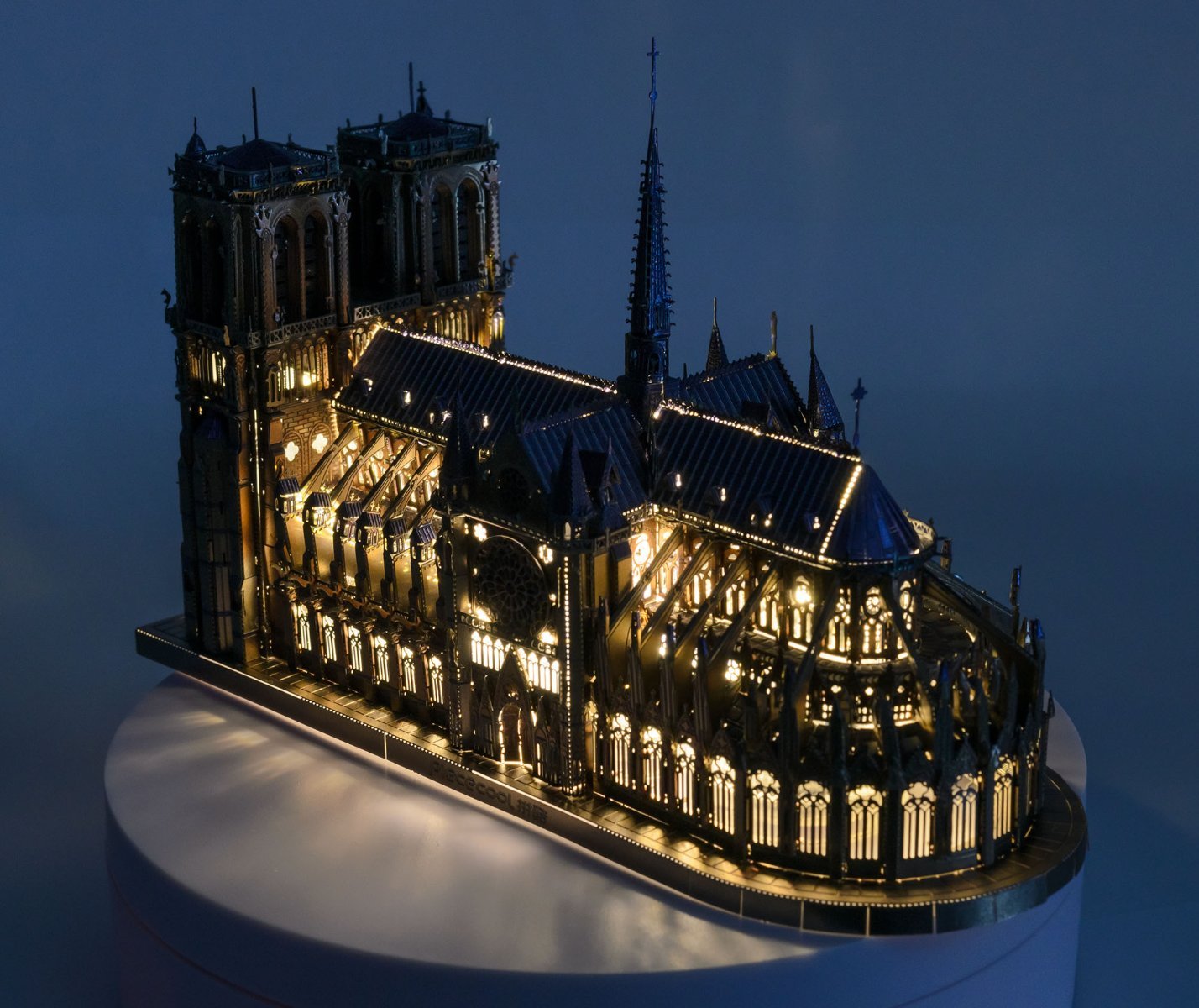
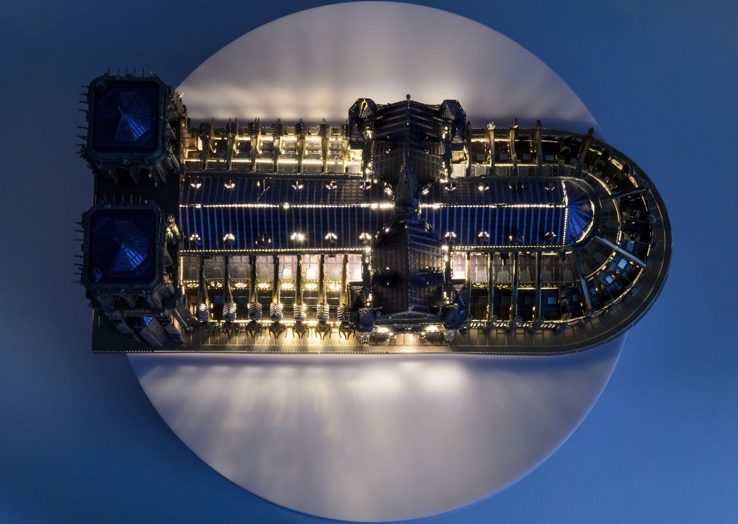
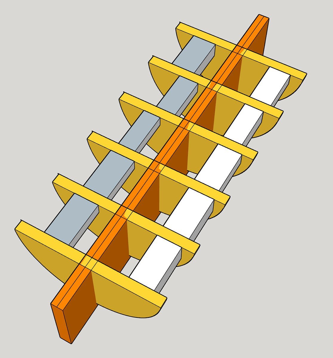
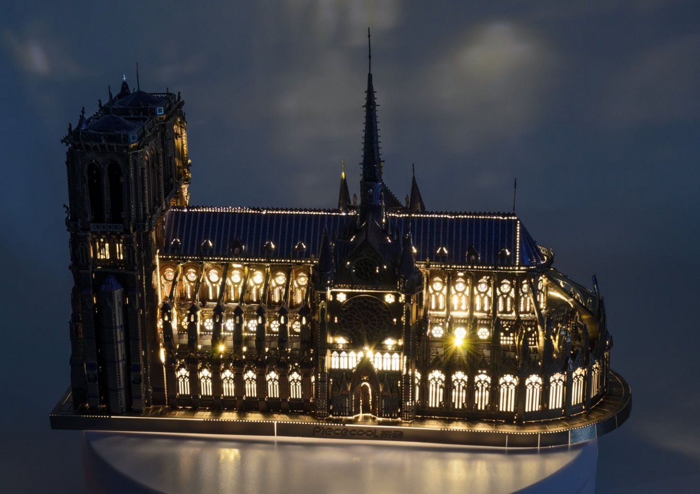
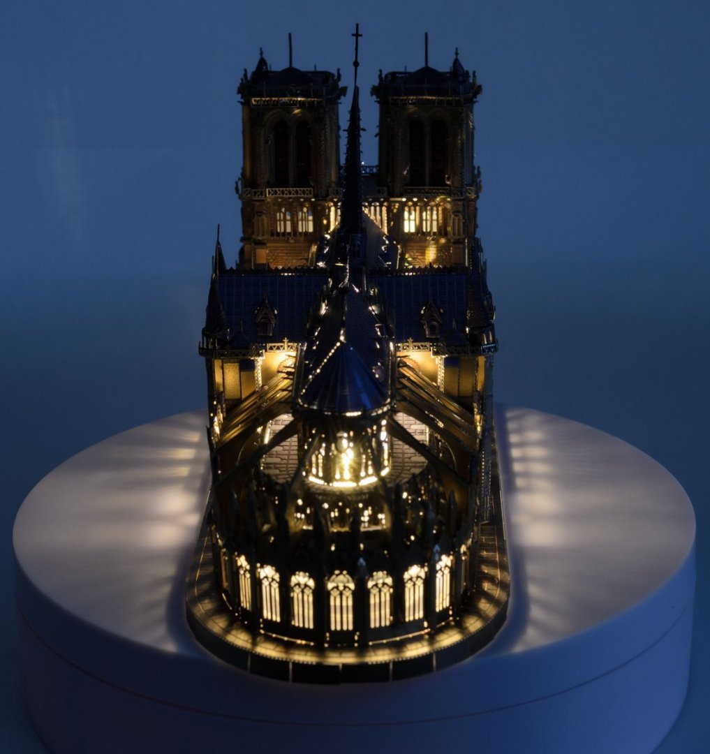
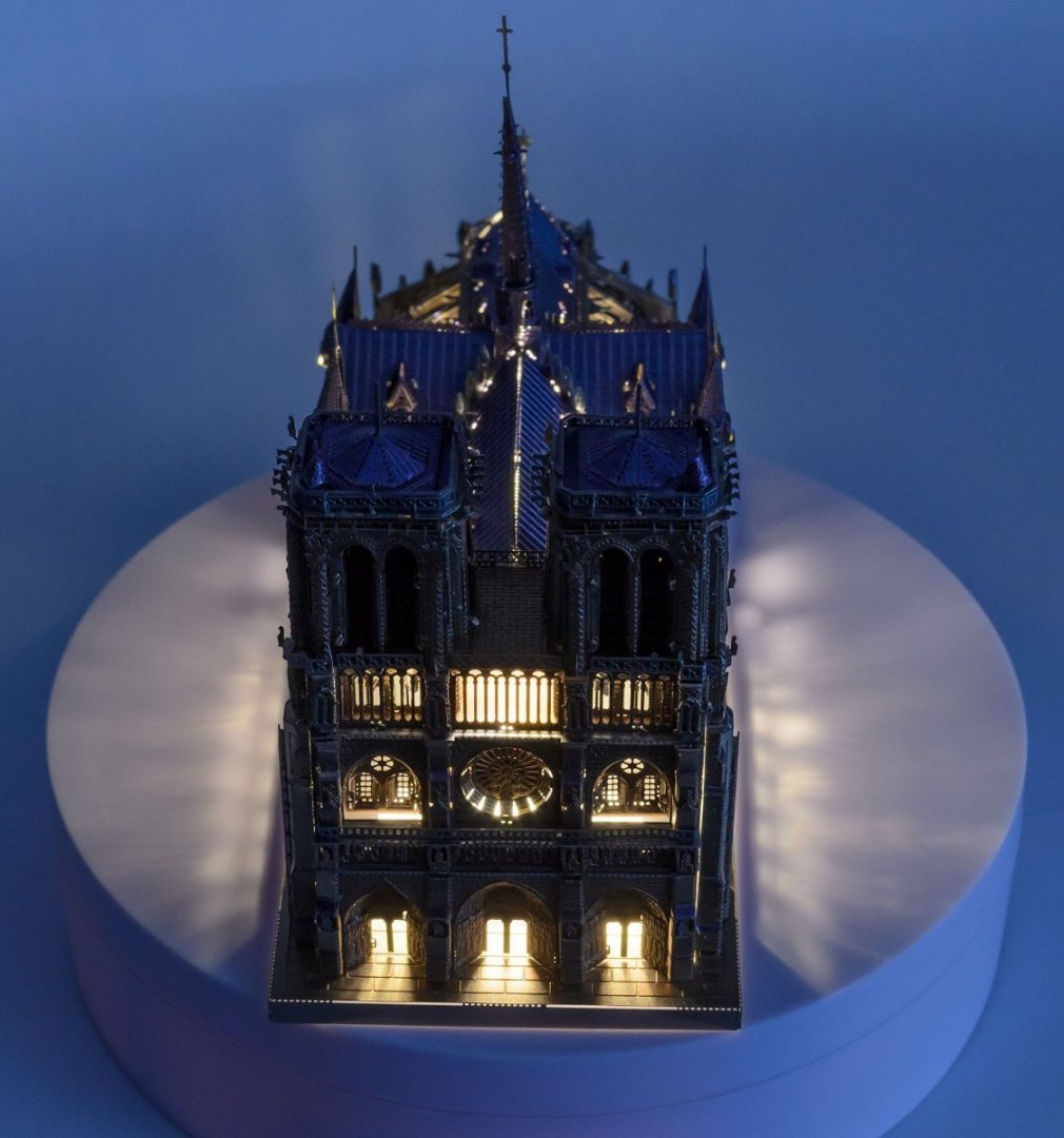
Hello, While I was working on the first planking, I made a Metal-earth like model from Piececool. I spent approx. 20 hours completing this kit. It is a non-scale kit, and I think approx. 1/850. Thanks for watching it. https://modelshipworld.com/topic/28420-hms-beagle-by-techtonic-finished-occre-160/#comment-813144 By the way, I found an interesting method to recycle used runners from the kit. I would say that the edges of the metal piece are dangerous, but it is a genius idea.


-
- 13
-

-

-
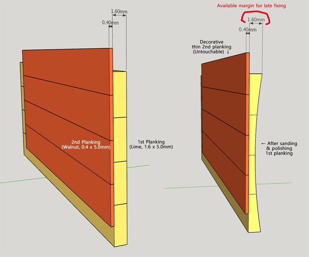
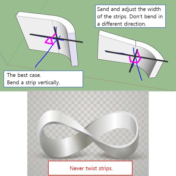
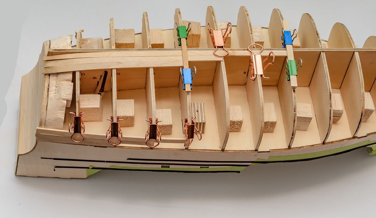
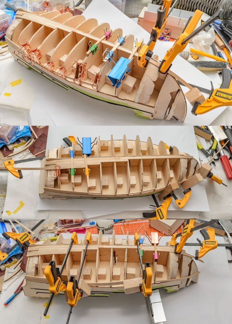
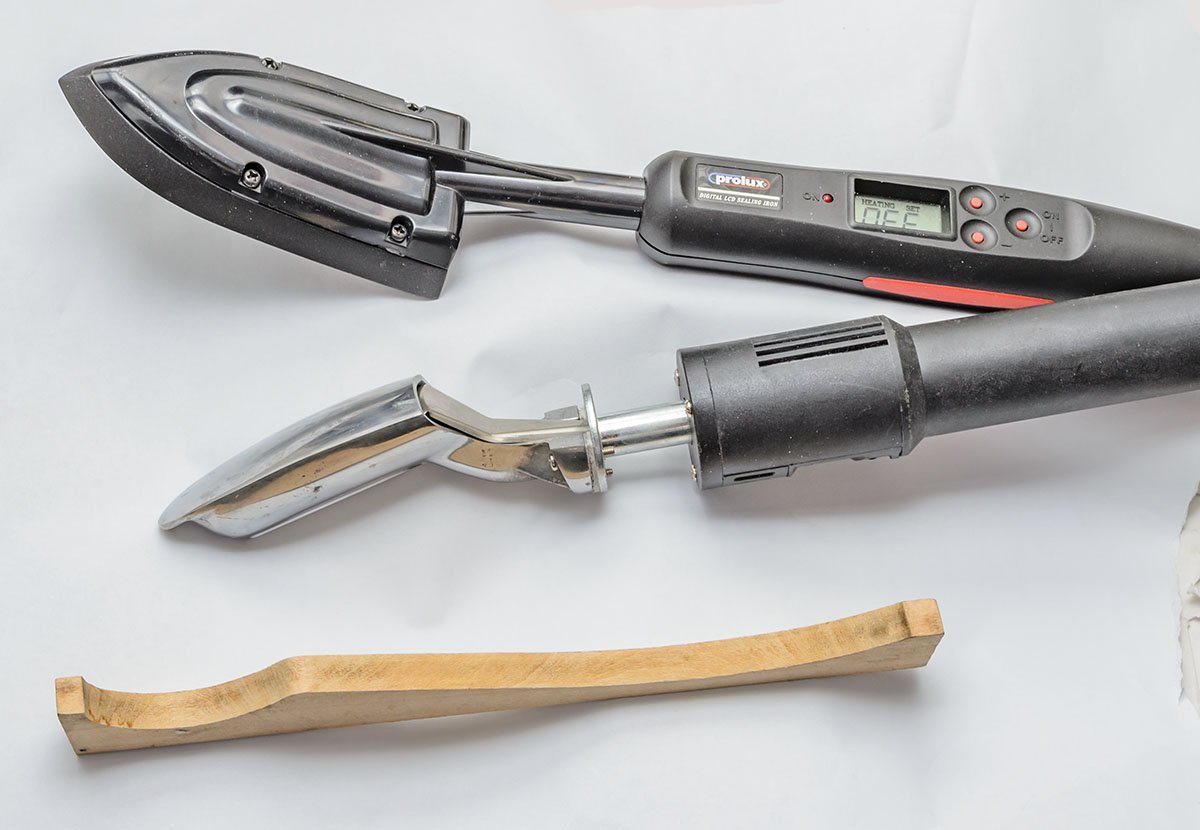
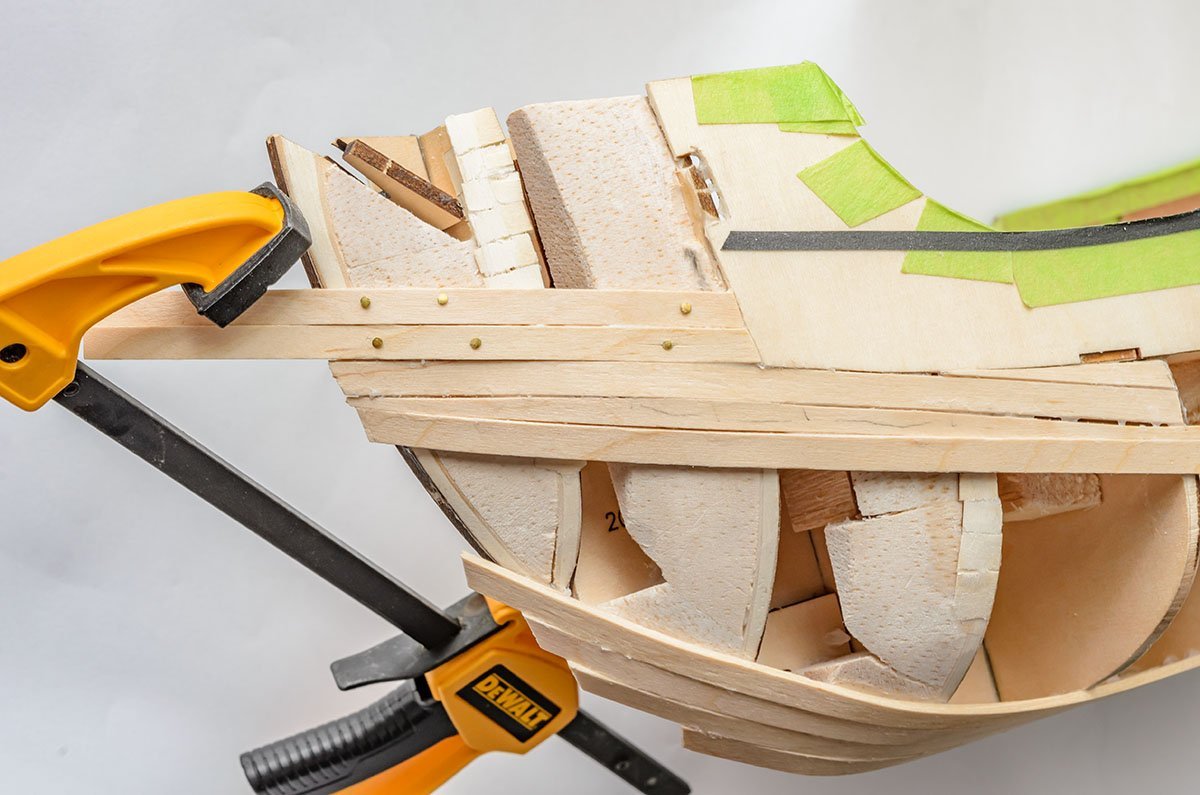
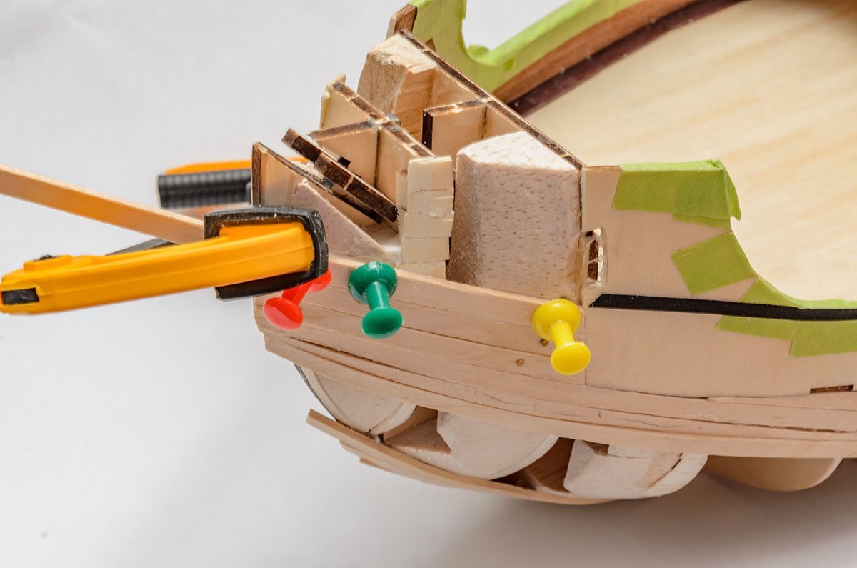
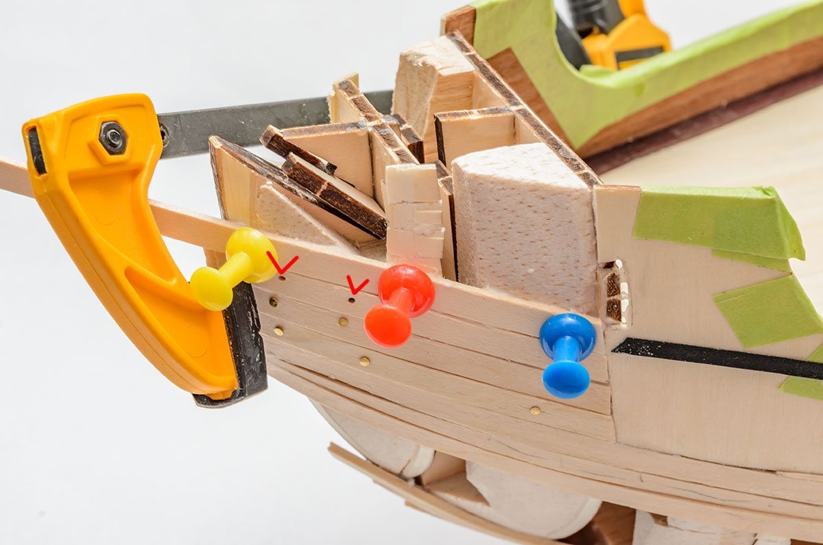
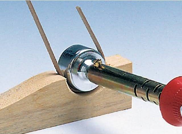
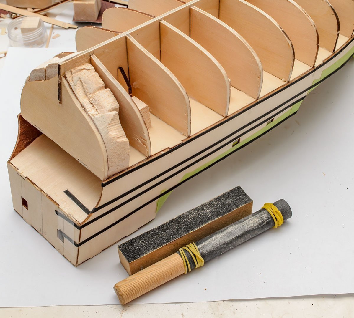
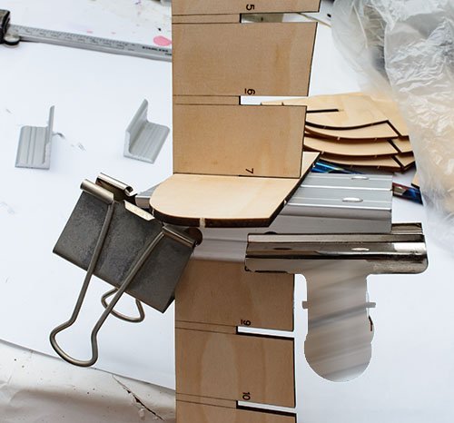
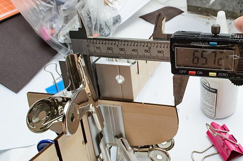
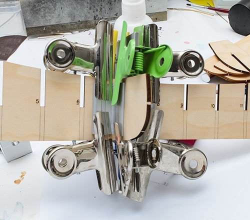
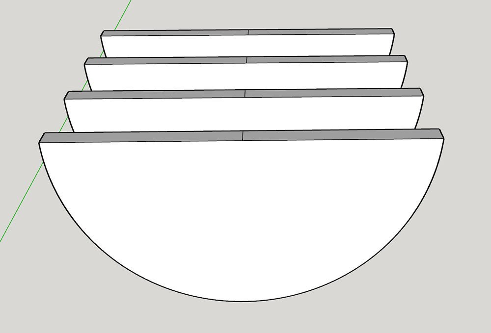
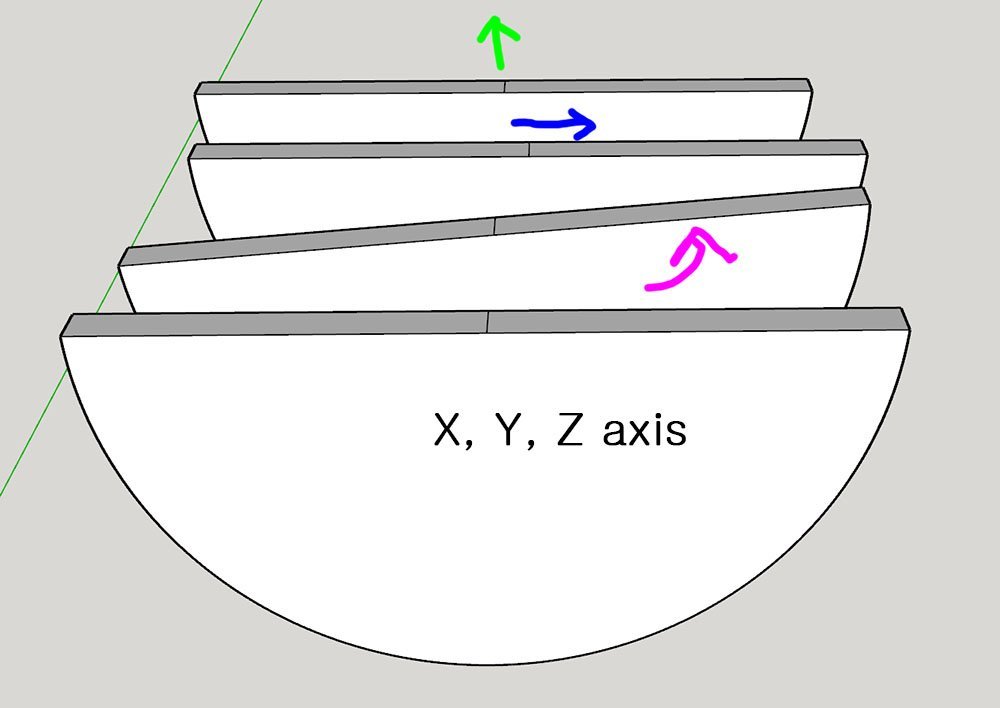
I started the first planking. Before I explain the methods of the planking, I would like to summarize the purpose of the first planking in the case of the 2nd planking kit. When the kit includes the second planking, we don't need to make the first planking beautiful. The second planking will cover the entire surface of the first planking. We should focus on how to sand and polish the surface of the first planking, which will be a bed for the second planking. By the way, the diagram is a bit wrong. I sanded the inside of the first planking. I already decided an entire hull shape when I finished the hull fairing. If the strips are floating like this, it means I'm wrong because I'm changing the finished hull fairing. Make sure the first planking strips stick to the frames tightly. I should have removed the strip and tried again. Yet another rule. Don't try to force strips too much. If you use lots of clamps to hold a strip, it means something is wrong and the hull shape will be twisted. Simply push the strips vertically and wrap the hull. If you find a gap between strips, sand and make a thinner strip to fill the gap. It is the first planking, so we don't need to pay attention to removing gaps too much. There should be thousands of ways to hold planks. There are many useful buildlogs that introduce various planking techniques. Not all of them are efficient and fast, but we aren't racing. Try everything and find the most comfortable and useful planking technique for you. Nailing brass nails is probably the most famous technique. I also had high expectations for hammering nails when I began a wooden model ship, and was disappointed soon after because the brass nailing is just different shapes of clamps rather than decorations. 😆 These are the benefits and disadvantages of nailing, in my opinion. Benefits + The small installation space allows I to continue planking work. + With a proper hammering tool, it is quite fast and easy. + Almost every planking strips can be clamped, especially in place where woodworking clamps are difficult to use, such as the bow and stern. Disadvantages - It requires supporting wood under the planking strips. (Balsa wood blocks may solve this issue.) - Some woods, such as very weak or too narrow, aren't good at this. Nails may cause a crack. (Drilling holes before hammering may solve this issue.) - The brass nails are a bit expensive unless you buy them in a bulk on eBay. You may want to retrive the nails after the PVA bond is done, but it is quite difficult and dangerous. - When we remove the nails, there are about 0.70mm holes. (It can be covered by wooden fillers.) If you are making the first planking only model ship, you should find another way. - Sanding strips with the nails is a bit awkward, like scratching a blackboard with fingernails. 😬 - The remaining brass nail will cause some trouble. It turns black and beomes a bit swollen after a month. I'm making the second planking ship, so it won't be a huge issue. However, if you make the first planking ship with paint on the hull, the remaining brass will leave lots of unwanted dark spots on your hull through white paint. Using a push pin is the better option, in my opinion. It is easier to remove, and the wider cross-guard clamps strips more tightly. I can use a washer to expand the cross-guard. The holes are 1.10mm which is wider than brass nails. As I wrote, it can be filled by wooden filler. Before you use the nails or push pins, make sure you add balsa wood blocks to the frames. (You don't need to sand the balsa wood block for hull fairing.) Some kits, including this AL Santa Maria kit, have a too narrow 2.80mm frame that isn't sufficient to make a nail hole. In my personal opinion, the best method to install planking strips is to do the ironing. Water and heat mold a curved strip like a plastic model kit's parts. I really don't need any clamps to attach the pre-molded strips. 😆 The wooden piece at the bottom is a part retrieved from the AL's iron tool kit. The AL's iron is an analog type, so it burns wooden strips. I use a digital temperature controlled iron for leather craft. (Middle and top) I usually set the irons at 140 celsius degrees and less than 150 celsius degrees to prevent yellowing. The two irons have different head surfaces. I prefer the curved head iron. When I make a molded strip, I wet the strip well. I place the strip on the curved bed, and press it with a hot iron. The strip will generate some steam. When the steam is gone and the strip is dry, I get a curved strip within 30 seconds. Fast, safe, and the best quality. 😎 Read build logs as much as possible. There are many techniques I haven't seen yet. 👍
-
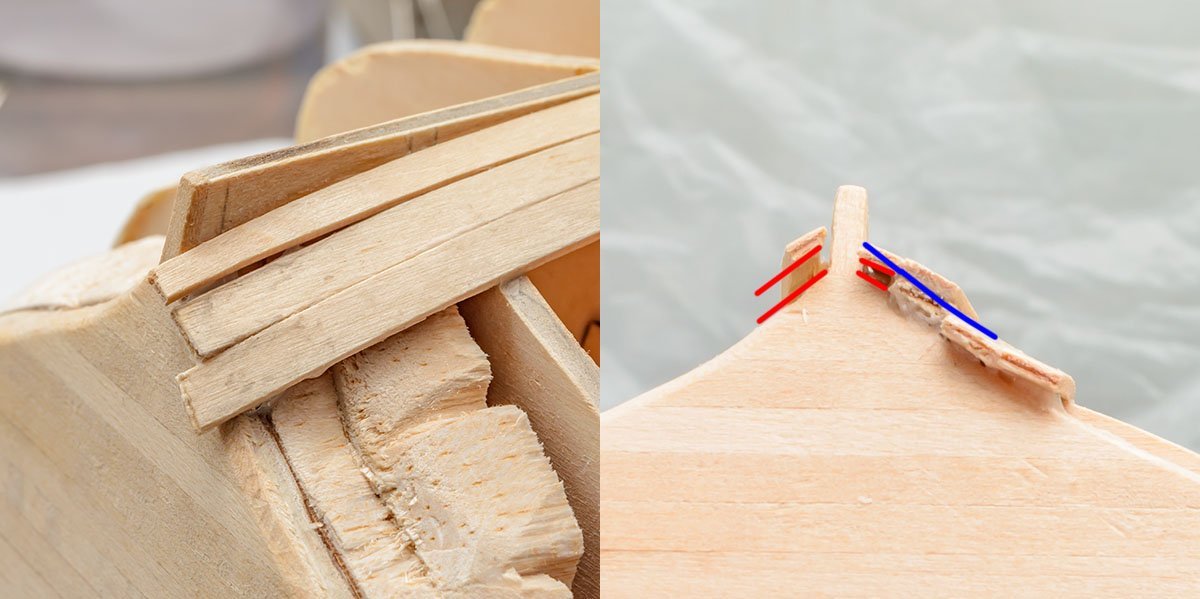
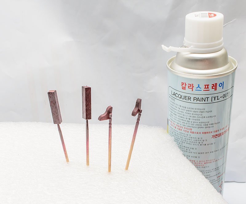
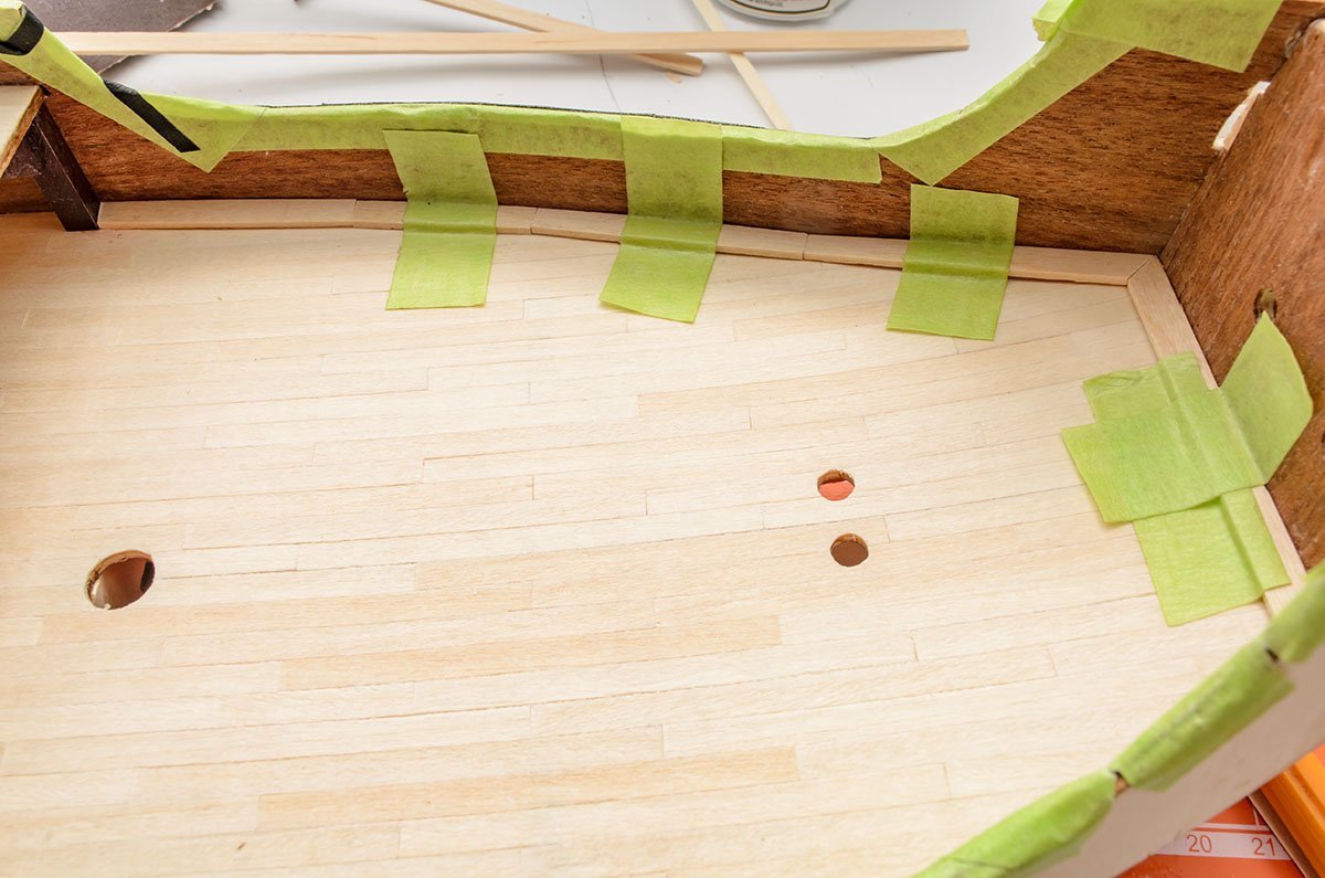
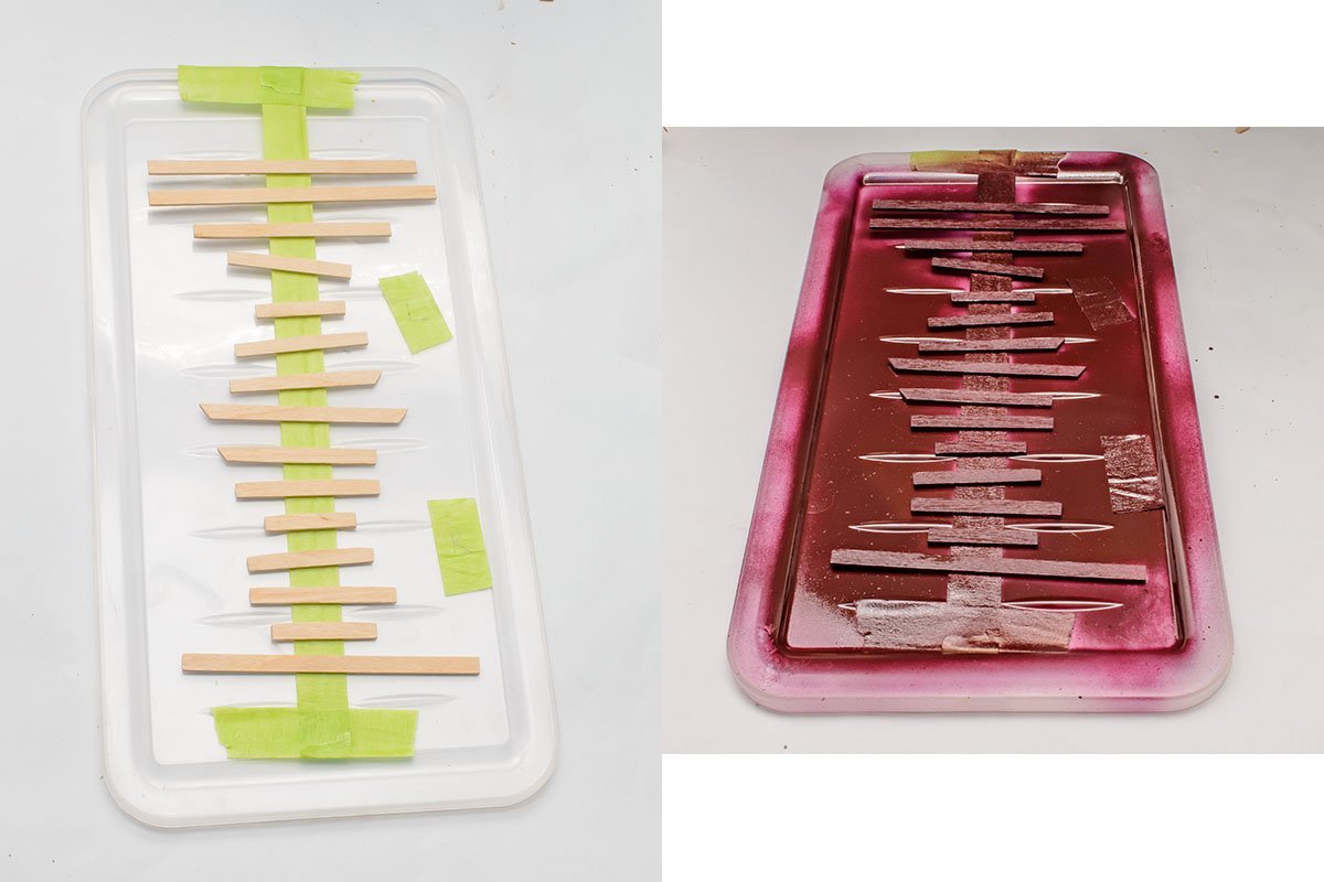
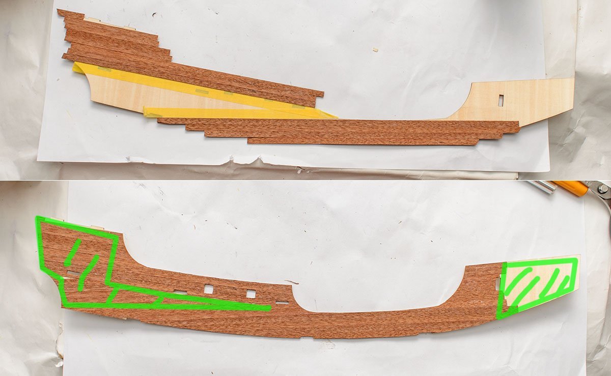
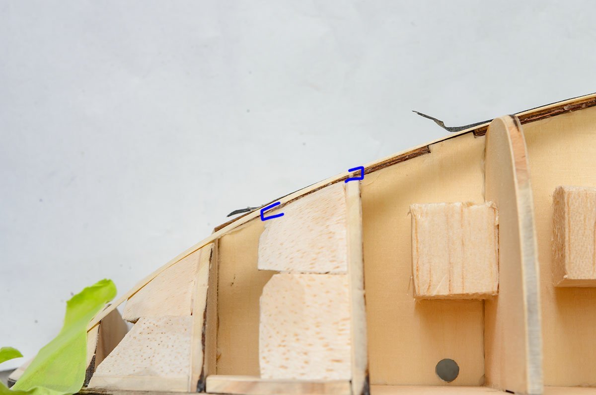
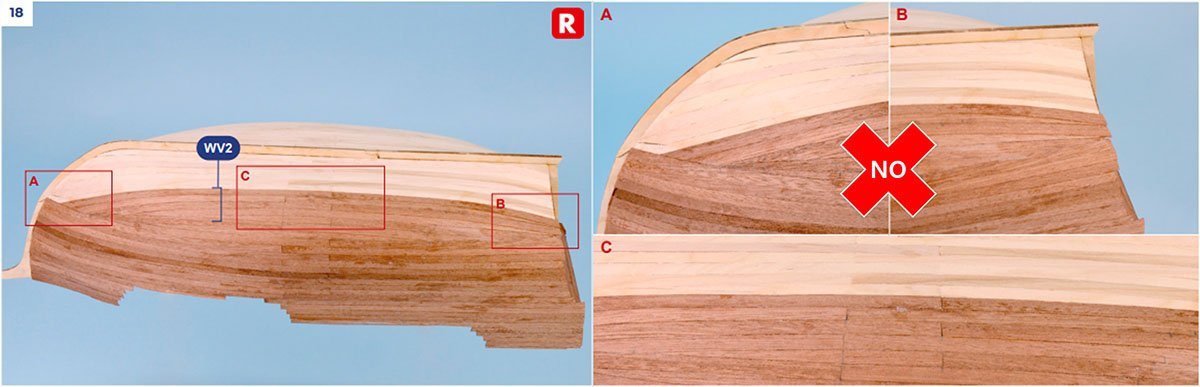
I added some decorations before staring the first planking. It will be difficult to touch the place after that. I painted the pillars with an industrial lacquer spray. The lacquer spray is a cheap and durable paint. I paid about $1.5 for 420ml. Just make sure to use it on the outside or under a good ventilation system. The manual says nothing about installing molds at the corners. I had to cut and sand strips to fit in the corners. I painted them again with lacquer paint. The color is maroon, and I used masking tape to hold the strips. OK, go to the planking! By the way, the manual doesn't say to install the moldings under the second floor. I used some strips, so they might not be enough for the other places. I finished the backside before hull planking. It is late night, so I'll sand them tomorrow. Without proper polishing on the strips, I'll see large gaps between the planks after sanding. (Red planks) It will also happen again when I do the first planking in a curved area. To avoid the issue, I sanded at the edge of each planks. (Blue planks) It isn't easy for new builders. It is hard to sand such a long area evenly. I recommend buying special tools such as a thumb plane. Othersize, use filler to fill the gaps. It's too late to run a sanding machine. See you next time. 😴
- 77 replies
-
- 3
-
-
- Santa Maria
- Artesania Latina
- (and 1 more)
-
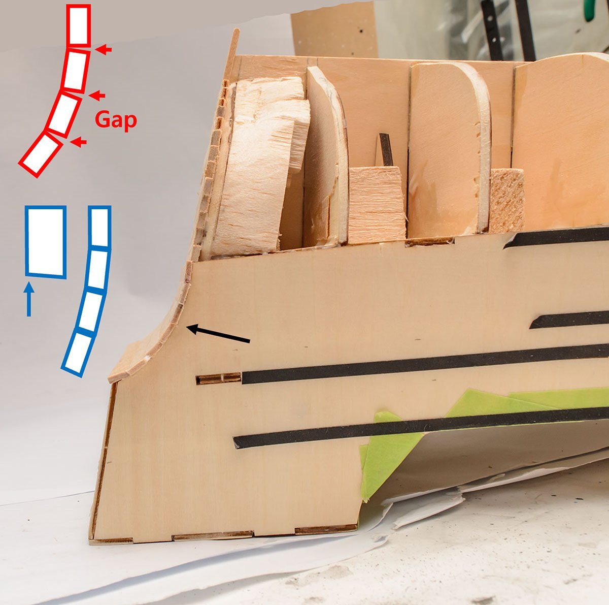
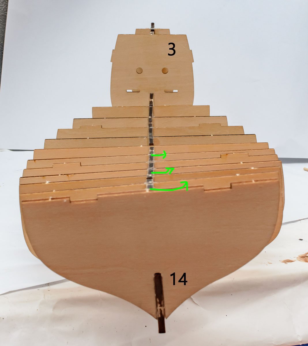
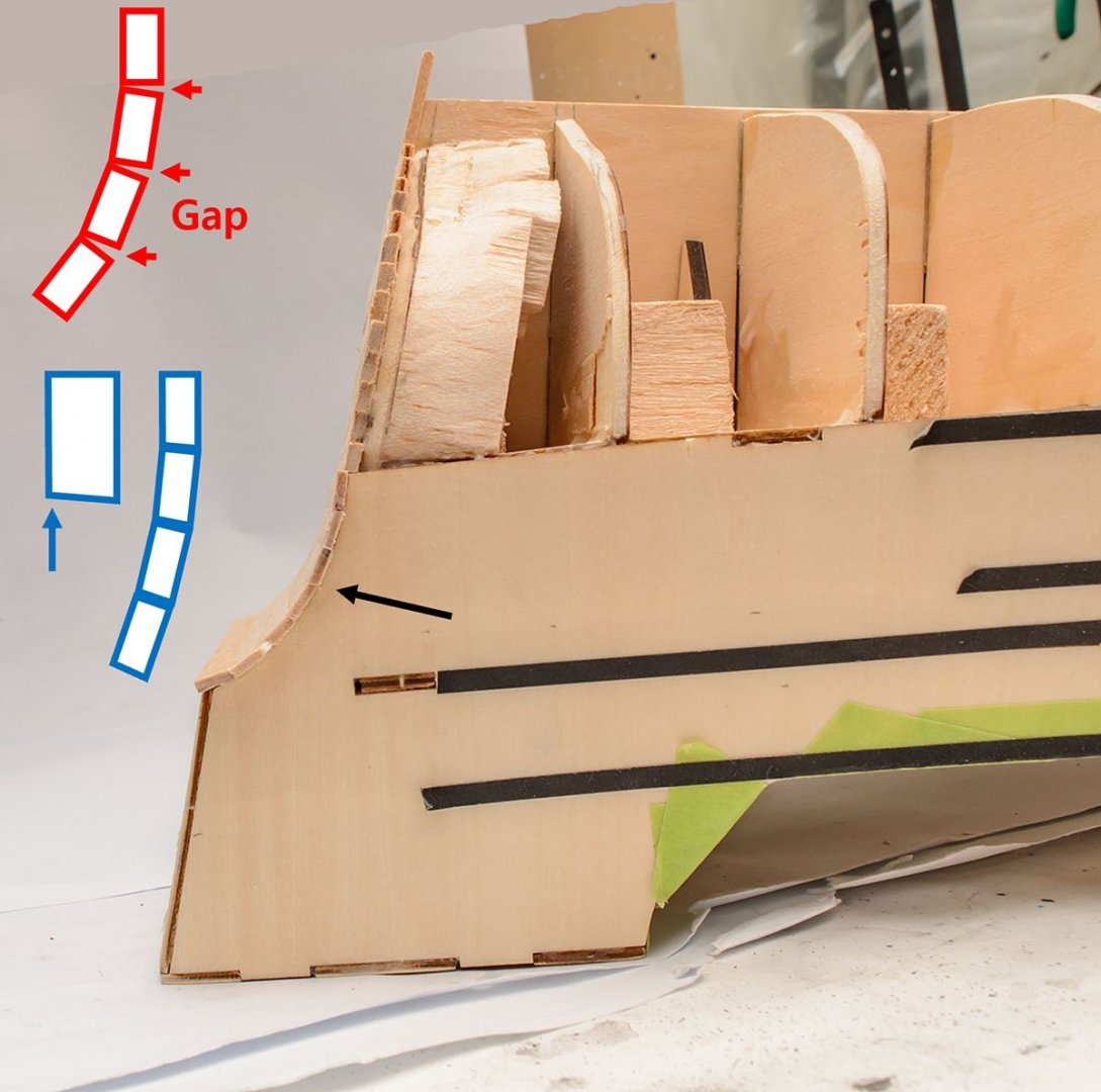
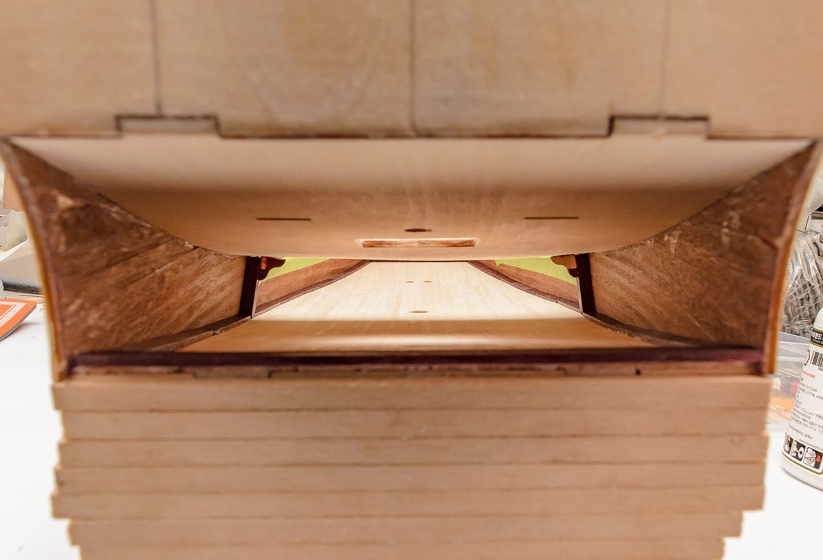
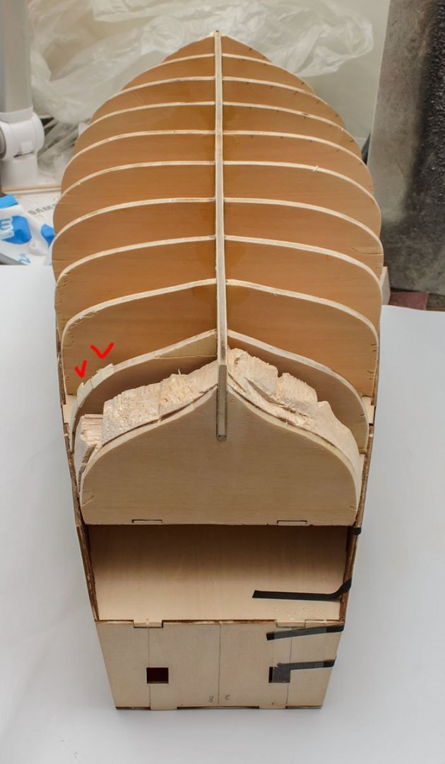
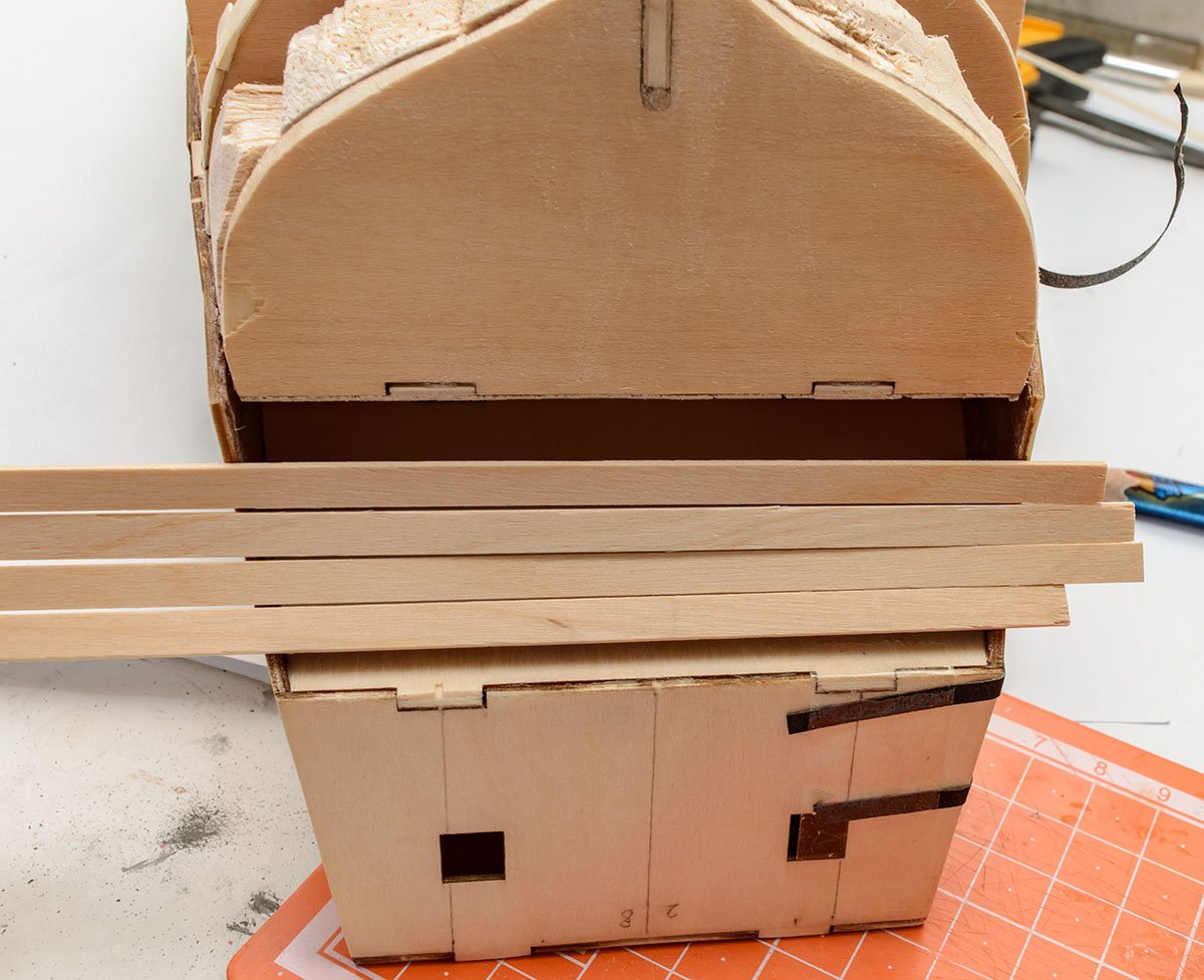
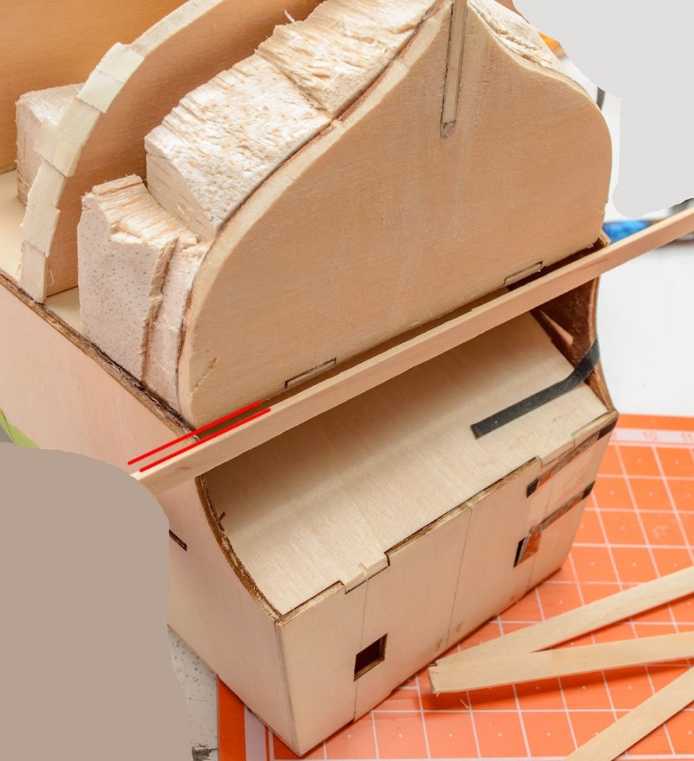
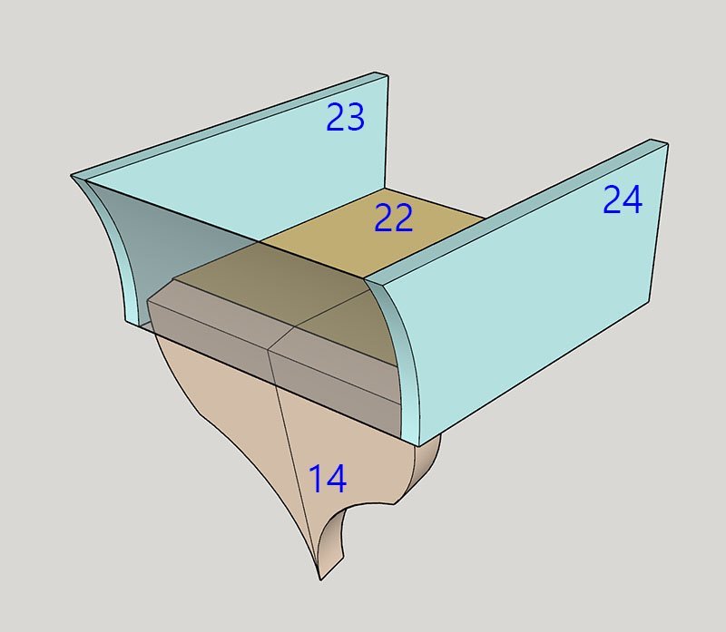
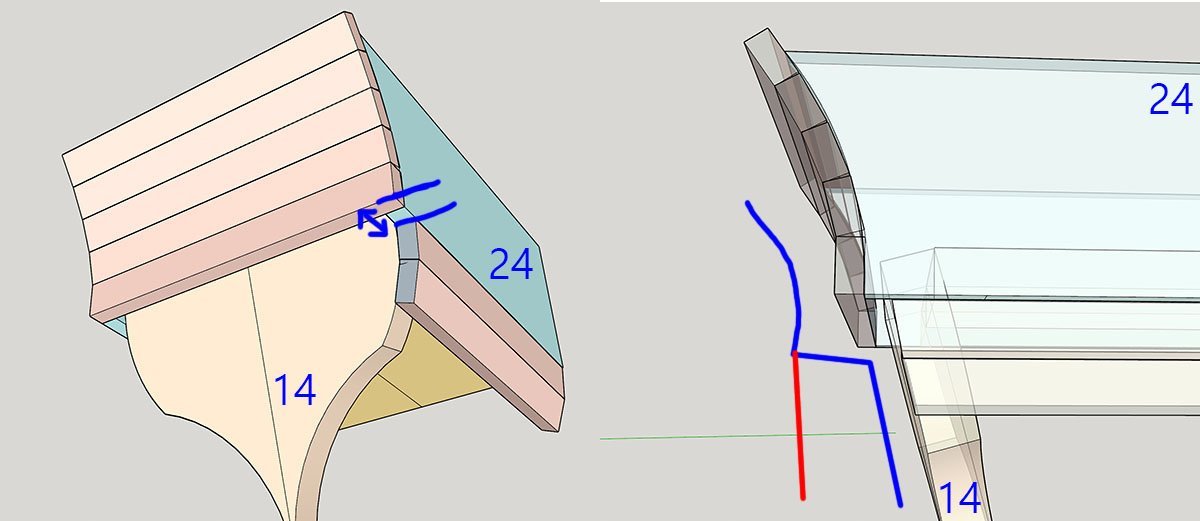
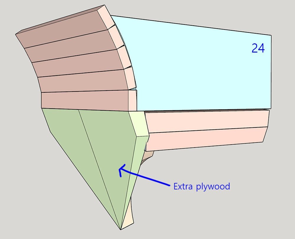
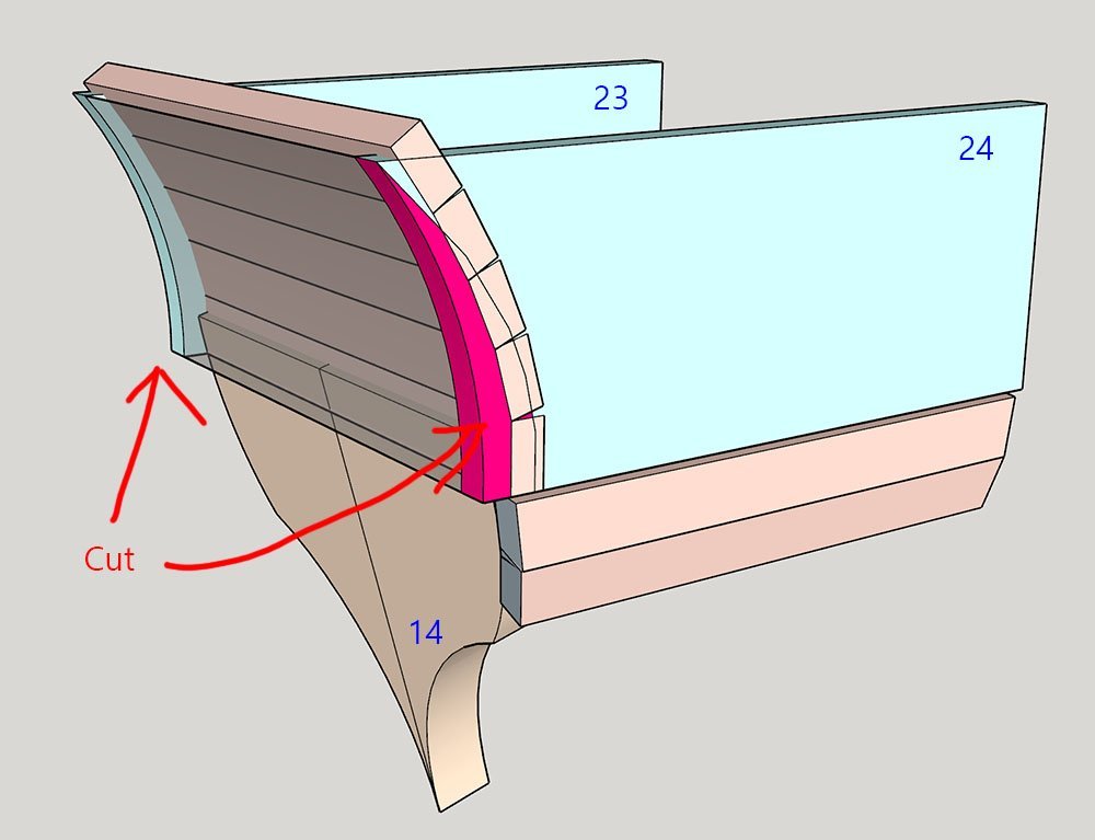
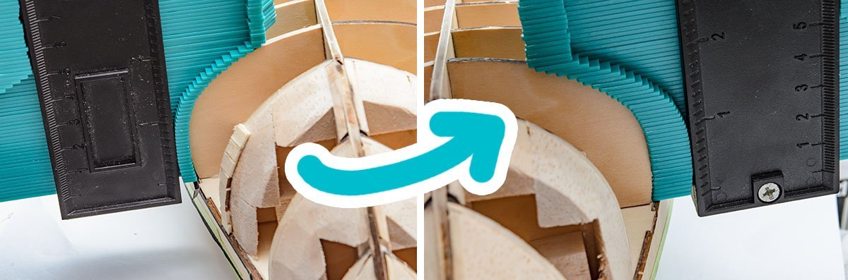
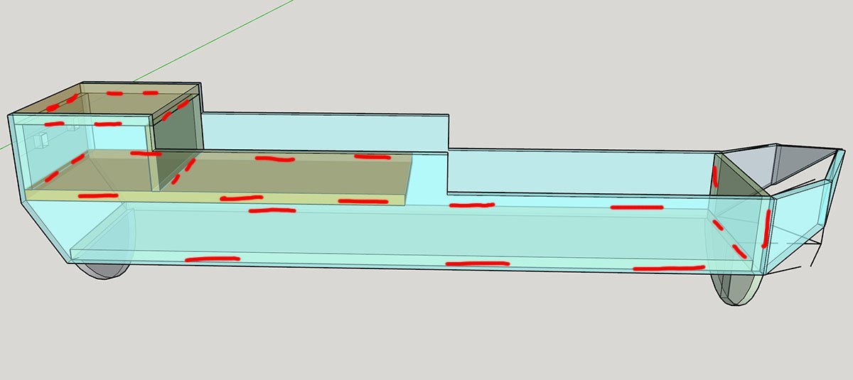
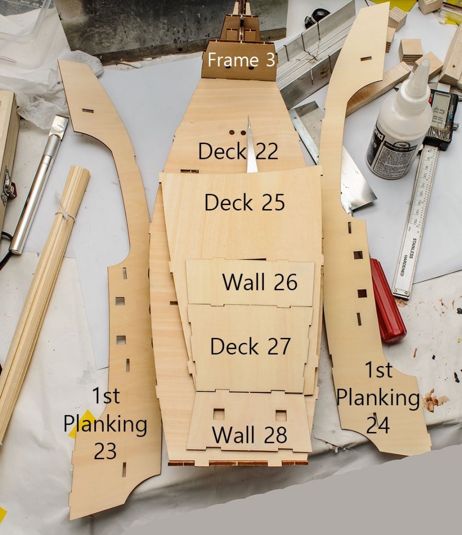
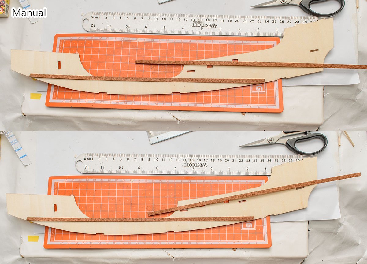
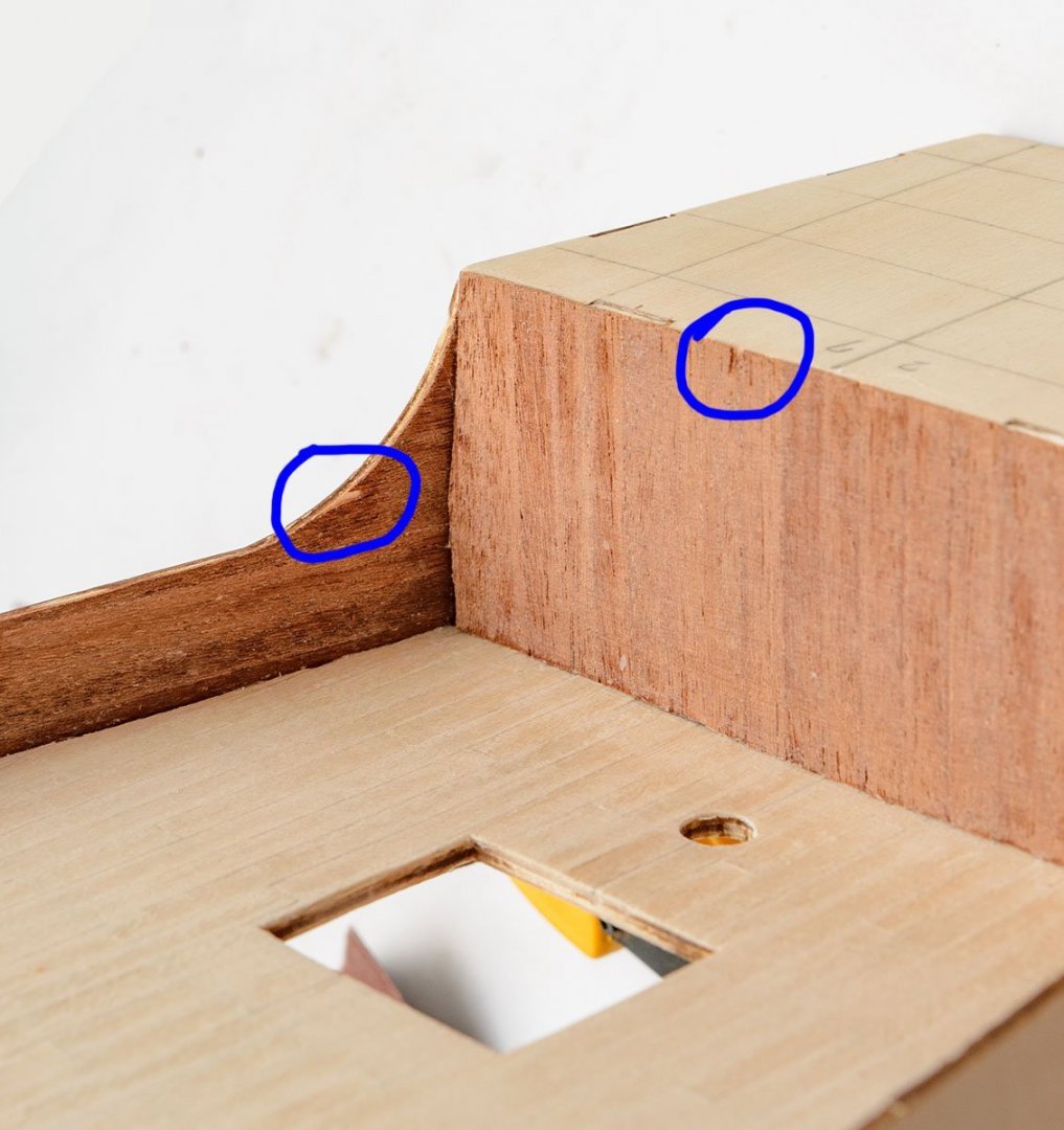
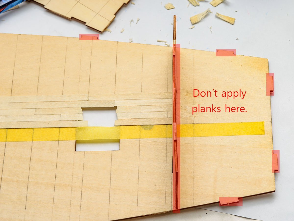
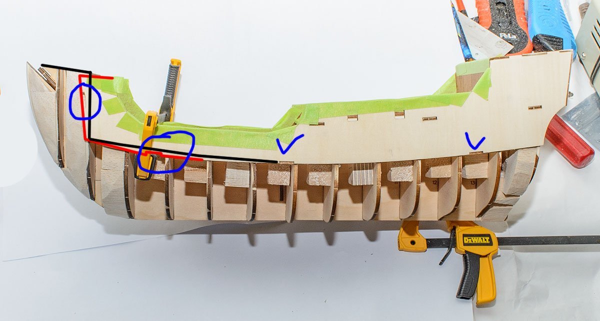
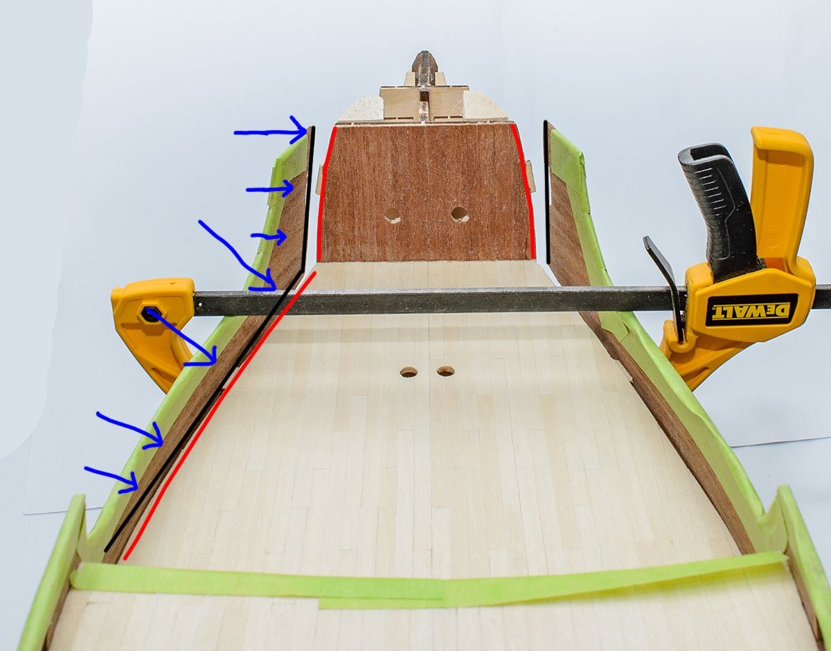
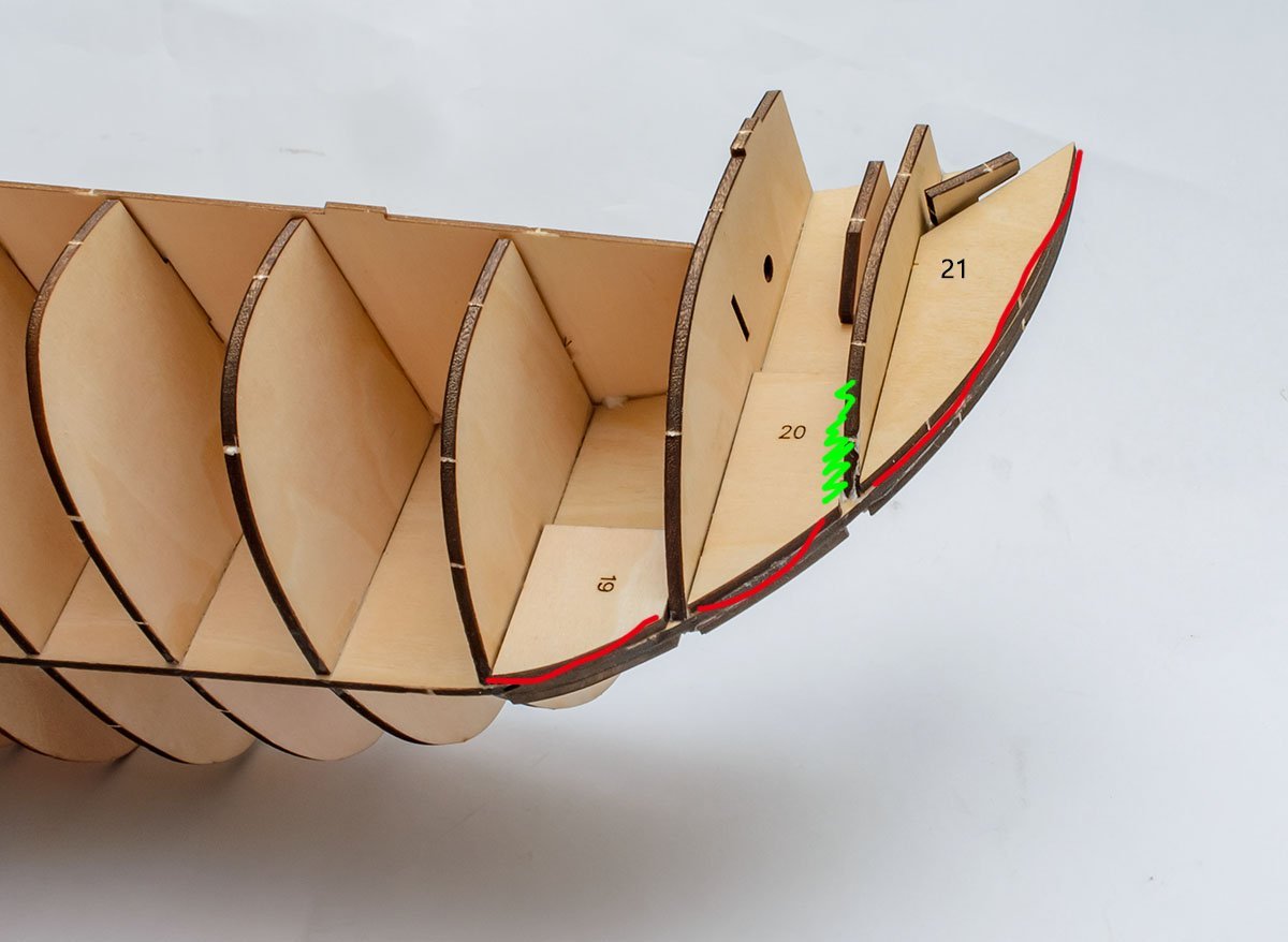
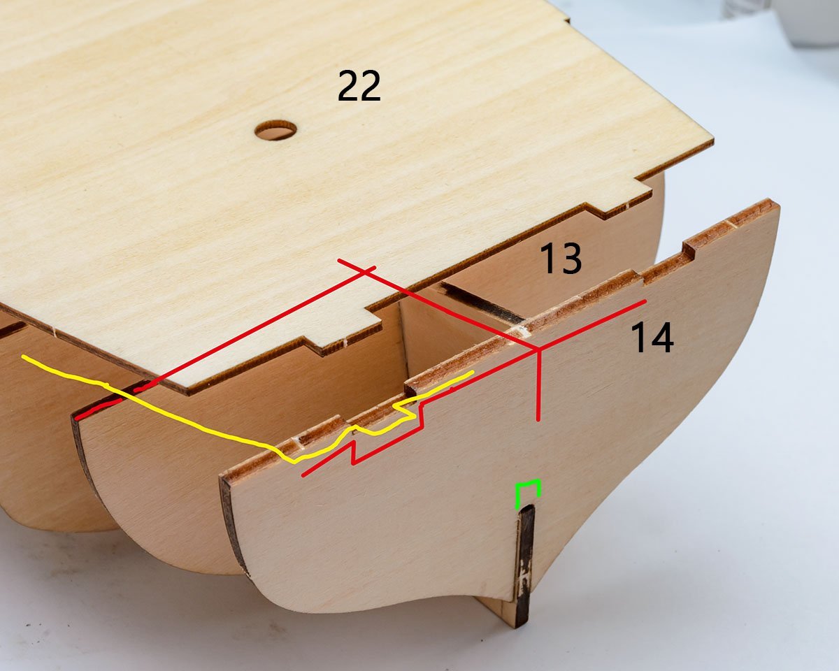
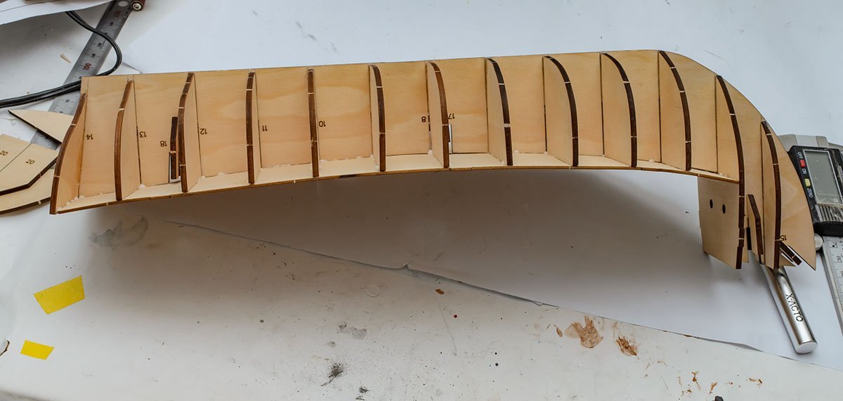
I asked some questions regarding hull fairing, and realized that I made some mistakes. Some of the descriptions I wrote above were repetitive and may be useless for this kit. The process could have been simpler so that I could have saved time and labor for hull fairing when I was installing frames more carefully. Expert modellers already know that my above posts are not organized, and I also warn new builders to take my posts regarding hull fairing with a critical eye. 🧐 I finished hull fairing after a month. It could be a couple of days if I knew my mistakes and eliminated my bad habits. 🤔 You can see that I patched some biased frames due to wrong installation or wrong design of the kit. I found that I should finish the rear planking before the first planking of the hull. And I found another issue. A kit's default setting lets the curve from the blue walls stop at the end of deck 22. There is at least a 2.50mm gap between the walls and frame 14, so the tail line of the hull can't make one simple curve like the red line. I checked an old kit's parts list. The AL reused an old kit's side wall parts 23 and 24 for the new kit without changes. Looks like they believed the old kit was perfect... 😜 I thought about a solution to the issue. The first solution is to sand both side walls more than 2.50mm. It would be a great solution for the new starter, but I've already assembled the parts, and it is hard to sand both walls... This is a second solution that attaches planks to the rear of the frame 14. It is super easy and simple, but may change the hull and keel line and will cause some other fit issues, such as a rudder. I'll try this method. You'll see how it goes wrong. 😂

-
I'm not sure that I understood well, but I've never imagined such an advanced technique to make a reversed mold. It looks really professional and promising. Thank you for sharing the awesome knowhow, Jaager.
-
I forgot it. Thanks, Gregory. Although my kit (AL Santa Maria 22411N) has no paper drawings, I'll use the technique in the next time. By the way, I had had a heavy issue with planking curve lines. The hull's asymmetry was so strong that the waterline on both sides was usually 10mm different, a number of both sides of deck planking are different more than three, and rigging work was also strange. If this isn't a big issue in general, perhaps I should clean up a bad habit. 🤔
-
Hello, I have a question about the shape of the hull before the first planking. Which one is the most accurate way to copy the shape of frames onto the other side? I'm considering three ways, but they have both benefits and downsides. 1. Using the woodwork tool, I can copy the shape of one side of the frame easily. - Weaknesses; Inaccuracy due to difficulties in establishing a base line and insufficient size to measure all curves at once. 2. Determining the length of the frame's edge. Simple. - Weaknesses; I don't know how the curve goes. 3. Adding mutiple guide lines to frames before assemblying. - weaknesses; boring work, hard to check when the gap is filled with balsa blocks. 4. Drawing the outline of the frame using a pencil. - weaknesses; it needs space between frames. Is there a legitimate procedure to make a model ship's hull symmetrical?

-
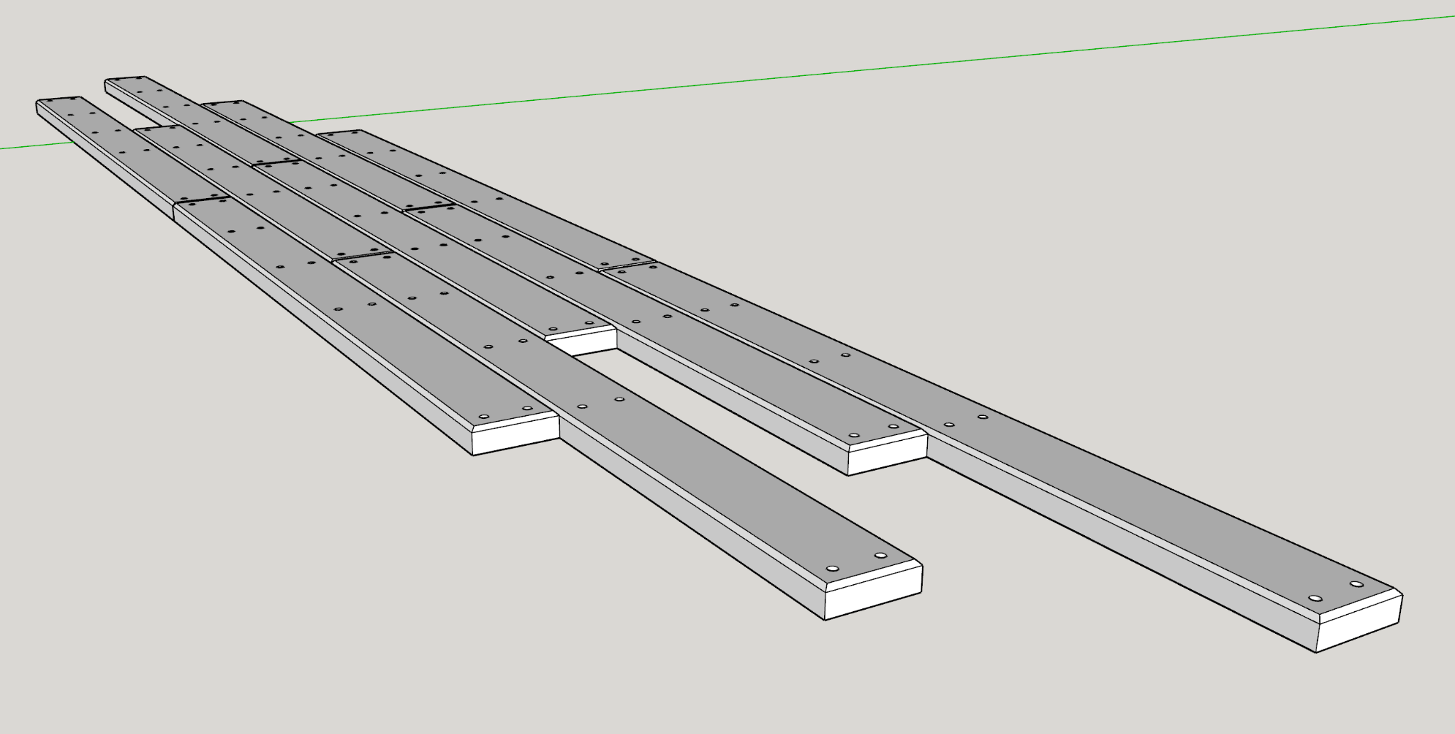
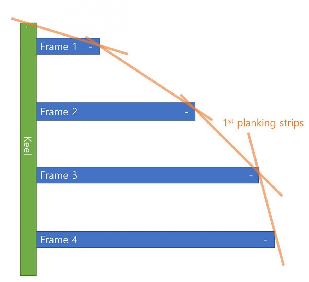
I thought about a better sequence to build the new kit. I call the AL manual's process an accumulation of minor errors. AL manual doesn't explain any direction of hull planking, so people who have no idea about it can build the hull in different shapes. This is a simplified diagram of a keel and frames. There are some joints (red lines) that help keel in a straight line, but there are neither guide lines nor absolute base lines for rest frames. Many new builders including I, may not be able to assemble rest frames like in an instruction. As a result, the hull will accumulate errors as I install frames. On the contrary, the upper structure is very firm and intuitive. There are tons of joints that force each part tightly, so I have almost no option. The new kit increased the number of red joints. The upper structure is very accurate and there is no chance to make an error. The hull may include lots of errors. It is a reason I had trouble. If I followed the manual's order, accumulated errors from the hull will affect the upper structure, and I will have a trouble when I assemble the captain's cabin. It feels like building a stone castle on a flowing sand river or a house of cards. I thought any idea to solve the entire issue, and I changed the order of assembly. This order starts from a firm upper part and ends at a flexible hull part. 😆 This order solves an issue of frame height, too. 😎 I don't have a plan to disassemble my project, and I won't buy the same kit again. I may buy Amati's kit in the far future. Also, I don't guarantee that this order is better than the AL manual's order. You can consider my idea a joke.

- 77 replies
-
- 1
-
-
- Santa Maria
- Artesania Latina
- (and 1 more)
-
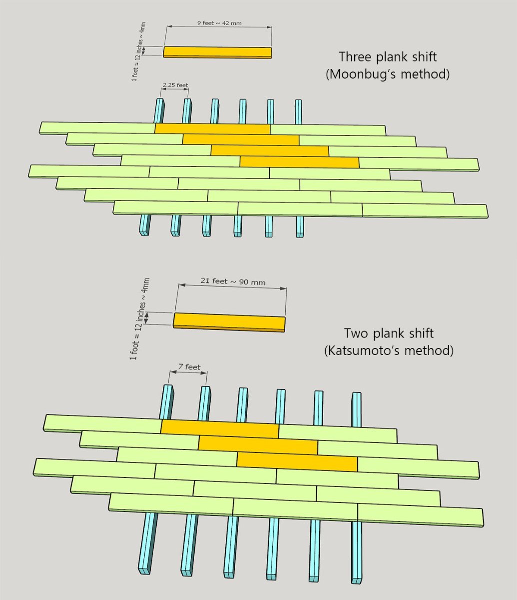
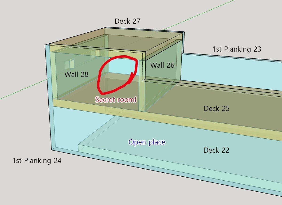
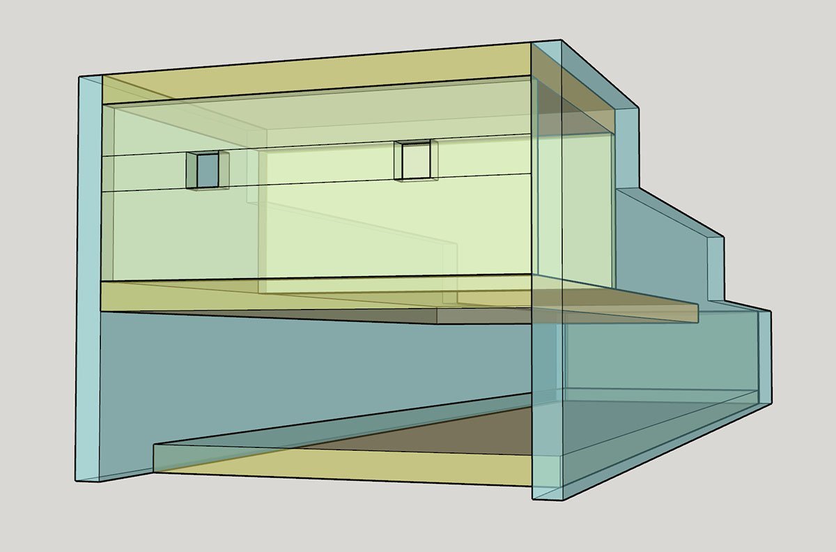
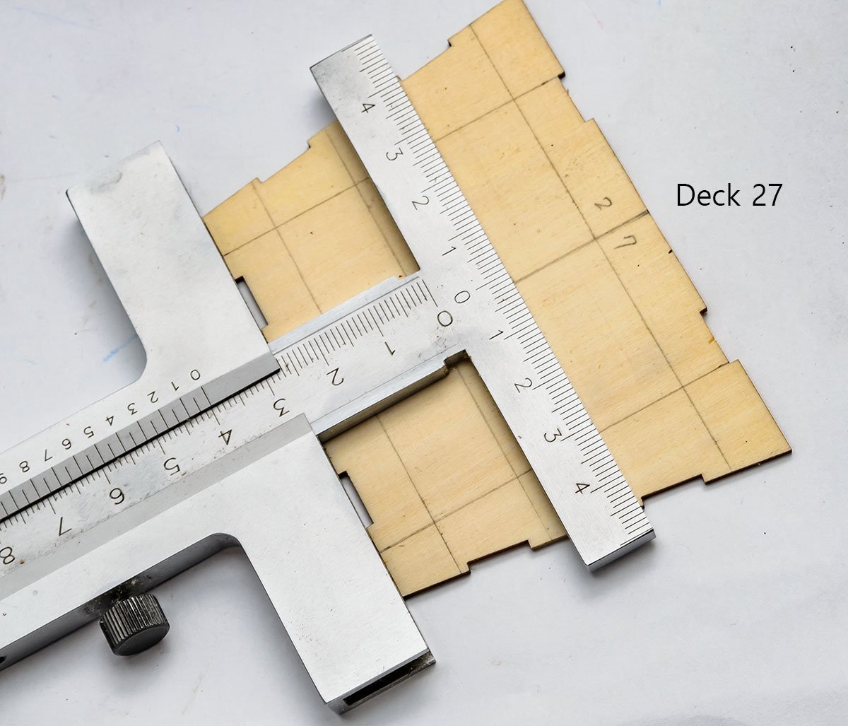
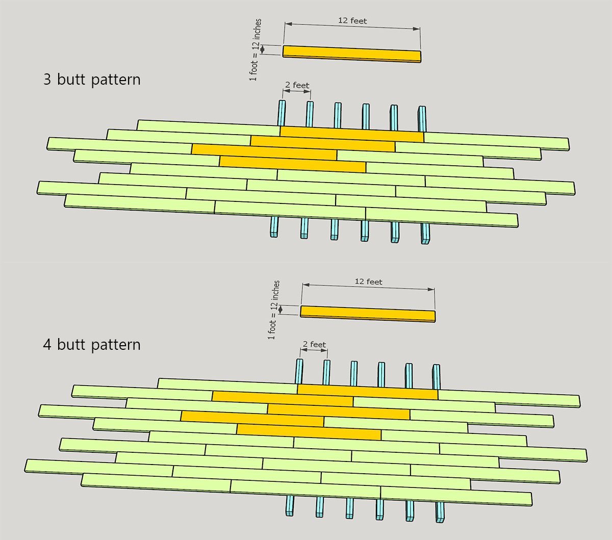
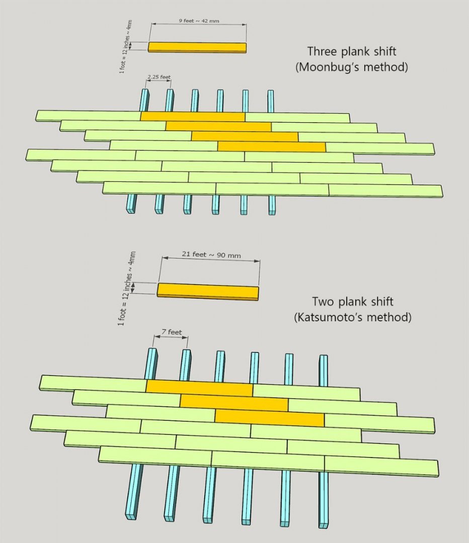
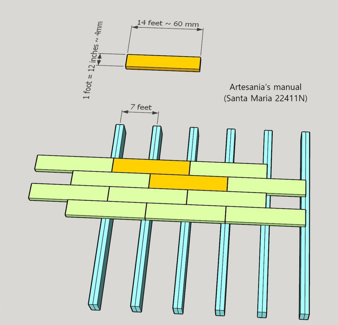
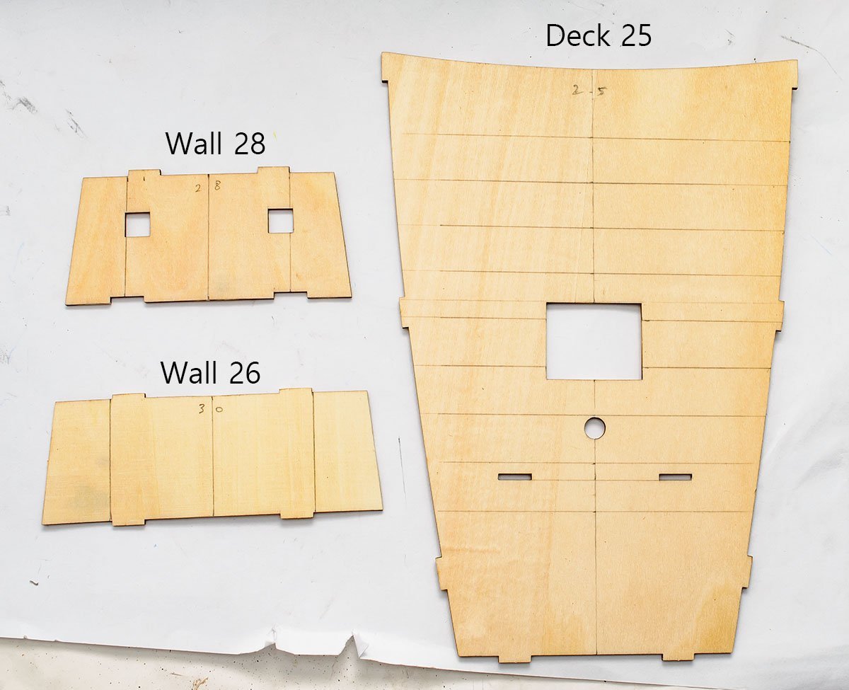
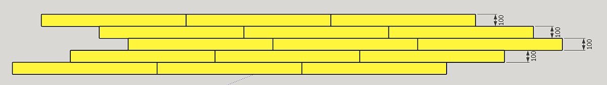
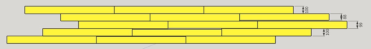
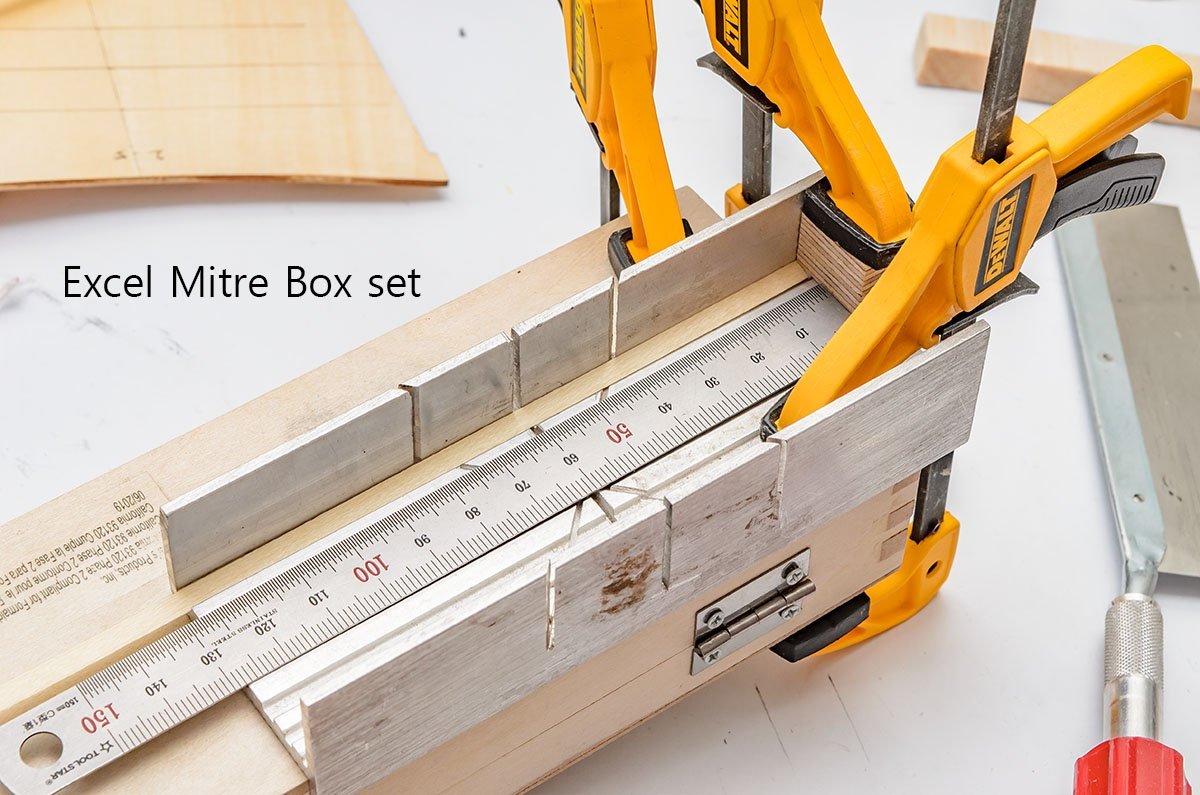
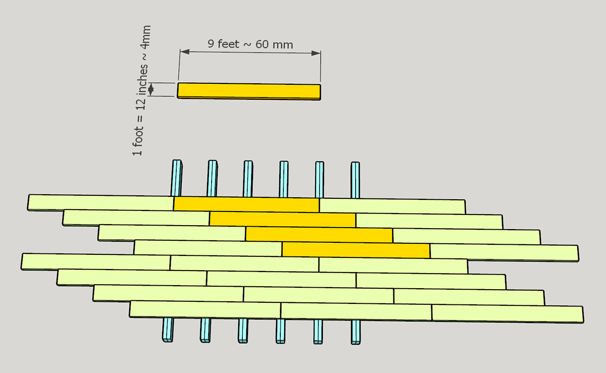
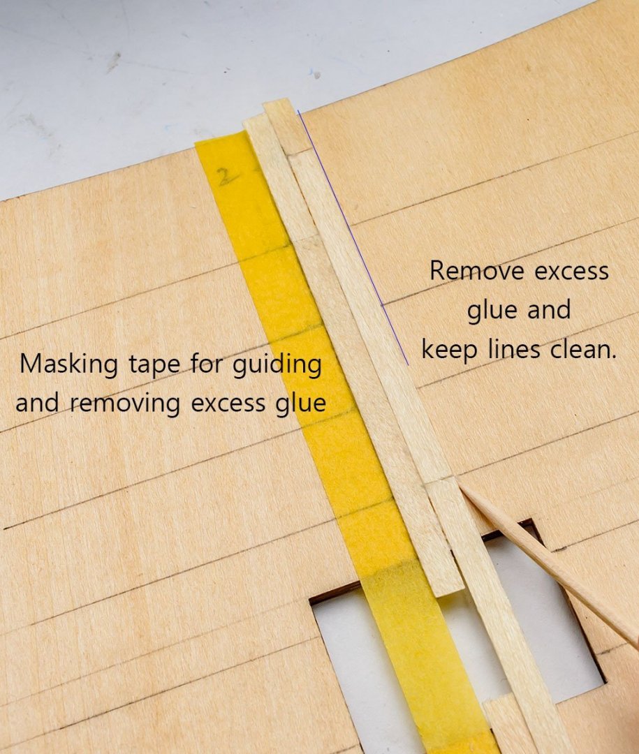
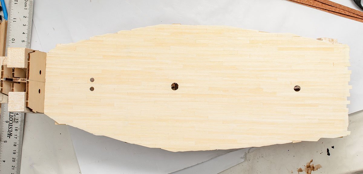
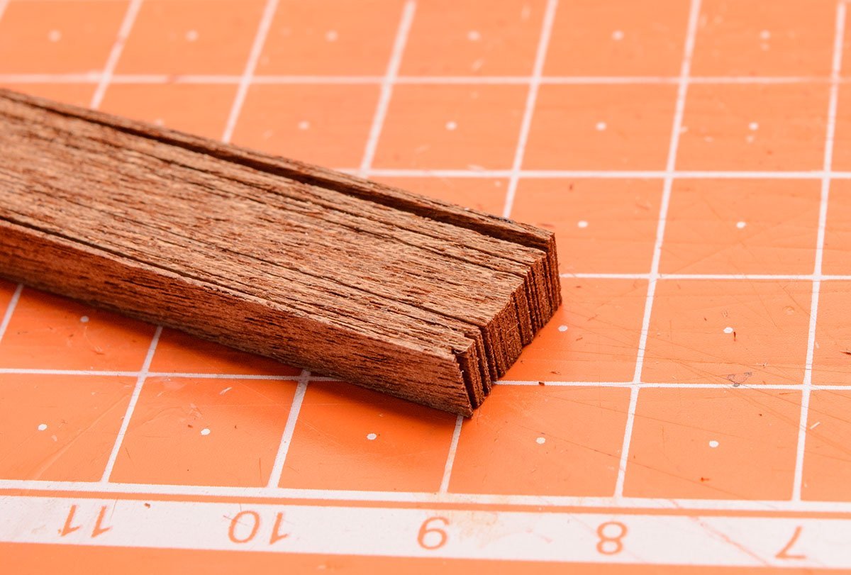
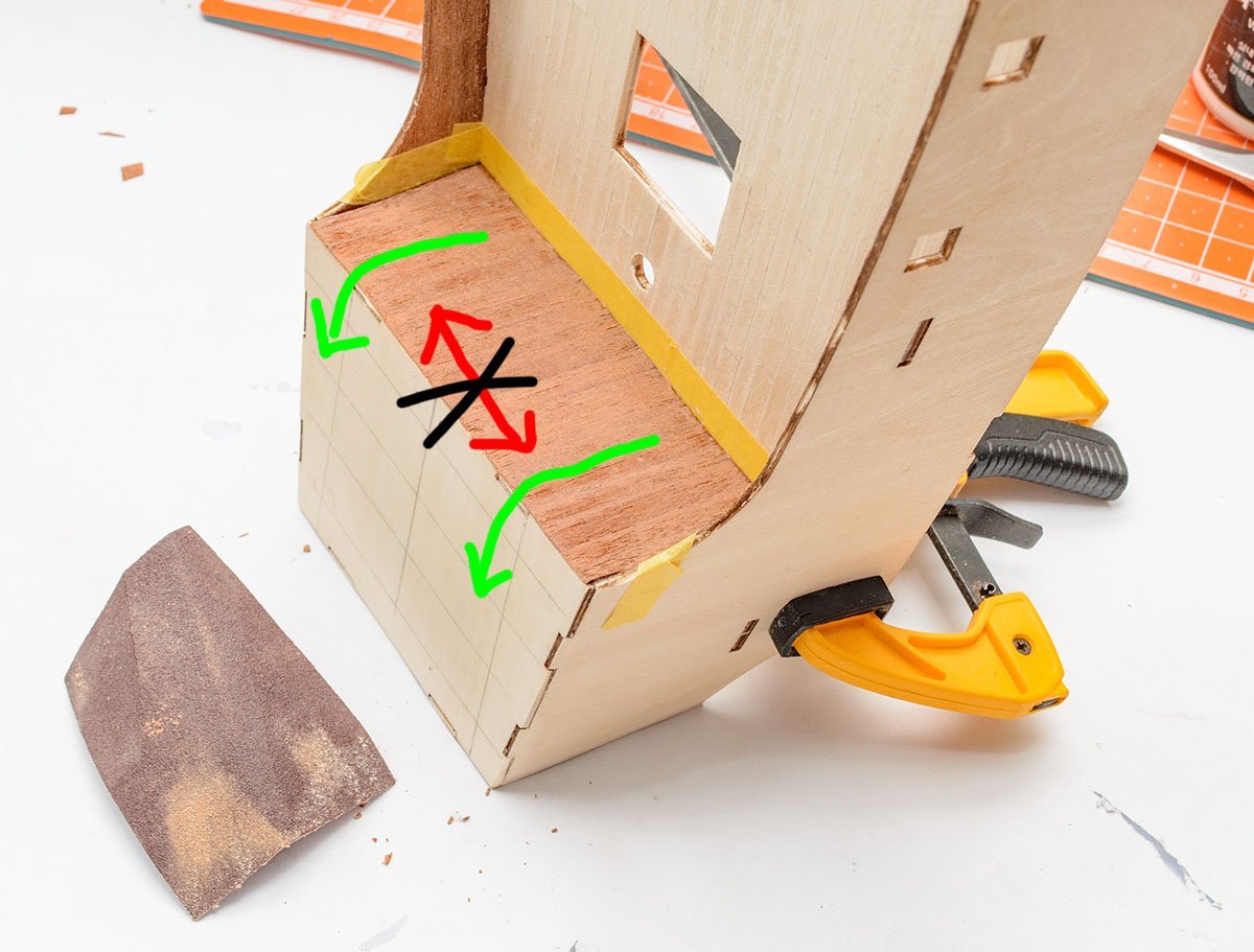
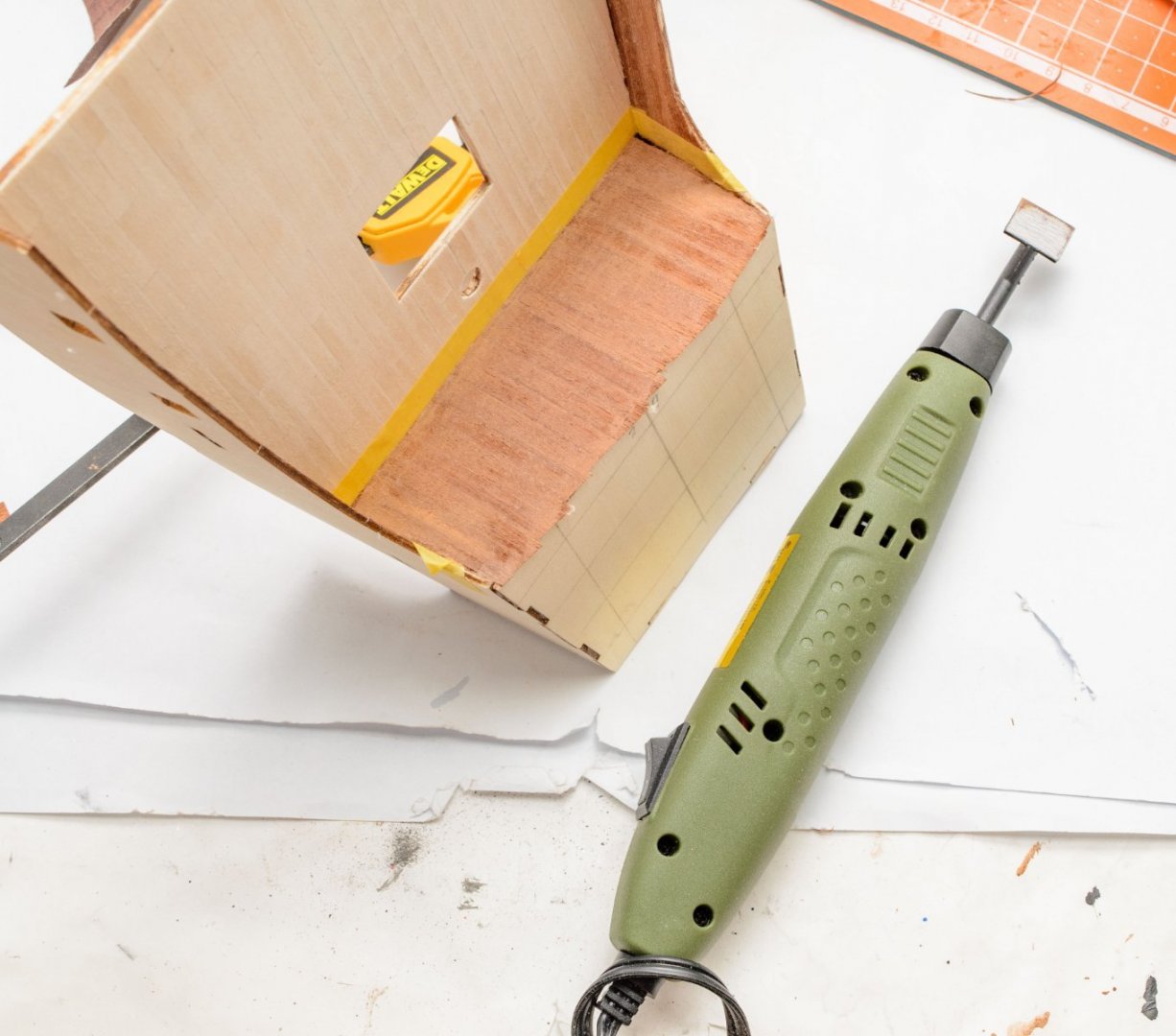
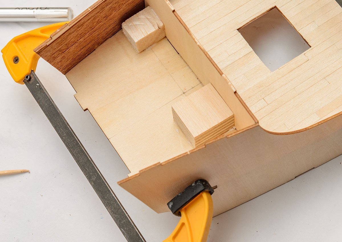
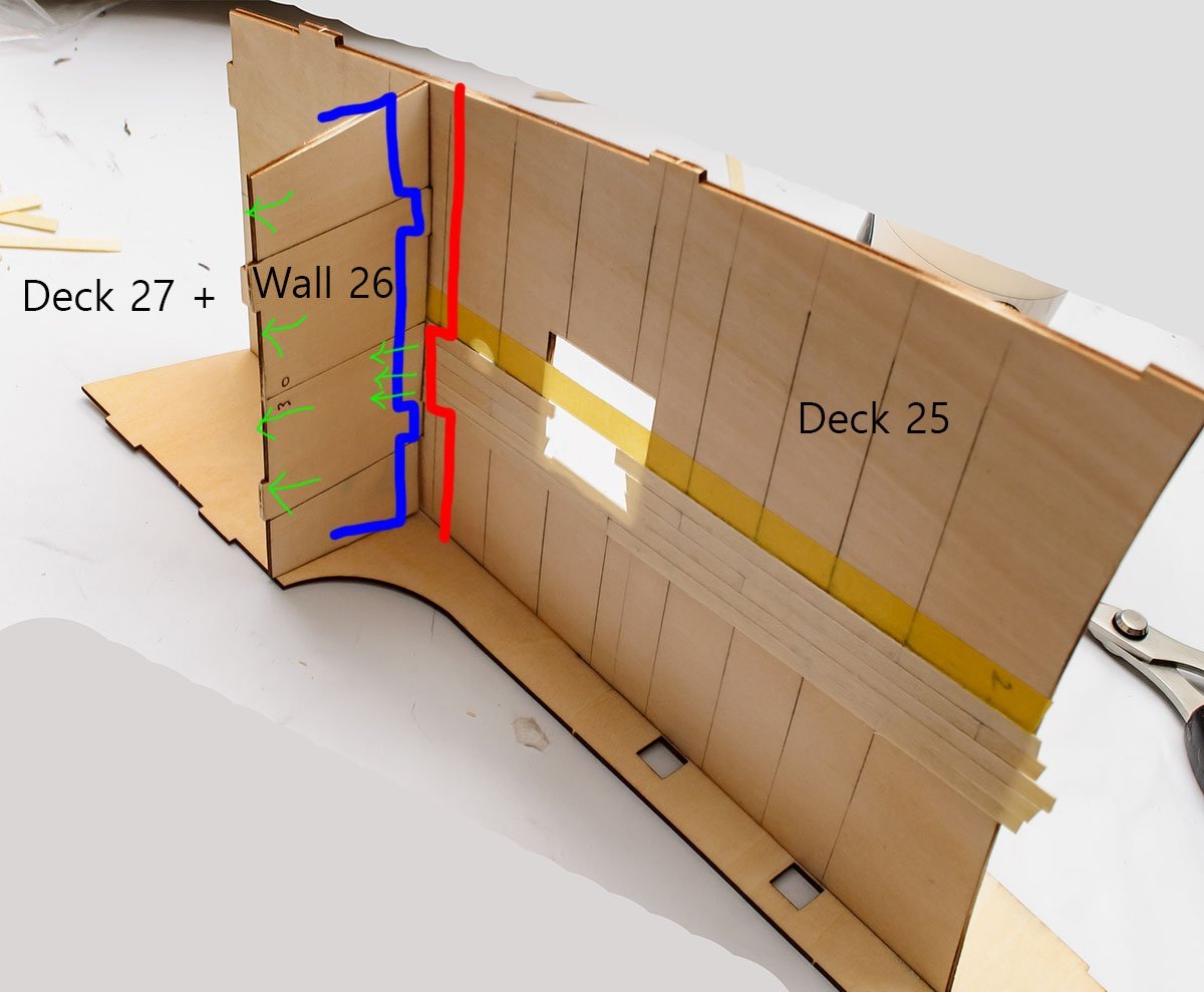
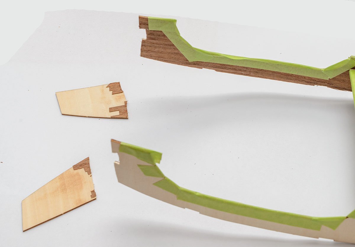
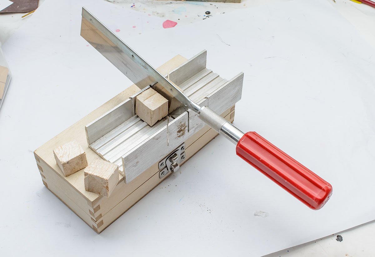
Thanks for kind comment, Dan. I spent weeks researching and writing it. 😂 I said that I finished the upper structure first and attached the bunch to the hull. To complete the upper structure, I needed to do deck planking. These are places I finished last month. I wrote lots of instructions while I was solving the mismatching issue. There are interesting points about this kit. Some builders open the secret room and decorate inside. In addition, you can see the rear of the first floor, which is a great place to hide husband's fund. Before you start deck planking, it is highly recommended that draw base lines on the panels. Draw the center line and beam lines. The 3 butt and the 4 butt patterns are the best known patterns, but the Santa Maria was a ship in the 15th century. These are patterns that Moonbug and Katsumoto used. The old ship might use old pattern. Size of planks and the distance between beams are different, too. Thanks to Moonbug and Katsumoto for giving me a hint. This simple pattern is in AL's manual. I used a three plank shift pattern with 60mm long planks to reduce time. (Moonbug used 42mm strips.) I drew deck planking guide lines according to my plan. My beam width is 15mm. So, how do we get clear and beautiful deck planking? If you are a second ship builder, you may have experienced that first deck planking was likely to be... This!🤪 If you cut strips properly, the only reason for mismatching is the various width of the strips. Old AL kits usually have relatively ragged strips that cause uneven deck and hull planking. In that case, sort the strips and select same width strips only for the same part. Thankfully, the new AL Santa Maria kit has the best quality basswood strips! 90% of strips have exactly the same width as high quality kit brands. There are some 3mm basswood strips, so be sure you have 4mm basswood strips only when you do deck planking. 😎 If you are working on old AL kits or making your own strips, you may trim strips one by one. Because of the too narrow width, there aren't many options for trimming tools. I would like to recommend using a miniature plane or thumb plane. This Veritas block plane is my beloved tool. It is considered the best tool, but it is a bit expensive. You can purchase a cheaper brand of thumb plane starting at $10~. This is a basic way to cut strips up to 60mm. If you need longer strips, buy two mini mitre boxes and connect them. Unfortunately, the excel mitre box has no bolt holes, but some other mitre boxes have bolt holes that simply connect two mitre boxes on wooden table. Place stips one line by one line. As I said, clean deck planking comes from same width. PVA glue also makes thick layer, so remove excess glues after one line of planking. Use slightly more glue. Enough glue helps work, but excess glue will ruin the next line of planking and further painting work. Skim off excess glue each time with a wooden toothpick. Enough glue will hold the strips tightly when you cut the edge strips. Cut them with a new sharp blade carefully. It is difficult to check for excess PVA glue after deck planking. Apply a small amount of water or rub with a damp cloth. Glossy surfaces mean excess glue. Remove them as much as possible with a damp cloth. (Don't apply too much water. It may weaken deck planking.) Sand a surface to make it flat and smooth. 180~240 is enough. I learned it from my previous failure. 😎 The wall of the Santa Maria kit uses walnut strips. Unfortunately, the walnut strips have slightly varying widths. I had to sort and selected the same width strips. Be careful when you send the edge of walnut strips. The walnut's tissue is like thousands of niddles. It is easily torn and ripped apart. Sand the strips in the green direction only. If you want to sand a very tight corner, there are some professional tools at a high cost. 😬 Also, don't forget to attach masking tape to protect nearby walls! This is the main wall of a ship. The manual said to cover the entire wall parallelly, but I did some tricks. Nobody can't see the green area after I build a ship. Therefore, I installed strips carefully on opened place only. 🤪 I reinforced the captain's cabin with wooden blocks. After I finished deck and wall planking, I found that the walnut planking was already torn. I knew it from previous experience, and it will only get worse with time. I attached masking tape to the model to protect the edges strips. The masking tape for the model is a weak adhesive with no gum after removing it. Don't use conventional tape that will rip off walnut strips at once. Here is another issue. I found that a deck planking of a second floor increase the level of wall 26. It means the third floor (Deck 27) doesn't fit the notch. Therefore, I had to cut the deck planking after installing it. It is easy to remove them; make a cutting line using an art knife, and apply a small amount of water. Push the detached pieces of plank after a minute. It looks like I caught all the past stories. I'll continue the build log from the first planking. 😎 PS. Fixed tons of grammar errors. 😱
- 77 replies
-
- 1
-
-
- Santa Maria
- Artesania Latina
- (and 1 more)
-
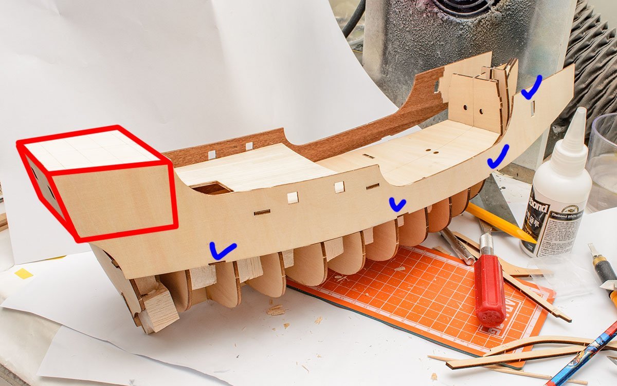
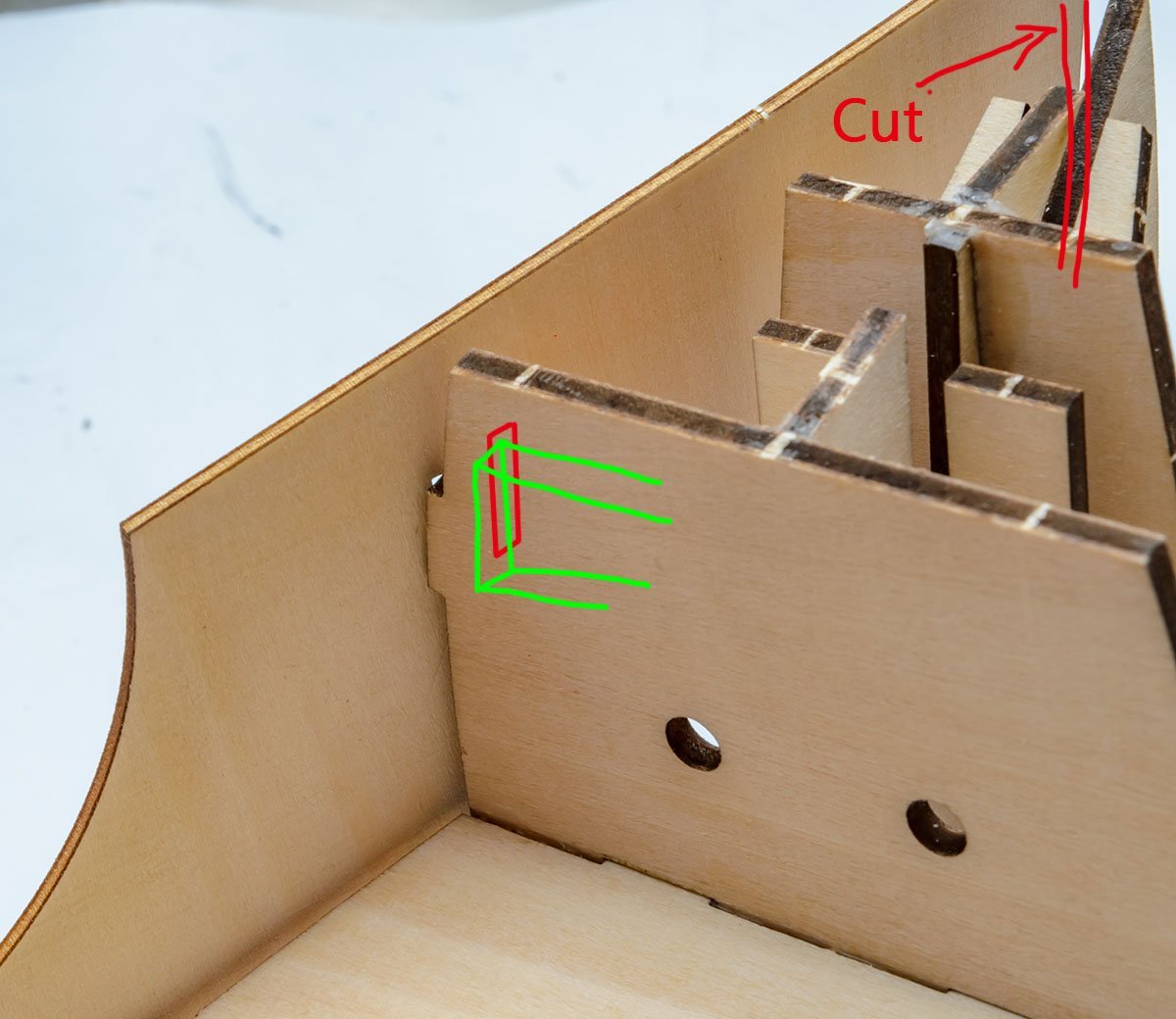
I spent lots of time correcting upper structure part. It is a main reason I didn't continue the build log for weeks. I assembled the captain's cabin. (Red box) A mechanical notch makes the room perfectly square, so I set it as the base line. In addition, I was confident about hull assembly. Therefore, I assembled the upper structure separately, and tried to attach the bundle to the hull like an accurate plastic kit. I believed it was an accurate kit. It didn't work. At first, I thought I hadn't assembled the frames and deck in the proper way. The blue slots are partially fit, and the head side's error was unacceptable. I cut the most significantly twisted part. I couldn't assemble it. At least I can recover it with extra planking strips... In addition, I had to force it when I glued. I felt a lack of hands, and assembly wasn't possible without woodworking clamps. There are too many curves in 3 dimentional directions. It means something is wrong - an assembly error or a kit design error. I really missed the simple HHP kit... Last month, I couldn't find any clues of mismatching, and thought it was my fault. Now I would like to say that AL misdesigned the keel and frames. AL changed the keel but reused the frames without adaptation. As a result, the height of the frames caused deck deformation and the upper structure's mismatching. ( source : https://unsplash.com/photos/4L-AyDJM-yM?utm_source=unsplash&utm_medium=referral&utm_content=creditShareLink ) Even if I followed AL's manual step by step, I would have faced distorted captain's cabin or sloping walls as floors go higher. AL've always been like that. I've made three AL kits with their kind manual, and encountered mismatching issues or asymmetry hulls. I would say that it is an accumulation of minor errors. AL's instruction is the easiest for new builders. Anybody can follow the step by step, and the plan is likely to work well. Imagine walking in a straight line while looking at the tip of toes through a snowy field. It feels easy and simple, but when you turn your head at some point, the footprints on the snowy field aren't straight lines. As a ship gets more complex, I get more chances to be wrong and can't follow AL's manual anymore. Each AL kit and stage - foot step - has different base lines, so I have to keep my attention sharp every time to follow the kind manual properly. The experiences are too fragmented. There is no place to use my previous experiences when I build a new kit. ( source : https://unsplash.com/photos/4L-AyDJM-yM?utm_source=unsplash&utm_medium=referral&utm_content=creditShareLink ) On the contrary, the traditional planking method I've learned from Toni's Half Hull Planking kit is walking towards a destination. It is hard to swallow the entire idea quickly, but when I learn an insight that looks far away, I don't hesitate to run anymore, and my footprints are in a clean straight line. I can apply the same method to any kit freely, and I don't even need to see a manual frequently, unlike plastic model kits. It is difficult to learn and time consuming, but fun, simple, broad application, and the best result. This is just my private complaint. Senior modellers should have better insight and my idea will change as I build more kits. My only wish is that many kit manufactures include full instruction on planking instead of a picture of sanding frames.


- 77 replies
-
- 2
-
-
- Santa Maria
- Artesania Latina
- (and 1 more)
-
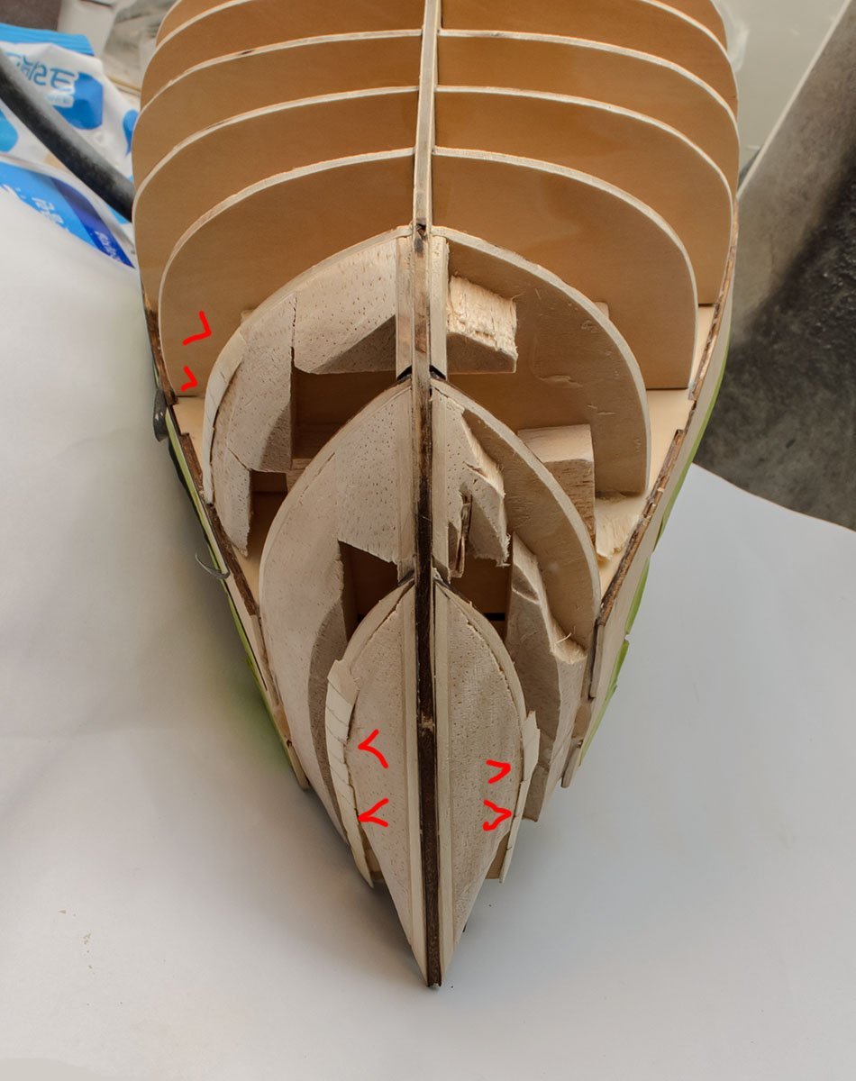
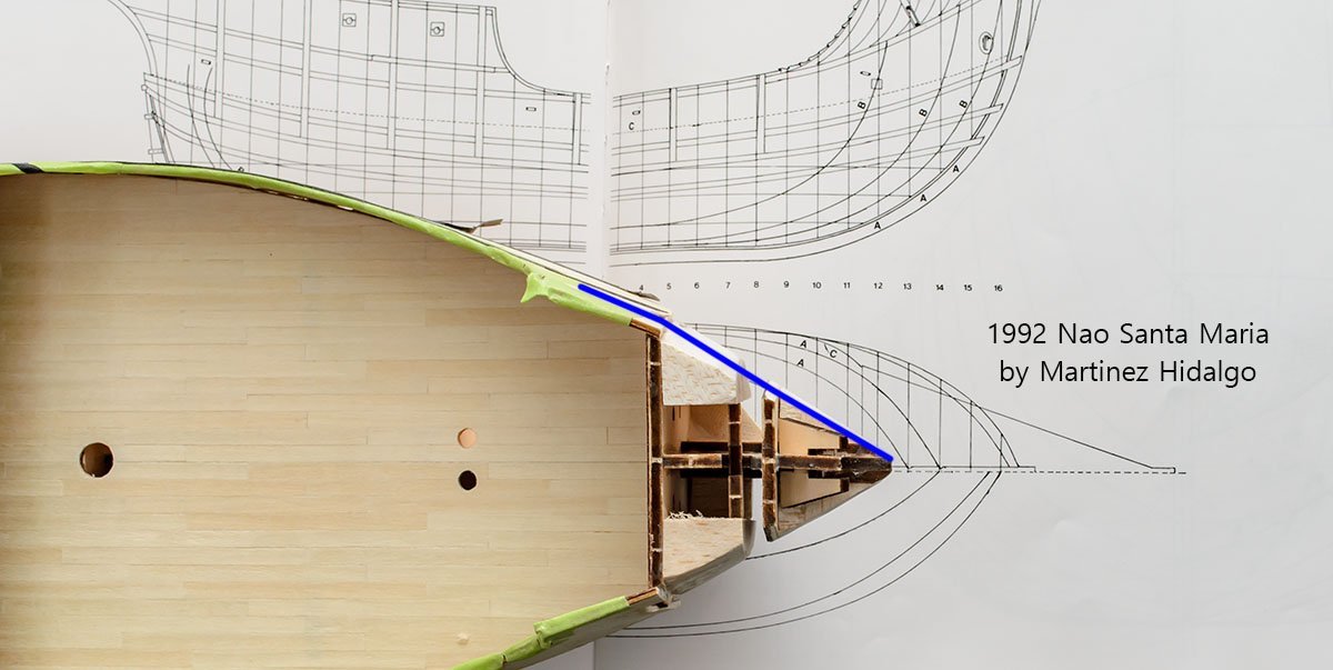
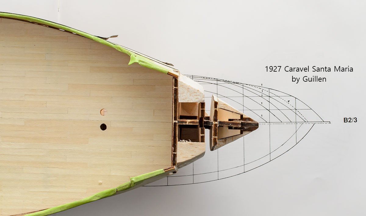
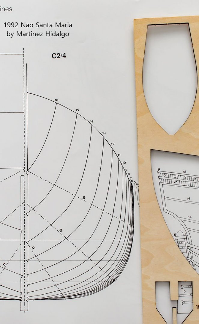
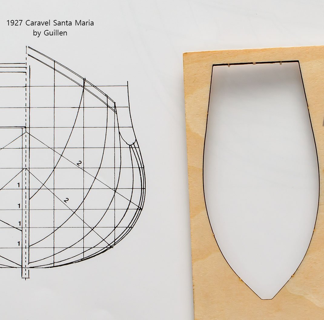
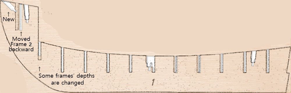
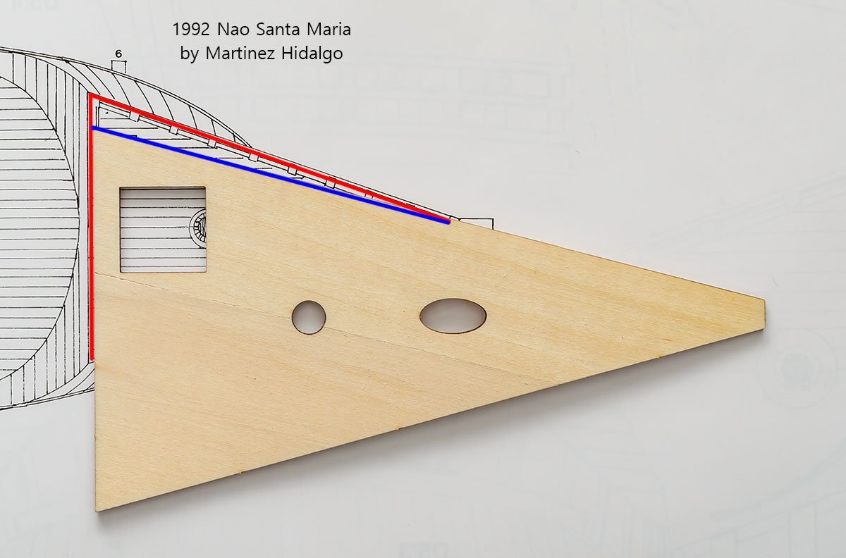
I love Santa Maria's 'chubby' hull. When I was sanding head frames 1-2-3, I felt that the ship's head was too sharp. I had to cut 'chubby' balsa blocks again and again, and decided to research it. As you see, the new Santa Maria 22411N kit has a different stern line to compare with the 1992 Nao Santa Maria. It looks like the 1927 Caravel Santa Maria. Quite odd... Well, it's nonsense that the new 'Nao' kit has a caravel's head line. I double checked the old 22411 kit. The result was surprising. The new kit modified the old kit's keel slightly. When AL added the new foremast hole, they moved the slot for frame 2 backward. As a result, the hull shape is changed. The new kit has more straight planking lines than the old 'chubby' kit. Why? AL didn't change the size of the frame 2! They simply shifted the frame 2 backward! Also, you can see that the height of some other frames' slots is changed while the actual frame parts are not changed. I guess it is a reason why it twists deck and upper structure parts. I'll explain the defect soon. Did the narrower head affect the head gallery? No. the old kit's head gallery uses the same triangle with a thicker neck. By the way, both AL Santa Maria kits are different from the 1992 Nao Santa Maria plan. Consequently, I ignored 'flat head planking', and am following the AL manual faithfully. You'll see the new kit's promotion at the end. 😎
- 77 replies
-
- 1
-
-
- Santa Maria
- Artesania Latina
- (and 1 more)
-
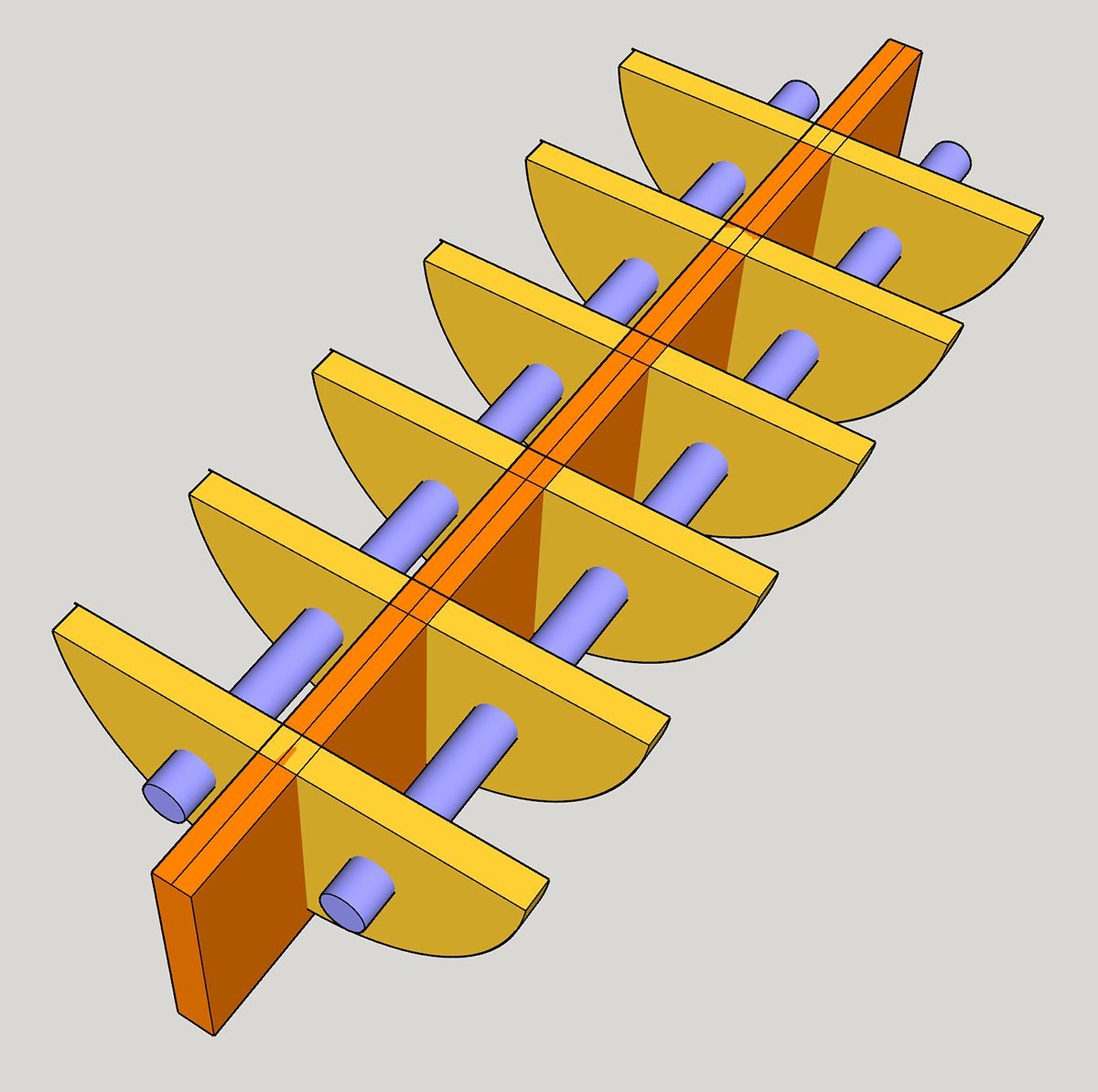
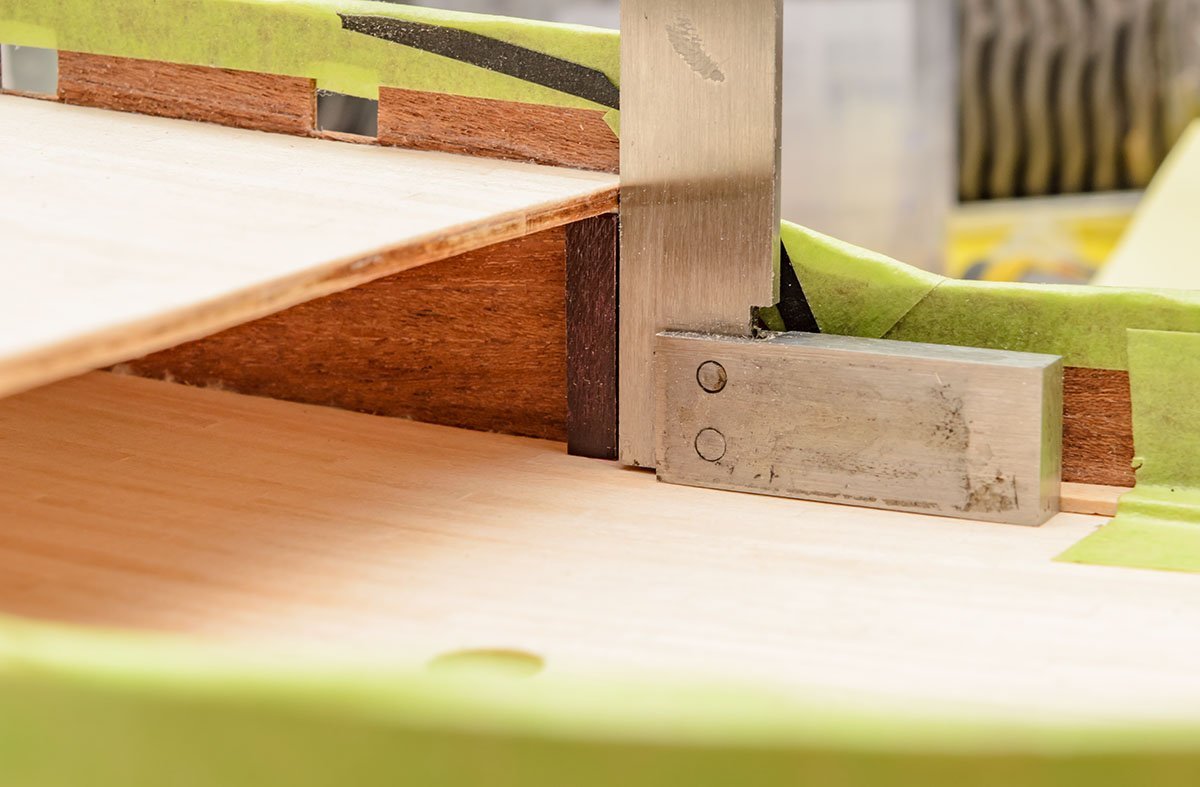
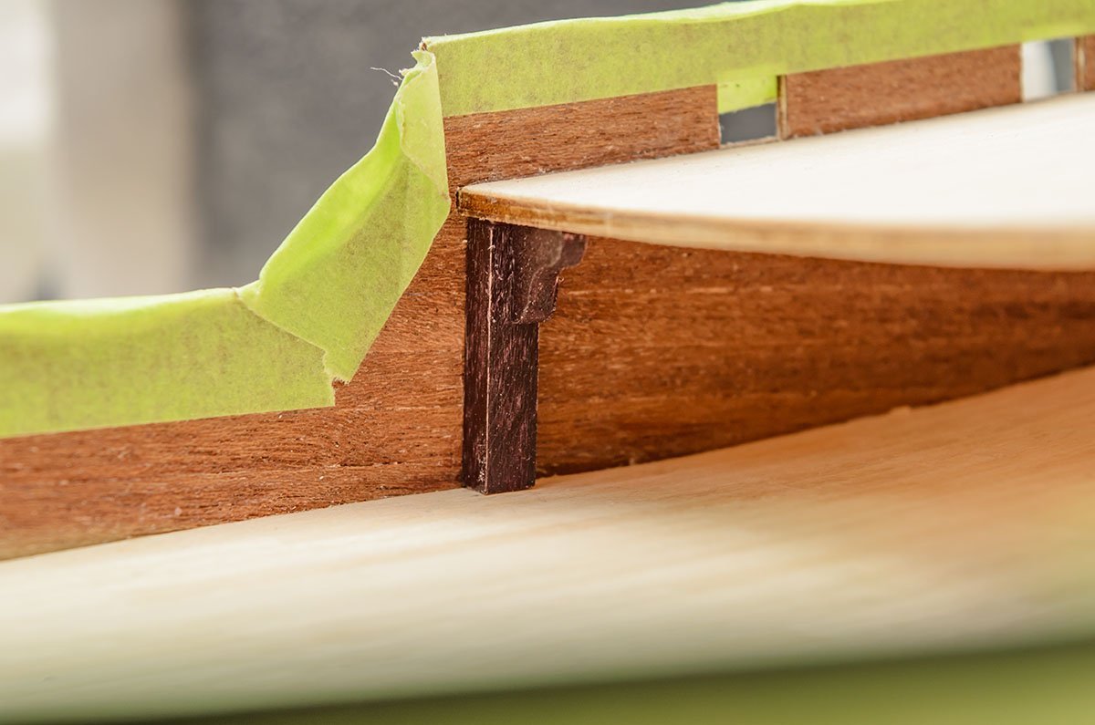
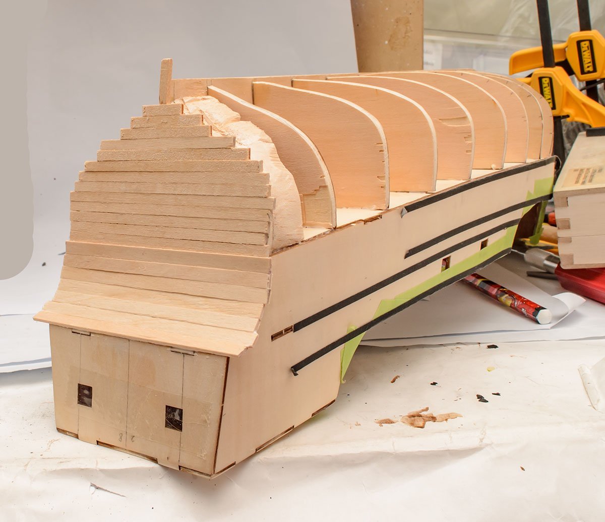
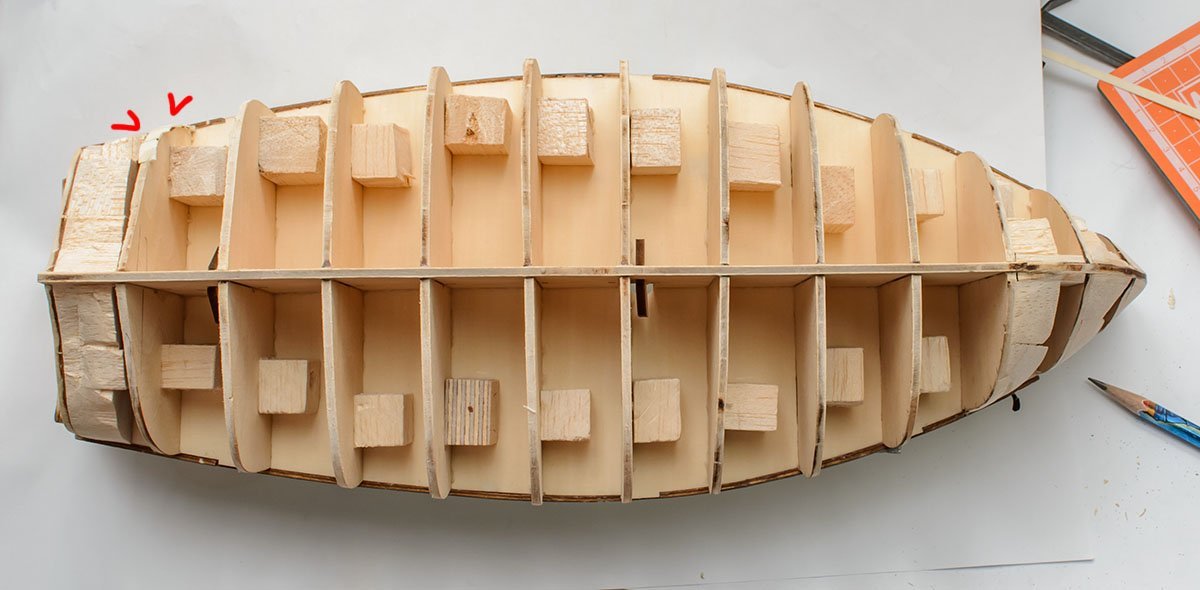
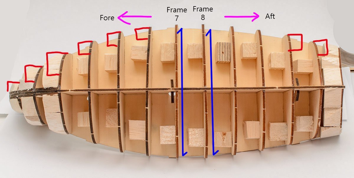
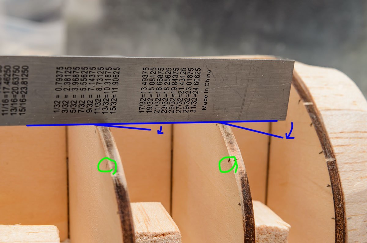
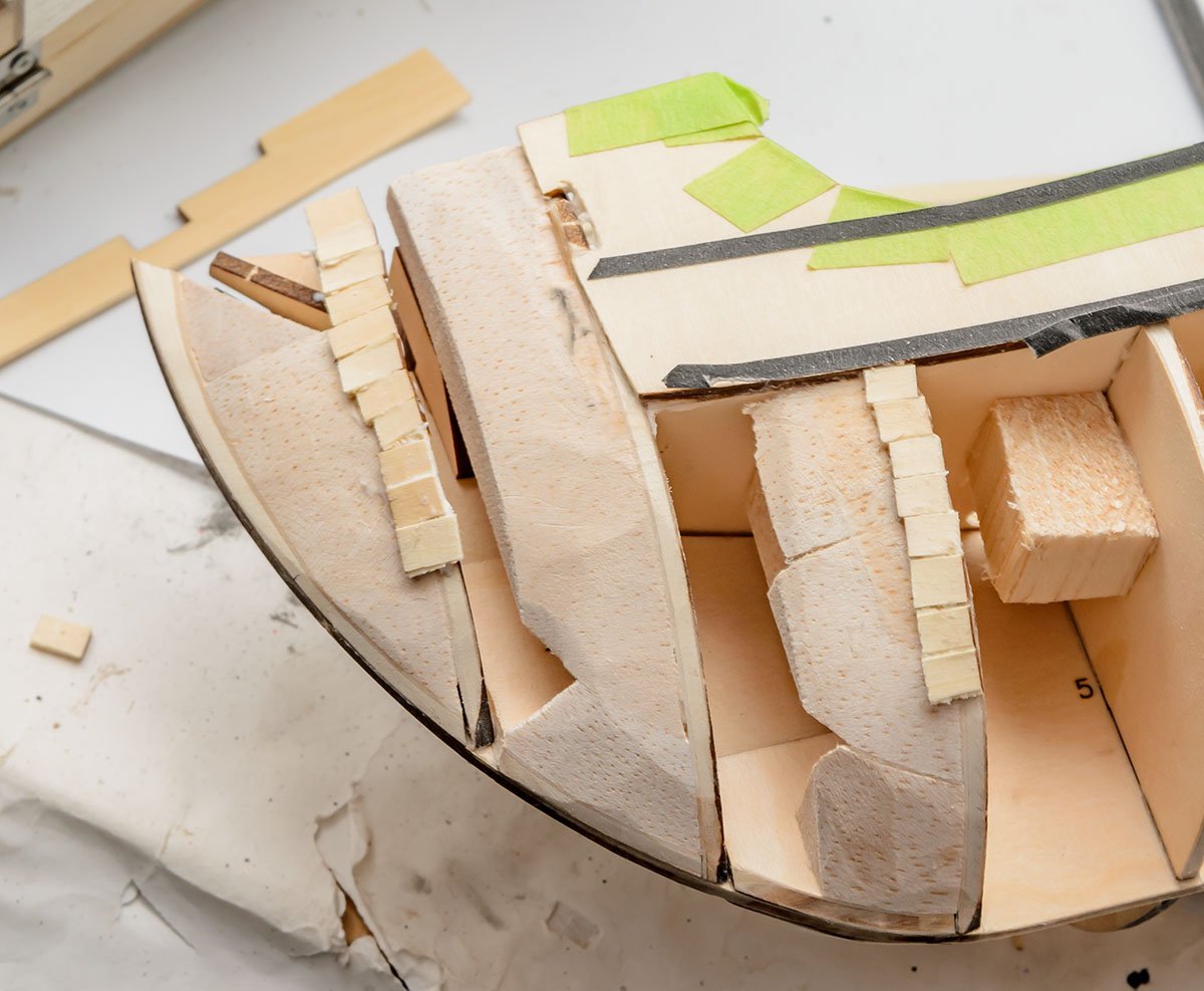
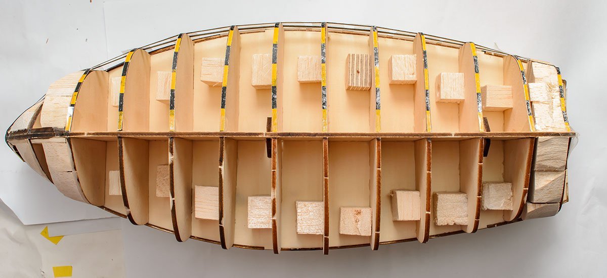
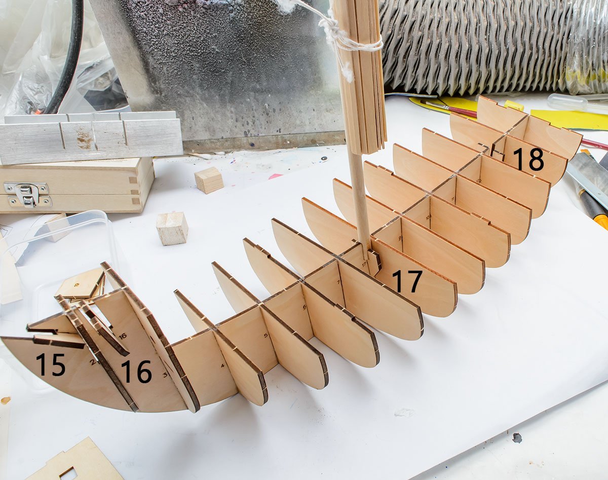
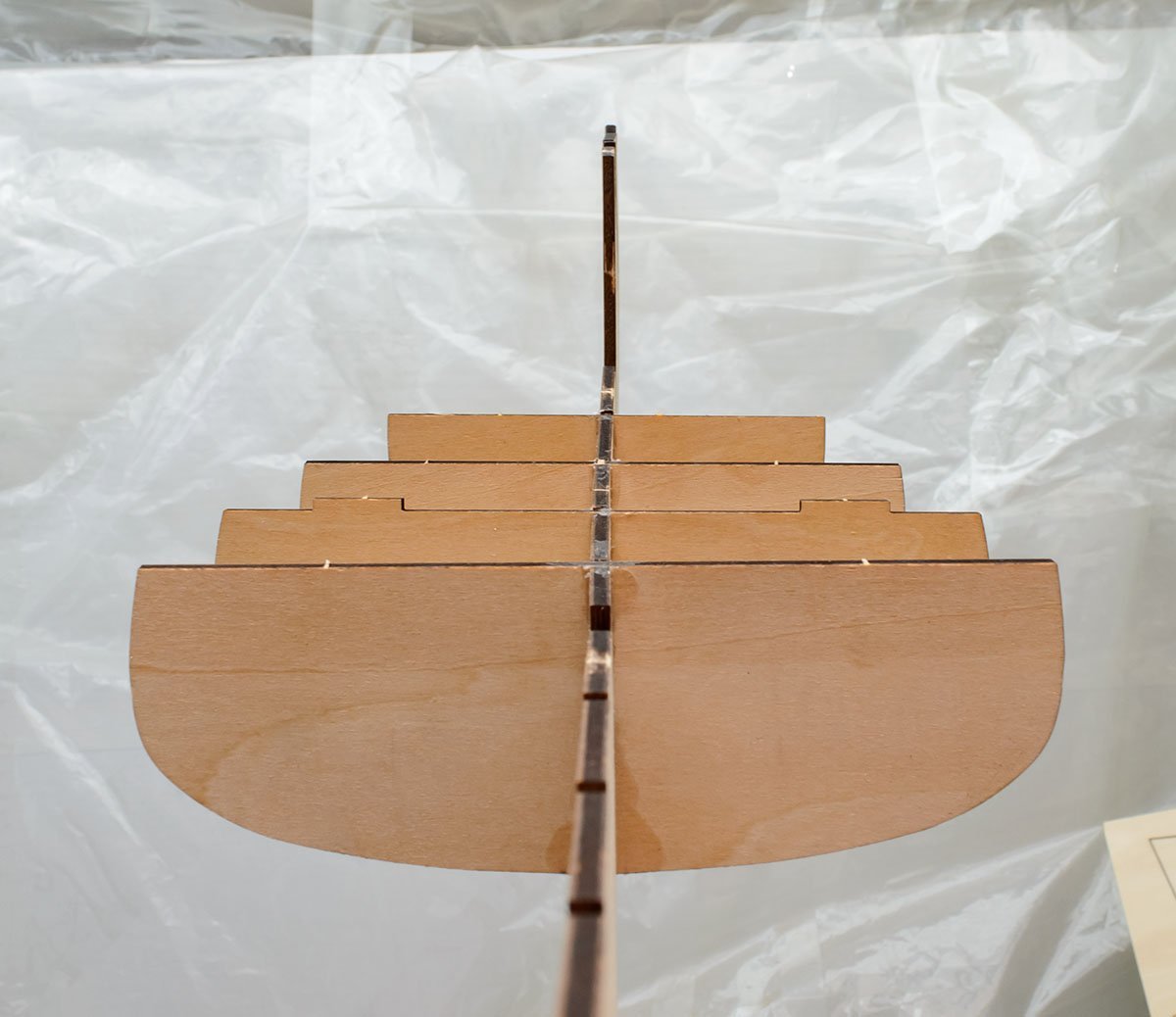
Let's start sanding before installing the first planks! This is a basic rule to sand at the end of each frame. The center of the frames shouldn't be shortened if they are installed correctly. Most frames are sanded diagonally. However, some frames, such as the widest frames (7 and 😎 are not sanded due to their position. It is called Φ frame. Also, in advanced kit, fore frames are numberd ,2,3... and aft frames are referred to as A, B, C,... As frames go from the center to the edge, the frames' size is usually smaller than before. Putting a ruler vertically will help determine the tiny angle differences. I don't use any special tools to sand frames. We really don't need to sand frames too much. You may worry about shaken frames. I reinforced frames with junk wooden blocks. When we use the junk wooden blocks for planking, there are several purposes. - Strengthening keel-frames-deck - Keeping distances of both frames equally : if you are a new builder, you can't do this unless you learn how to use an extremely dangerous table saw. 😬 - Replacing 1st planking : extremely useful for stern and stern post that have very fast curves. I used balsa wood. It is a versatile and handy wood that is easily cuttable. It is good to buy some balsa wood for your second build. The parts 19-20-21 do what balsa wooden blocks do. ( source : https://commons.wikimedia.org/wiki/File:Calabash_(Lagenaria_siceraria)_in_Seoul.jpg ) A sailing ship's hull isn't a calabash. Don't make any concave curves. Always make a fish type hull. If some frames are lower than nearby others, it means something is wrong. I check frames and balsa blocks frequently using strips. Don't twist or force the strip. The best planking line is not a Mobius band. There is a gap. I sanded a frame 3 more than optimal. I'll fill the gap. If you built several kits, you may have spare strips to patch the gap. If not, use junk wood like me. Just don't forget that a sailing ship isn't a calabash. If some planks are 'flat' due to three frames in order of having the same height, it may be bad or not. It depends on the situation. I'll show why the new Santa Maria kit has a weird 'flat' planking line at the head soon.

_in_Seoul.jpg.6ca7b39efc623ec91eb203564f90a0b7.jpg)
- 77 replies
-
- 1
-
-
- Santa Maria
- Artesania Latina
- (and 1 more)
-
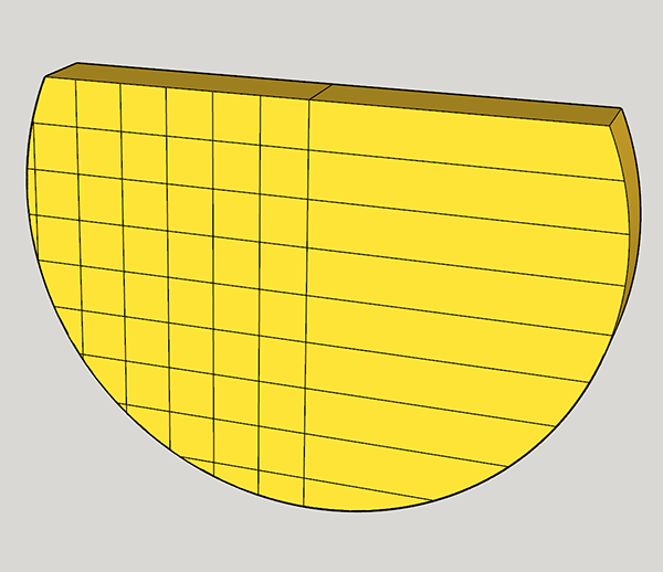
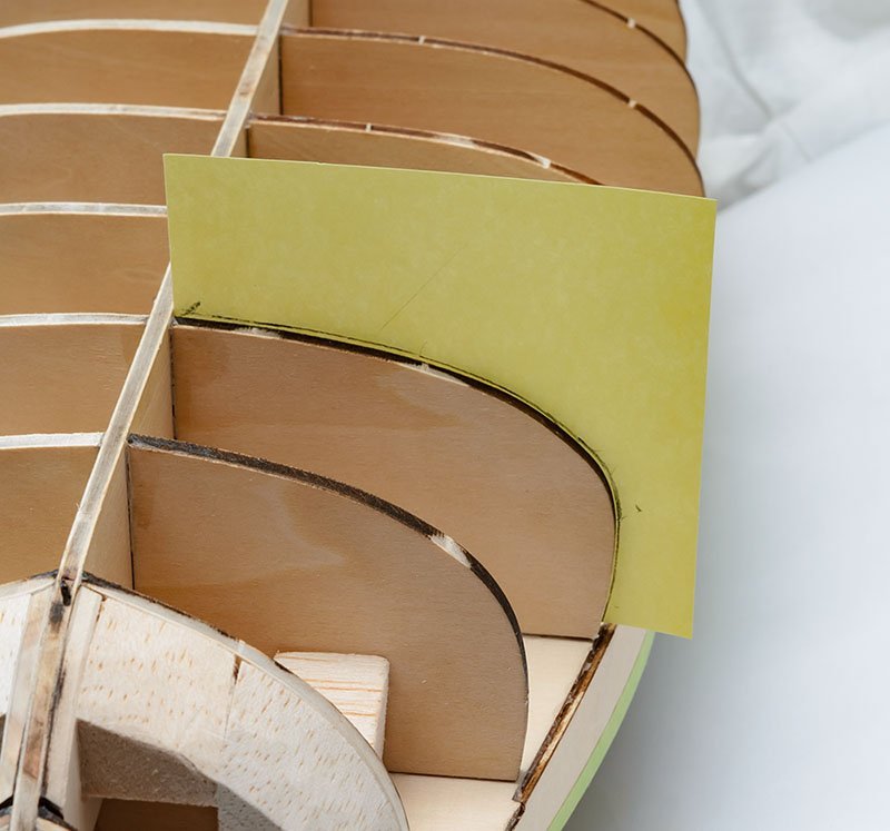
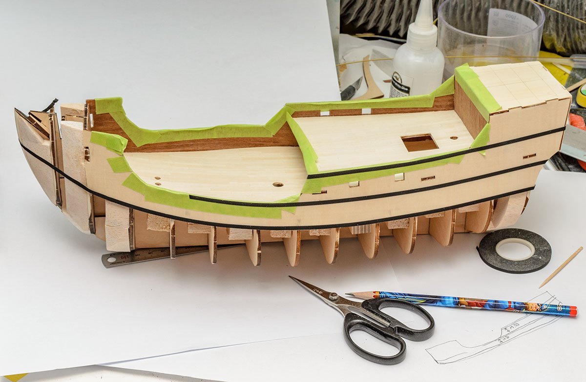
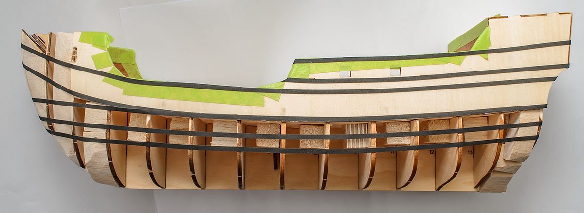
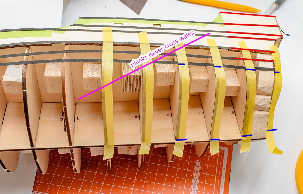
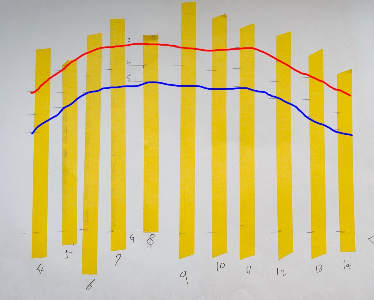
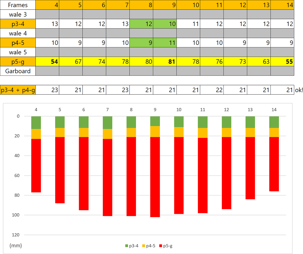
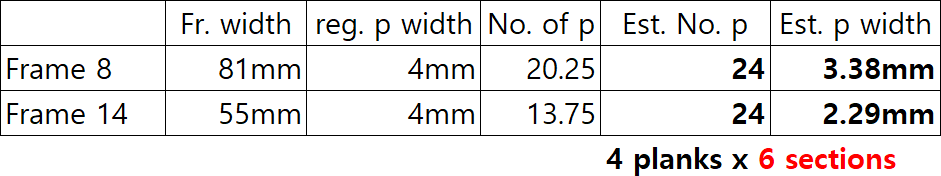
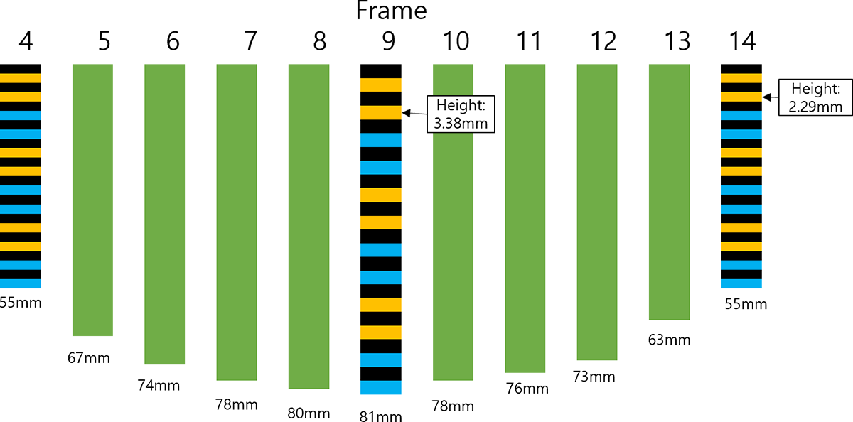
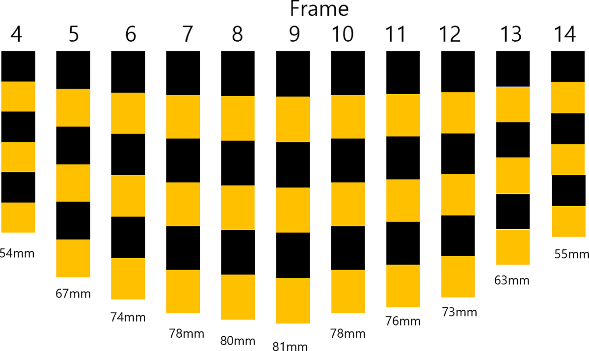
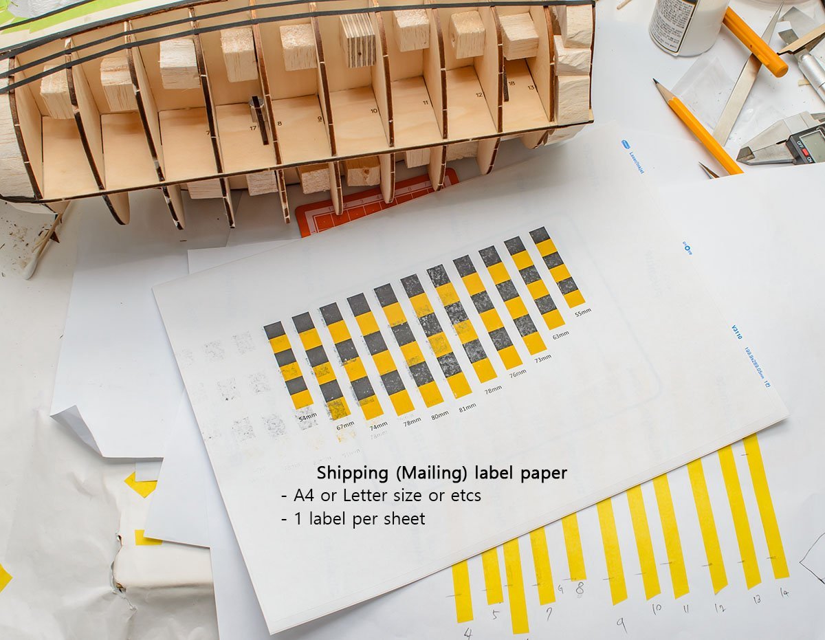
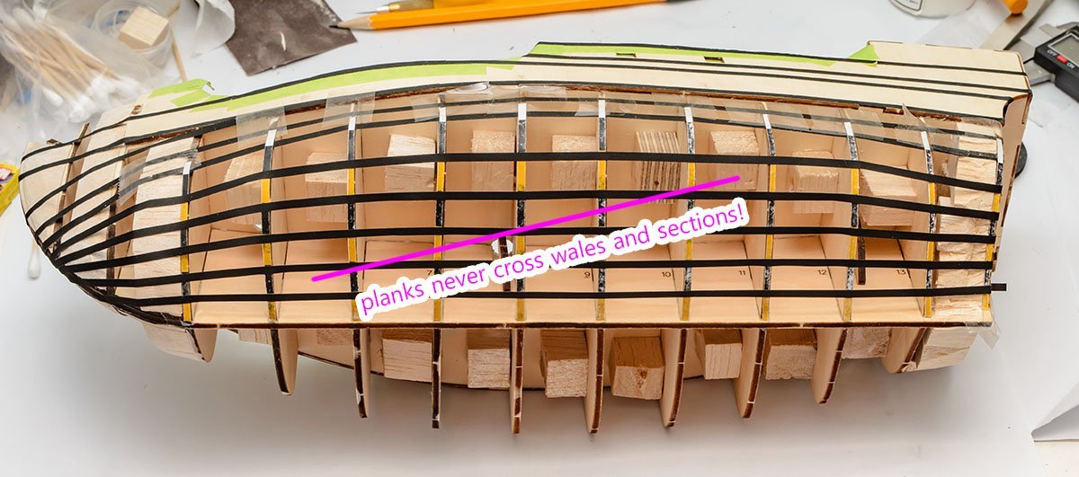
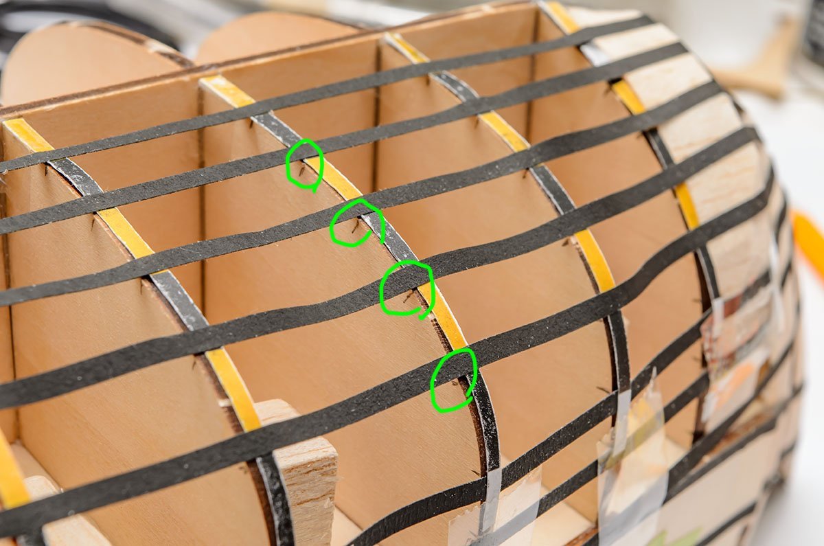
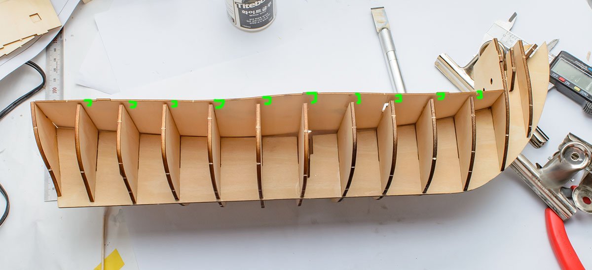
I drew all the wales using 3mm line tape. It helps how the planks will run. Let's find the rest of the plank lines. I won't follow the AL manual's elementary level planking lines. I'll make planking lines that are not cut in the middle. It includes both up and down. To get a clear and unstressed planking line, I have to sand frames well before I install planking. I measured the length of each frame using masking tape. (Blue ticks) OK, let's open Microsoft Excel. 😉 There are some minor errors when I measured masking tapes with a ruler, but it seems negotiable. (< 2mm) The plank section between wale 5 and garboard (p5-g, red colored) is what I wanted. I'll divide the wide section into narrower parts to hold the planking lines. The widest frame 8 is 81mm and the narrowest frame 14 or 4 is 55mm. The kit will use 4mm wide walnut strip, so I need at least 21 planking lines to feel all the hull. Don't forget that I measured frames only. The hull will bulk up like a balloon after I finish the first planking, and the frame width will increase as well. Including the margin, I decided the total number of planking lines under wales is 24, and width of planking will be between 3.4mm and 2.3mm. (It's not recommended to cut a strip under 1/3 of width.) Moreover, I bound 24 planks into 6 sections. Normally, each section includes 4 or 5 planks depending on the planking pattern. As a result, each frame's width of section should be this. Let's open Powerpoint. 😆 Well... I don't know how to use the radial line sheet. The Microsoft Powerpoint can handle up to 0.01mm, which is sufficient in my opinion. This diagram is not necessary for you. I'm just showing how planks will run. I drew squares without outlines to get the exact size. I made 'section' strips. Each section includes 4 planks. I printed it on mailing sticker paper, and cut the lines. You'll need to resize the printable area smaller than usual. Otherwise, Powerpoint will resize the result. Make paper margins wider than 3.5 cm. I forgot to remove the scorch mark when the plywood was cut by a laser cutting machine. The soot makes dirty dust and a glossy surface that is non-adhesive. I applied line tapes again. Isn't it clearer than before? It seems the planking section lines are legitimate and flowing. I left markings on the frames. They help shape the hull. This procedure may seem too complex and ridiculous. I'm not an expert modeller, so I have to spend more time to get the same result.

- 77 replies
-
- 1
-
-
- Santa Maria
- Artesania Latina
- (and 1 more)
-
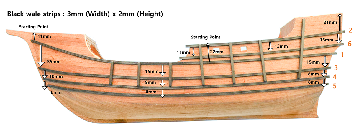
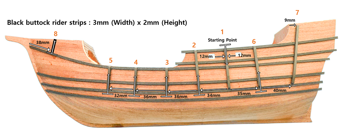
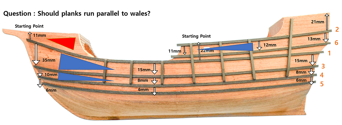
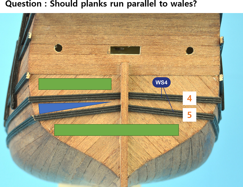
Long time no see, DanB. I'll run again as I finished a difficult part. Hello, Moobug. You're right. I'm using the clamps All the time, and planning to buy more clamps. 🤪 Also, thanks for leaving your great build log. It helped me a lot when I encountered a current issue that the wall panels didn't match bottom deck and fore frames. Sorry for late update. I'm looking for easy method to explain planking. I'm using a slightly different approach from a manual, and I'm almost sure what are my method's benefits and disadvantages. I'll continue regular build log as I finish all the first planking work. By the way, I found an interesting part from the new kit's manual. These are quick cheat sheet from manual pages 54~59. The new Santa Maria kit has super detailed direction of wales and buttock rider strips. The 30 years old kit didn't explain that, and nobody probably has ever seen this numbers before. You can see the buttocks are neither vertical to waterline nor parallel to themselves. It is quite odd and I've never seen before in previous build logs. In addition, this new pattern isn't same as illustrations in the Anatomy of the ships book. I'm curious about the reason of the positioning and specific numbers, but I would like to focus on planking related topic only for now. I thought the wale lines run with planks, but some wales such as the 1st wale makes fast curve which isn't allowed for planking. In general, planks are getting narrower as they run from center to fore and apt. Therefore, the blue triangles imply the width between the wales are wrong. Moreover, if wale runs with planks, should I change the planking pattern at transom? I read some topics regarding wale and planking. I found that the wale lines are important to determine running place of planking strips according to Patrick's PDF document. On the contrary, some buttocks and rare wales can be installed over planking. Go to the 4:10. This is a 2018 Nao Santa Maria replica. It uses horizontal planking at transom, and the 1st wale looks like be installed over underlayer planks. In addition, the rear of the 2018 Nao is not a box spae, but a streamlined shape like modern ships. It should be interesting topic to study the difference among an old AL kit, 2018 Nao replica, and the new AL kit, but I would like to re-focus on current benchwork. I have to finish planking ASAP. 😭 In conclusion, I'll follow the most of wale lines as base lines of 2nd planking strips. However, some planking parts such as fore side of 1st wale and transom side won't run together like in the manual. If you have any advice about relation between wale and planking, please feel free to leave a reply. I just mixed various methods, and I would like to hear any idea to make model better. I think the hardest part is done. The ship is almost symmetrical, and looking quite stable. I'll finish rest of planking work soon.

- 77 replies
-
- 1
-
-
- Santa Maria
- Artesania Latina
- (and 1 more)
-
Detail sander from an electric toothbrush
modeller_masa replied to grsjax's topic in Modeling tools and Workshop Equipment
I'm not sure I've introduced this tool here before... https://www.1999.co.jp/eng/10605990 This is more like professional polisher, and I guarantee that it pretty works well although limited usage... There are some cheaper copy polisher on the ebay from $40. If you purchase the chinese version, you can change speed of the sander using a variable voltage controller. -
Looking for a good "starter" pin vise set
modeller_masa replied to Capella's topic in Modeling tools and Workshop Equipment
The drill bits for PCB circuit board are the best accurate drills you can get, but its length is short. Even cheapest $1.00 10 bits set is fine. You can find wide range from 0.10, 0.15, 0.20mm to 2.80, 2.90, 3.00mm. I have all 10 of them. Buy the best collet when you need better one. Never buy cheap collet. I heard that a collet from Swiss is the best for jewelry, but it depends on nation and area. -
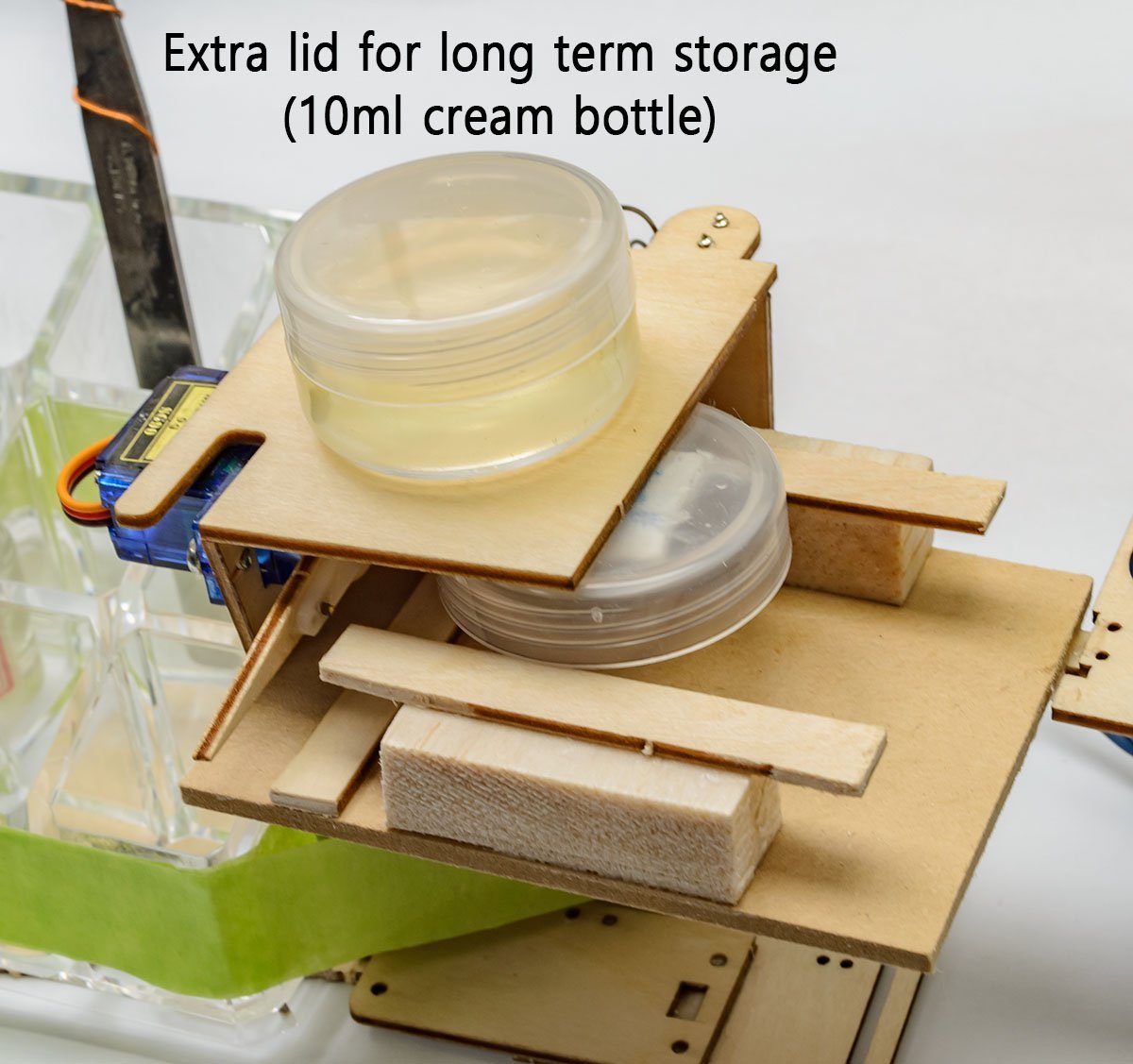
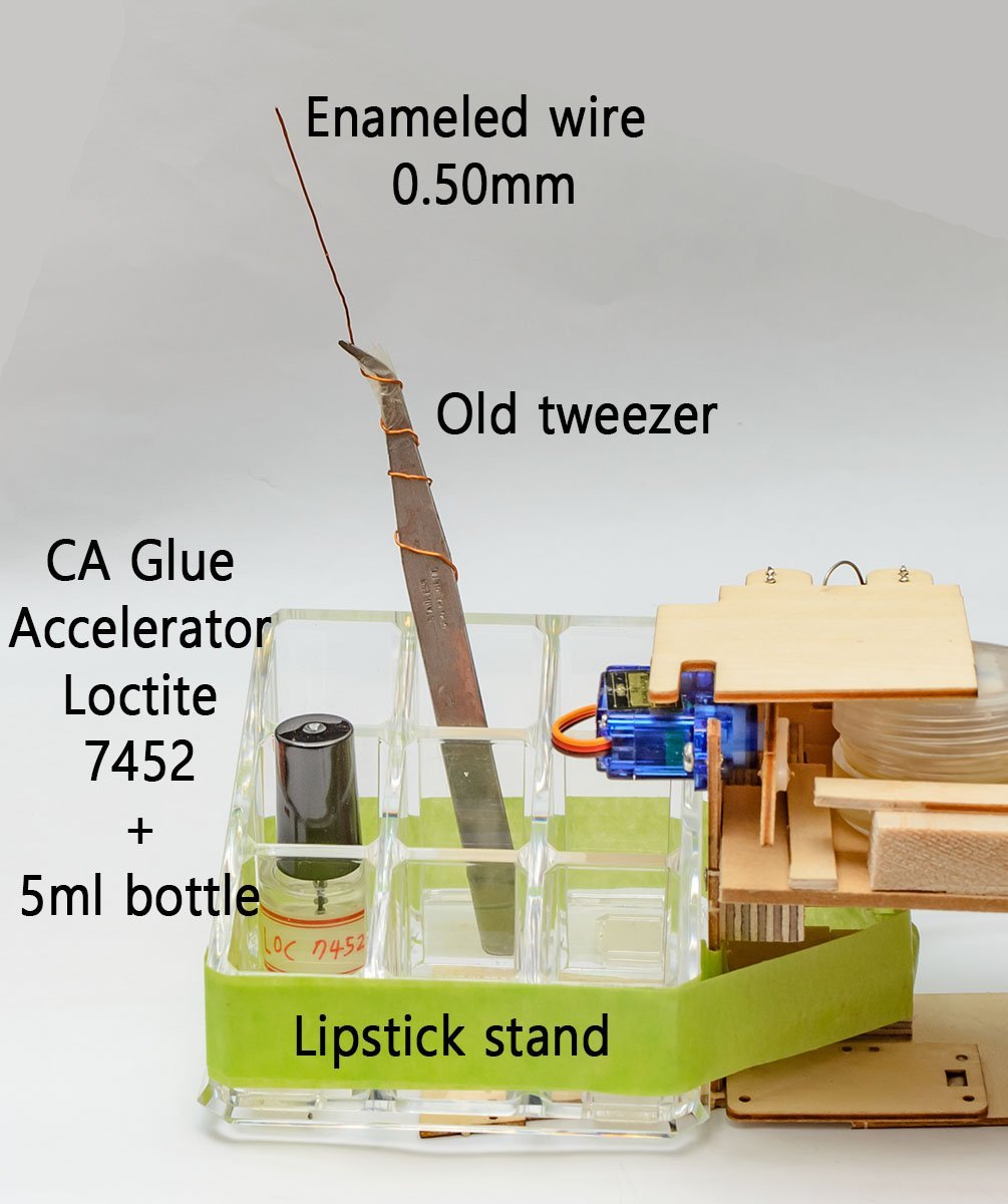
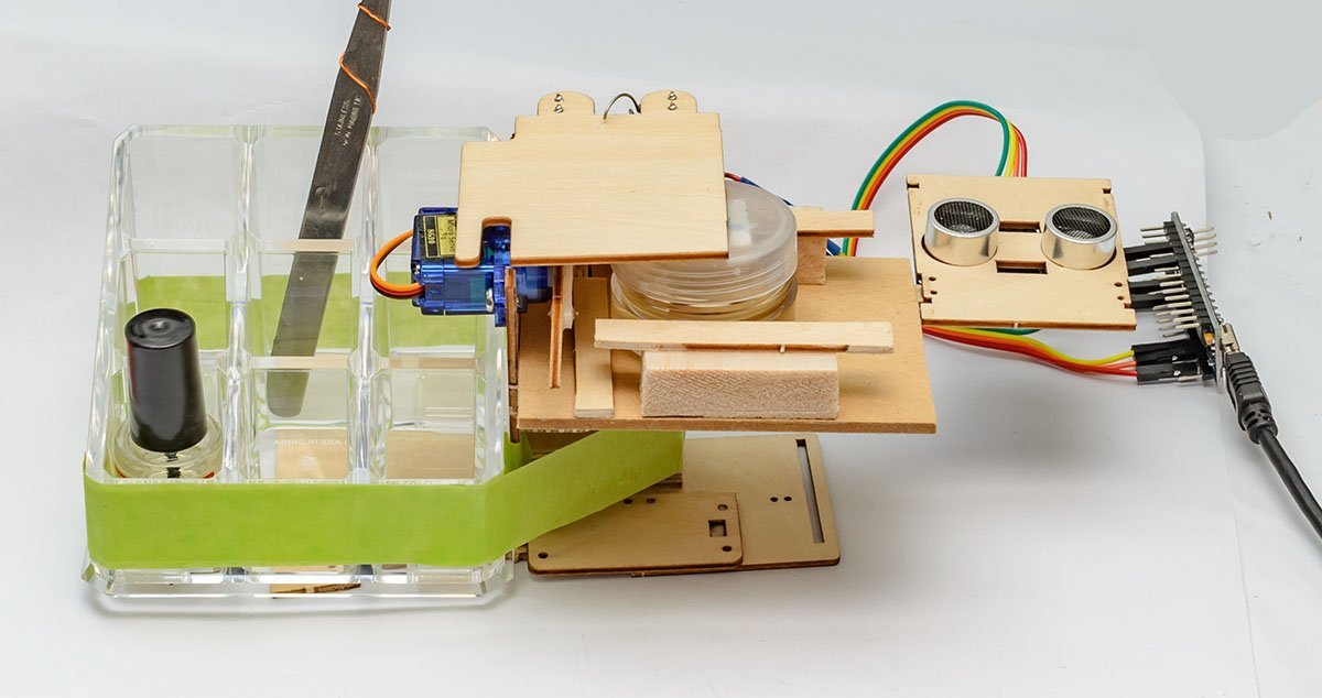
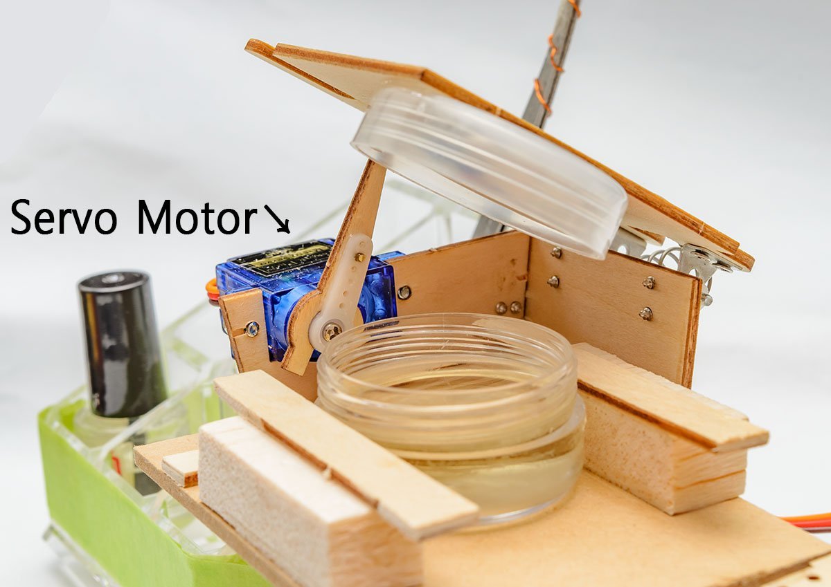
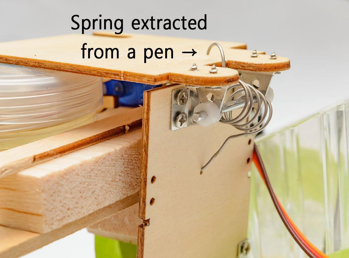
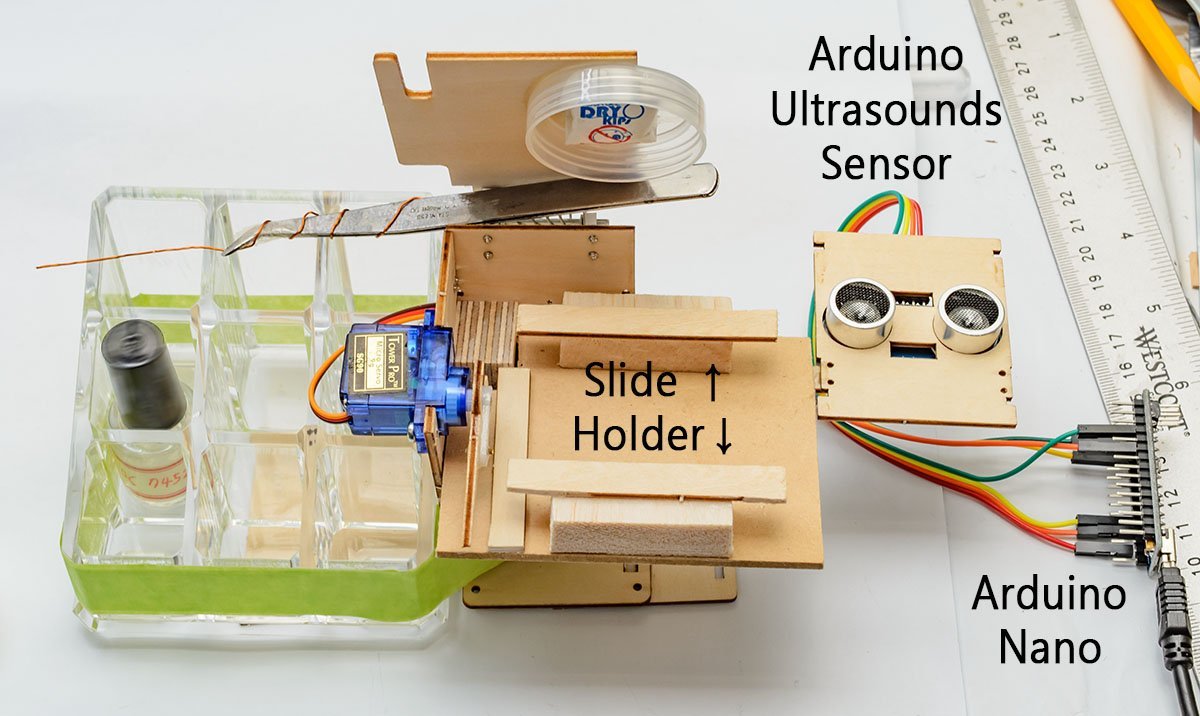
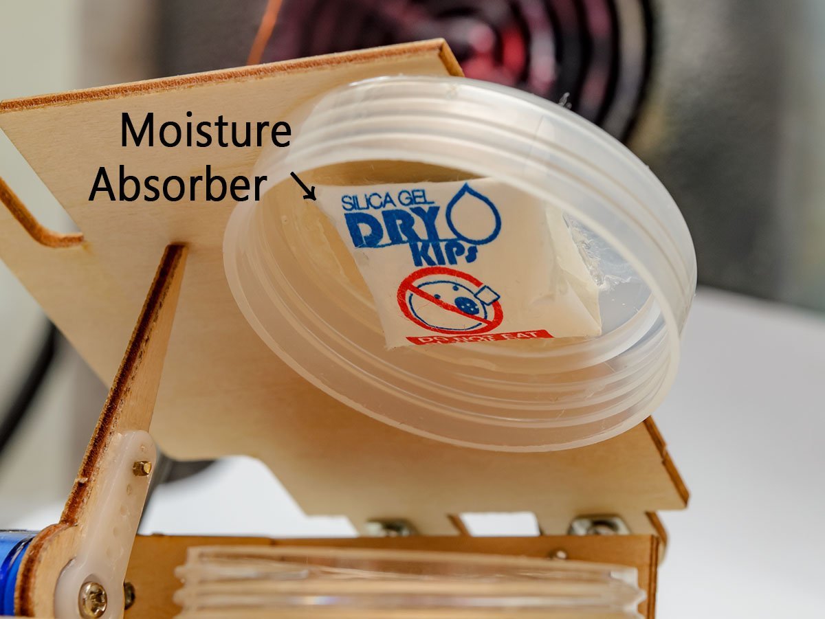
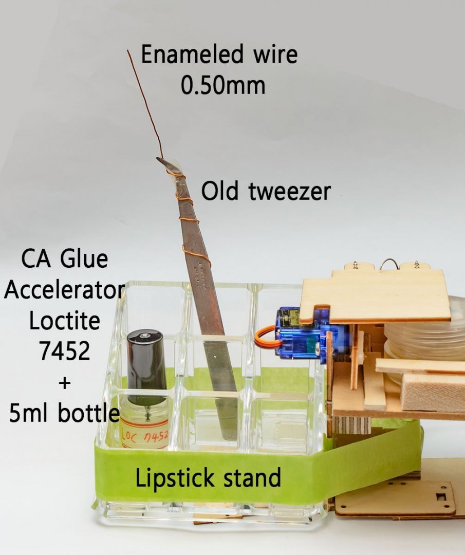
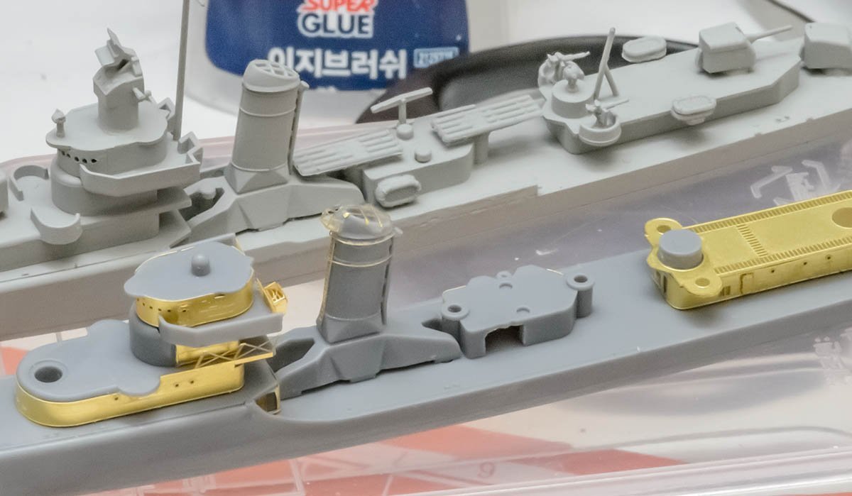
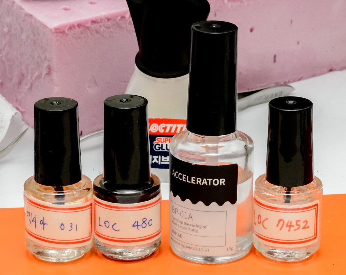
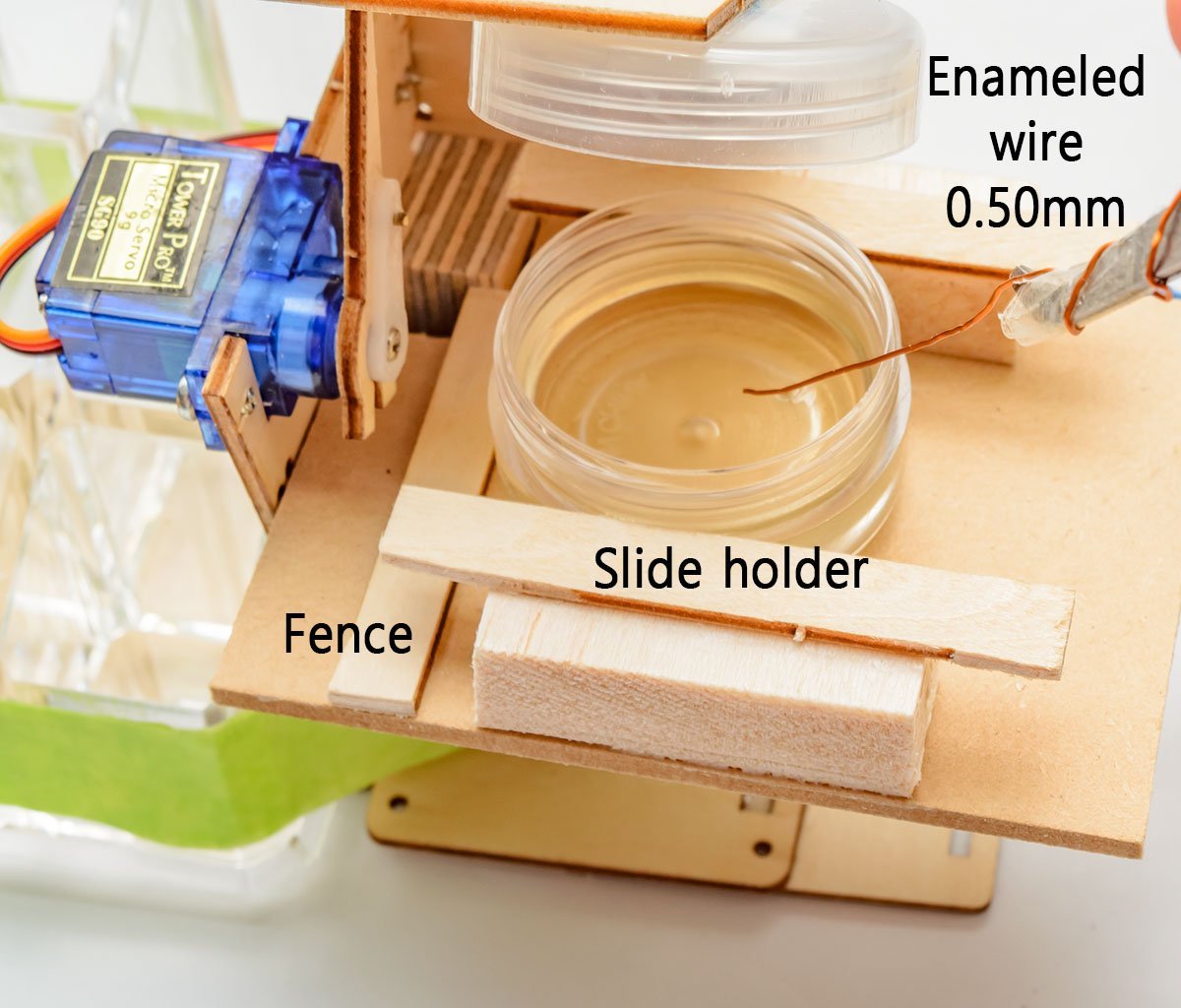
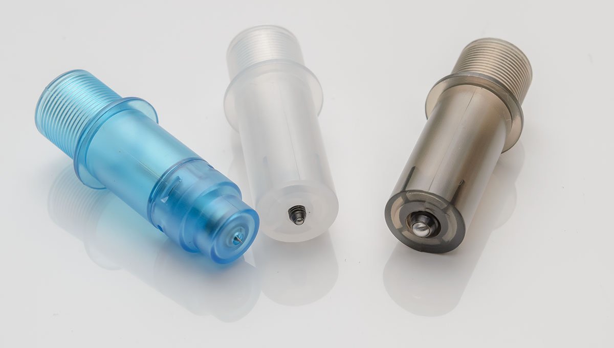
Hello, I made a small tool for small scale ship models such as 1/350 and 1/700 scale with photo etched parts. It is a CA glue station that automatically opens and closes the lid. When I built several 1/700 ships, I faced some issues regarding CA glues. They are easily degenerated by moisure in the air. Also, openning and closing a lid of bottle every time is annoying. In addition, the glue bottles are not convenience. The bottles are easy to spill, and narrow neck interrupts the lid's brush. Ultimately, I had to dump huge amount of degenerated sticky CA glue with the bottle. I bought some small bottles with brush to overcome the demerits, but it helped me a little. I dream of fully automated lid CA glue bottle. I dream of CA glue bottle protected from moisture. I dream of wider bottle neck for comfortable work. I got an idea from educational sample project, 'Smart trash bin' for Arduino curcuit board. I purchased relatively cheaper 'smart trash bin set', and modified the parts a little bit. I used a pen spring to give a tension to a lid. The Arduino is a very common programmable board that children can play with it. I downloaded the source code from here and modified timing to 10 seconds. https://github.com/daveqin/Smart-Trash-Can-Project I also made slide holder for attaching and dettaching CA glue bottle flawlessly. The mechanism should hold the bottle tightly against shock from the closing lid. I usually use an enameled wire for 1/700 photo etched parts. It is cheap and I can minimize an amount of CA glue. This small moisture absorber will prevent moisture and extend life of CA glue in a bottle. When I go to a bed or finish a project, I eject a bottle from slide holder and close it securely for long period storage. These are my tools for photo etched parts. I hope my new tool reduces stress caused by CA glue. Thanks for watching.

-
- 6
-
-
-

-
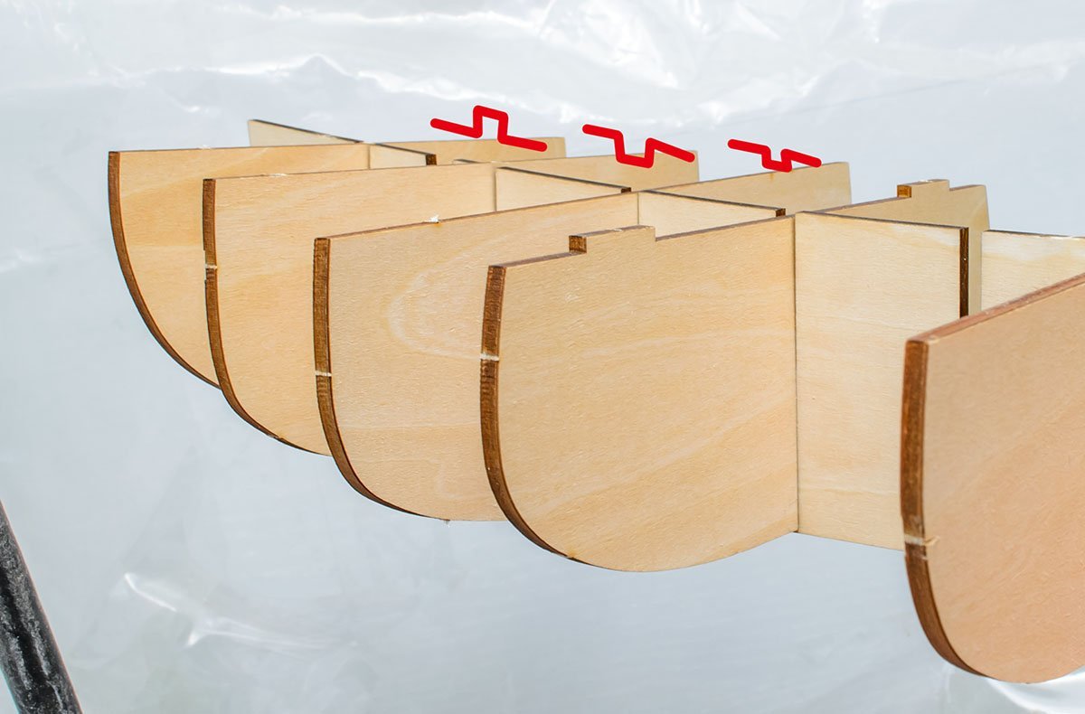
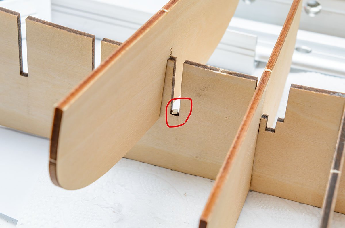
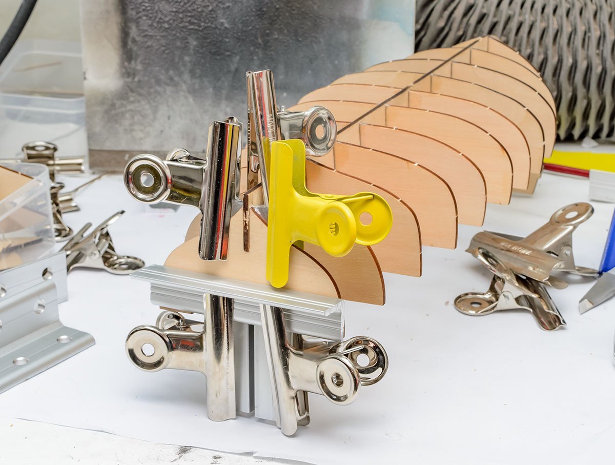
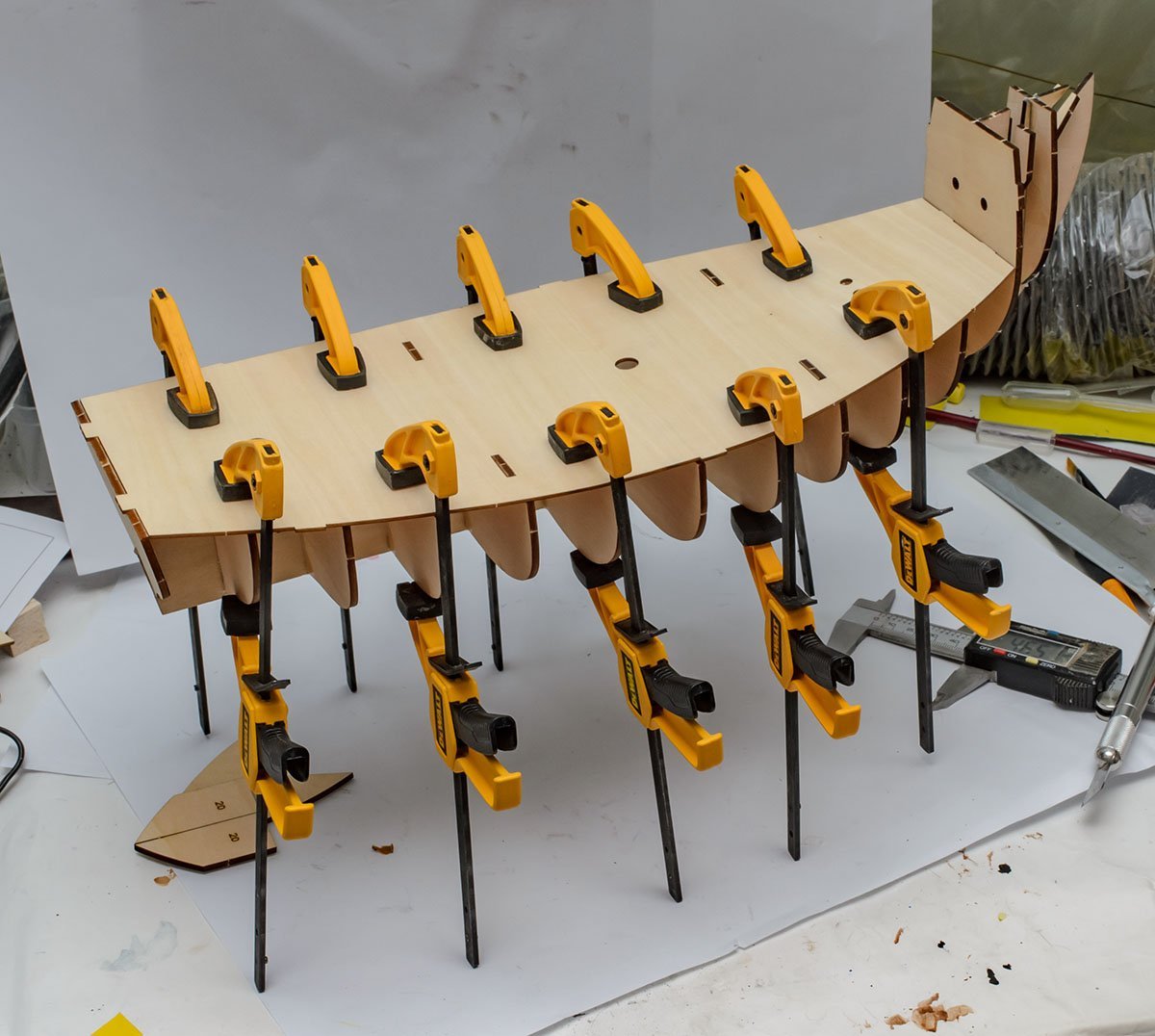
Thanks Dave, I'll keep build log simple. You finished the NRG HHP kit. It is excellent choice. My last wooden ship project was also NRG HHP kit. Some frames are higher or lower than the other frames. They may be how was made, but it can be an cutting mistake in most case. It happens frequently due to many reasons such as machine error, changing materials, etcs. After I checked manual and tested other nearby interfering parts, I decided to fix them. Frame 9 and 10 is slightly lower than the others, so I let a small piece of wood. Frame 11 is higher, so I cut inside a little bit using 1.0mm electric drill. I set the frames to match the upper deck = No. 22 part. However, one frame was made to be higher than others. It is the last frame, 14. I didn't check it at manual. I lowered the frame 14, and found that the 22 deck didn't fit. 😱 I removed the 14 frame with water soaked cotton swab, raised level, and reassembled it. The next step is adding mast holders. They are hidden parts under decks and I can't calibrate for now, so I applied only small amount of glue. I'll align them later. You can see some frames are still twisted. I did aligning work pretty well, and it is natural. The reason is keel. Wood is not reliable material comparavely, so there is no way to make such long keel flat permanently. I'll correct the error by structual method. Some builders make holes and penetrate wood rod. This is not perfect, but very simple and effective way. However, first builders who usually don't have drilling machine can't do that. Filling wood blocks or wood rod is very traditional and basic way. Unfortunately, this is also not recommanded for new builder because you may not have deadly dangerous table saw machines. We need exactly same length of two wood blocks. The accuracy should be reached 0.01mm. Otherwise, the hull will be bent by the aligning blocks! It is super difficult for human hand, and only machines such as table saw make same result flawlessly. Table saw for modelling work is a bit expensive and requires several hours of safety education! Luckily, Artesania's new Santa Maria kit added gimick that aligns keel effectively. The red holes hold deck and frames, so it makes exact symmetrical port and starboard side. Thanks Artesania! There are still floating frames (green). They may be an issue, but negotiable. Forget them if you're first builder. Don't underestimate the previous aligning work. This gimick doesn't hold keel, frames, and deck at once. If you follow the AL manual or bond frames with 22 deck part directly, you may face more chance of asymmetry error. Different size of port and starboard side cause uncountable issues. You will see the gaps between frames and 22 deck. The gaps aren't tolerable. Check the manual page 20. This kit is designed by complex 3D CAD, and curved 23, and 24 parts are designed to fit 'bowl shaped' 22 deck. I used many number of quick release clamp for woodworing. Probably this step is the most like woodworking among all wooden model ship building progress. In other words, you may not need to use these 'big' clamps later. If you think cost is burdensome, I would recommand to use rubber band or velcroed band. Seems ok to go. Ouch, I found that both 23 and 24 don't fit at here. (Frame 3) It implies remaining aligning work, but I won't diassemble frames and rework them. 😭 I checked nearby interfering parts, and concluded that it is negotiable error. I'll enlarge the hole slightly. The next step is break corner. I put them on the red lines (keel). If the space is too narrow, sand inside (green) only. I already decided 50% of hull shape. In the next time, I'll determine 40% of hull shape. What I'm saying is that the next step is the most important step when we make wooden model ship. Attaching planking is a skill, but planning planking makes final shape of hull and determines entire ship. Polishing planks changes appearance a little bit, but it changes less than 10%. Even expert modellers say the hull construction and planning planking is the most difficult... and exciting part. Here is a cheat sheet. 😎 I'll apply the knowhow what I've learned from Toni Levine's tutorial.


- 77 replies
-
- 3
-
-
- Santa Maria
- Artesania Latina
- (and 1 more)
-
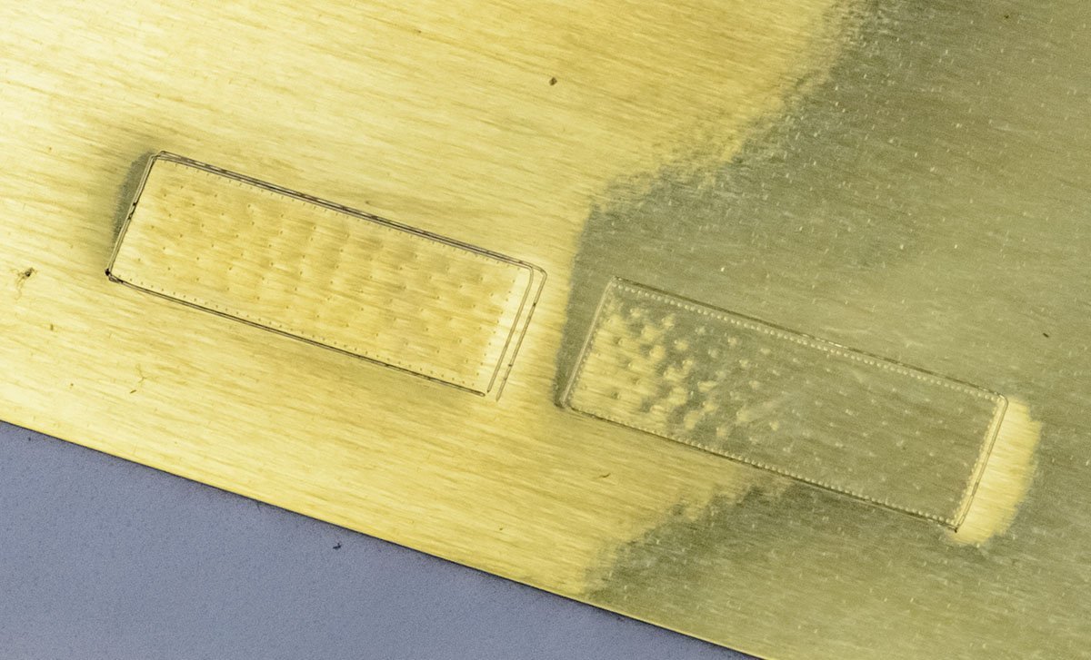
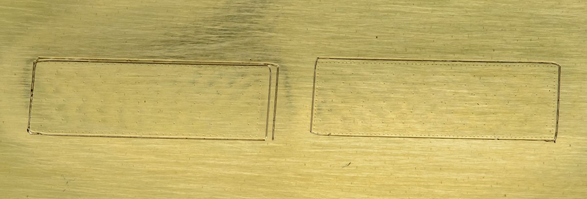
I found that the newest version of the Silhouette Studio 4.4.920 doesn't support well the old Curio machine. I tried an integrated calibration function, but it didn't work due to a software bug. I deleted the newest version, and installed the latest version of 3.x Silhouette Studio. Finally everything works smoothly. 😎 I ran calibration successfully, and even I didn't need to run calibration because the 3.x software corrected distance errors well. 🤪 Although the old version isn't convenience, 3.x version is only stable option for Curio for now... Here is a test copper sheathing just for fun. The size is 18.2 x 6.2mm. I used 0.005" = 0.128mm brass sheet. That's all. I go back to workbench. See you again soon. 😀
-
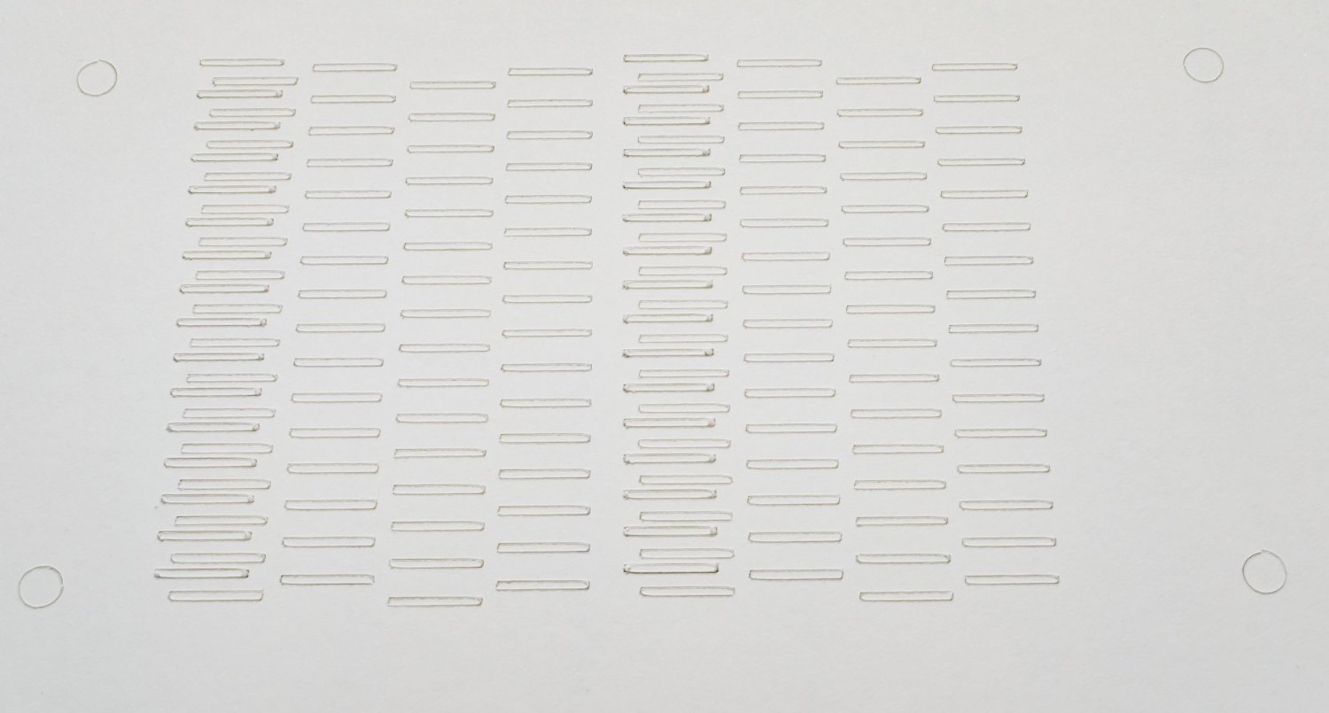
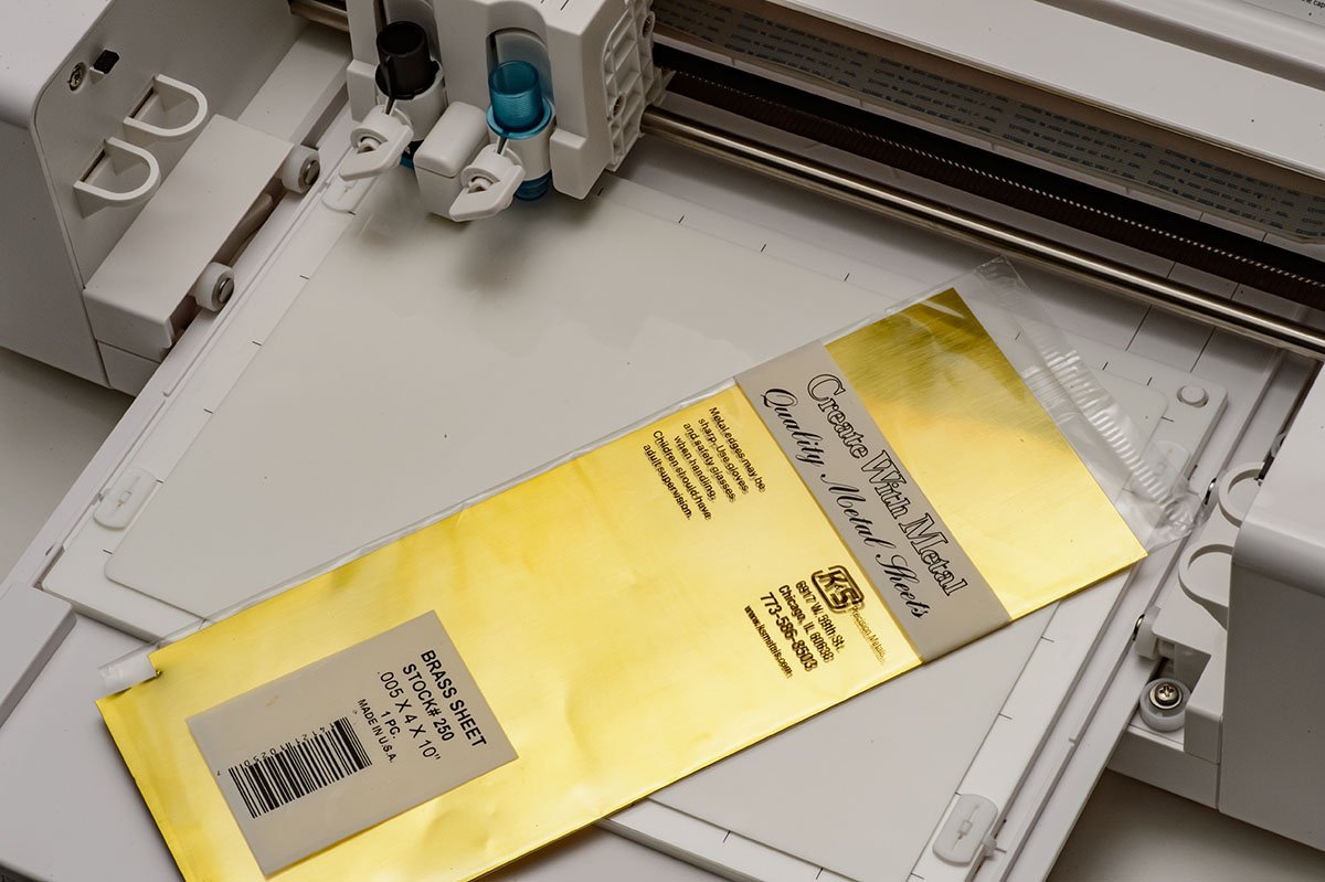
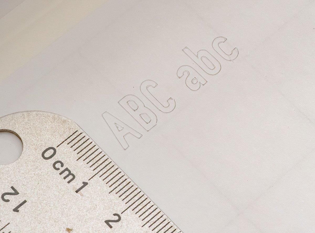
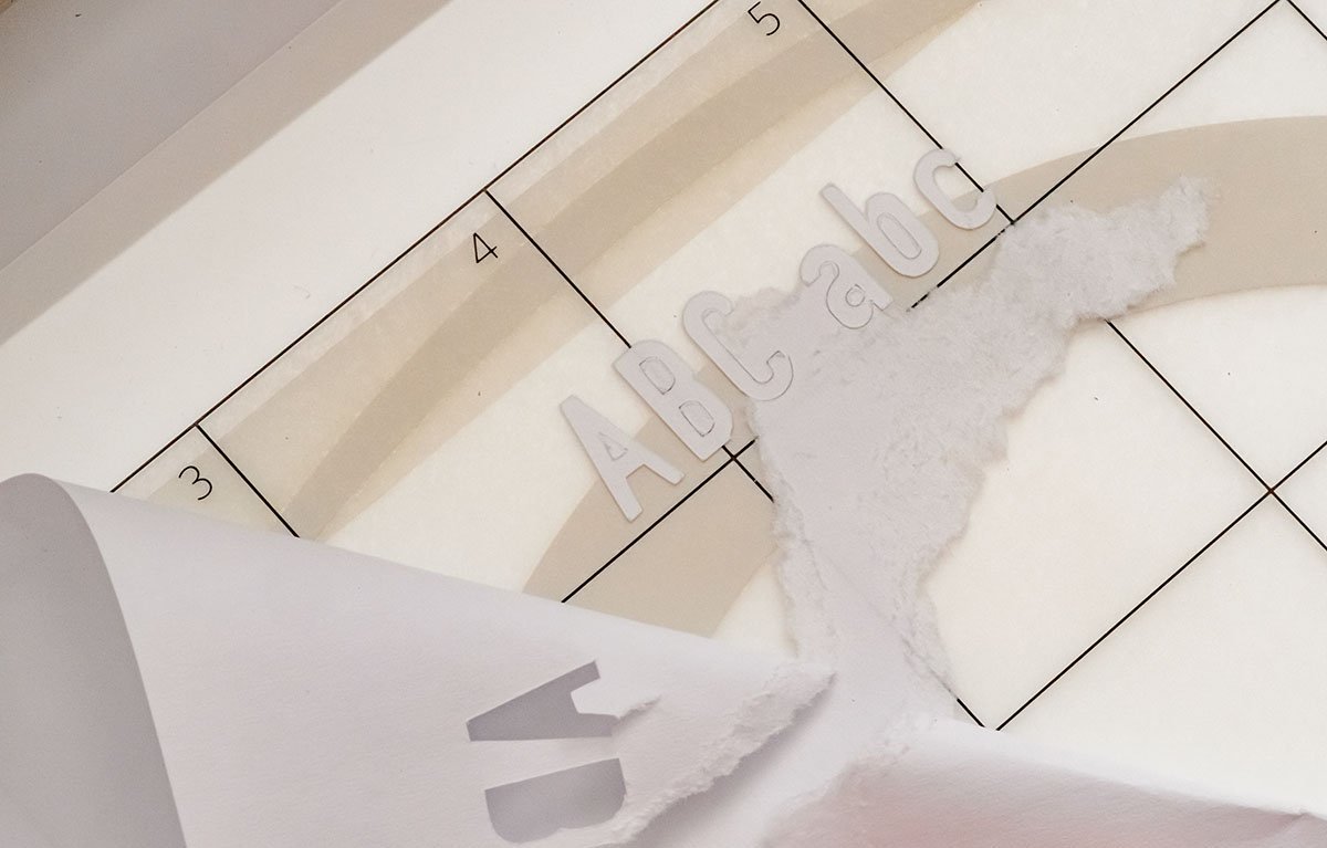
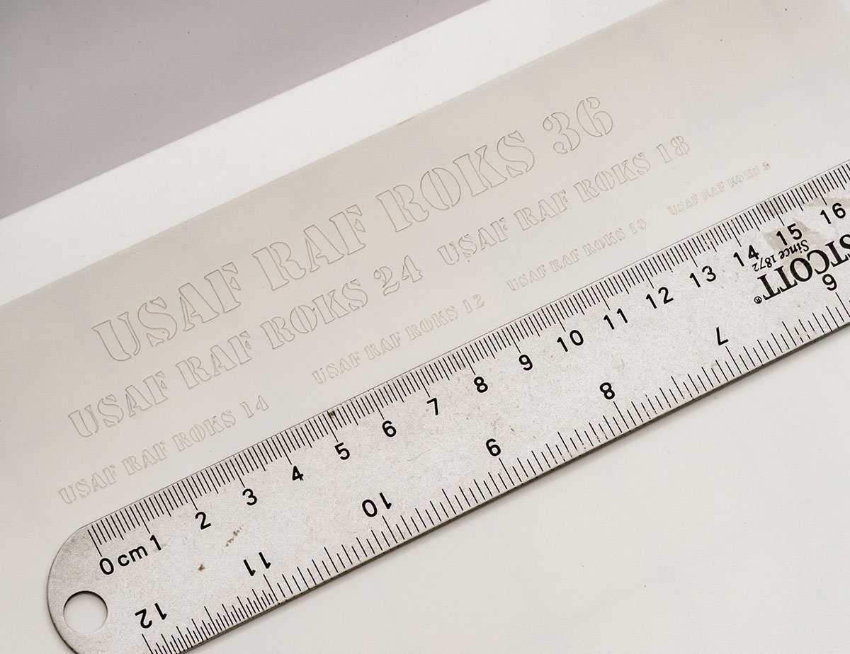
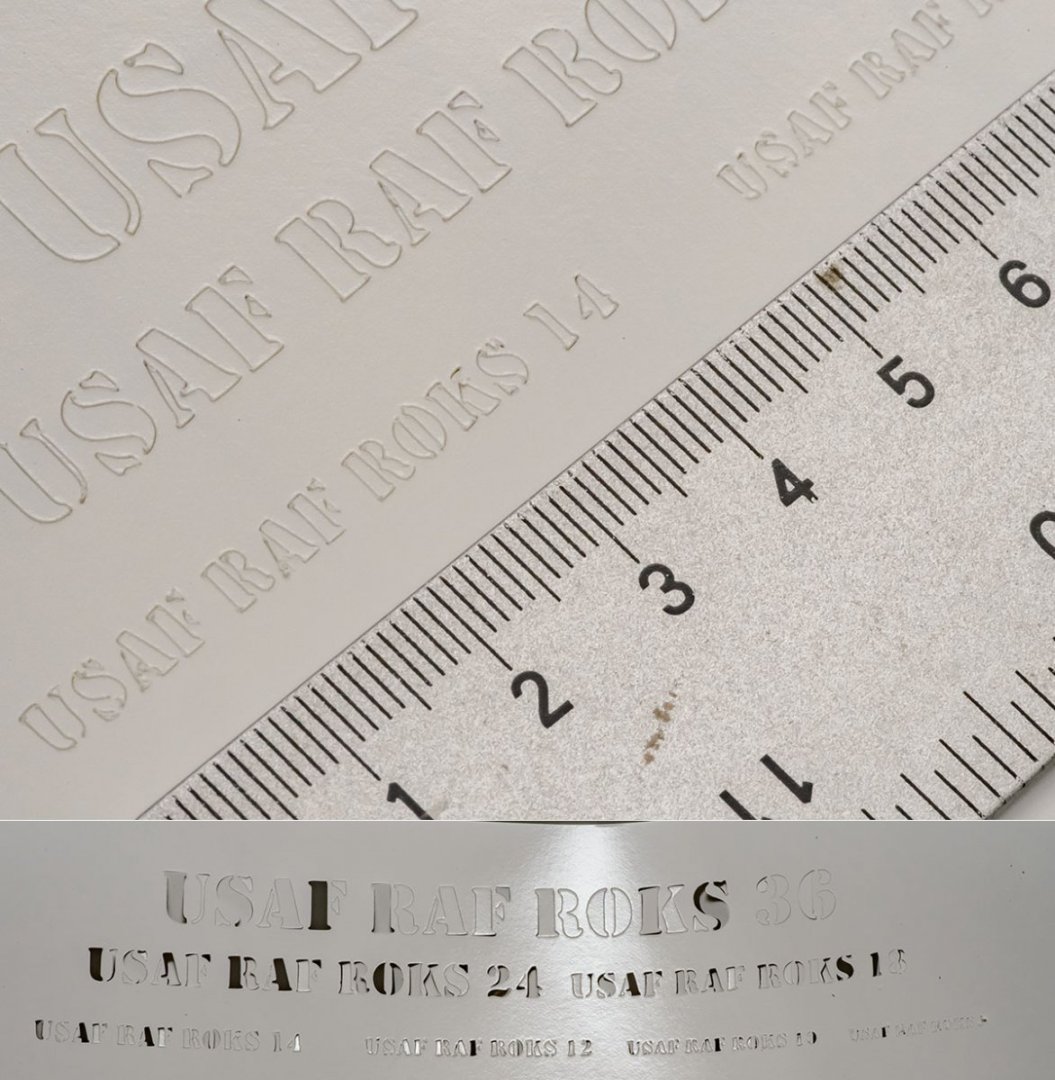
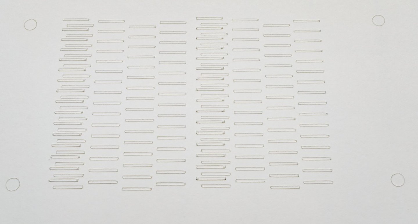
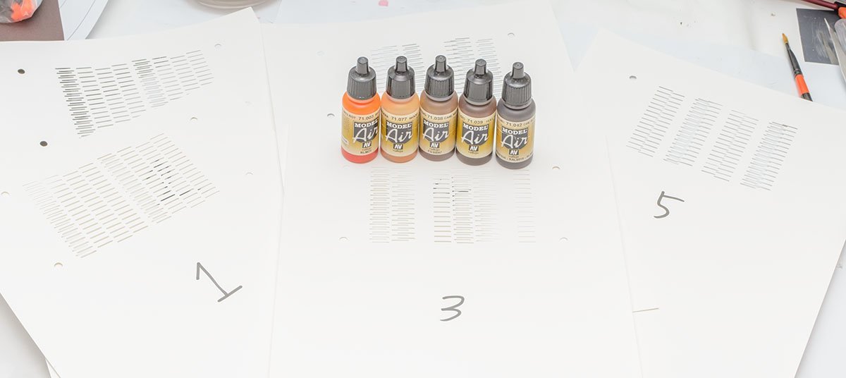
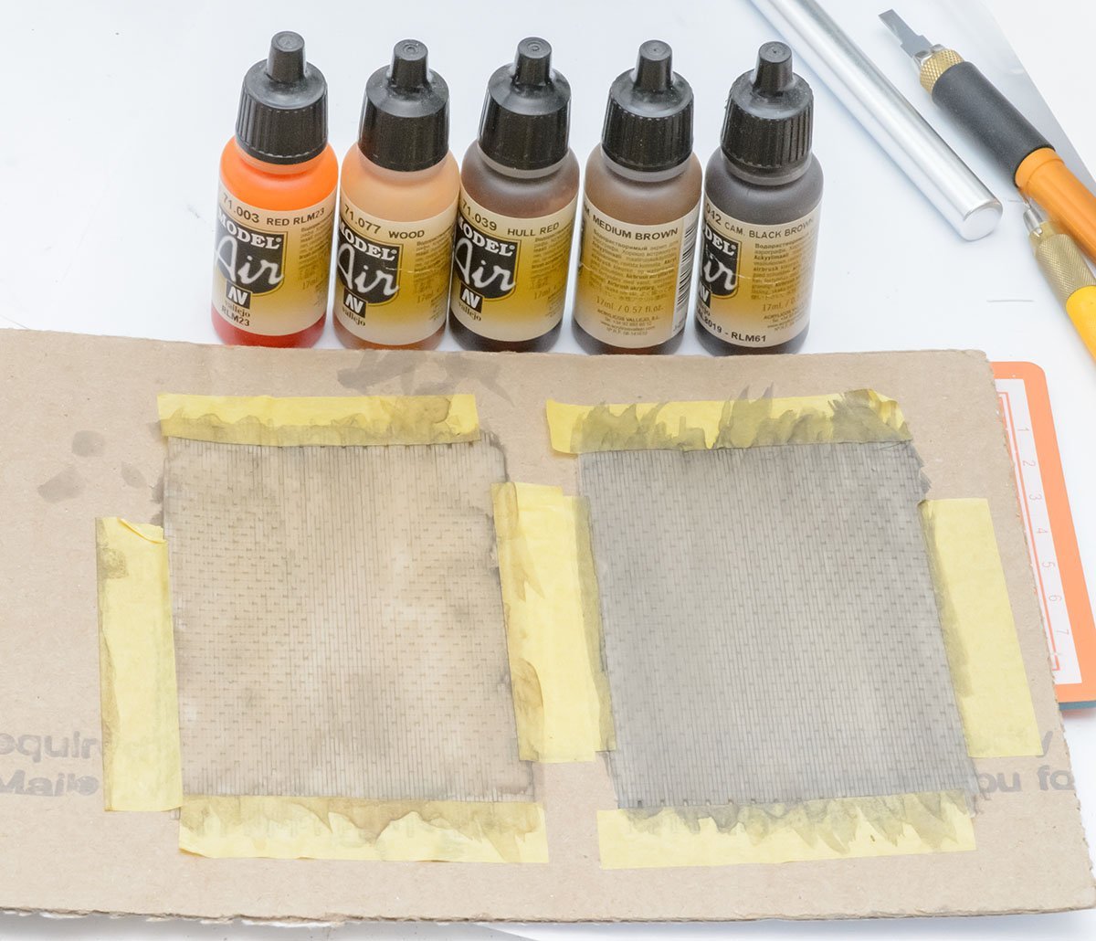
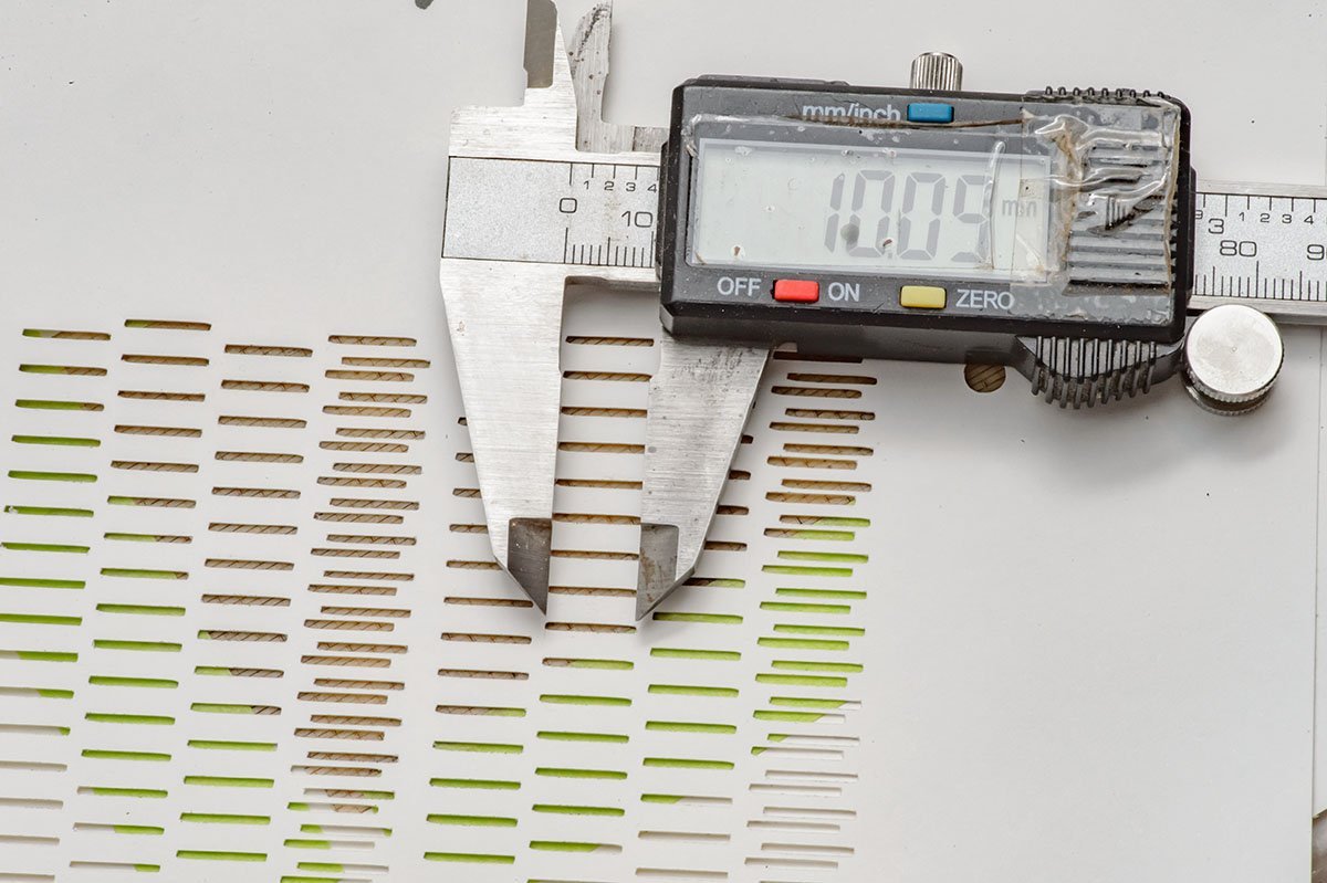
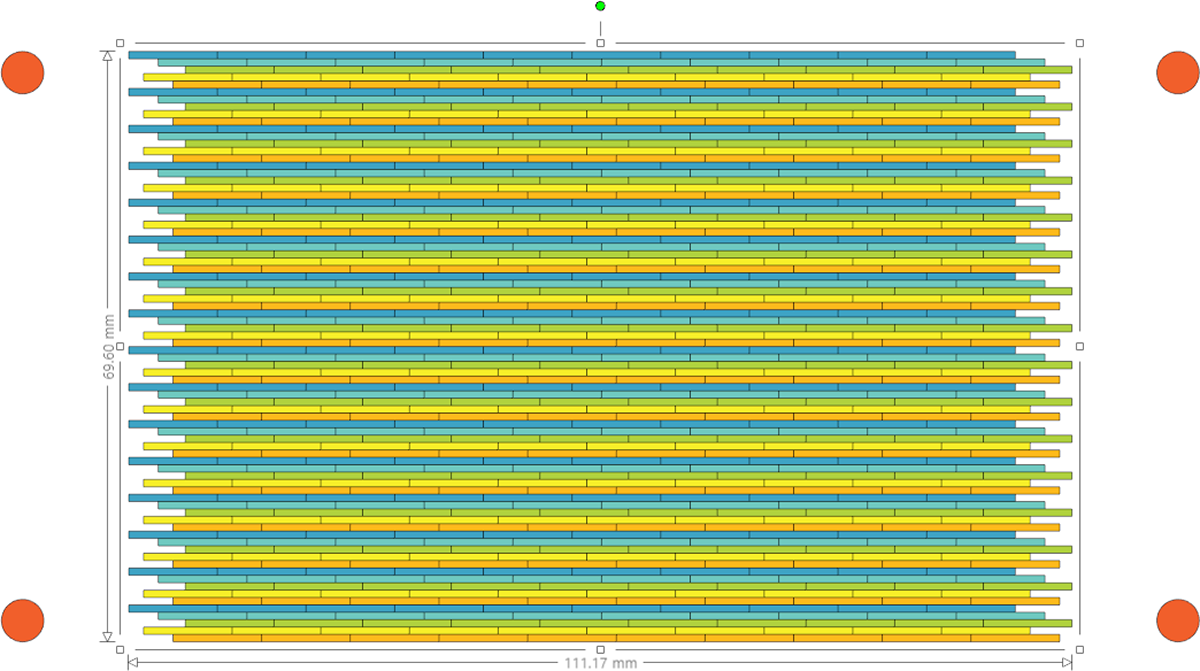
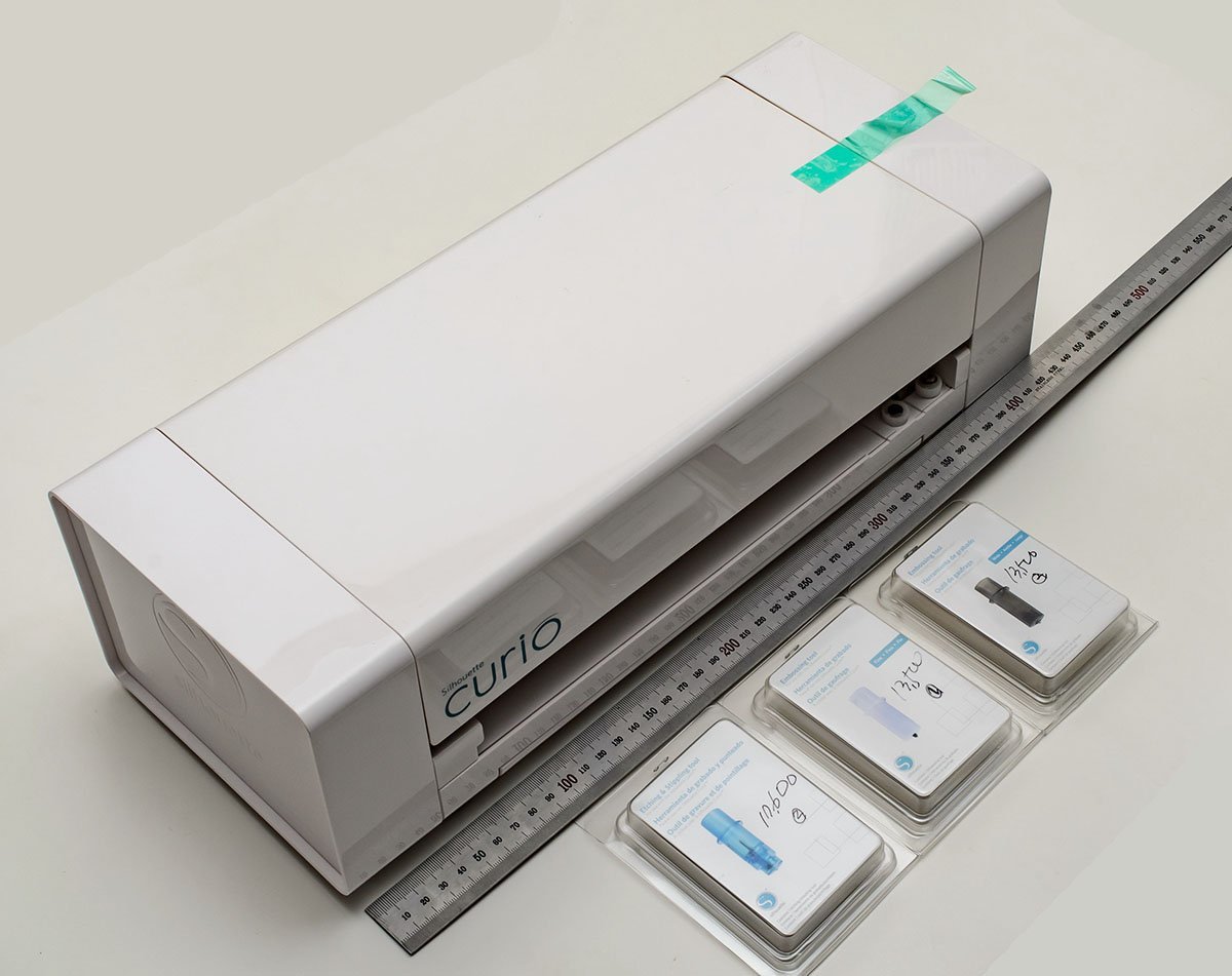
I bought a Silhouette Curio. This machine can cut, emboss, and etch paper, brass, and stainless panel up to 6mm unlike brother paper cutting only models. There are broader options for Curio. Center and right bits are embossing bit for paper such as christmas card, and left bit can make scratch or holes on paper or brass panel. I'll use it to make copper shield. The resolution is up to 1200 DPI. Here is sample plain paper cut test. This machine uses rotatable small blade, so it is good at line cutting. However, it can't handle drastic curves such as the small fonts. The flatbed is post-it like sticky panel. Another sample. With the stencil font, I can get better result with airbrush than decals. However, the physical blade can be easily dull. 2 or 3 passes improve result. As I planned, I made cutting plan with Silhouette Studio program. It doesn't support layers, but manageable. I made 5 stencil plans for spraying different colors. As I said, Silhuette Curio is not bad for straight line cutting. Each block's size is 10.45 x 0.87mm. Here we go. I realized that I needed only 4 papers and 4 colors. I bought 'Beige' = Tan color 3D printer resin. I don't need to replace the base color... Anyway, I printed new 3D printer samples, and washed them with brown and black Vallejo acrylic paints. The thickness is about 0.15~0.20mm. Half transparent. I failed. I tried to fit the slits with the decks, but they didn't match well. I found that Silhouette Curio didn't cut slits as I planned. The original size is 10.45mm ... I had to check the wysiwyg editor makes same physical result before I start project... It can be fixed by adding modifier such as 10.45mm x 104% when I design plans... but I'm exhausted... Polishing slits takes so much time... 😭 I also bought laser paper cutting machine. I'll try again with the new machine.
-
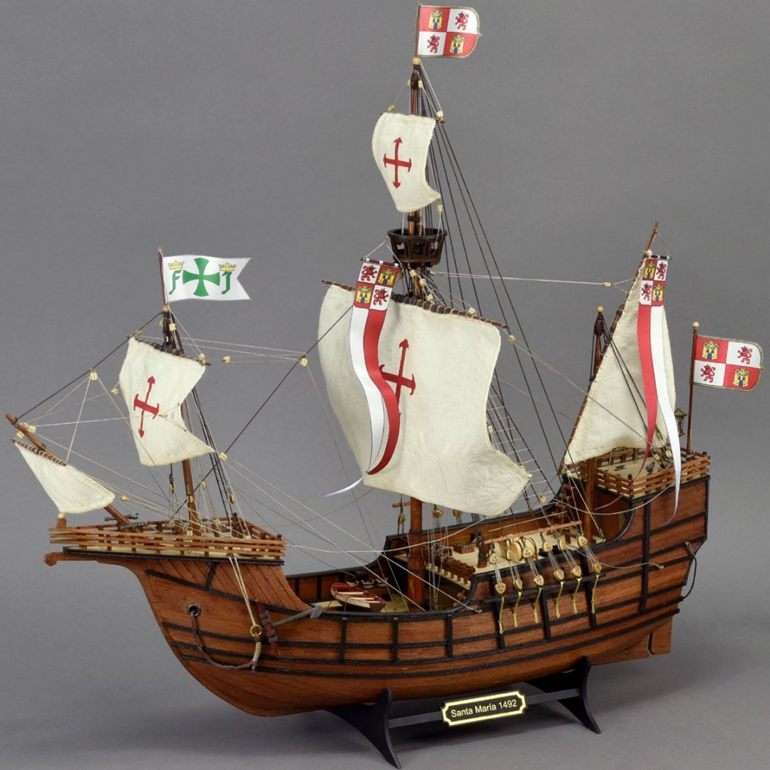
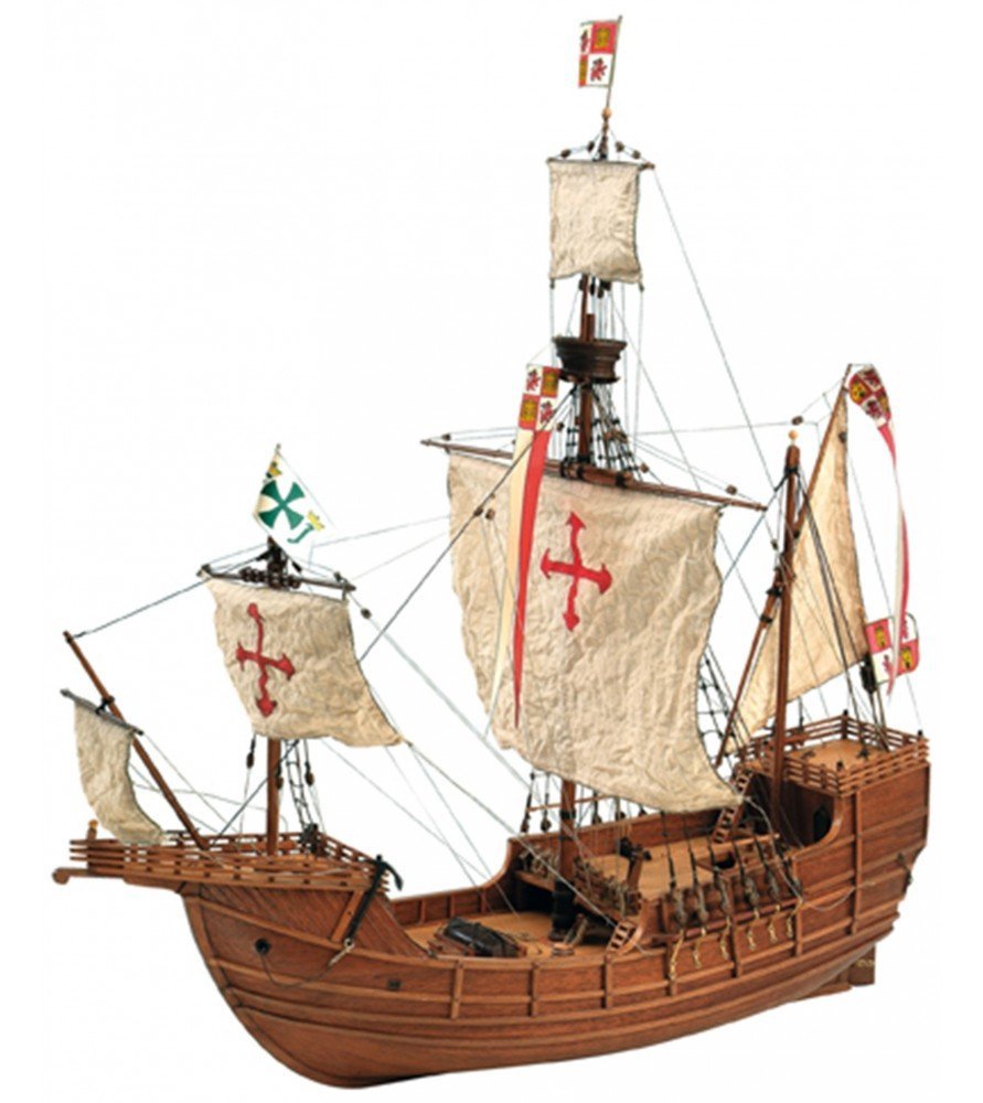
Hello, Dave. I was a tech engineer. My particular concern is transfering something that very useful but a bit difficult concept easily for mass people. Making an instruction is a bit tough for 2 years wooden ship modeller, so please consider my audience is the first builders only. Thanks, Dan. 1 presentation picture is better than 10 sencentes with wrong gramar. I checked how this 22411-N kit is different from the 30 years old 22411 kit. PJ did super fine research of Santa Maria replicas. Here is brief history of replicas. Year Type Reason / Builder 1892 Nao Quadricentennial Fernandez-duro 1927 Caravel Guillen 1951 Caravel Guillen's movie 'Caravel Santa Maria' Guillen 1964 Nao Martinez-Hidalgo 1986 - Theme park, Vancouver 1990 - Movie motor ship, Osaka 1991 Carrack Quincentennial Martinez-Hidalgo 1991 Nao Kobe maritime park Barcelona 1992 Carabela Celebración del V Centenario Isla Cristina 1998 Caravel Santa Maria de Colombo Robert Wijntje 2017 Nao 525th Anniversary The Nao Victoria Foundation I would say that there should be unknown Santa Maria 'like' replicas in the world... https://www.amazon.com/dp/1844860140 'The ships of Christopher Columbus (Anatomy of the Ship) published in 1992 is my reference book. This book includes 1892 Nao version, 1927 Caravel version, and 1964=1991 Nao version of Santa Maria plans. This is an old Artesania Latina 22411 Santa Maria kit from 1992 to 2020. This kit is same as 1964=1991 Nao Santa Maria by Martinez Hidalgo. I check the reference book, and found that the kit and the plan on the book is almost same. Looks like AL definitely received data from the builder directly. Here is new 22411N Santa Maria. Looks like almost identical. Only minor exteriors are changed and rigging parts get more complexed in my opinion. Actually, major change is inside construction and quality of wood. AL made an effort to add newest modelling techniques and beginner friendly manuals for easier work. As a result, It still looks 1991 Nao Santa Maria, and doesn't look like 2017 new Nao Santa Maria. I'll stick to the new manual and the reference book, so someone who finished old kit will see any differences very soon.
- 77 replies
-
- 2
-
-
- Santa Maria
- Artesania Latina
- (and 1 more)
-
Oops... I didn't change title? Also, this kit is different from 30 years old same name kit, so I added 'renewal' for search term.
- 77 replies
-
- 1
-
-
- Santa Maria
- Artesania Latina
- (and 1 more)
-
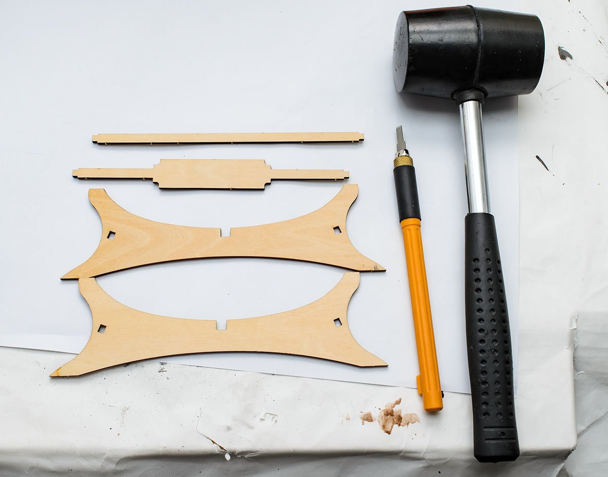
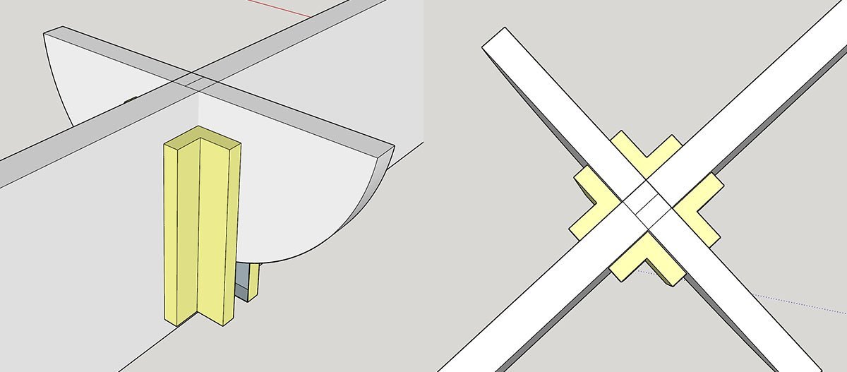
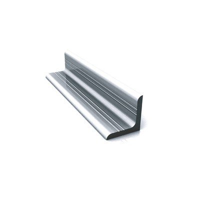
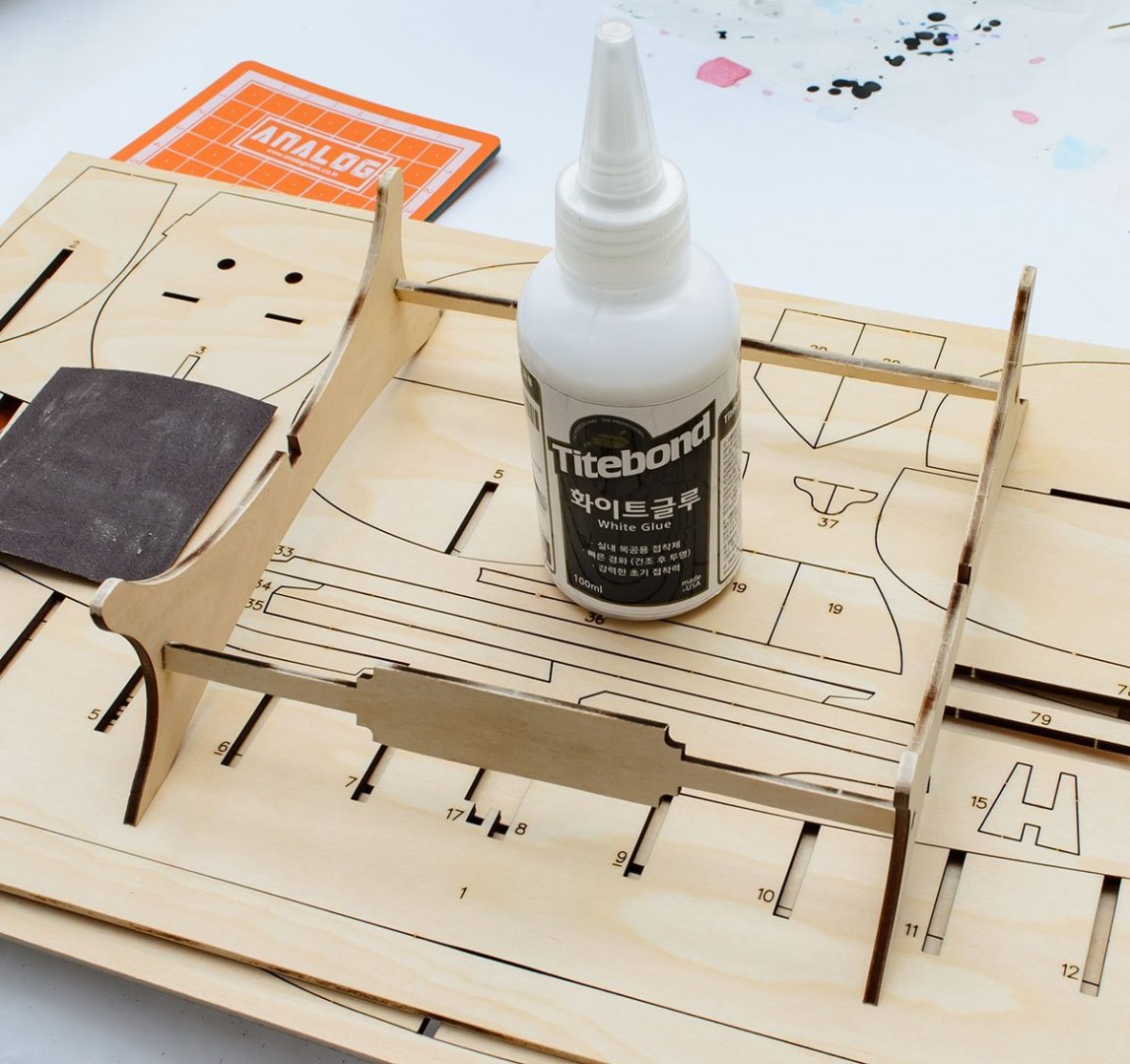
Happy new year! This is my first project of 2022. I finished lots of precise plastic models including two 1/700 photo etched warships last year. I would like to re-focus on wooden model ships this year. This build log will stick to manufacture's manual and very straight build in most case for faster progress. I hope you forgive me for low level of details. 😉 This is really useful review about revamped Artesania Latina Santa Maria kit. The kit is imported last week in South Korea. https://artesanialatina.net/en/home/62096-renewed-santa-maria-caravel-wooden-model-ship-kit-8437021128086.html In addition, you can download 101mb manual file which is also in a DVD in a box. Let's easy start with a stand. The manual page is 119. Parts numbers are 78, 79, and 80 x2. I used rubber hammer and OLFA AK4 art knife with 5mm width scribing blade. You can find the OLFA's 5mm scribing blade as Tamiya 74161. The white glue is the Titebond's 'No-Run No-Drip' glue which was 'Molding & Trim' glue in the USA. It is fast drying type PVA glue which reduces waiting hour 6 times. Titebond I is more famous, but I'm in favor of this bond's pure white color. Hammer time! Don't do this at night. Without proper alignment, you will face enormous amount of fixing work. The gaps are not tighten, and sometimes keel can be twisted. This is the ideal situation. You will have minimum sanding work for planking and deck installing. In reality, you need to align all three axises. If not, you have to sand bulged frames or reinforce short frames with straps. Both of them force unnecessary labor and time. 1. Draw lines 2. Use angle rulers or any kind of parts that make 90' angle. In this case, I used aluminum profile angles and clamps. I ordered 4x 100mm aluminum angles to get exact 90' angle. This is one of the accurate angle part and exceptionally cheap solution. (about 80 cents each) Here is a diagram how aluminum angles make exact 90' angles. 3. After I clamped a frame with 4 aluminum angles and 8 clamps, I measured length of port and starboard side of the frame. It should be same. This is the last progress of aligning axises. I used 4 aluminium angles and 8 clamps. Each frame takes about 10 minutes. Nice even result. This progress looks boring, but I promise that this is much better than quick hand gluing and later overwhelming work.
- 77 replies
-
- 7
-
-
- Santa Maria
- Artesania Latina
- (and 1 more)
-
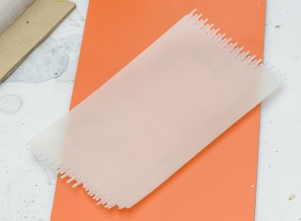
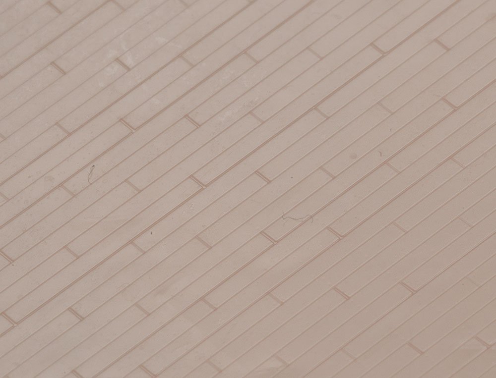
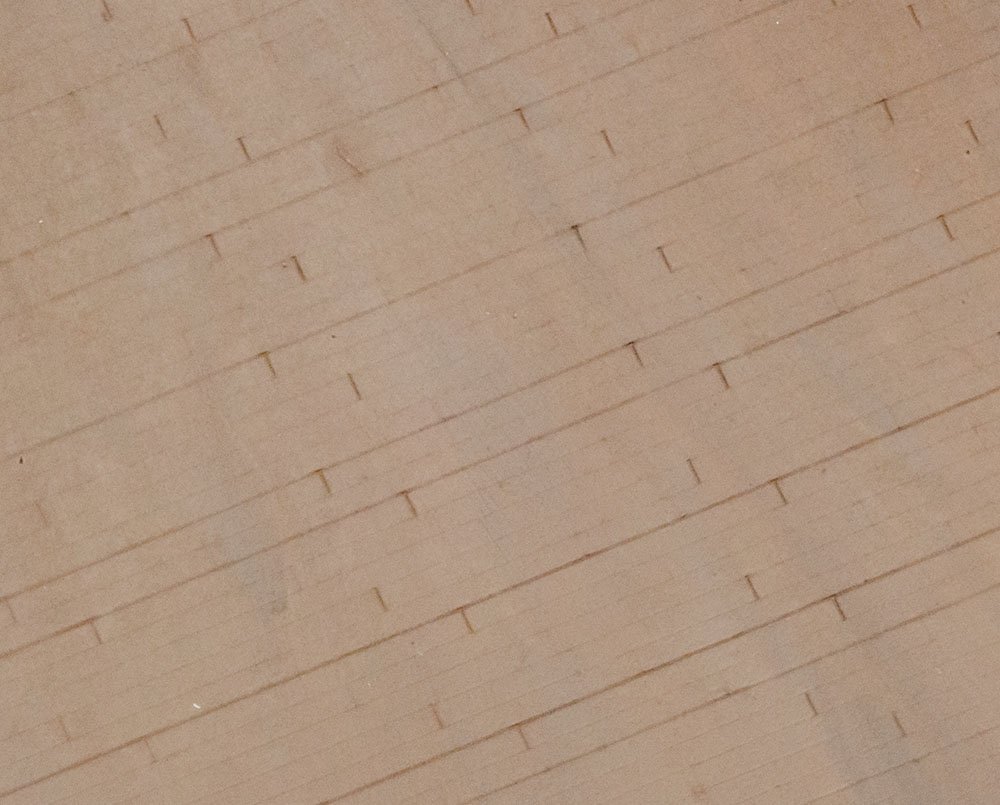
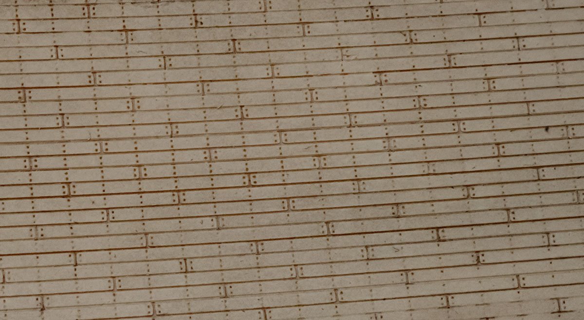
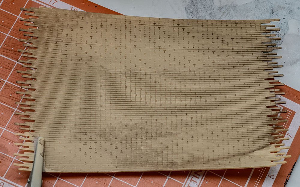
When I see real pictures of wooden deck, they are usually composed by several colored batterns. After I got your advice about realistic caulk lines in 1/350 scale, I found that I should focus on battern colors rather than explicit caulk lines. I saw some commercial product that has 3~4 layers of wooden deck stencil. The stencil templates has 4 butt patterned long square holes for airbrush which are engraved by laser cutter. With slightly different brown paints, the painting guide makes 'motley' wooden deck easily. It would be better to combine current result with my own laser cut painting stencil. In addition, I received 'wood' color resin for 3D printer. I'll print wood colored wooden deck and apply brown washing for faster process. Finding a way to make stencils will be a bit time consuming. I think it is time to buy Silhouette Cameo paper cutter.
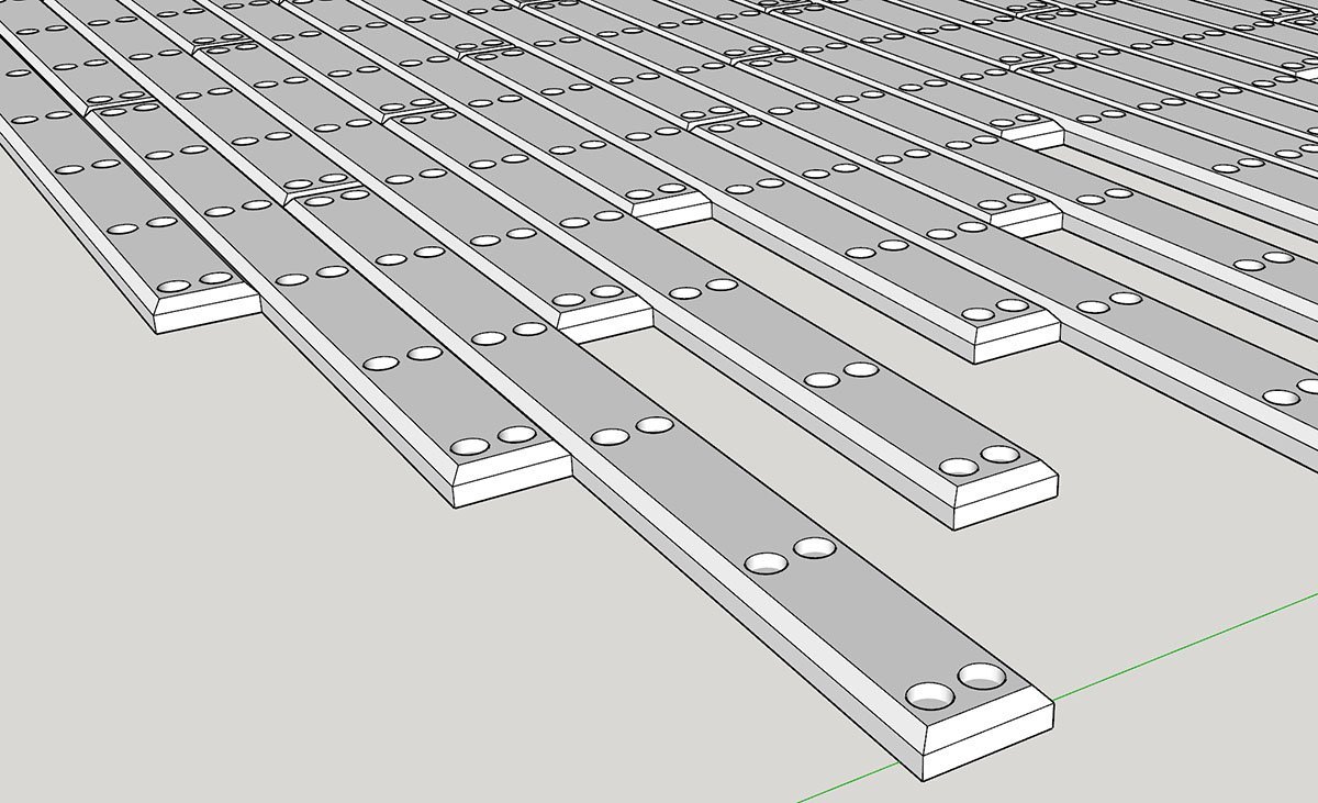
-
Hello, I have a plan to build scratch build 1/350 scale WW II ship in near future. By the way, I didn't want to pay $25 for 1.00mm width wooden deck sheet, and have fairly high resolution SLA resin 3D printer. I paid some time for boring work to save money and future time. This is my first rendering based on online and real wooden deck. The size is about 12 feet x 1 feet x 0.3 feet, and has some wooden bolts. As you expected, In 1/350 scale, it is almost impossible to distinguish each wooden batterns and bolt marks. I would like to oversized them in modelling expression. In addition, the 1 feet width in 1/350 scale is 0.87mm which is tough condition for my 3D printer. As I expected, my 3D printer couldn't handle wood bolts, and calk lines are too shallow. After one airbrush, most of calk lines are filled... I've polished 3D model, and printed it several times to get proper result. Trial and error is one of the most boring process when I develope micro scale 3D parts. 😭 The final 3D model looks weird, but in real condition, the huge holes and gaps between batterns will be filled. I applies Tan color lacquer and Vallejo brown washing. The panel lines and holes are still too shallow that only 2~3 airbrushing is acceptable. It may be a good idea to use wood color resin. The thickness is about 0.40mm. I think I can reduce it down to 0.20mm. Moreover, I may be able to stick the pattern when I print scratch build WW II ship. This is not comfortable and consumes lots of time. However, I got a fairly good wooden deck pattern that I may be able to use in the future.