modeller_masa
-
Posts
950 -
Joined
-
Last visited
Content Type
Profiles
Forums
Gallery
Events
Everything posted by modeller_masa
-
Question for full sail shape of spritsail
modeller_masa posted a topic in Masting, rigging and sails
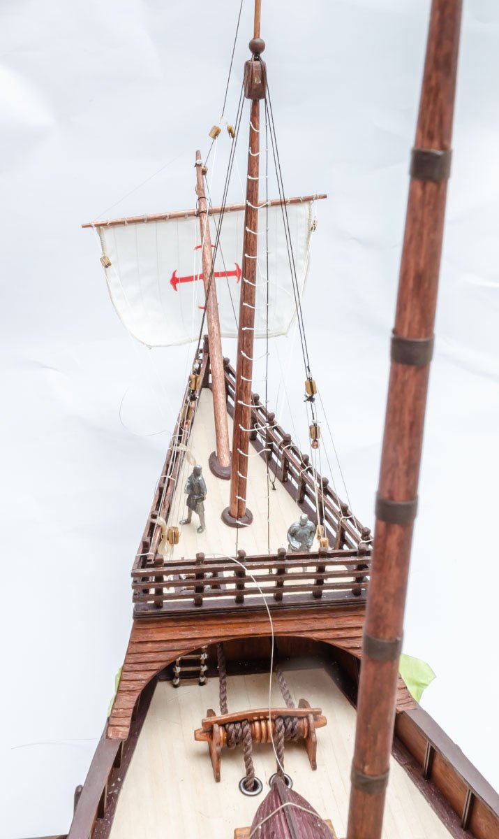
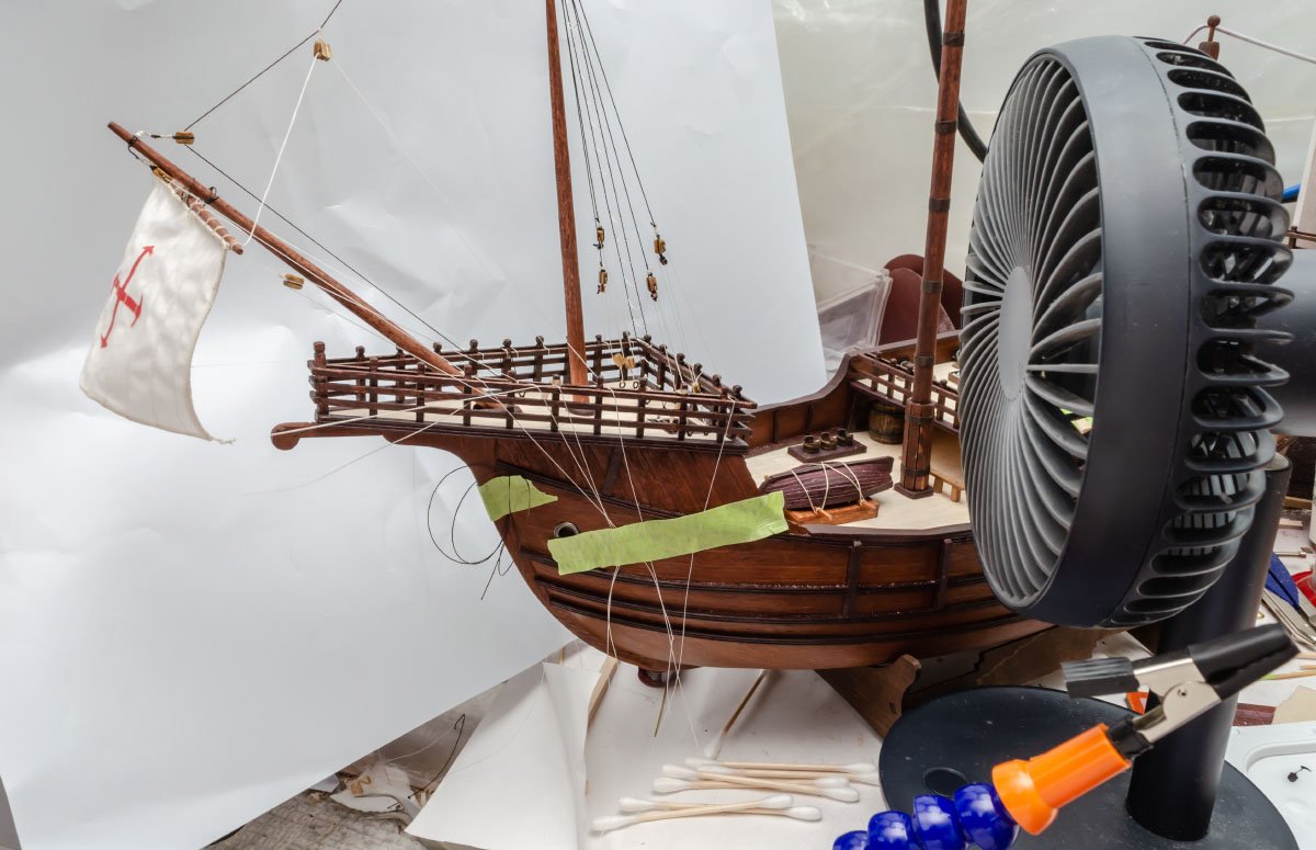
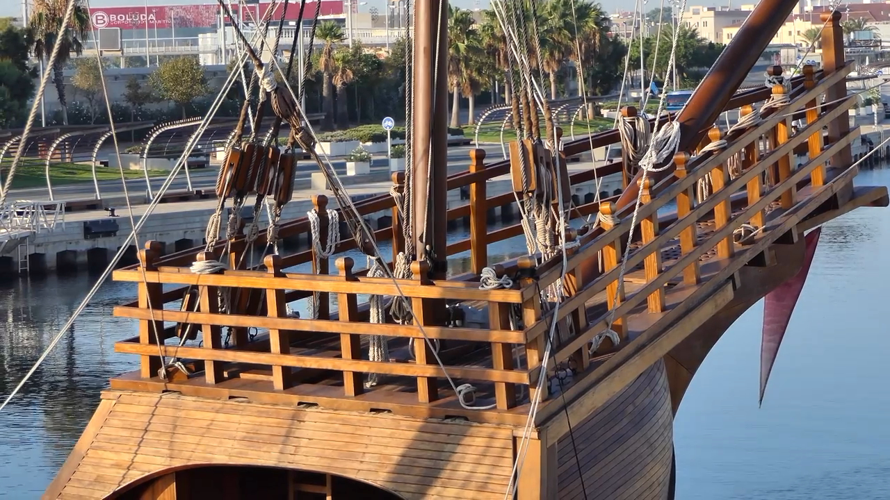
Hello, I have a question about a loose spritsail. As you see in the above picture, the spritsail doesn't stay in good shape without the fan. All the other rigging is tight, and only the "sheets" can't be tightened. The fullsailed spritsail is already stiffened by diluted PVA glue. The other sails, such as the foremast sail, have front rigging lines to lift up sails, but only the spritsail doesn't. I don't want to replace the sheets with white floral wire. I remember that some modellers include steel wire inside of the leech lines, but it seems to be a little late to apply. Do you have any idea to lift the spritsail a little bit and tight all the riggings?
-
Of course, yes. Some varnishes, such as wax for wood, don't allow any bond, but most of them still have good adhesive to additional deck fittings. I would recommend the dewaxed shellac from Zinsser's. Shellac is a nearly all purpose varnish and bond for wood and thread. - Dry within 15 minutes. (Faster than oil and water based varnish) - Safe (Alcohol based) - Convenience (A little bottle of shellac lasts for a few days.) - Easy removable (Ethanol or IPA) - Nice coat (A little yellowish satin surface - not glossy) - Long shelf life (more than 5 years + add some alcohol to thin) - Application - Nearly all place of wooden model ship! Wood conditioner ◎, wood varnish ○, great paint primer (especially metal surface) ◎, good bond for thread and knot ◎
-
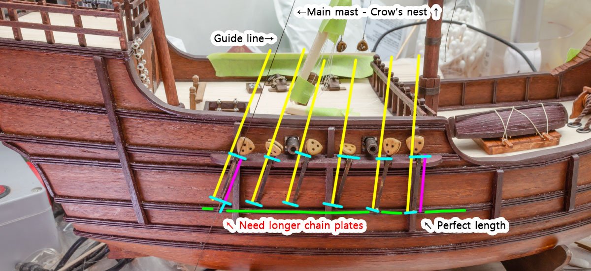
I found that my build log is following Richard Feynman's study method. When he finished to study something, he made a lecture note to confirm his study achievement. https://medium.com/taking-note/learning-from-the-feynman-technique-5373014ad230 1. Identify the subject 2. Teach it to a child - Speaking in plain terms - Brevity 3. Identify your knowledge gaps 4. Organize + simplify + Tell a story ← This is my build logs. Therefore, I'm drawing a very effective learning curve used by a novel prize-winning scientist! 😎 The main stay and foremast shrouds are both overlapped. It is better to remove the "clueless" foremast shrouds. I modified the photo etched chain plate parts like the 2017 Nao replica, but its length caused a minor issue. The opposite side. You can see the nails of the chain plates going up. It is better to make DIY chain plate parts using 0.15mm brass sheet.
- 77 replies
-
- 5
-

-

-
- Santa Maria
- Artesania Latina
- (and 1 more)
-
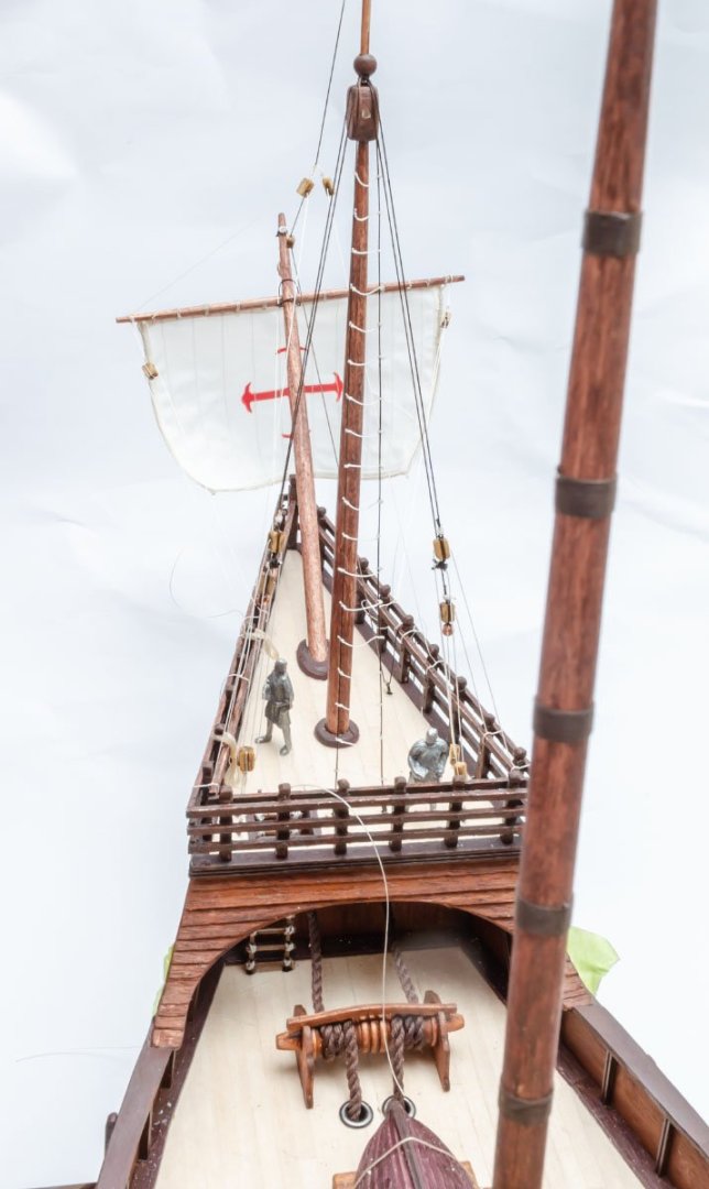
I made a shroud for the foremast. The ratline (white threads) should be wave shaped. To make the ratlines wave, I paid attention to the knot. After I finished all the rigging work for the spritsail, I stiffened the sail in full wind form. I simply used a portable fan and diluted PVA glue. (water 1:1) Challenging and exciting project.
- 77 replies
-
- 2
-
-
- Santa Maria
- Artesania Latina
- (and 1 more)
-
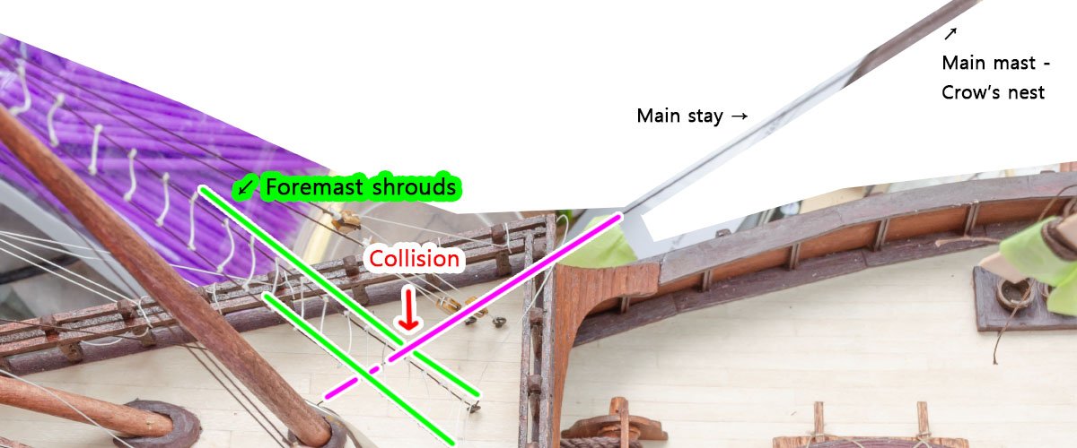
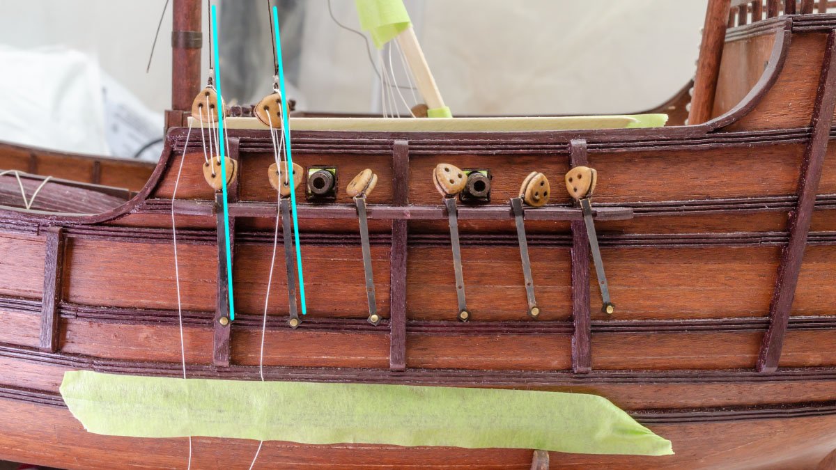
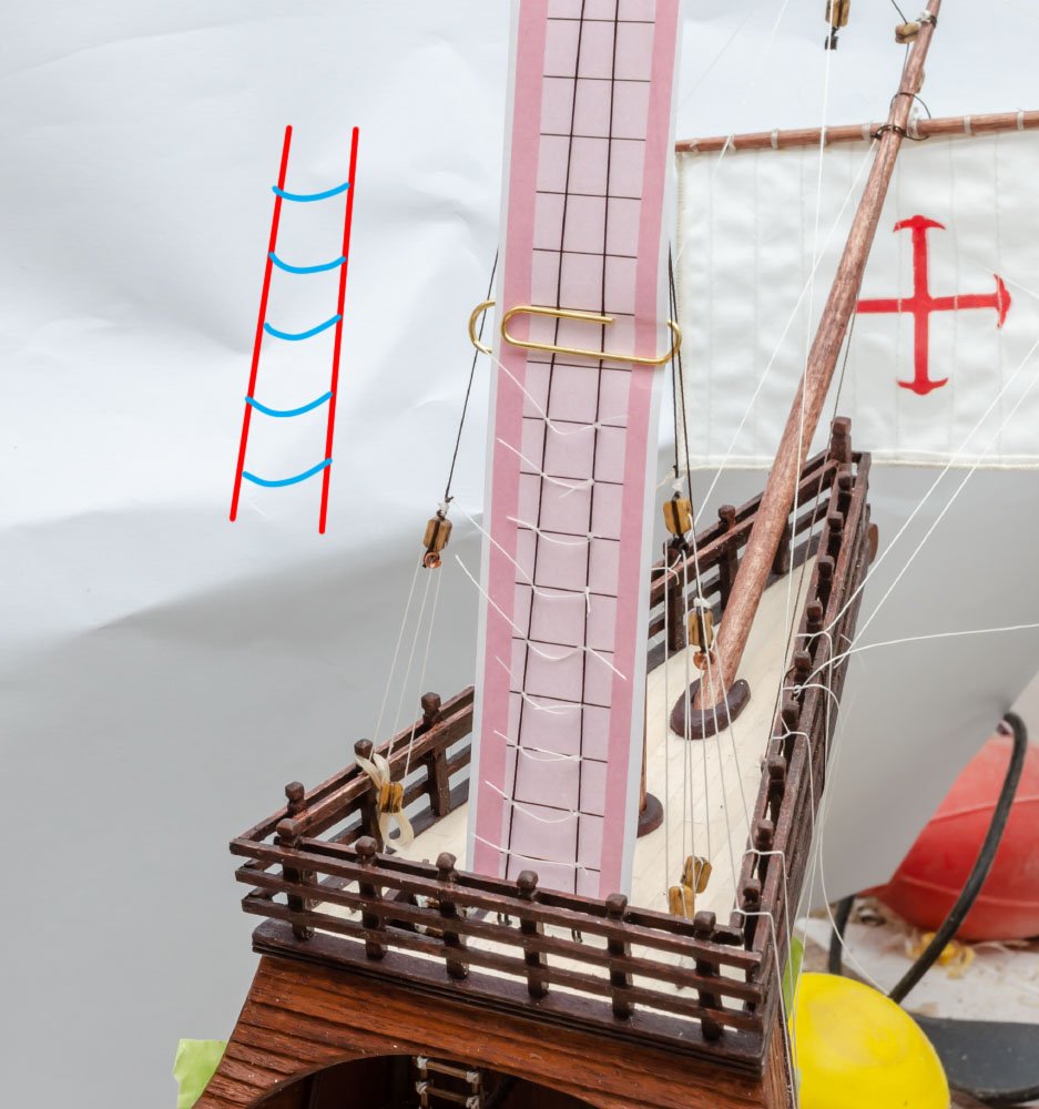
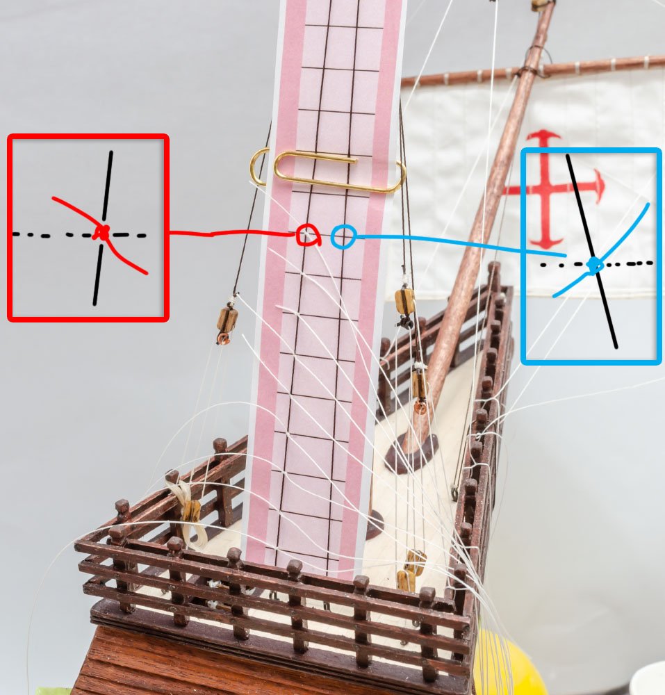
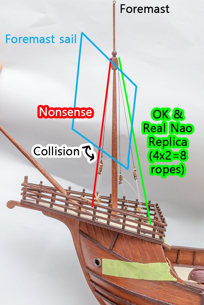
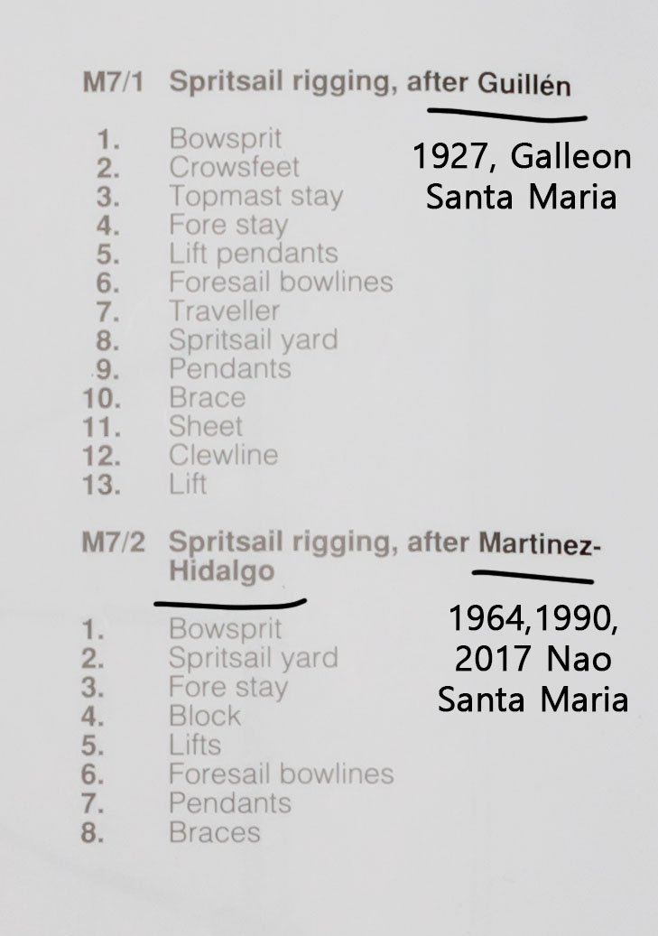
This is a minefield. With every step I take, my rationality sensor says the instruction is something wrong. Then, I have to dig into the issue and fix it for several hours. It takes too much time... There are 2x2 standing riggings that support the foremast. Look at the red threads. I doubted it wouldn't let movement of the foremast sail freely, so I decided to move it backward, just like the real 2017 Nao SM. In addition, I found that spritsail doesn't work well explicitly. After several hours, I found the reason. AL faithfully followed the reference book, and they combined both rigging diagrams of Galleon SM and Nao SM. As a result, the functions of some rigging threads are overlapped or useless. This kit is basically Nao SM, but I already found that some parts of other areas are from Galleon SM. And, how did they combine both rigging methods into one sail? Moreover,some blocks share multiple ropes in a hole because of cost-cutting. At least it works on model ships, but it doesn't in reality. I think sailing ships in the 15th century were the most advanced weapon like F-22 raptor in the 21th century, and every part has a reason to be there. If airplane changed or removed some parts like AL did, the airplane will crash before it reaches a destination. As previously stated, Columbus wouldn't have discovered the "India" with this instruction.
- 77 replies
-
- 2
-
-
- Santa Maria
- Artesania Latina
- (and 1 more)
-
The first ropes are from the foremast. (Source : https://www.youtube.com/watch?v=M871OrwsYLg ) https://www.hnsa.org/manuals-documents/age-of-sail/textbook-of-seamanship/tackles/ I couldn't understand the AL's instruction, so I searched for structure of the tackles. According to the maritime dictionary and the 2017 Nao replica, it must be a gun tackle purchase. I bent copper tubes and made a ring under the blocks. The idea is from someone's build log .

- 77 replies
-
- 2
-
-
- Santa Maria
- Artesania Latina
- (and 1 more)
-
Thread Zap - thread cutter
modeller_masa replied to modeller_masa's topic in Masting, rigging and sails
I tested another way to shrink nylon thread. I used a digital temperature controlled soldering iron and set it at 250℃, which is slightly lower than the melting point of typical nylon, 265℃. As a result, I was able to control the shrink speed and area successfully. The nylon's melting point is from 220℃ to 265℃ in general, so please test your nylon thread before applying the soldering iron.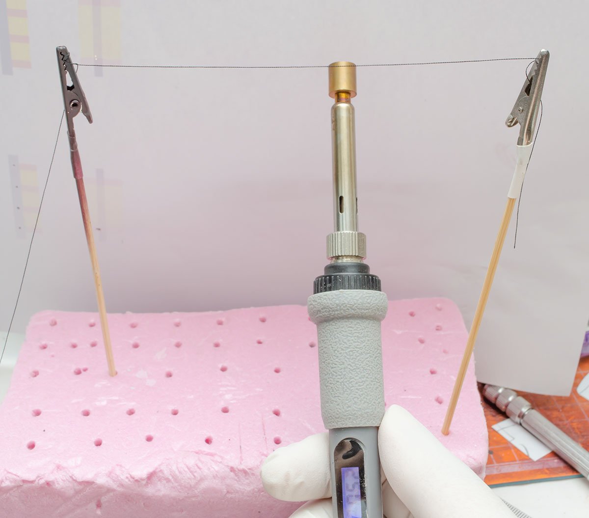
- 1 reply
-
- 3
-
-

-
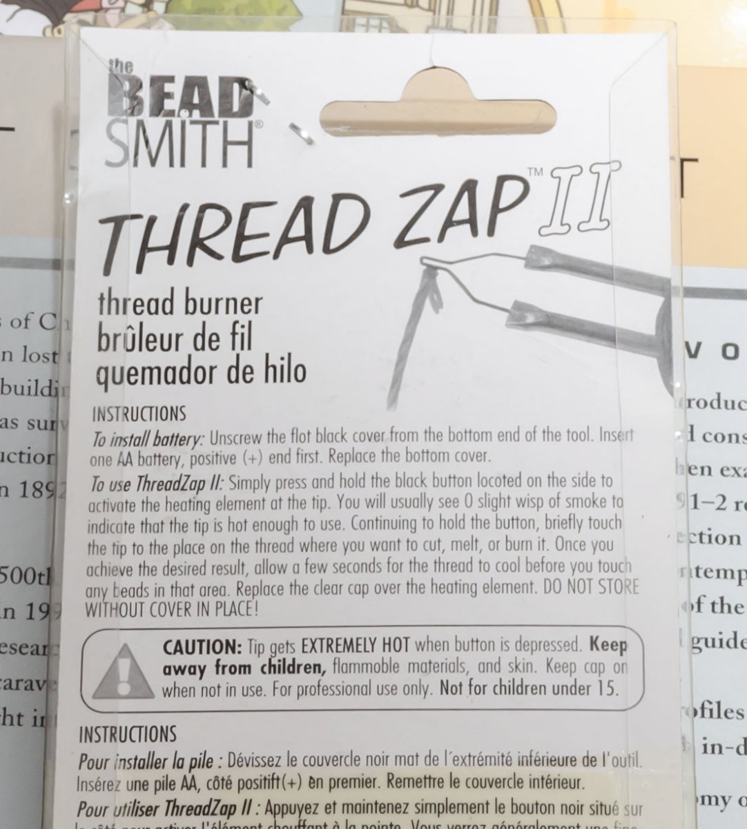
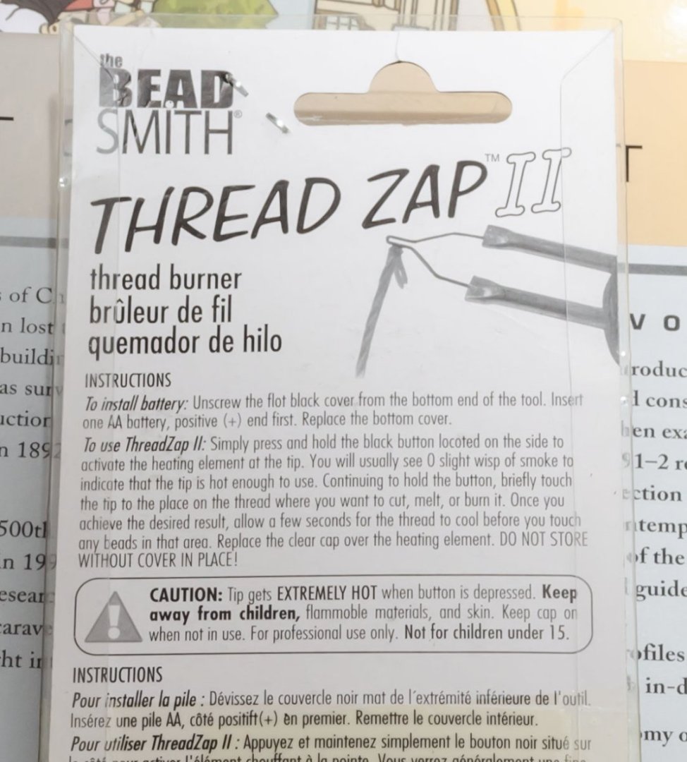
Hello, I purchased portable soldering iron for rigging. This small and portable iron burn threads up to 1000℃. This is my review video. Poly - Best cut & tip scorching Cotton - Best cut, but never try to scorch a tip Nylon - Best cut & tip scorching In the last lecture, Strategic Detailing Part II by Chuck Bauer, he shared a tip for burning shrinkable nylon thread when he made a 1/350 scale models. This iron is a bit dangerous for scorching the nylon thread, but I would say it may be more stable than a matchstick. Also, be careful when storing the iron. Its protection cap is vulnerable, so that it is best to remove the AA battery after work.
- 1 reply
-
- 3
-
-
-
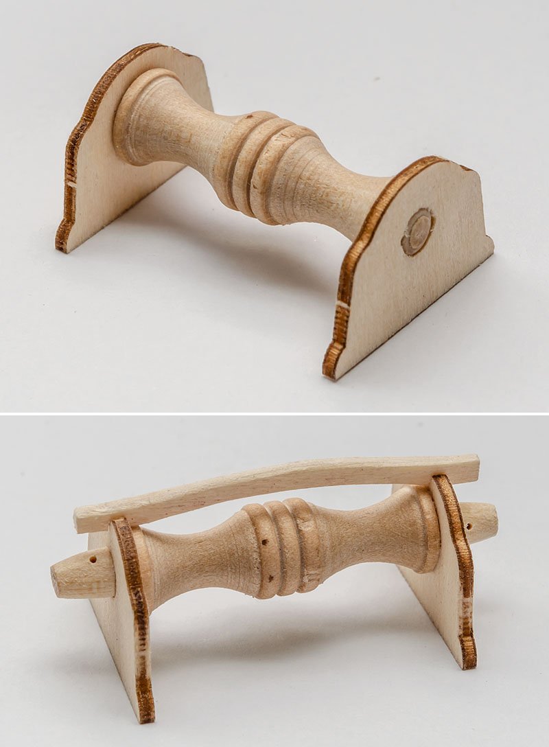
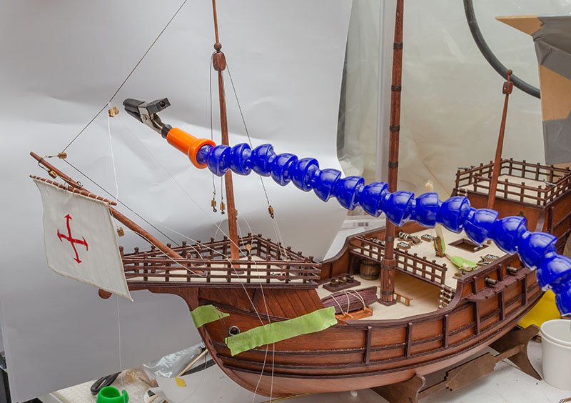
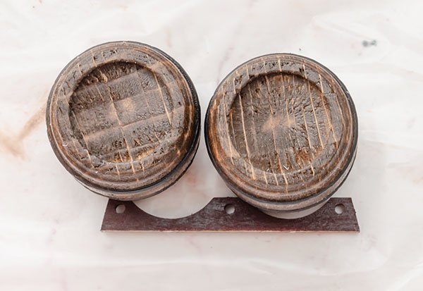
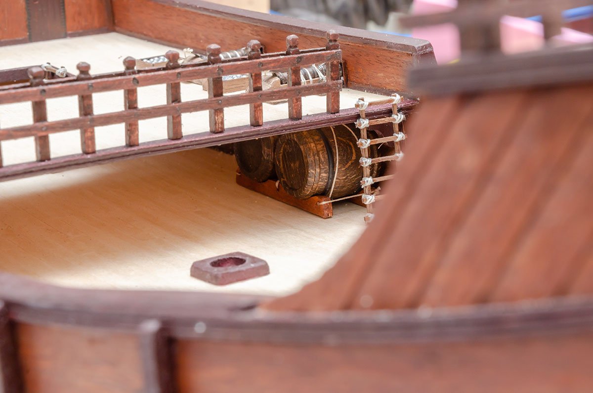
This isn't a scale error, but incorrect parts. The barrels are much bigger than the instructions' barrels. I made a custom barrel stand, but its overall look was ridiculous. I decided to hide the wine barrels in a corner of the deck. Here is how the entire ship looked before I started rigging.
- 77 replies
-
- 3
-
-
- Santa Maria
- Artesania Latina
- (and 1 more)
-
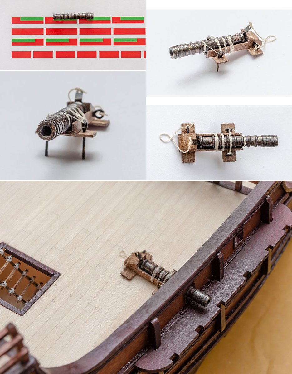
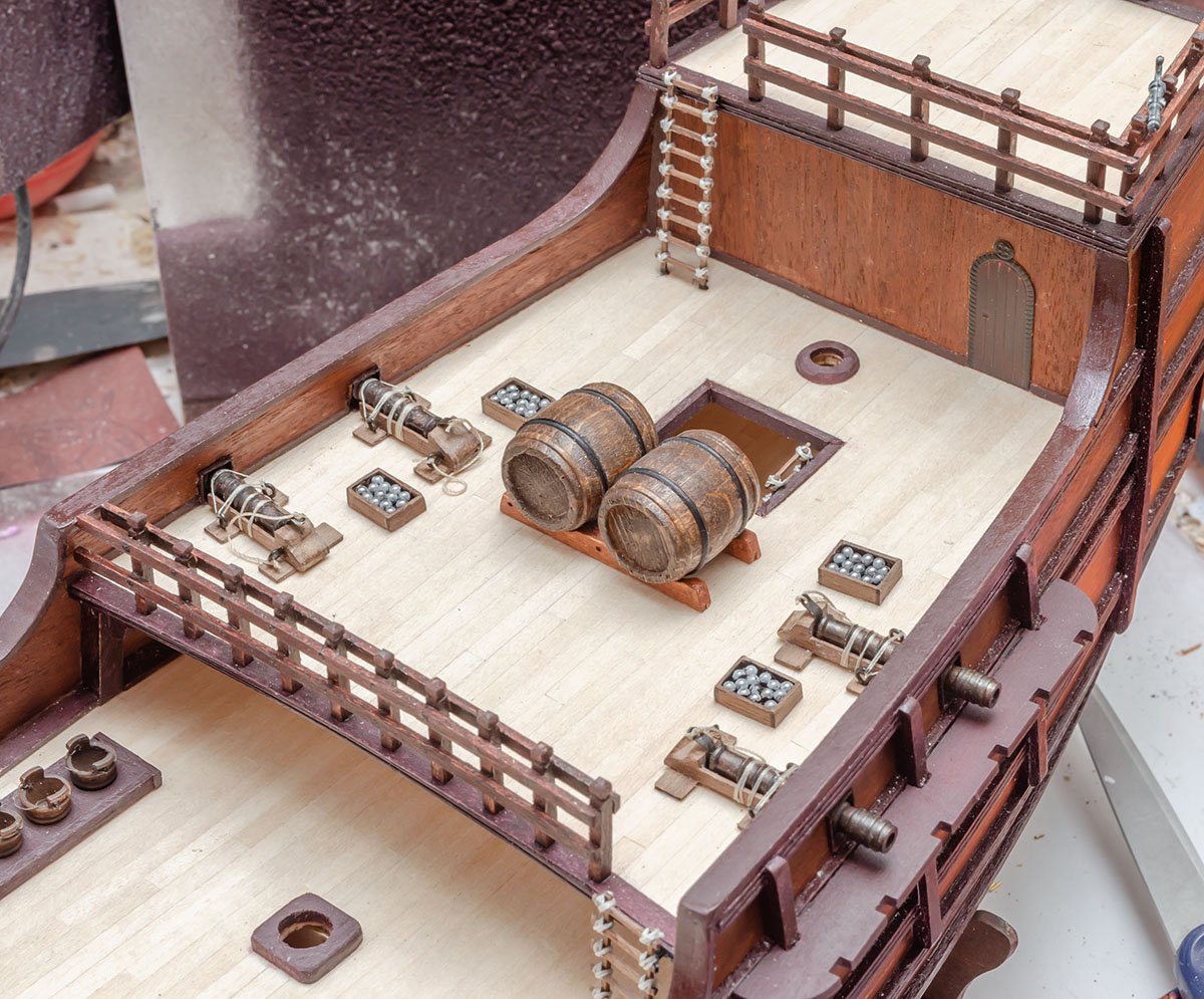
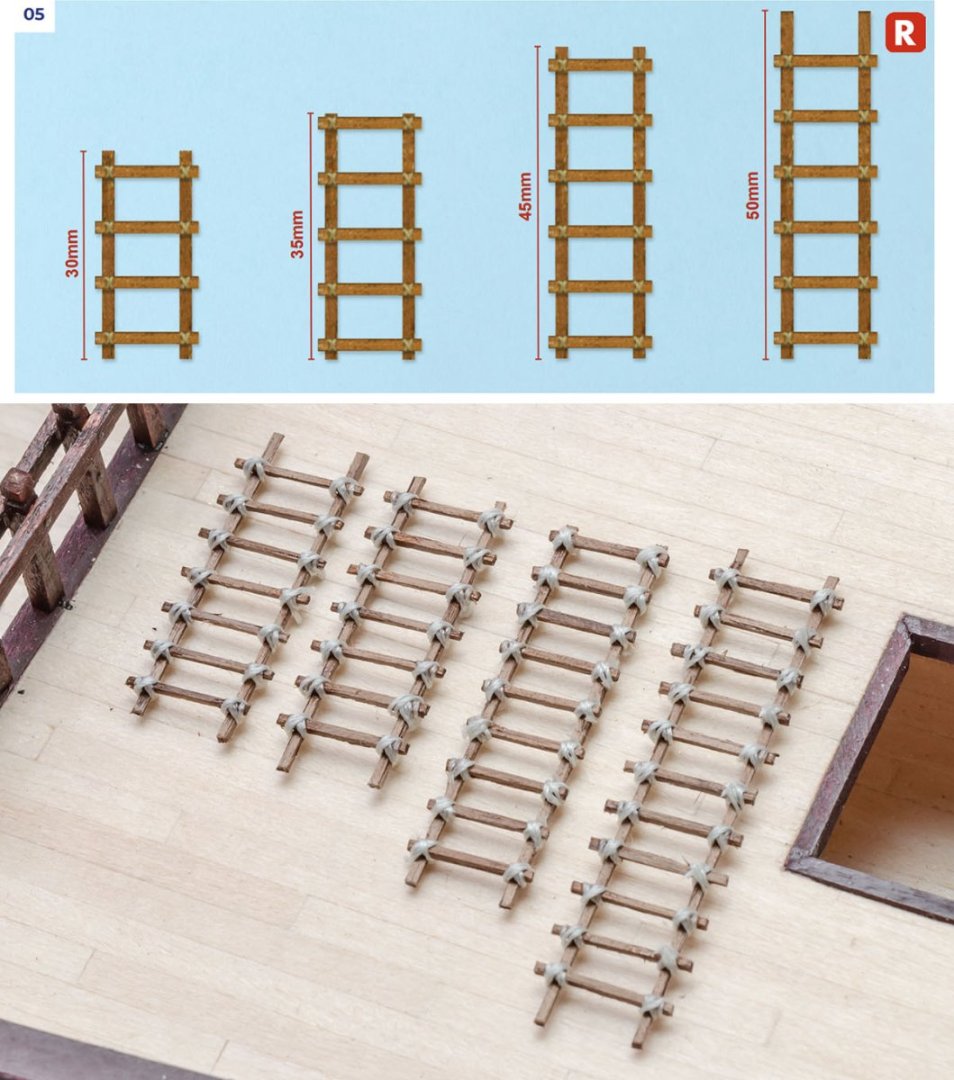
Almost all parts in the kit are overscaled. I reduced the thickness of ladders from 2mm to 1mm and decreased story heights from 520mm to 300mm, which is the international standard. Sailors should praise me. Here is double issue. First, Nao SM on the reference book and real world replicas doesn't have a windlass. The AL's Nao SM kit includes a windlass, which was in the galleon SM in 1927, instead of a capstan. Of course, history keeps silent, but contemporary Nao ships in 15th century installed capstan in the middle of the ship in general. If I had completed the NRG capstan project, I would have made and added it. Secondly, the default windlass shape is simple and lack of details. I modified the default windlass a little bit. The Breechloading lombard cannon is also overscaled. Its diameter is twice larger than the reference book's. I followed the gun stand in the reference book. I also studied the structure of the Lombard cannon. It seems to be pretty primitive and understandable, so that I designed the gun stand and rigging to be workable. The result. Make sure the gunfire doesn't cut the shroud cables.


- 77 replies
-
- 4
-
-
- Santa Maria
- Artesania Latina
- (and 1 more)
-
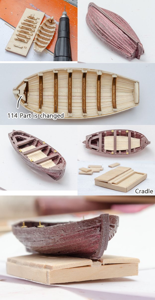
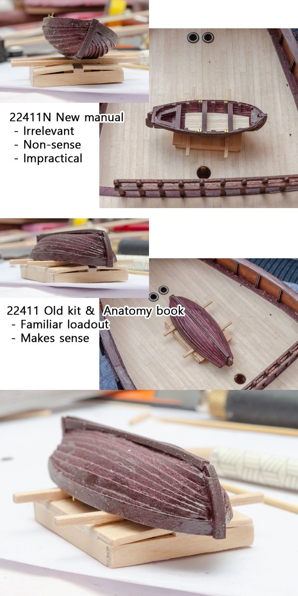
I appreciate knowing the new information, Veszett Roka. I still think that AL forgot to add some details, such as waterproof cloth and a V shaped cradle, when they simply turned upside down the yawl. Also, it's a bit inconvenient to see an inclined boat... I'll choose the old kit's arrangement rather than the new kit's. Thanks again for your comment.
-
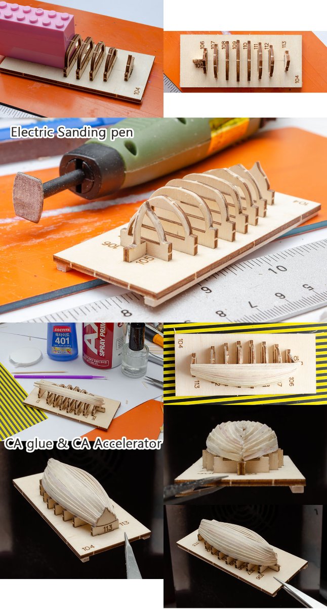
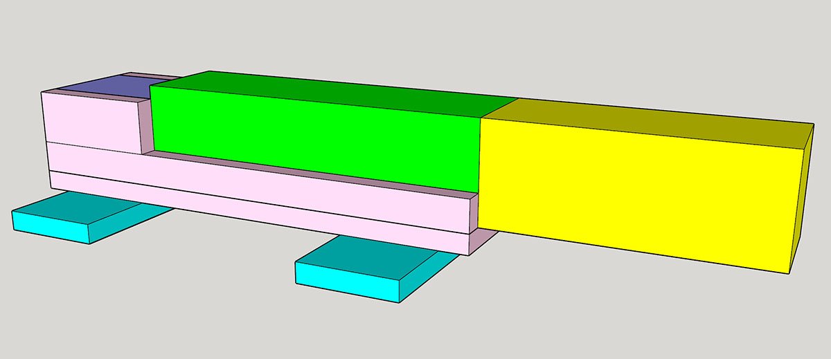
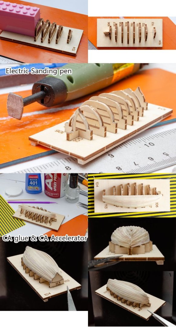
I finished sewing custom sails but am having difficulties forming wind sails. (I failed to apply a technique I planned.) I skipped to the other parts for now. The AL kit includes only yawl, and launch isn't in it. I used an electric sanding pen. It is the best for sanding sensitive and tiny parts. The new AL kit includes a better boat building kit instead of a metal bowl. If you are having difficulties on building such small boats, I recommend you build the Falkonet's mini boat series. They are great educational tools for new builders. One of the AL's weaknesses is insufficient polishing on a kit. AL's laser cutting isn't highly accurate, unlike the most recent kits from some innovative companies, so the hull of the boat can be twisted by margin errors. And, probably, it is the most dislike point of the AL by serious builders. AL rotated the cradle position and flipped around the boat like furnitures in a doll house. It is related to the structure of the ship, and pillars of building can't be moved that easily. I agree that the upper direction is more "visible" and add some details on the deck, but viewers will think and ask me, "How did the real ship bind the lifeboat? The unstable boat should fall in the storm." "...... I just followed the instructions, so it's not my fault." Oh, I really don't want to break a viewer's immersion. Even if it is a SF fiction model, the model should explain its shape without TLDR.


-
Tested : Heat transfer paper for painting sails
modeller_masa replied to modeller_masa's topic in Masting, rigging and sails
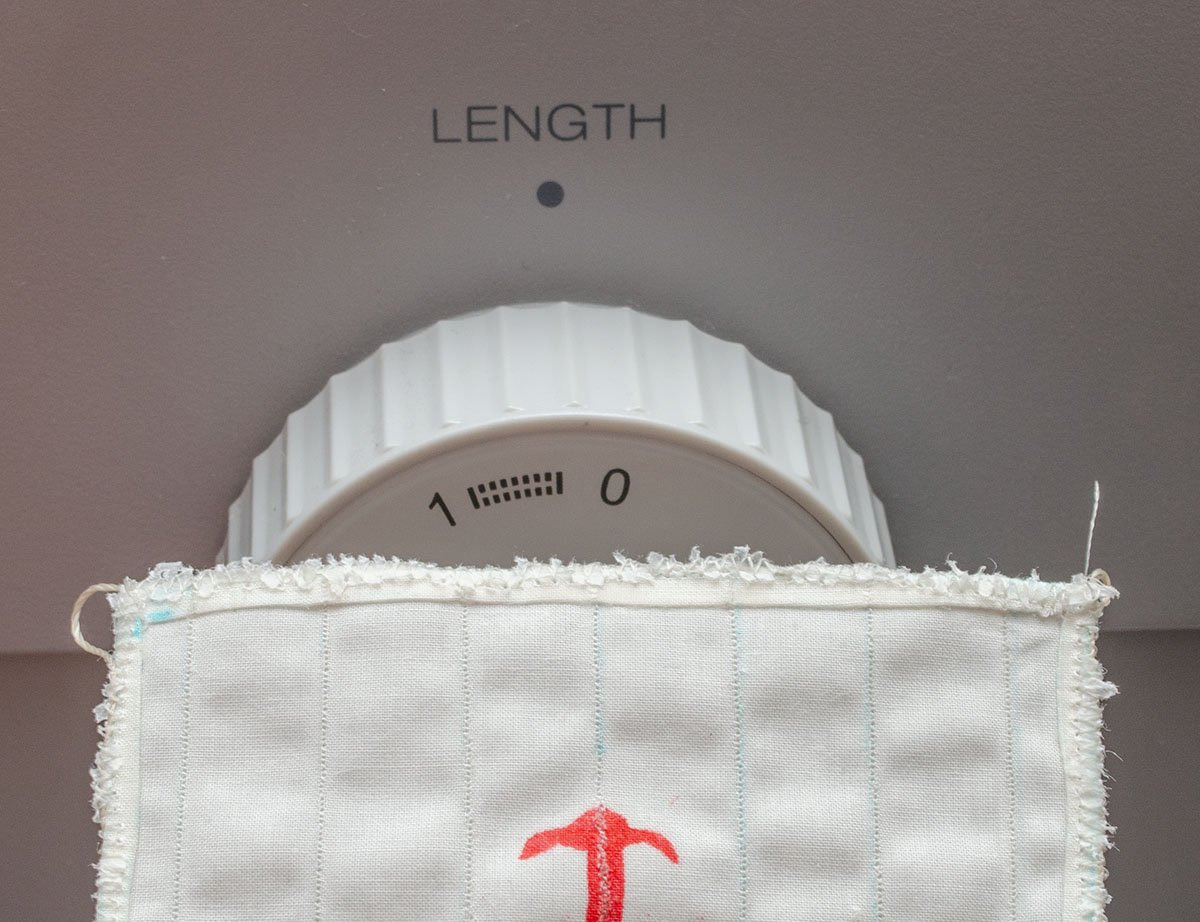
I got a good result on both sides. Here is a method. It's not very difficult. 1. If you need to, print one of the transfer papers reversed. 2. Leaves marks on the papers and the fabric with a water-eraseable pen for fabric work. Completely sync them before ironing them. 3. Increase the time spent ironing. Press for 30 sec and rub for 5~10 sec. 4. Remove both transfer papers immediately. 5. Ta-da! One more thing. I have difficulty with sewing from the end. Because the sails are relatively small and the fabric is folded mutiple times, feed dog bites it and cuts the feed threads. There are some general methods to overcome the issue. (1) Stop using feed dog : use free motion foots such as a quilting foot - The quality of the sail can be worse because of inconsistent stitches. (2) Replacing to a single hole plate : -Cannot use the zigzag stitch. (3) Putting a thin paper foil under each jamming point : -Causing issues when the length is too narrow (above picture). (4) My solution: putting a water soluble paper under each jamming point. Never Kleenex, Never toilet paper.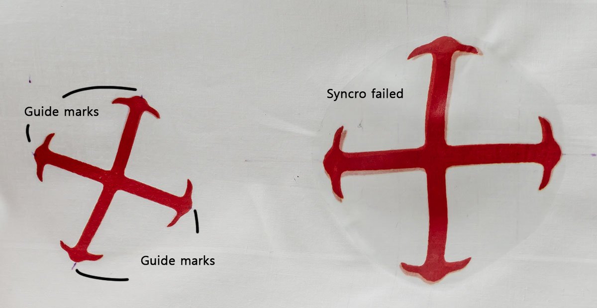
- 1 reply
-
- 5
-
-
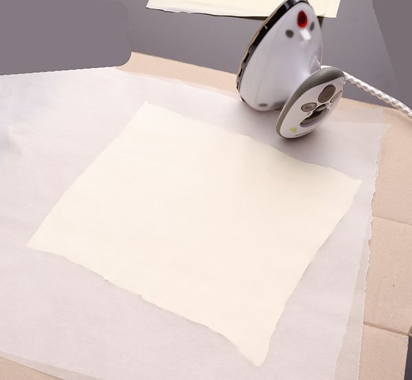
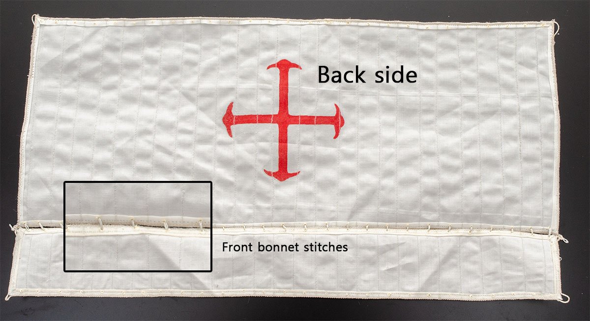
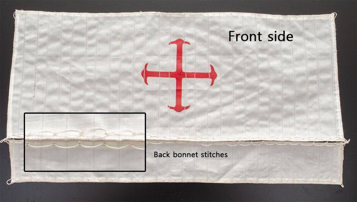
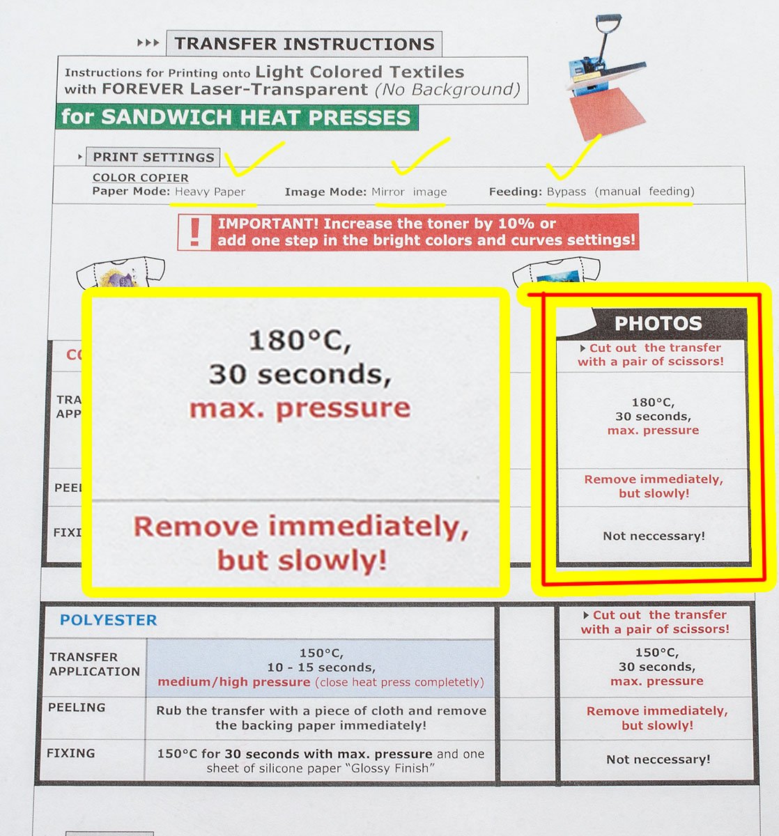
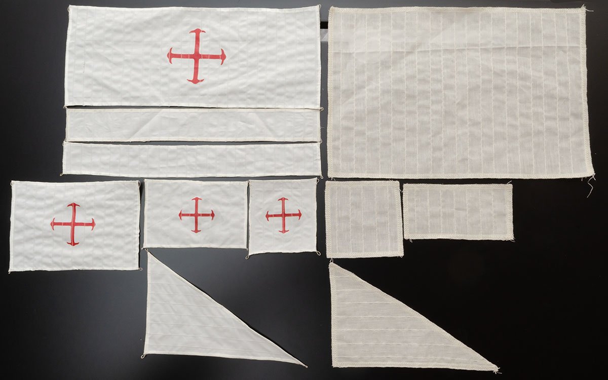
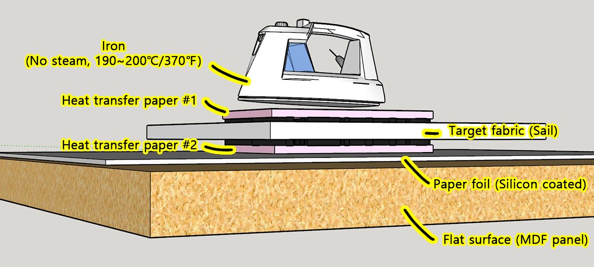
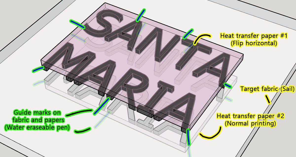
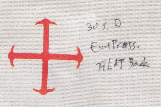
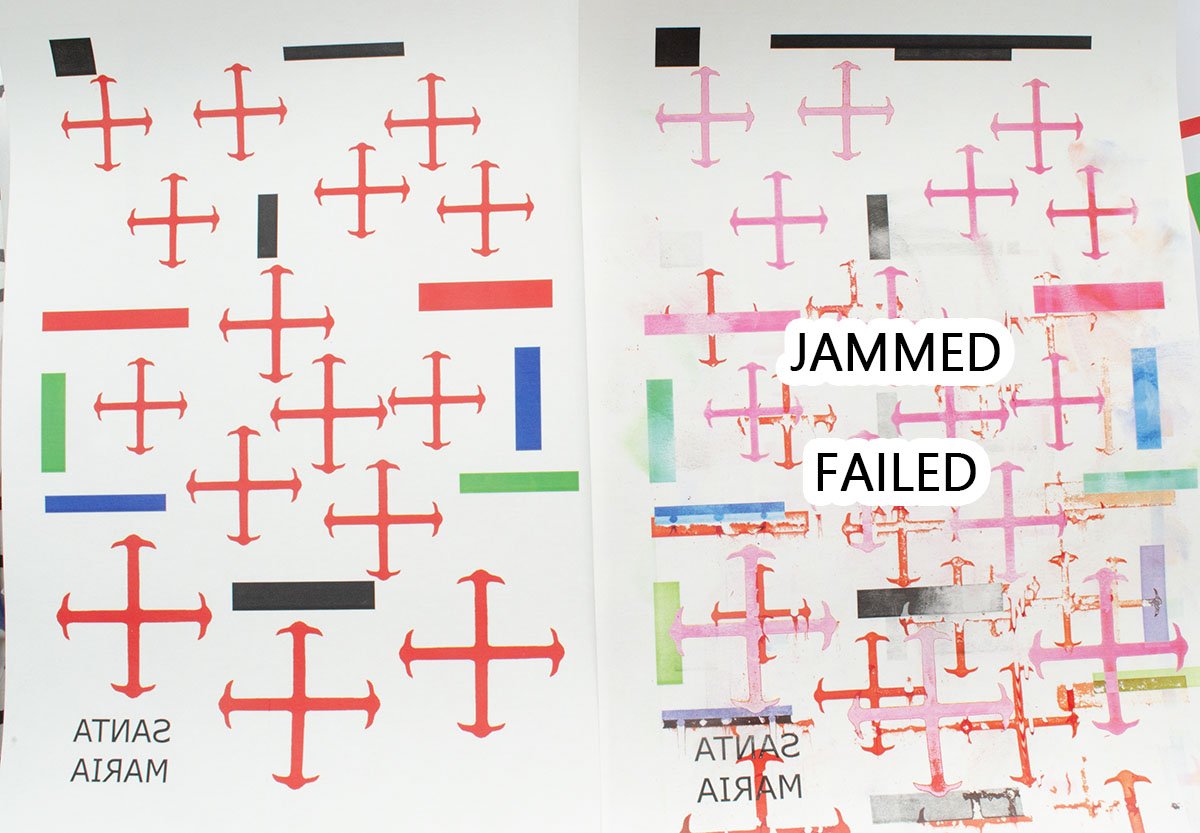
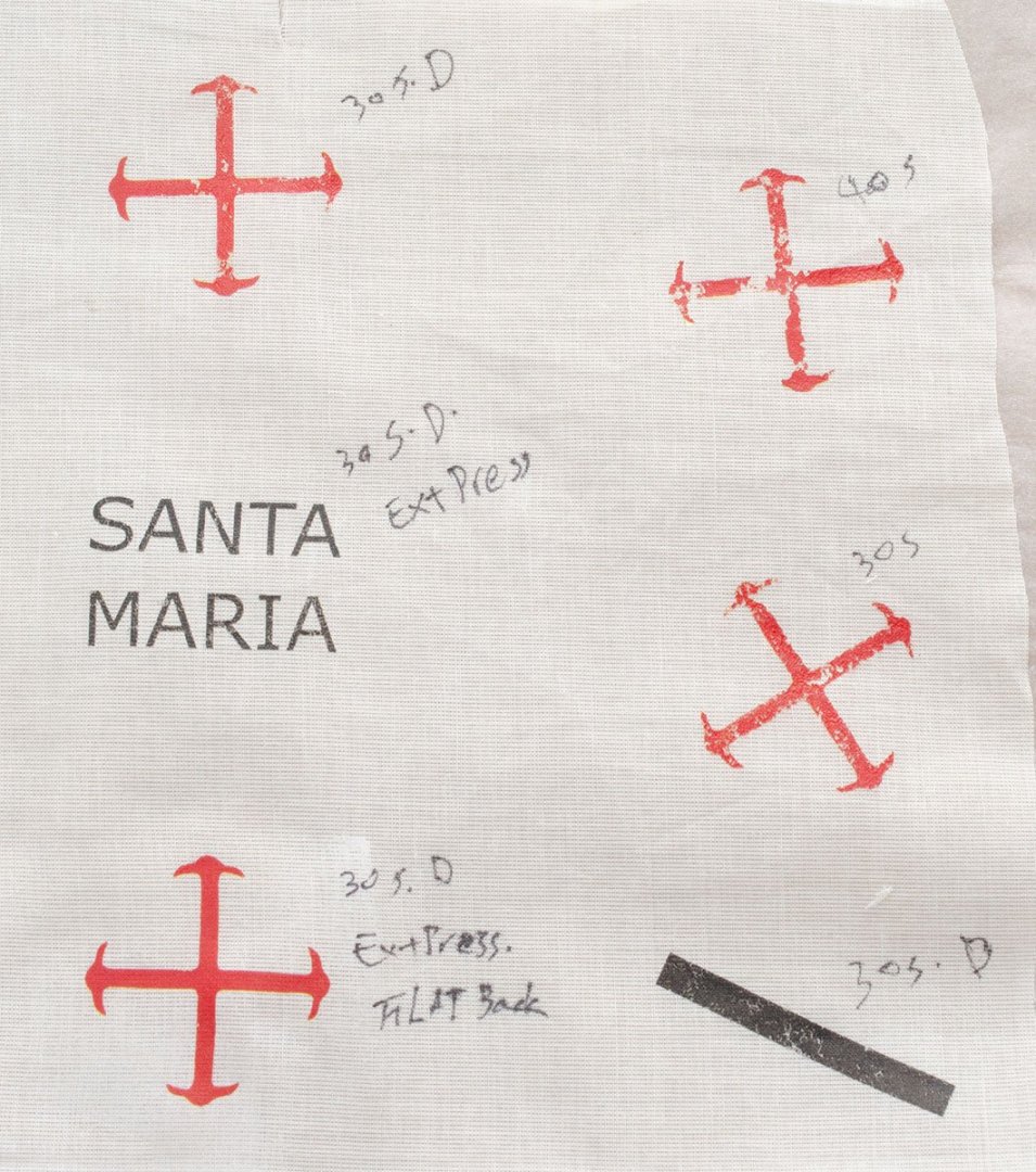
Hello, A long time ago, I posted an idea about using heat transfer paper that is commonly used for T-shirts. I've tested some heat transfer papers and related techniques, but I would like to summarize my only successful result here rather than upload many trials and errors in the old post. Also, there are only limited resources to meet the high expectations of this forum. * Requirements - Common digital temperature controlled irons, such as Tefal steam irons: I won't use the steam. - Flat and durable table or a MDF panel an half inch thick: I'll press it really hard. - Clean paper foil for kitchen - (Color) Laser printer - Forever's laser transparent transfer paper (Made in Germany): Make sure the background is clear or nothing. White or black isn't what we need. https://www.amazon.com/dp/B01M7YDHTG * Official guides As you see from Amazon's worst review score, the transfer paper is very sensitive and hard to use if you don't know how to take care of it. https://youtu.be/N1CAx5KrfJ4 https://youtu.be/qXsZ3wWA6sk There are some useful video tutorials, but you still need some trials and errors before use. Here is a cheat sheet from the manufacture. There are 2 choices on the paper because I used cotton fabric, and I already wasted lots of transfer paper and fabric to test the first trap. 🤪 Forget it and follow my guide. Step 1. Printing the heat transfer paper carefully. (1-1) Check your laser printer. If your laser toner printer is a popular type, it shouldn't have a bypass printing mode. In that case, hold and pull the printing off the paper by hand. Otherwise, the expensive and thick transfer paper will be jammed and become useless. Step 2. Setting a flat ground (2-1) To iron, place at least a half-inch thick MDF panel or secure a flat table. (2-2) Cover the surface with a silicon coated paper foil to protect cotton fiber from dusts. Step 3. Preheat an iron to 180℃ or 355℉ (3-1) Use a noncontact thermometer or set it between wool and cotton. Step 4. Riding on the iron (4-1) Position the transfer on the fabric and press it with all your might and weight for 30 seconds. The youtube video explains it as 3~5 bar pressure. Don't cover the paper foil on the back of the transfer. (4-2) After 30 seconds, remove the transfer carefully and immediately. Be careful of burns! The transferred image is quite durable and doesn't dissolve in water. It also works well with PVA glue. All the progress is very fast and fun to compare with brush painting or stencil spraying I tested. I guess this technique may be good for beginners and those who want complex and unique flags. ------------------------ This method increases the success rate up to 90%. (1) Increase the temperature by 10℃ (or 16 ℉). (2) Press the transfer paper for 25 sec, and gently rub the paper with the iron for 5~10 sec. Almost all commercial steam iron have holes, so they don't have a flat surface, which causes imbalanced force. (3) If you removed the transfer paper without any residue, you are good to go.

- 1 reply
-
- 9
-
-
-
This isn't a solution for Mark, but I would say that some warping issues can be prevented by clever mechanical woven joint design. This kit is from Maris Stella's B.C.440 Monoreme, and its unique joint design (red-slot and azur-walnut strip) effectively prevents hull twisting, helps to align frames precisely, and offers good guidelines for deck planking at once. This is one of the most briliant hull jig design I've ever seen. I also love the Master Korabel and Vanguard's durable checker board frames. Although the special hull designs are far from the real ship, I definitely like these jigs because they improve build quality and make building easier, which is good for popular appeal.
-
Two methods for painting on sails.
modeller_masa replied to modeller_masa's topic in Masting, rigging and sails
The first picture shows that I was using the inlet of a homemade painting booth powered by a blower fan. I guess it wasn't enough as a vacuum cleaner. Thanks for the tip, Roger. -
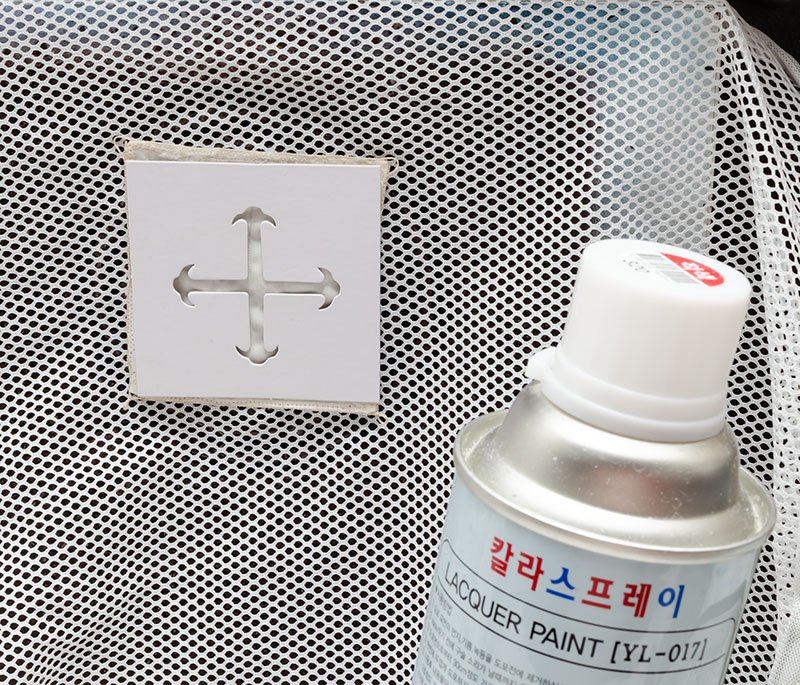
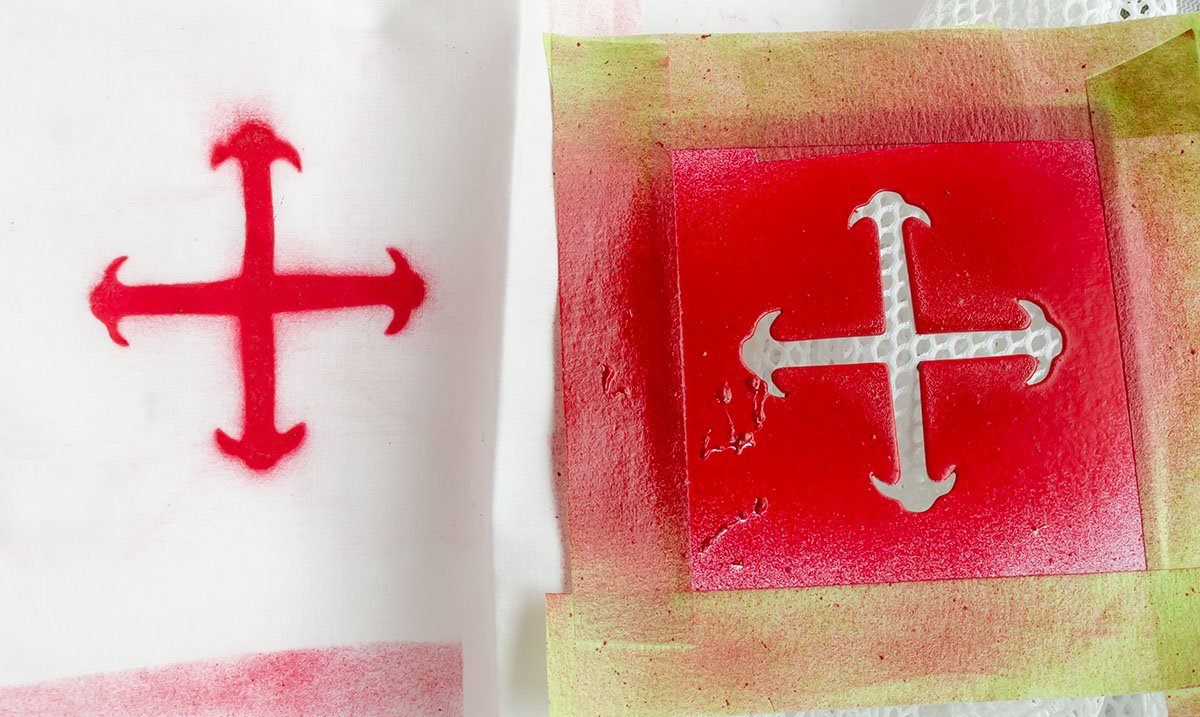
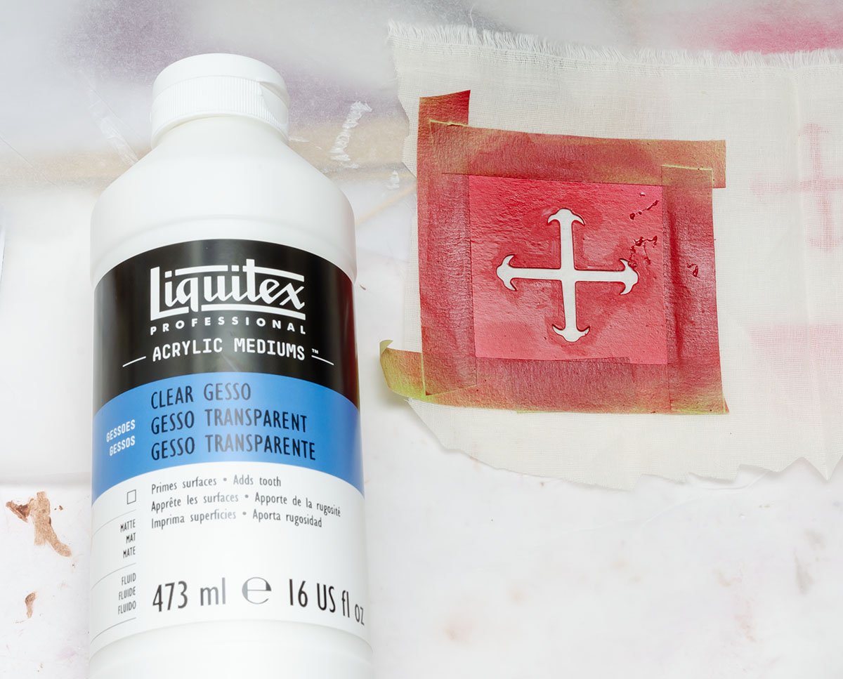
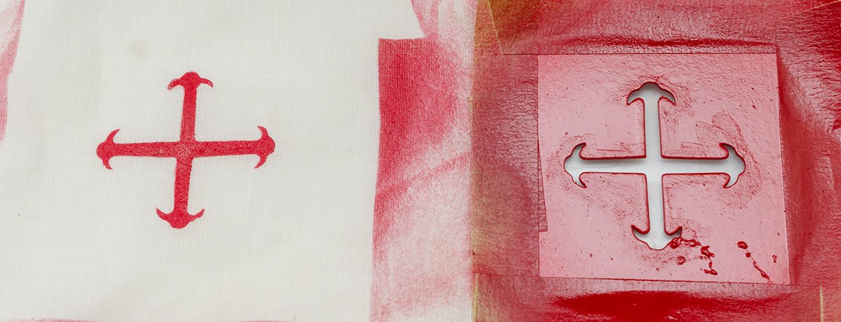
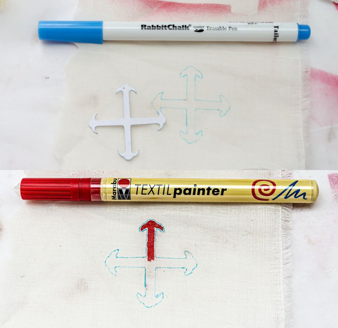
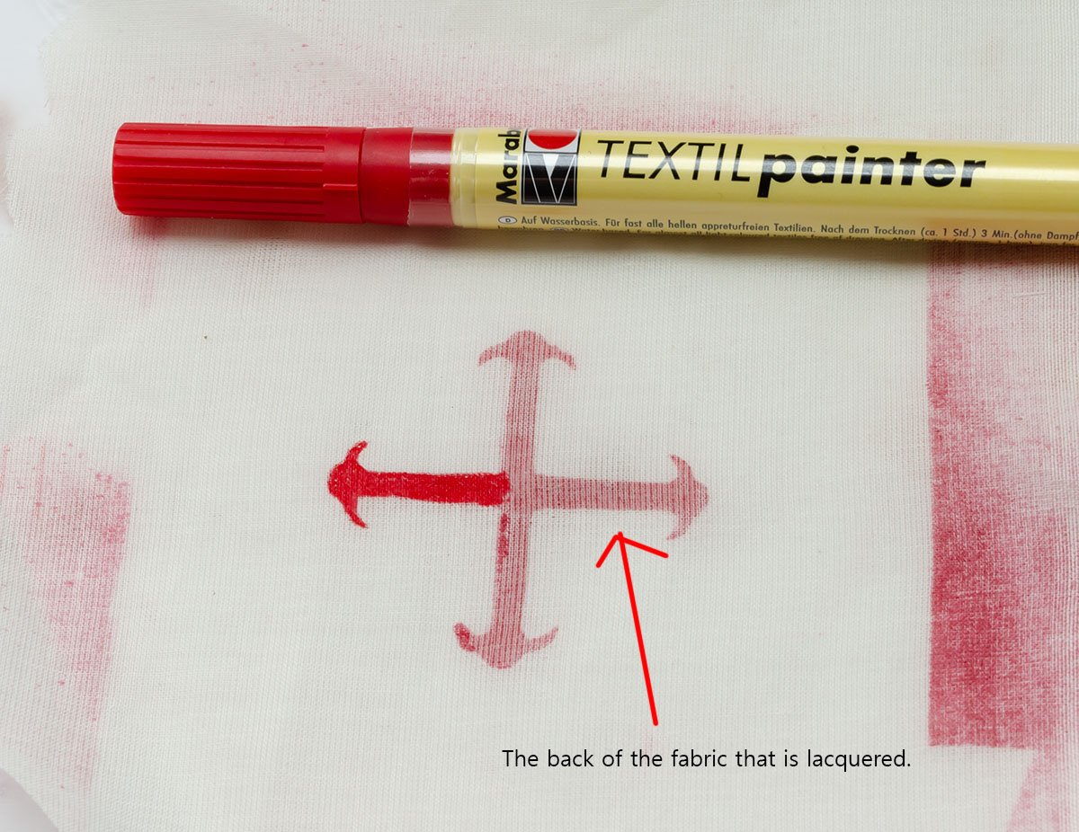
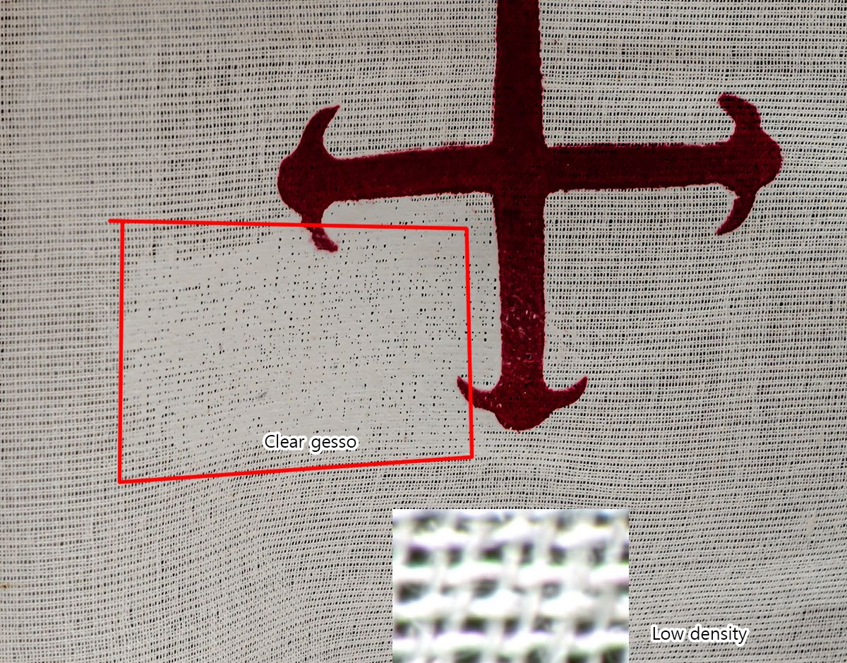
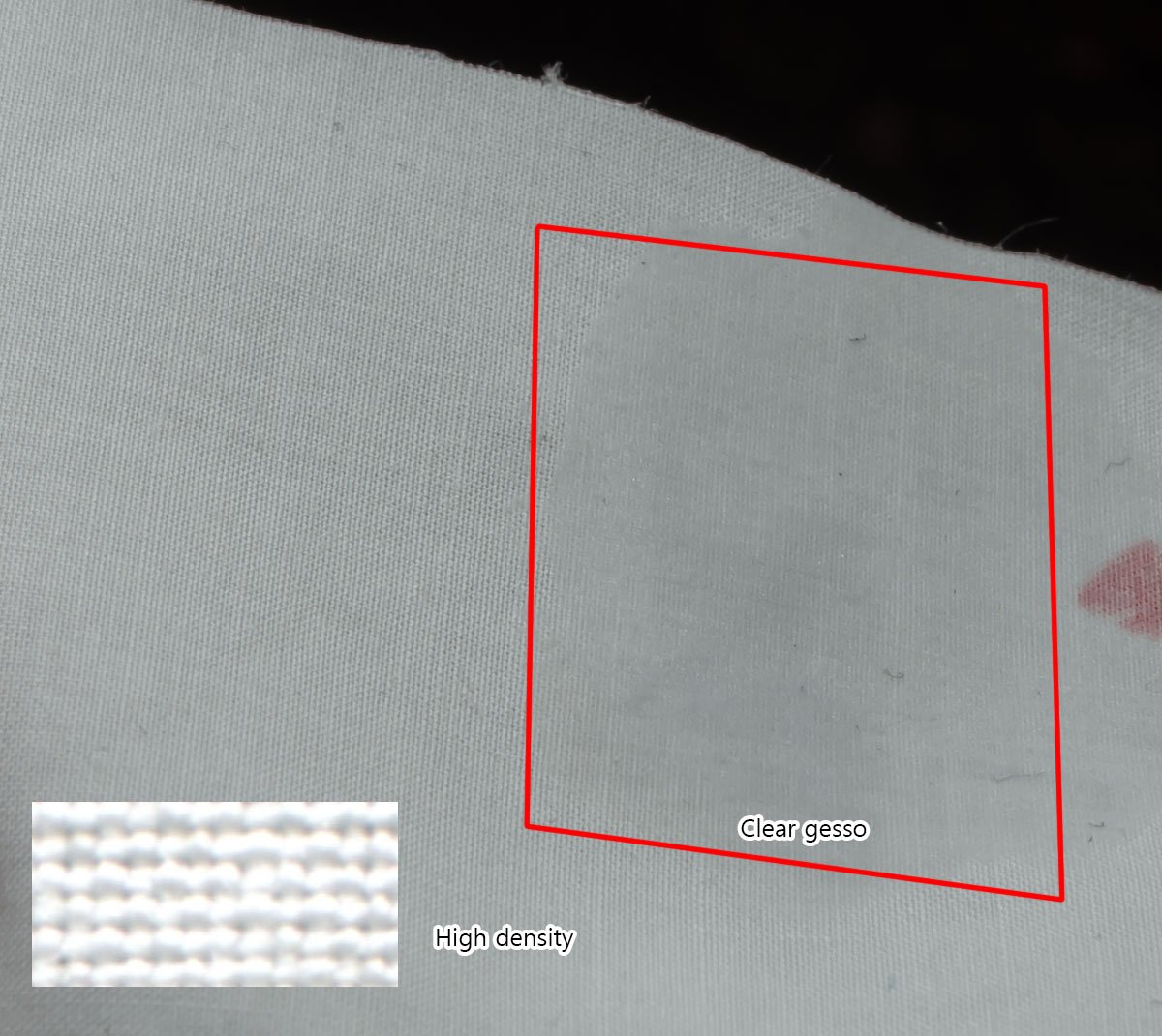
Hello, I've tested painting patterns on sails. An acrylic paint and brush were suggested in the instructions, but I preferred a simpler and more convenient method. First, I tried stancil spraying. It didn't work, unlike a plastic model. The reason is that a gap between fabric and windows doesn't stick tightly. Fabric itself is a very rough material unlike plastic parts. Therefore, I purchased a clear gesso, which is commonly used for canvas painting. It'll seal the gap like a primer. The result. Nice and clear. I also tested a traditional fabric marker pen, but it heavily depends on the painter's drawing skills. 😂 There are alternative ways to use the fabric marker. I use it to fill the back of the lacquer spray. Because fabric is flexible and it's hard to set up the stancil on both sides equally, I'll finish the back with the marker pen simply. It doesn't require drawing skills. If you plan to cover whole sail with the gesso for canvas, you should test it first. At least it isn't good idea to apply the gesso partially.
-
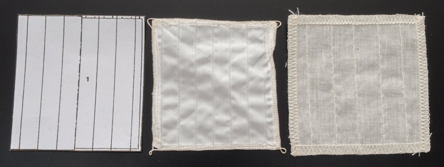
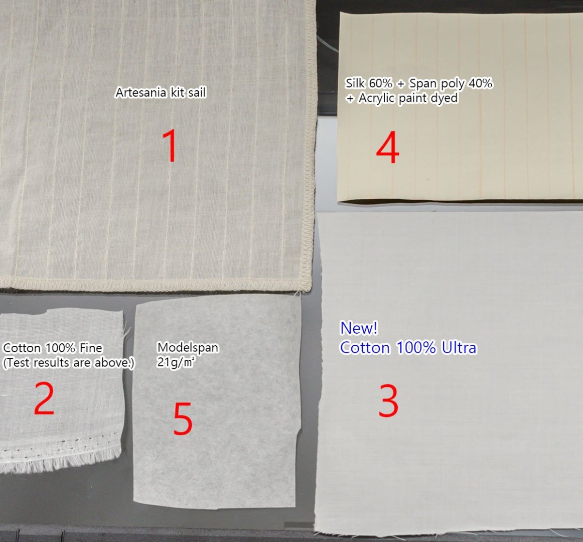
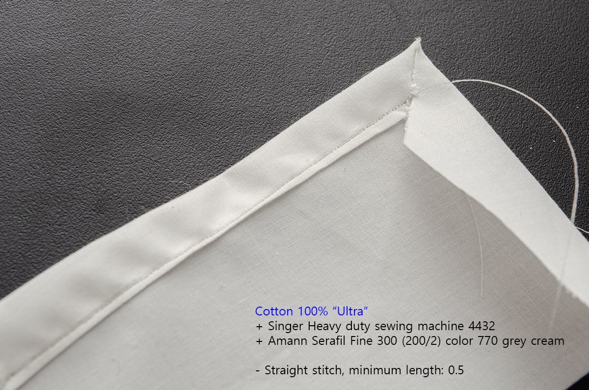
I'm upgrading the kit sails to DIY sails. All my studies and questions can be read here. As you see, my final choice is durable sewed sails.
-
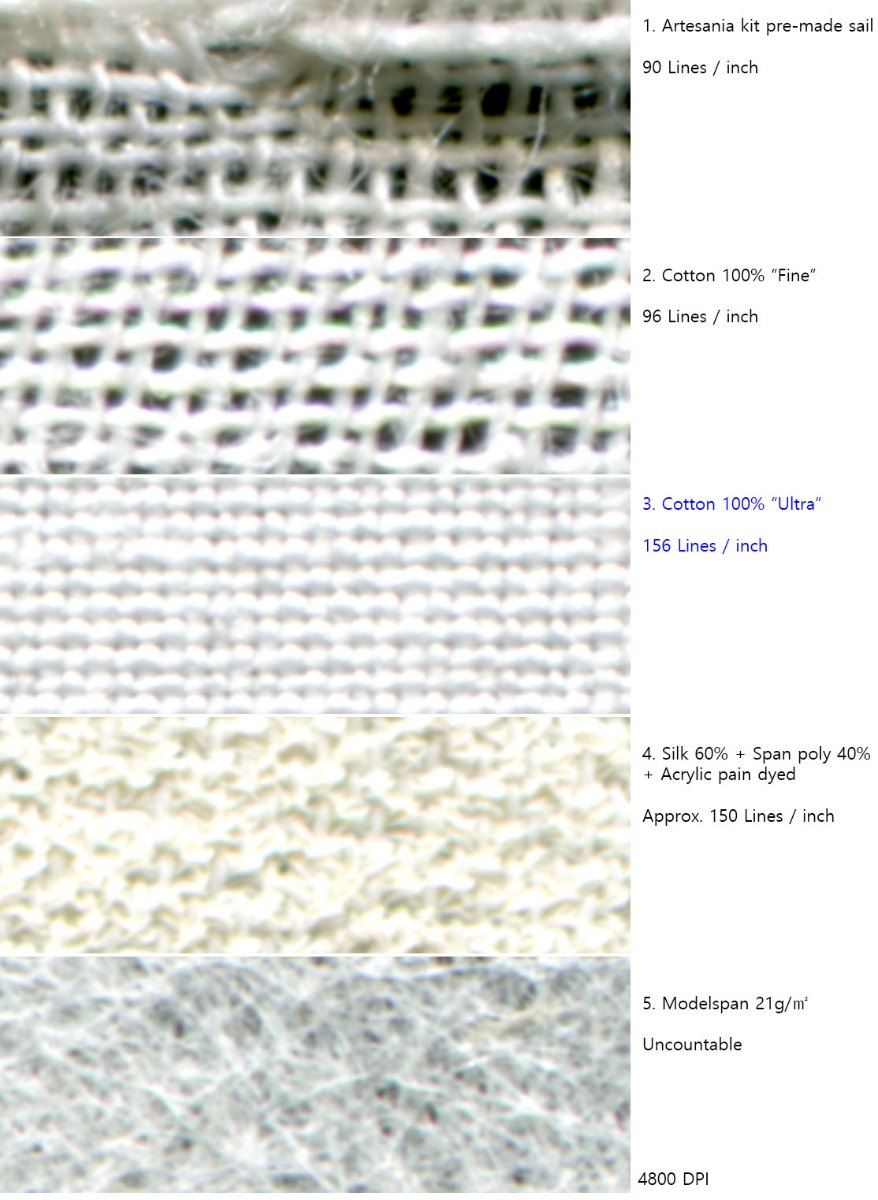
I found another fabric I purchased at a local store long ago. In general, the spec of this cotton fabric is one of the top in my country, although the other cotton fabrics I tested before had the same spec. Because different countries use different scales, especially on cloth area, I can't simply convert the spec of the fabric to TC. (I don't know how to calculate it.) Isn't it interesting?

-
Thank you so much, Dziadeczek! It looks very nice and so realistic! And it seems to not be too challenging. I ordered the thinnest English beading needle, which is size 15, or 0.25mm in width. I'll definitely try the technique on the next ship. Allan, I purchased fabric with a TC count of over 2000 at Amazon, and it wasn't really that delicate. It is very hard to find such extremely fine fabric...
-
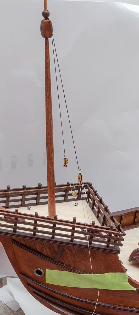
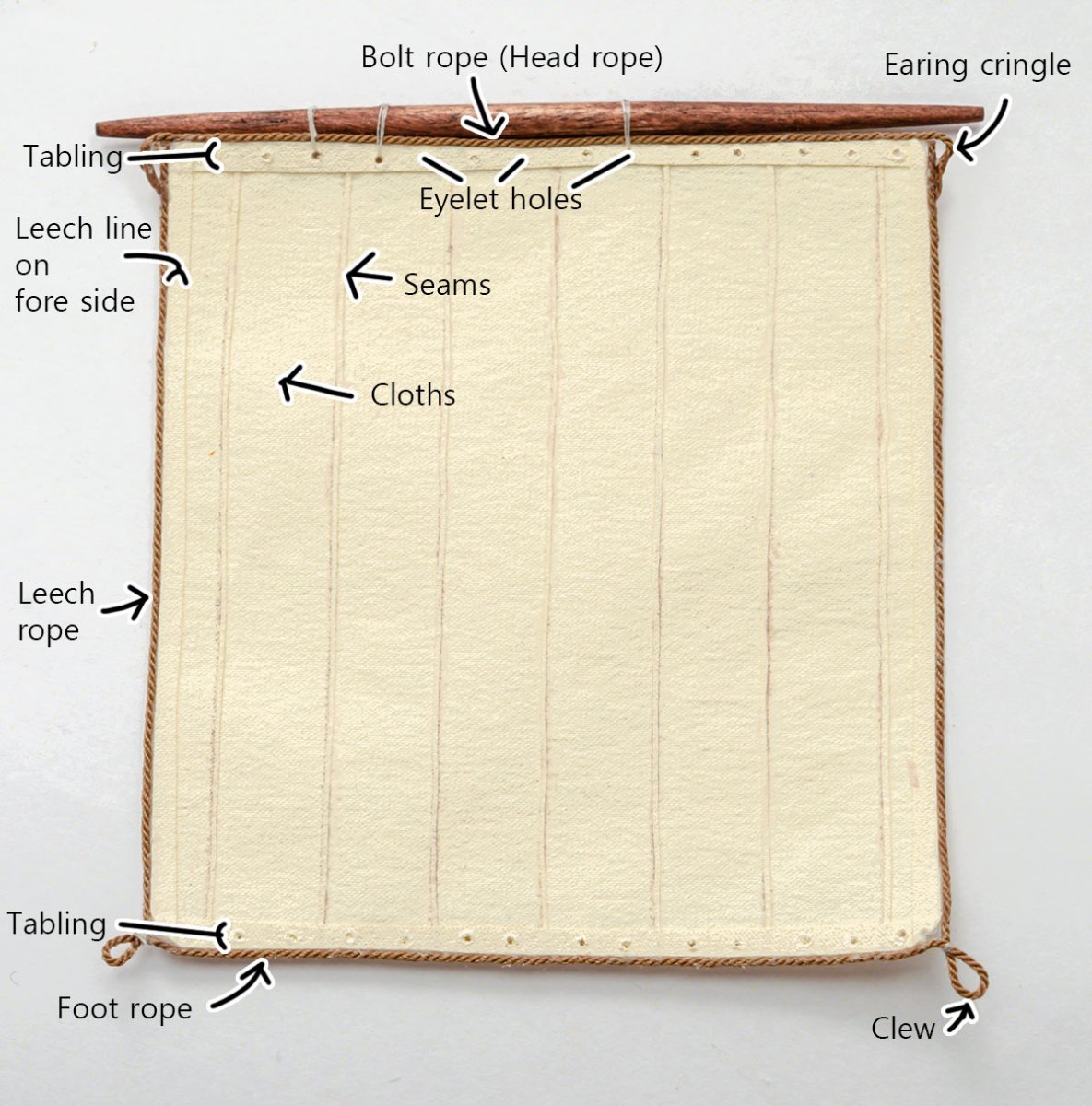
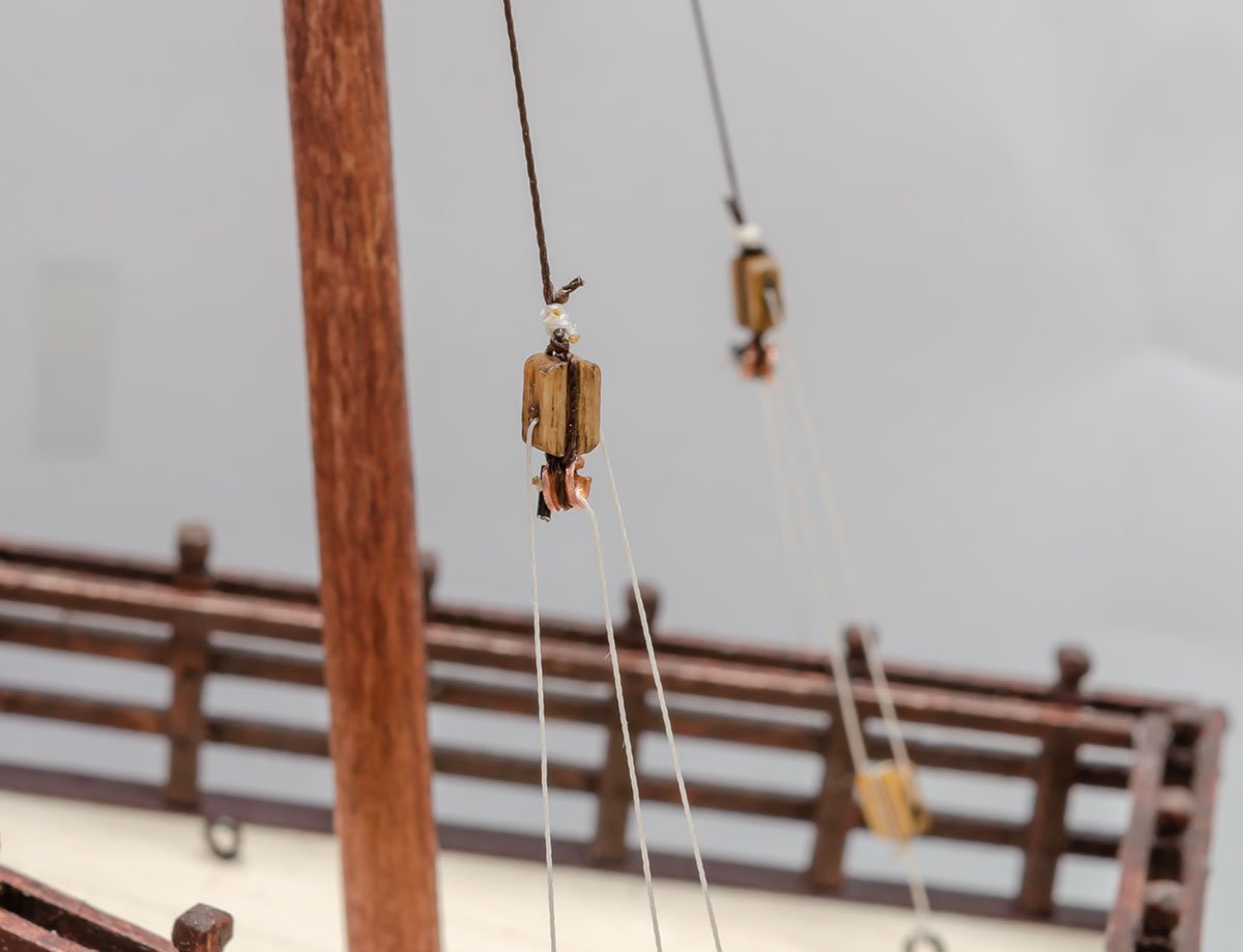
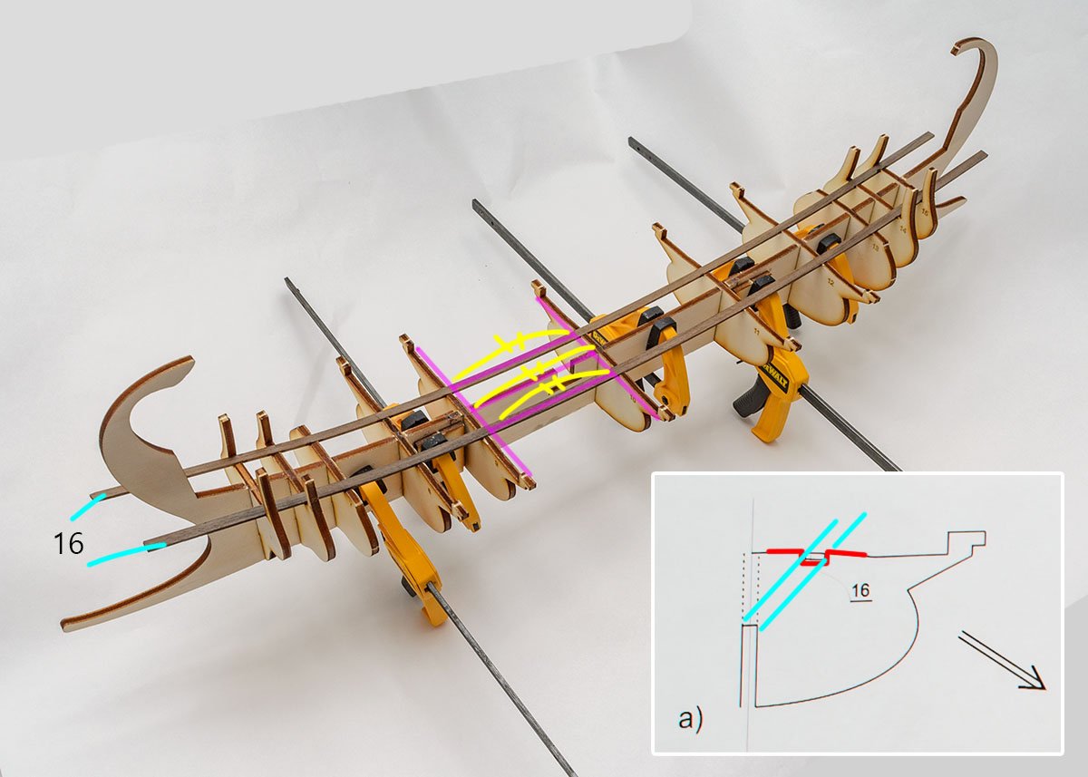
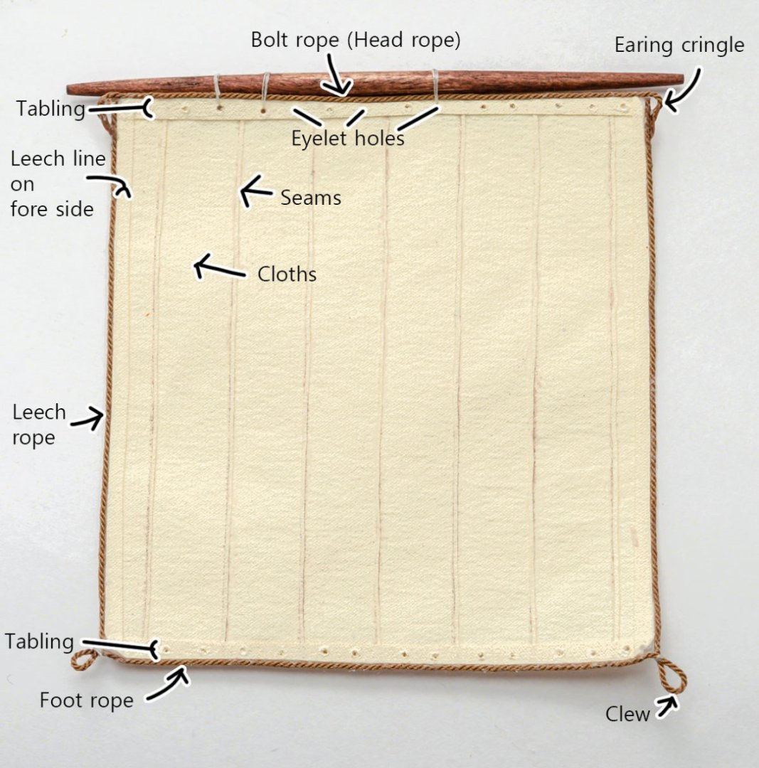
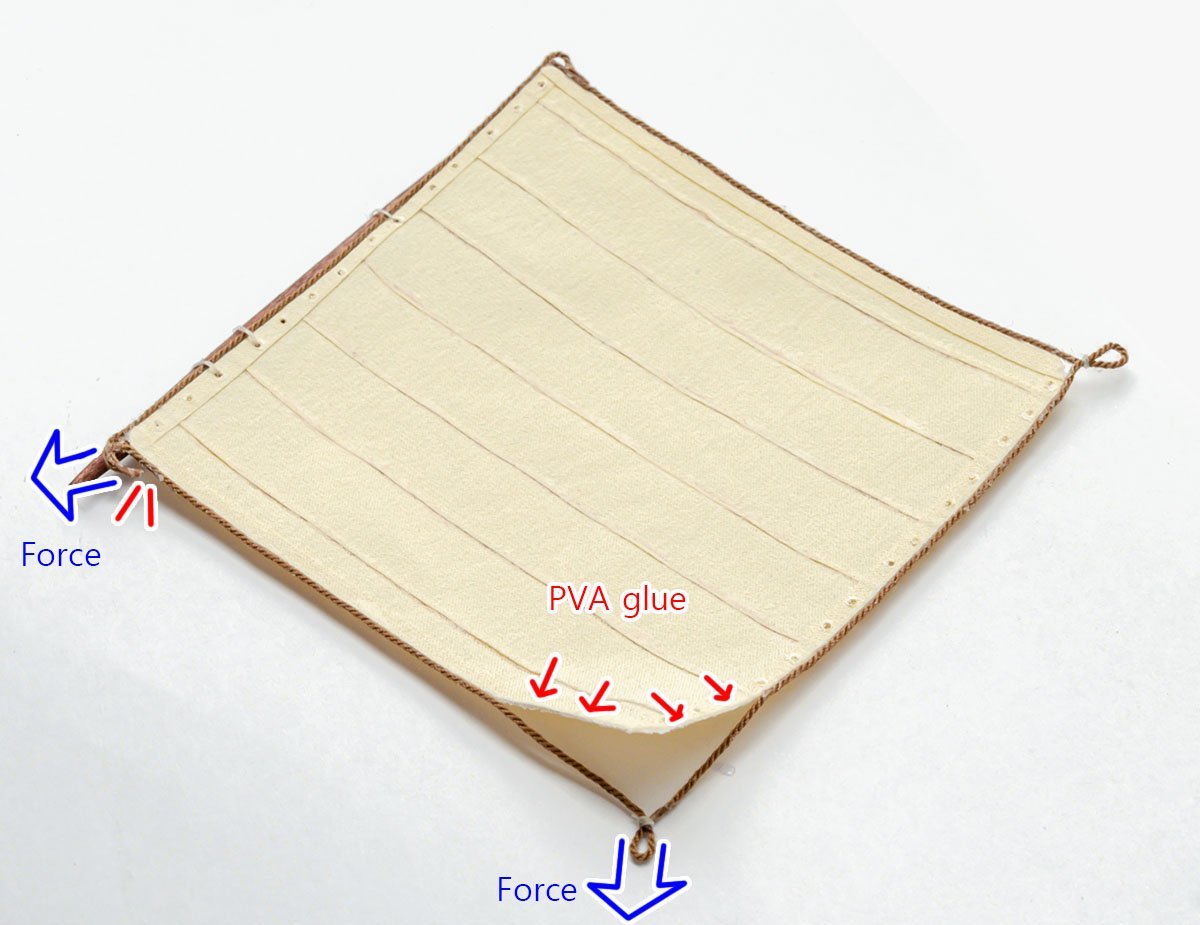
Hello, I have a question about ropes around sails. The picture shows a spritsail of the Santa Maria. I made the sail with silk fabric, so it is super thin and all the parts, such as seams and tablings, are glued by PVA bond. My major reference book is the Xavier Pastor's book, so I added leech, foot, and bolt ropes as the book illustrated. I also referred to this video to glue the ropes. All the sails are scale-accurated (The width of seams and tablings are 0.45mm and 2.29mm), so I have no space for sewing between the rope and the sail. As I was worried, the ropes were weak. If children accidentally pull the sail, I may spend hours repairing the finished model. I don't want to use CA glue because of the poly threads. I said that I have no space for sewing the threads, and the glued ropes are hardened so I can't sew them well. In this case, how do you reinforce the adhesion? Could you recommend stronger glues or a better way to hang the ropes?
-
Making a Silk-fabric(?) Sail
modeller_masa replied to modeller_masa's topic in Masting, rigging and sails
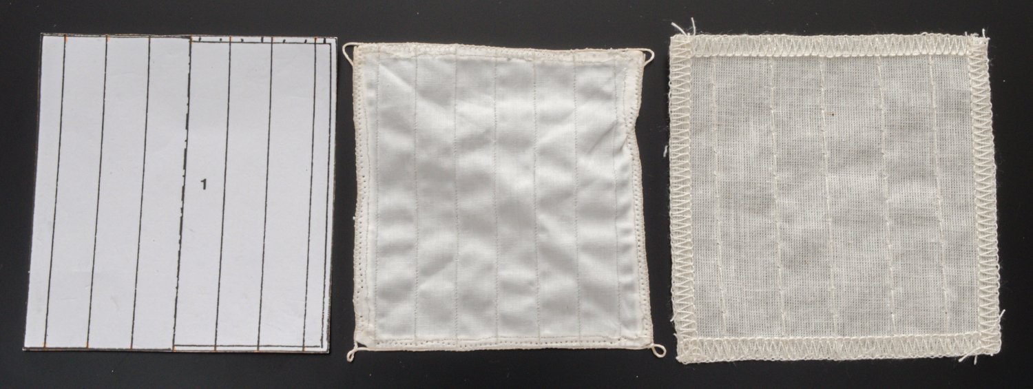
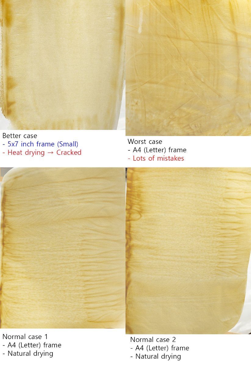
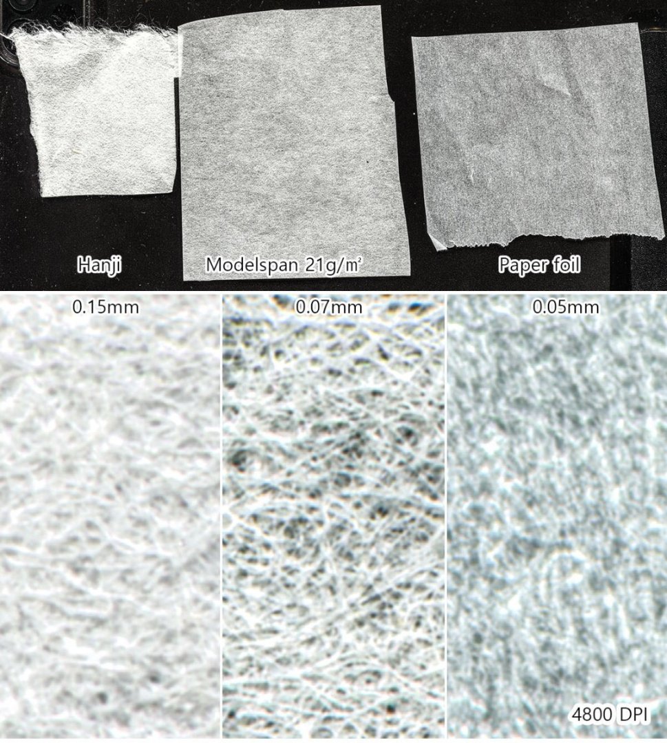
LOL... I already have the silkspan tissue... I discovered that the silkspan is known by many different names in different countries. The silkspan in Korea is called "Korean paper" (pronounced as "Han-ji"), and it is very popular for traditional painting and wallpaper. In China, the same paper is called 'Xuan paper' (pronounced as xuān-zhǐ, and xuan is a name of a city in China) and also called 'Japanese paper' in Japan (pronounced as ko-zo-ga-mi, and ko-zo is a name of wood.) The traditional papers have relatively rough and visible fibers in general, so I bought specially produced silkspan tissue made in Germany for scale models, which wefalck recommended. ( Link : https://www.modulor.de/en/modelspan-tissue-white.html ) The left is a Hanji, which is very popular in Korea. Unfortunately, the paper shows lots of visible 'branch fibers', so it isn't good to express sails. The right is a paper foil, which is silicon-coated tissue for kitchen. I don't think it absorbs water or solvent paint well. I'm a bit exhausted from building the "silk fabric" sails, so I'll update a new test with "the real silkspan" when I build the next ship.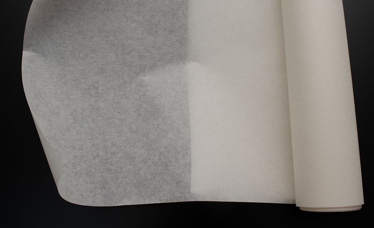
-
Making a Silk-fabric(?) Sail
modeller_masa replied to modeller_masa's topic in Masting, rigging and sails
Thanks for the information, Allan. I'll research the tissue paper again. -
Making a Silk-fabric(?) Sail
modeller_masa replied to modeller_masa's topic in Masting, rigging and sails
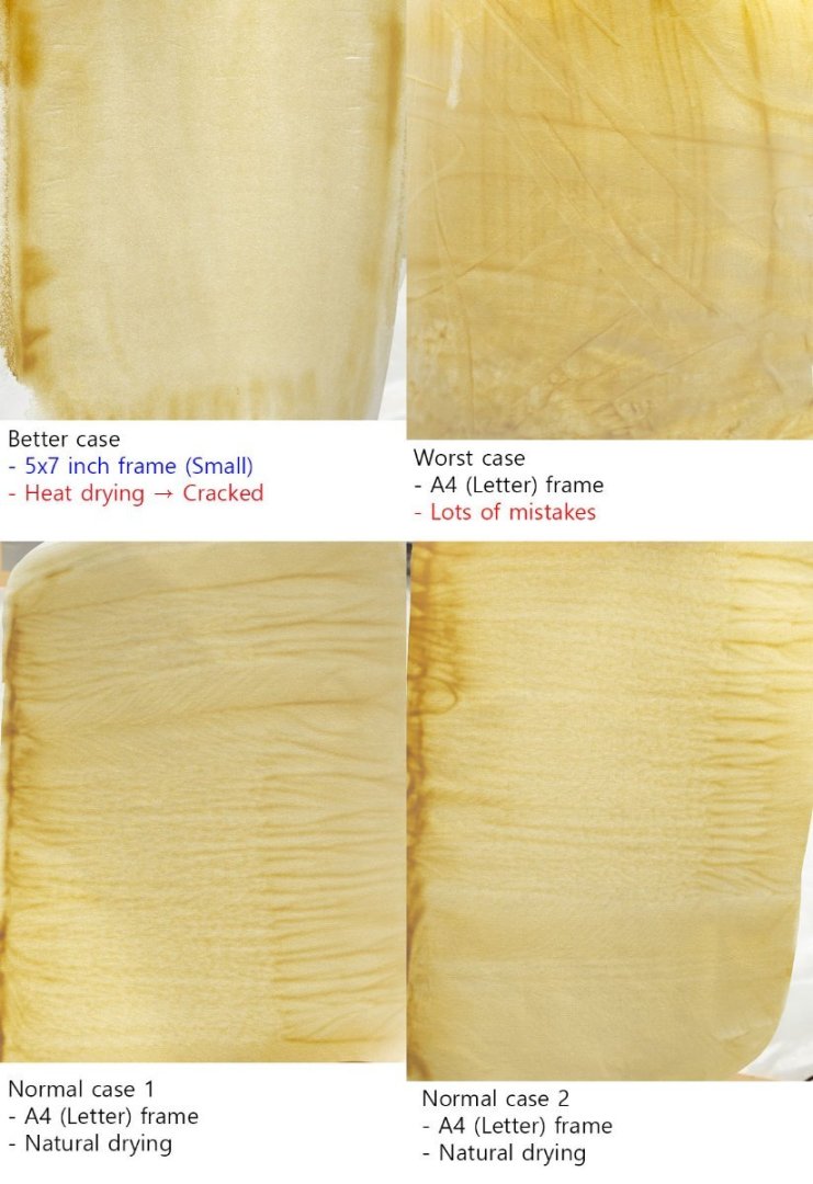
Update : I added a heat curing progress after drying. I followed a tip for dyeing silk with water based paints. I couldn't be satisfied with 'big' frames. Managing color uniformity without a heater is so difficult. I started to think the furled sail is much better. I guess that one of the secret receipts is tension. I'll reinforce the frame like a silkscreen painting. I'll also try acrylic paint spray for less water and even painting.