HOLIDAY DONATION DRIVE - SUPPORT MSW - DO YOUR PART TO KEEP THIS GREAT FORUM GOING! (Only 68 donations so far out of 49,000 members - Can we at least get 100? C'mon guys!)
×


Egilman
-
Posts
4,377 -
Joined
-
Last visited
Content Type
Profiles
Forums
Gallery
Events
Everything posted by Egilman
-
 Between the oil barrel on the cross bucks and the corner brother, just turn the tires sideways.....
- 189 replies
-
- 10
-

-

-
That's my one complaint about Rhino Kevin, knowledgeable support, when you can find it is priceless.... What Richard is offering here is priceless IMHO..... You will have some support from McNeel but it's like all such support, they are the software writers, everything is simple to them..... as far as interoperability between softwares, I use file export for all transitions between packages. my preferred file type is .obj... Ancient I know but the most stable.... And all three export that file type.... SW has good support, good forums, good training and more tuts all over the net than you can imagine, they run from very low grade to education grade and that is only the free ones.... The paid ones are similar but a step up in quality..... Heck, they are teaching SW in high schools and community colleges.... As far as usability for ship modeling, SW does have a few issues I've ran into.... Especially on intersecting compound curves when you need them to stich together, it can get to the point where it says the surfaces are stitched but in reality they are not... The common resolution/workaround is to extend the surfaces past each other and trim them off at the intersection, but that doesn't work reliably... (the gaps remain) You then have to go searching through the model to find the gaps and close them individually.... It's why I haven't finished the Predator in SW... Rhino I believe has the ability to show you where the gaps in your solid model are and point them out for fixing.... SW has nowhere near the number and complexity of issues F360 has though... And it does crash once every blue moon but it's recovery routine is very very good.... Rhino, as far as it goes, I would defer to those who know cause I plain flat don't know anything... (the long and the short of it) I judge the order of issue level between the three is thus... (based upon my limited experience) Worst to best... Fusion 360... Solidworks... Rhino..... I'm already at the point where I will not bother with F360 any further, heck it couldn't handle a basic chine hull which was easily done in SW, on an identical machine, I've already shown that.... And from what I have been reading a basic chine hull built from curves is childsplay in Rhino.... I want to see what it does with the superstructure of the predator... Once I get my feet under me in Rhino, I won't be looking back.... And there I run into my main problem with it, good accurate info... I will keep up on SW as another tool in my box for stuff it is very good at but my hard modeling for model making will be done in Rhino....
-
Thank you for this, I just finished up the essentials course and it explained a few thing which is good, but not anywhere near enough... I was just going to go looking for the method to get images into the view screens, this is right on time.... He covered this a little bit, and definitely explained about using as few curve point as possible to have an optimized surface, in fact he drove the point home.... Curve analysis, he touched on this but didn't go into detail, I'll need more info on the technique.... That's one of the first tips he made and the need is easily seen.... Besides all the other software I've use uses the cntl/alt/shift keys for screen movements, so this is making the Rhino screen view controls conform to the controls I already am used to... And makes the arrow keys much more useable.... (which they aren't in the other softwares) Thanks for the tips Richard, they are timely and right on point.... Invaluable really...
-
Good to see you here brother, I'm going to do this come hell or huge water.... {chuckle} This is the future of modeling I think.... Welcome aboard....
-
It has all that and more HG, if there was a good way to learn it, (a decent set of serious tuts available) I would have been using it a long time ago... It natively opens in 4 view mode but that's just one click away from becoming a one screen show... And the interface is fully configurable... It feels a lot like, (I hate to say this) like the Autocad user interface.... If you've been doing cad for a long time it will be like old home week.... If your into rendering it uses the VRay rendering engine which is also top of the line and it offers a full range of export options.... So what you do is fully transportable to any other software you might like... Some of the stuff it does and no other software is developable surfaces, flatten surfaces/objects into patterns for cutting, (paper model designers love that one) Too many to list them all... If your familiar with and like general cad software, you will like this...
-
Outside of allowing 6 weeks time, no...
-
No sweat Richard, it's all good, I suspect that coming out the other side I'll be able to figure out how to model the other hull types, they are all basically built the same way, just different in the details.... As far as videos or recorded live sessions, both get the job done, my experience is videos work better than live sessions (as long as they show all the steps) but I can work with either... That experience comes from watching too many Autodesk University web casts that feel like a waste of time wondering what I learned from my investment... I haven't given up on ADU webinars yet, but they are the last place I go to actually learn something....
-
Right now I'm sitting through a fairly boring hour of a two hour course on the basics of Rhino, it's interface and how to draw primitives... I suspect in the second hour they will get into more interesting things.... {chuckle} Nothing like starting from the beginning....
-
Kevin, it isn't the drawings just like it isn't the tools, in the case of the drawings, once they are complete they become a tool as well.... No matter how accurate the drawings are it is the information they convey that is what is important... the picture can be a bunch of scribbles without a straight line in them, but as long as the dimensions are correct, what is built will be correct if the craftsman knows how to read and interpret them.... you know this, I know this and I'm sure Richard knows it.... I'm going to prove it with a horrible bunch of drawings out of a fairly crappy BoGP.... What gets me is how many in documentation don't even know how to read what they are in charge of taking care of... Good drawings are better, true, but as long as you know how to use the datum on a drawing it's line accuracy doesn't matter... I do a set of drawings for a customer client or boss and they could generally tell me what it was by looking at the pictures, but that is about all.... (some of them could only read it out of the title block) But telling someone to just use the drawing as a template? Wow! The scale effect at the scales we normally work at is insignificant, but when you start bumping up to 1/25th of even 1/35th scales it becomes an issue... Your printing issue is probably a lack of supports for a resin printer and probably a touch of under exposure leaving the resin just a bit too soft... If there is no hint of it in the software then the slicer works from the same mesh, highly doubtful the issue is there...
-
And we have the scale factor to deal with, we are working at much much smaller sizes of parts where minor discrepancies could become a major issue in larger models, in smaller ones they are much less so....
-
I would as well, they are usually laid out on a tarp about ten meters behind the trails with only two or three of them ready to load, the rest in their shipping containers.... They were too fragile to leave laying around underfoot...
-
And those subjects really don't interest me, modeling is what I like and will be taking it straight to 3D printing.... Just looking for the easiest and fastest way to model accurately so I can scale and print....
-
Ok I just hooked up My account at Linked in and am going to run the essentials course for Rhino 7 once I get it installed.... Just getting ready.....
-
Well I just signed into art station, looks impressive.... Personally, I can do pretty much anything but realtime... that's a non-starter for me.... I've acquired the latest Rhino available short the maintenance updates 7.11 I think it is.... And I hear that Rhino 8 is in beta testing now...
-
Well I'll follow along as best I can, live online stuff may be the thing today, but it shuts a lot of people out..... The CS, (a beautiful ship btw) being a composite hull made of wood and steel wouldn't have been my first choice... Something steel with at least two screws, a steamer bow and cruiser stern.... Just my preferences.... Anything you offer Richard will be good....
-
Yes it is and yes they did brother.... Autocad is cad and is great software never said it wasn't brother.... (it's why I use it myself) I was specifically referring to Fusion 360.... Marine needs have always been different than general drawing/drafting... Can you design a ship in Autocad? yes, do you want to no.... {chuckle} Can you design a building in Autocad yes, do you want to? no Autodesk themselves make a product called Revit exactly for that... Autodesk themselves know the benefits of specialization..... My first brush with autocad came 30 plus years ago....
-
Well thank you for the validation... I didn't start out for this to be a comparison of SW & F360... But it has become just such a disparity in what they actually are they aren't even in the same class.... I personally believe that F360 trying the multiple compound curved surfaces of a Predator 108 will put it in it's grave... It can't seem to handle a simple two panel chine hull.... What I drew in an hour in SW, was next to impossible in F360 and then is locked up, you can't go any further.... And there are people that pay for that crap? (yes according to autodesk) I think since your willing to try, I'll just ditch F360, I don't have the patience I once did with things that are less than expected.... And I no longer accept beating myself up trying to make less than adequate tools work the way I want them to... I know what the tool is designed for and know how to use it so I don't have to spend my abilities and time making it do what it is supposed to be doing itself without issue... Enough... Thank you for the honesty Kevin, I know it can be painful when you have invested so much into something... (especially when someone from outside confirms your suspicions) I invested a lot into Sketchup, until it went commercial and lost a lot of what made it great..... Same with Blender, there was a movement to make it more flexible to use then they went along and at one of their congresses decided that they were aiming directly at the CGI markets and would concentrate their efforts there.... It's now a wonderful do it all tool, if you like CGI and gaming modeling... (ultra high poly videos or reasonably high poly game models) It's not worth much for anything real world... The work flow is the same, the model should be the same once it goes thru the workflow, SW will do it and I'm sure Rhino will as well... Thanks for tuning in and your commentary....
-
She is definitely an ALL-American bird.... Difficult paint job, well done brother...
-
Post war, if you study all the post war developments, you will find that for a period, that socket mount designed at Spandau was used by all nations as a quick efficient way to mount weapons up to any medium calibre.... They didn't change for ten years.... eventually as armor increased and the need for more and more powerful guns came into being, the carriage mount model became standard using horizontally mounted elevation mechanism so they could get the optical aiming devices closer to LOS which made them more accurate... Even at the start of WWII you will still see some designs using it....
- 47 replies
-
- 11
-
-
I think that given our backgrounds and experiences over decades have driven this more than anything else... we are constantly re-thinking things in pursuit of scale accuracy and how to get there.... Sometimes to our own hindrance.... {chuckle}
-
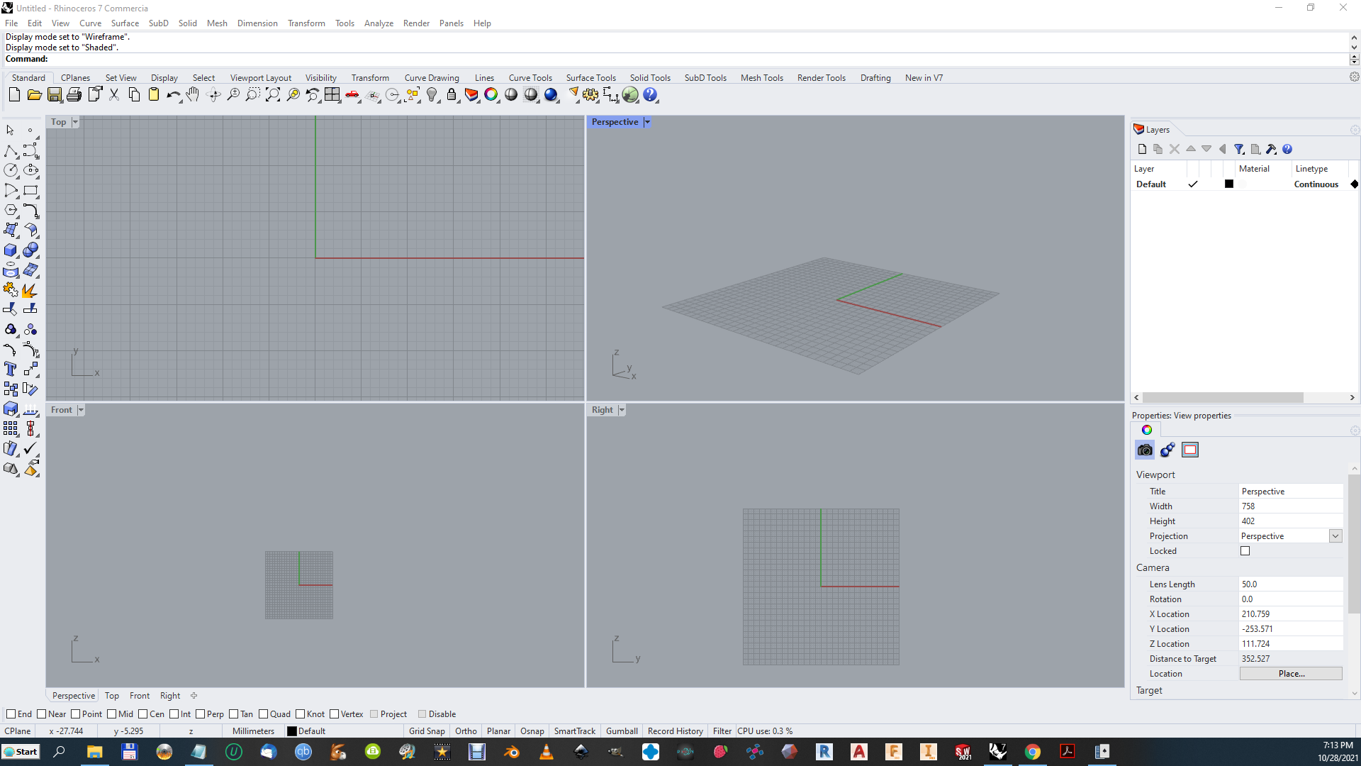
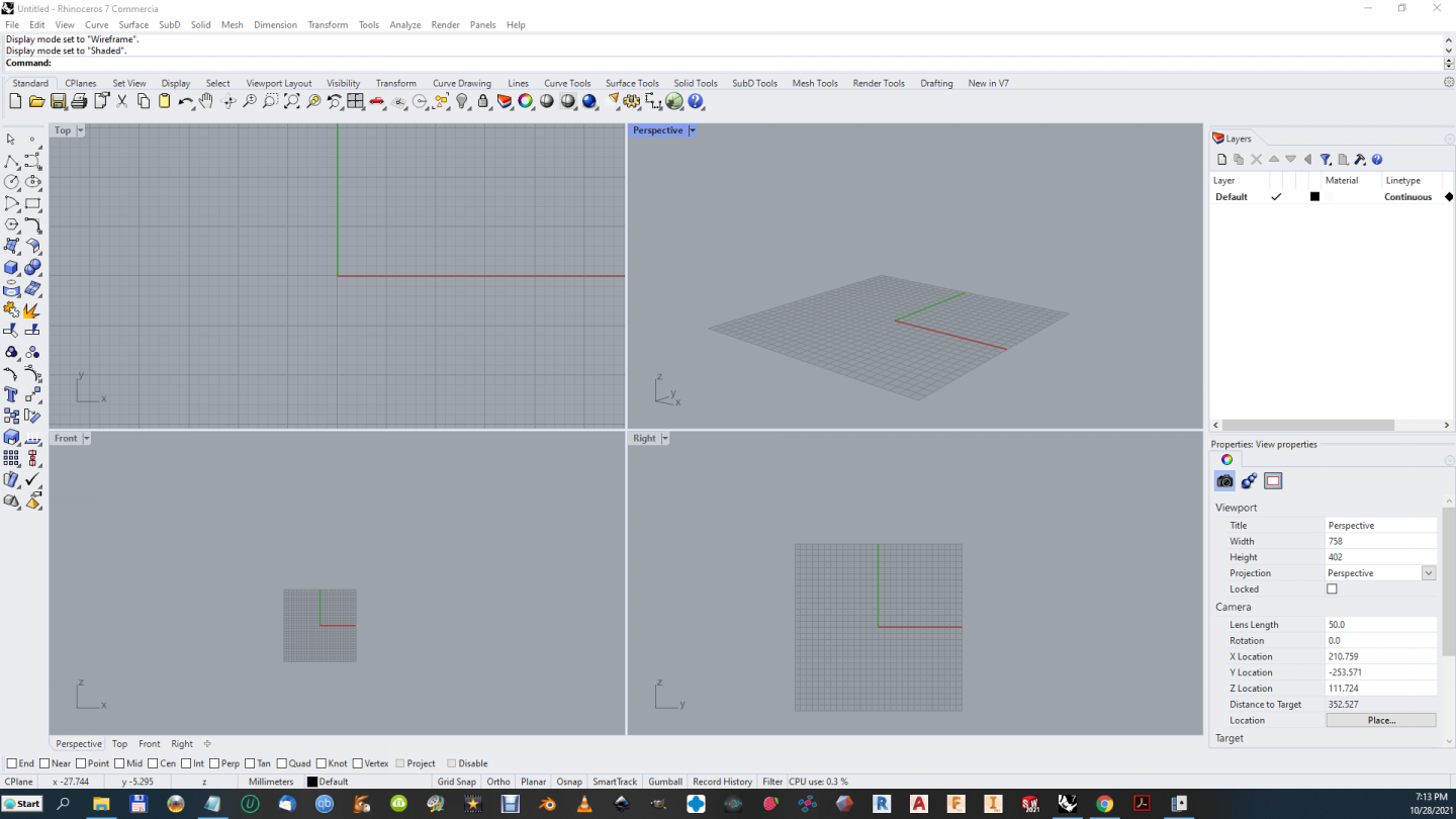
Richard, I have access to Rhino, You make it I will come.... I've yet to find a decent tut on it yet though and if you write one it will be the first.... And yes, Marine modeling/design has been using Rhino and a version of Dassault's proprietary system for decades to model ship hulls... They are the go to's of the ship design world.... What Autocad is to engineering and structures, Rhino is to Marine Design... Many people could use it most don't have the resources to pay for it... So yes, a heartfelt and sincere statement, you build it, (rhino tutorial) I will come... Right now SW from Dassault just plain works for solid modeling it's reliable and simple to learn, Fusion 360 has issues IMHO..... Good for simple stuff a bear when you get into anything larger or compound curvy... Very capable but a mountain to climb and not reliable in it's operations... works in some cases not in others and the unbelievable part is it does this on the Same Geometry one day to the next... Seems like it works when it wants to.... The direct comparison to SW shows that it is overly complicated for what it does, which I have seen all too often when the basis of the software is a cad background.... (all Inventor/Fusion products stem from Autocad as it's original base point) What I'm going to do is get the process down and repeatable for the basic hull shape solid, then let it go there... Since I've gotten this far, and the process does work, might as well as document it for what it's worth... But I'm not going to put a lot more energy into it... McNeel, Dassault and Autodesk have been competing for several decades now and each have developed their own little playground, Rhino is best at Marine Applications, Dassault is best at Aeronautical Applications, (and is pushing hard into general design) and Autodesk is trying to push into those areas but is best at BIM and mechanical/structural design....... They are all capable of doing what the others do, but each is best in the area they were originally designed to perform... It's been 30 years and that still hasn't changed....
-
Thanks Kevin, It was a ten hour marathon to get it to that point, lots of research, lots of trial and error... Right now, it won't shell, in any way I've found to try and that is the next step.... It's not ready for prime time yet... There are some errors in the time line way back at the first lofts that needs to be corrected.... So I'm going to take another shot at creating it with the experience gained, Hopefully, I'll get it back to the solid state and be able to shell it, or figure out why not.... Not completely sure of how I got to this point yet... The path of discovery continues... Not going to say I'm the first to do it this way, but I'll tell you what, there are no mentions of modeling an existing hull, (as opposed to simple building a generic hull) this way in F360 I've been able to find on the net nor in AD's forums.... Their tut's are all just an example of what they think "Could" be done.... Every one actually modeling hulls in F360 are going down the cad route rather than the much faster solid modeling route... The one thing I am going to do is comment on the non-helpful warnings they offer when F360 thinks you did something wrong... It's gets very old very quickly when all they tell you is to re-draw your sketch or re-model your model for every single issue... Cryptic does not build confidence in the product..... {chuckle} The feel of it is like your using cad to build your model or at least they have taken a cad approach to the tools they offer solid modeling... And if the input isn't perfect, it either automatically rejects it or will fail without explanation... I've also had it bail out and crash on me four different times... Seriously reminds me of the early blender days... Anyway I'm taking a break for the day, and will hit it again tomorrow... will keep everyone posted....
-
Simple solution? When you design your cannon, drill out the barrel, AND the touch off hole, making sure they intersect like on the real thing.... (create a vent for the bore of the gun, just like in real life) And then of course raise it off the build plate and angle it a bit as well....
-
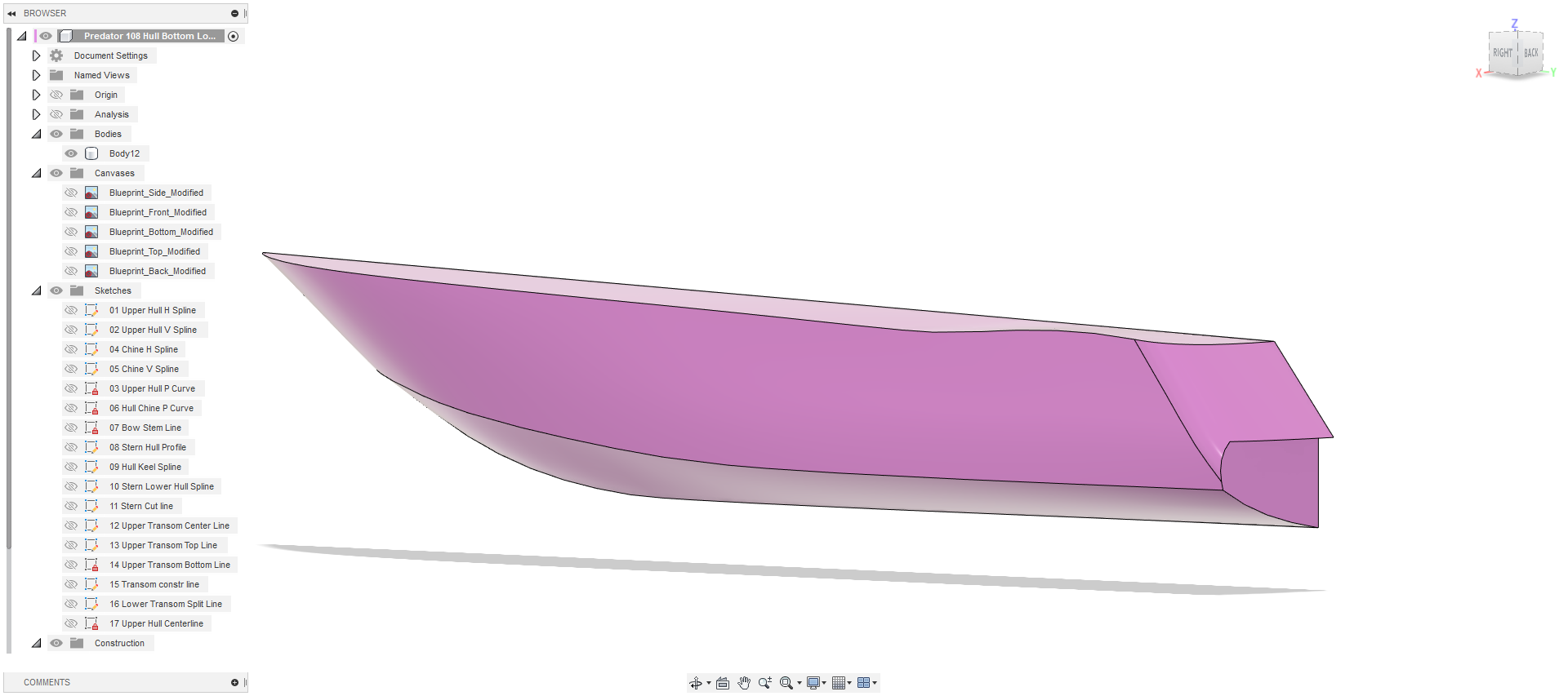
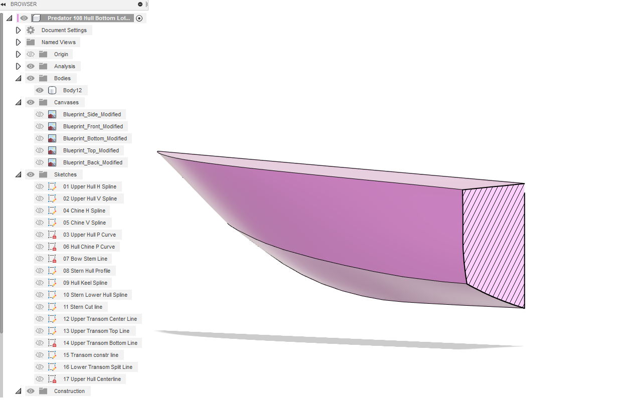
Been playing with it, I've gotten it to the point of being a solid body.... The whole thing..... One piece, that's where we want to be.... Onwards.... (although I might take a bit of a break, this last trip was kinda rough figuring out how to get this done)

-
Yes Kevin, it makes perfect sense... It's exactly how I lofted the hull side above except the bottom of the surface is the projected chine line.... What you need to do for it to work is make each of the side and top profiles one single solid spline... Then the end lines being one single solid spline as well... AND! turn on 3D sketch... So you can attach the ends with coincident relationships.... I still have to tweak the sketches a bit cause I made an error, I accidently put the stern spline on the same sketch as the chine line... It worked, but it's not the way it's supposed to be done... Where SW only uses two sketches to project the line, F360 uses three... (the projected line has to go on it's own sketch) I'm going to correct my error, then attempt the hull bottom panel loft.... After that it should be pretty straight forward... I'll post a detailed step by step when I get it finally sussed out....