Jim Cricket
-
Posts
53 -
Joined
-
Last visited
Content Type
Profiles
Forums
Gallery
Events
Everything posted by Jim Cricket
-
 Lots of nice comments, thank you all! It's a fight for time on the bench these days. Jim
 -
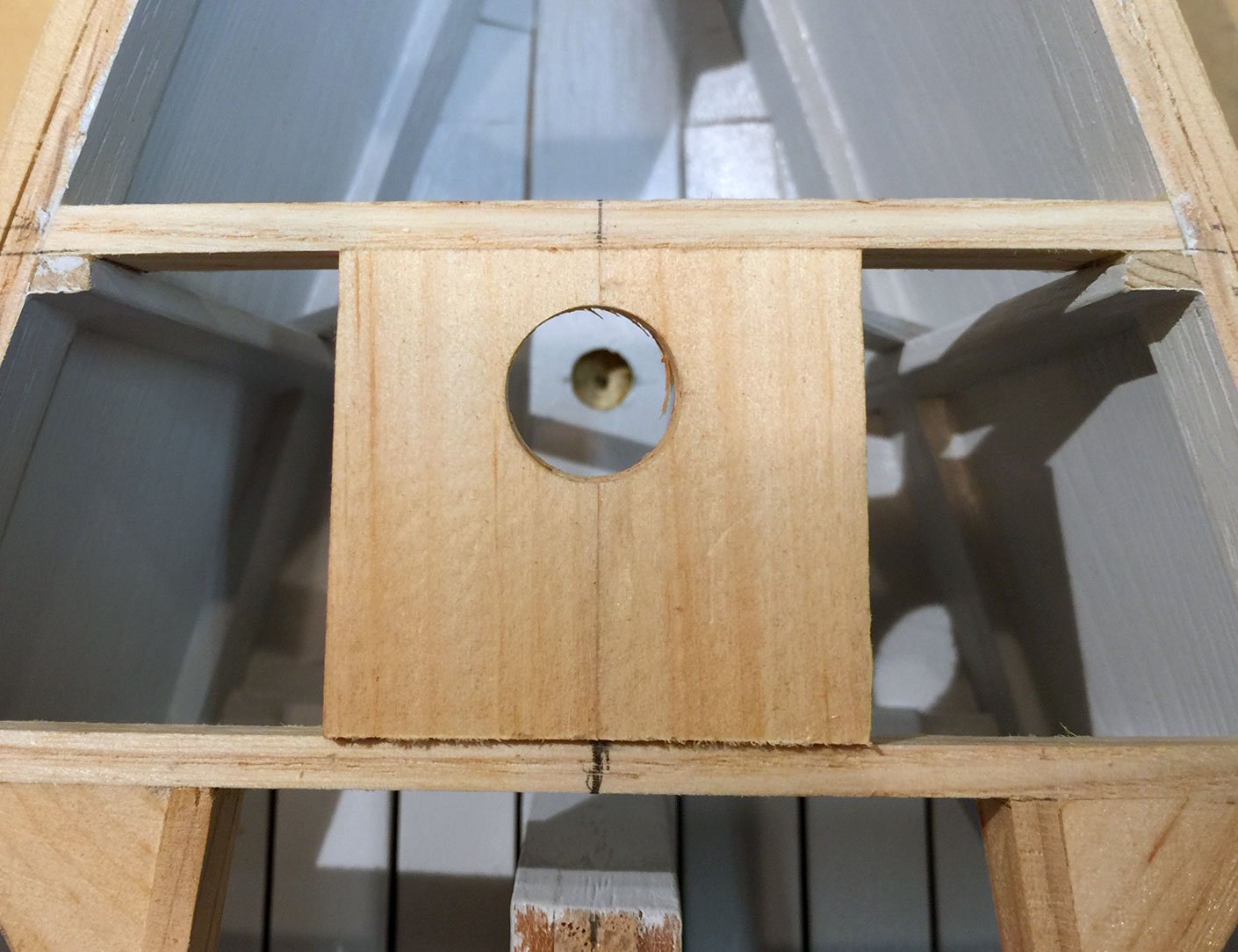
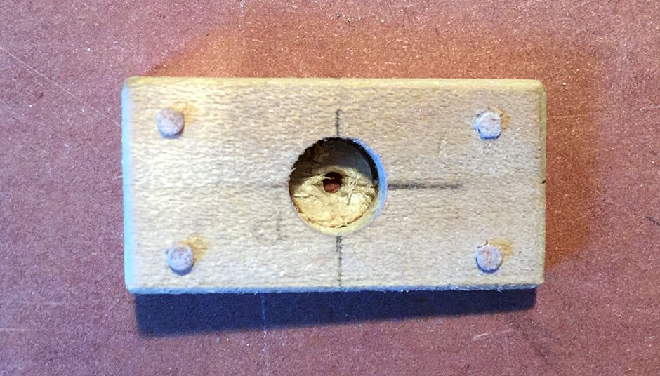
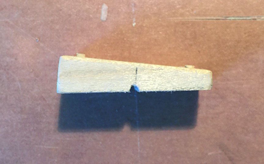
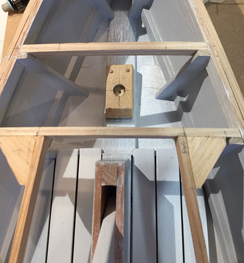
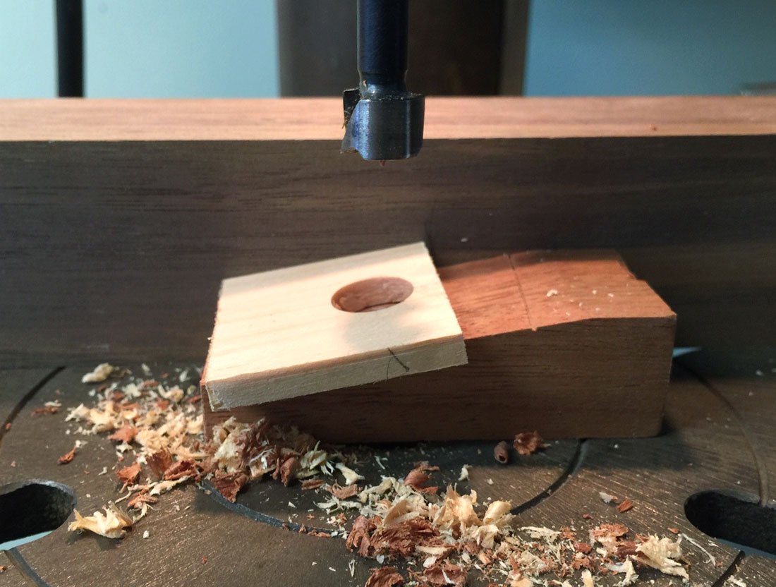
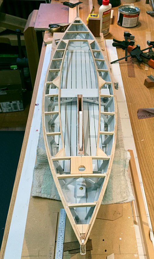
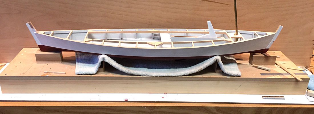
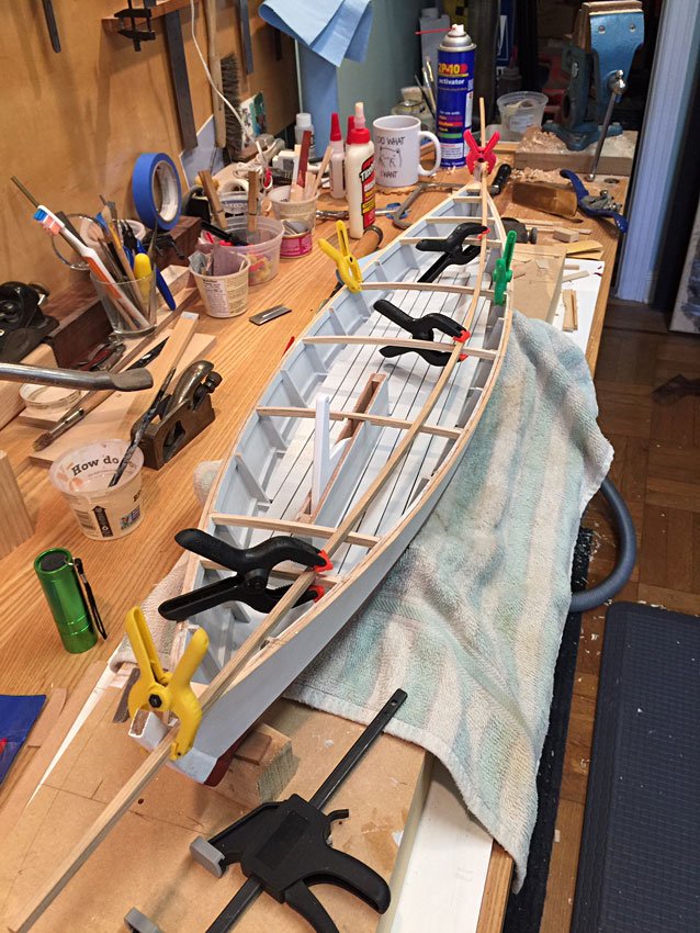
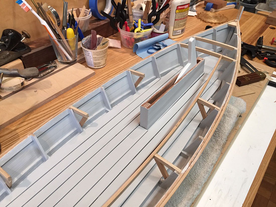
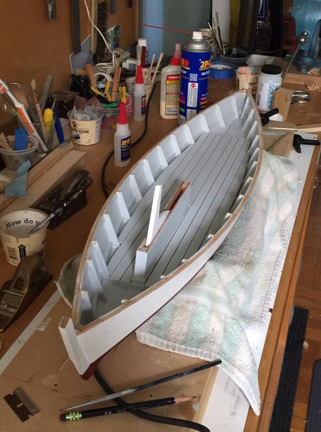
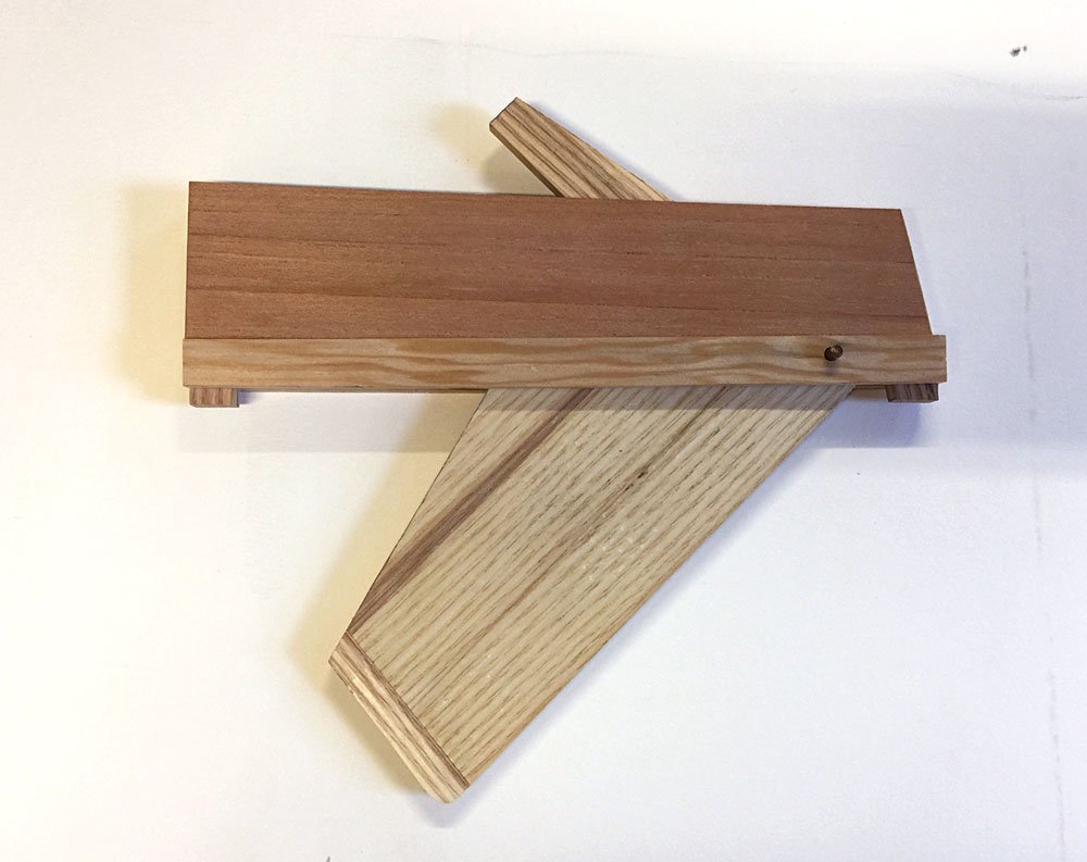
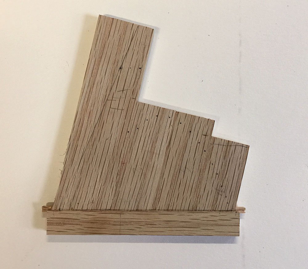
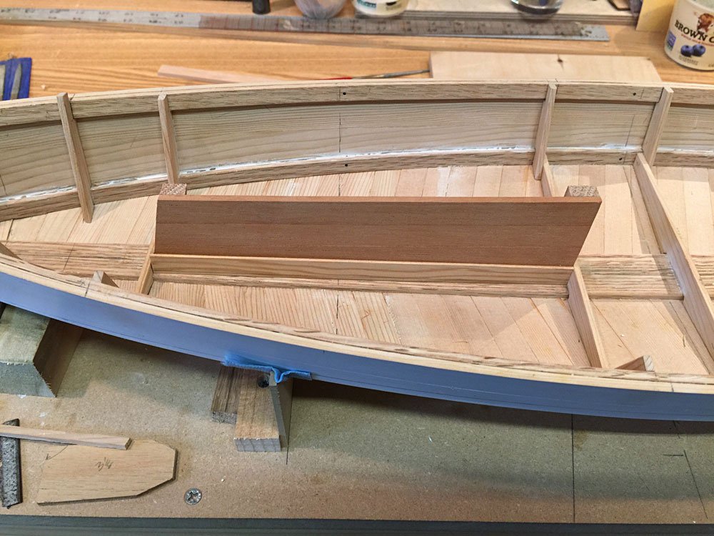
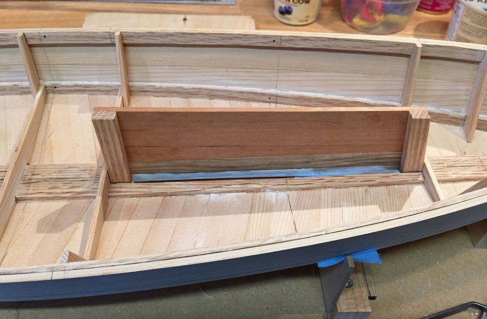
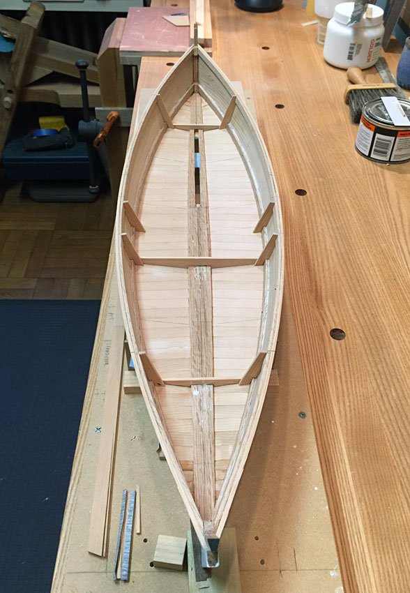
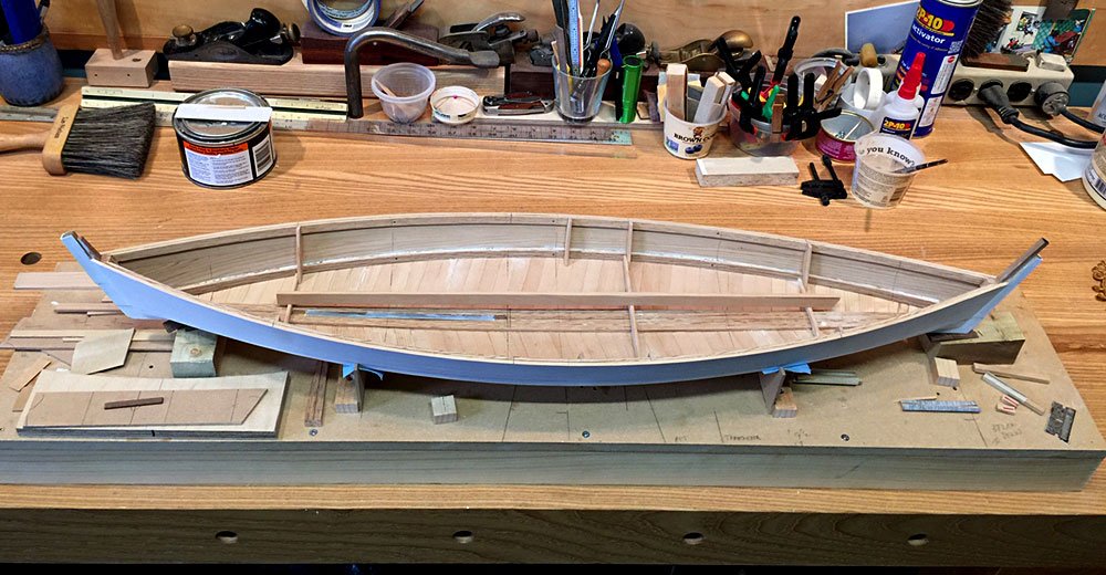
Well, I had to go back to work, so progress on the boat has nearly frozen. I did manage to finish the deck framing today. I made a mast step from poplar. It is wedge shaped, with the mast perpendicular to the raking top face of the step. To drill the step correctly, I made a similar wedge to jack up the step to the correct angle, and bored for the mast tenon on the drill press. The table tilts, but it’s easier on a small scale to just cut the wedge. I simulated the bolts that fasten the step to keelson, with some tooth picks, glued into little holes in the top of the step. You’ll never see it, but I also cut limbers from the center of the tenon mortise out to the edges to drain water from under the mast. In the pic below, the step is as yet unsanded. It looks better in the boat! The partner was bored out on a similar wedge. I made it a little oversize, and I’ll either drill an exact hole down through the finished deck, or I’ll drill that oversize as well and leather it, or wedge it. Not sure yet which. Various corner blocks of pine were also made a fitted, and all of the diagonal bracing in the cockpit was fitted. There are braces at the mast, under the washboards, and under the thwart to brace the centerboard trunk. These and the step were all primed and painted, so I believe we are ready for decking! That's it for now. Thanks for looking!

- 44 replies
-
- 11
-

-
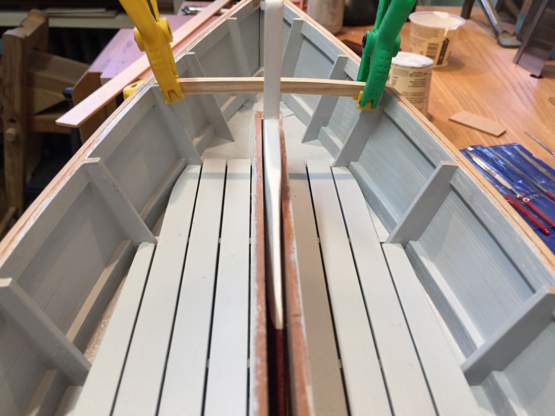
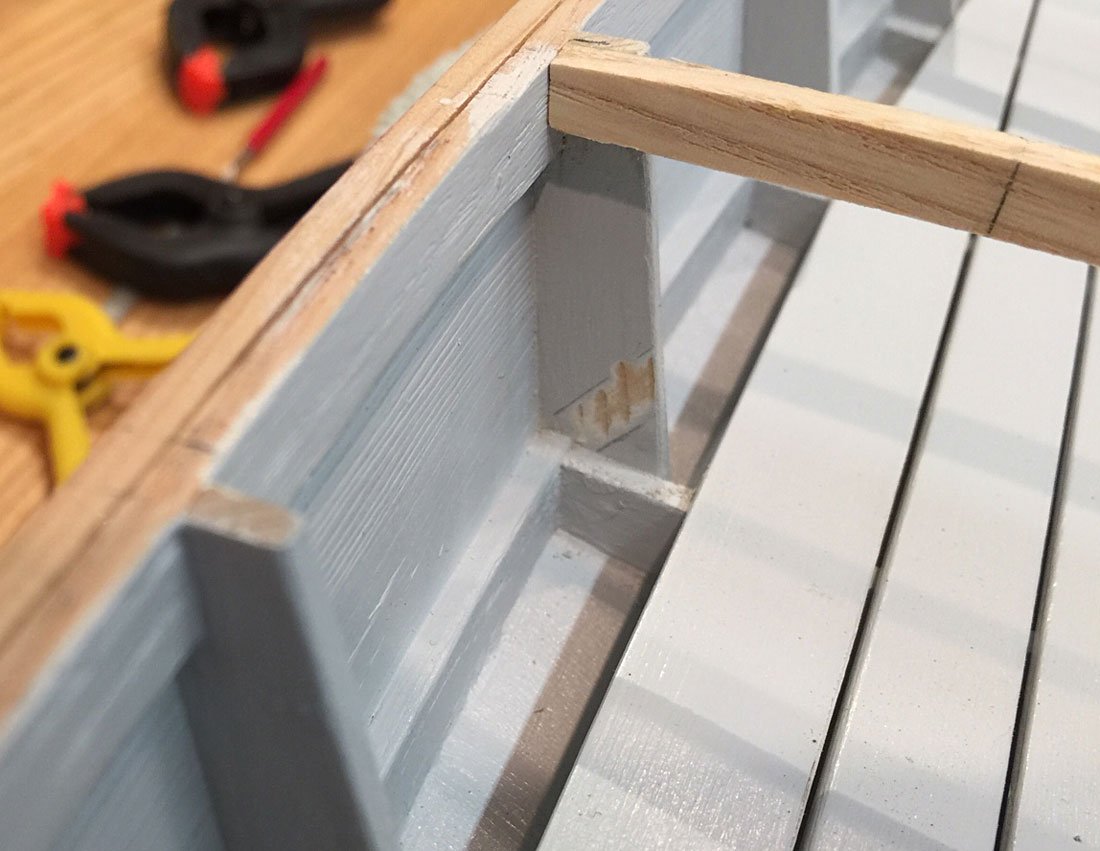
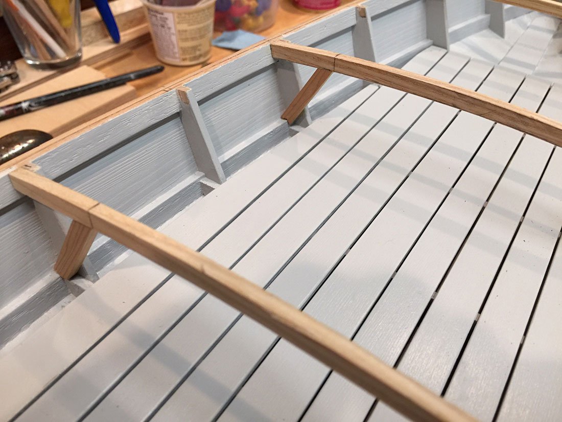
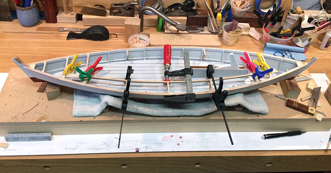
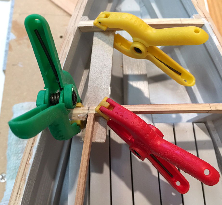
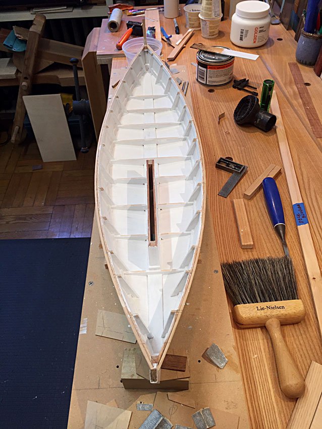
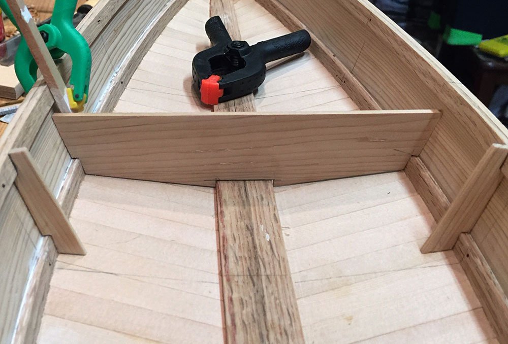
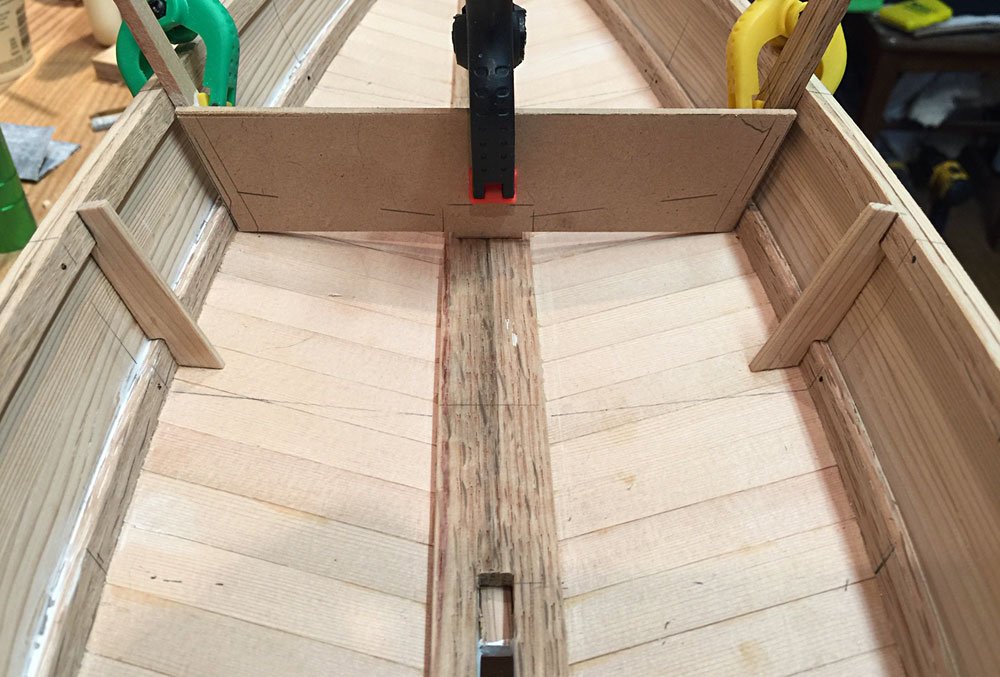
Deck Framing- I thought I would post my progress on the deck framing. I’m not done with it yet, but it’s moving along well. One thing that has to be done which I forgot about until now, is to fabricate and install the mast step! Before the forward deck framing is complete, I’ll have to stop and do that fussy little thing. But for now, I need to see some cosmetic progress, at least. I approach the deck framing similarly to the side and floor framing, with an oversize piece fitted to the sheer first, and then the top and bottom camber marked out and cut. I used the deck curve template/sander again to mark the camber, just pinching it to the raw frame by hand and marking it out, which worked well. The completed beam was the glued to the frame heads. My approach for fitting the short, partial washboard framing (side decks in sharpie parlance) is a little unorthodox, and would be wasteful of timber in a full size boat. I made and glued in an entire athwartship beam at 3 locations (where the angled deck bracing occurs), then sprung in a batten to lay out the cockpit opening curve, marked for the cuts, and fitted the angle braces. This assured that my inboard heights remained true, and that the beams would remain square to the hull. Also, I had to sand a little paint off of the side frames for good bonding before gluing in the braces. After the braces were glued in, I cut the beams at the marked location and correct angle. Chapelle shows a plumb cut on the frame ends, but I like a little outward sloping angle to the finished coaming. That angle requires a wider piece of timber for the coaming to be cut out of, but it’s usually worth it, in my experience with actual boats. Once the beam ends were cut, I fitted and glued in the carlins. I departed from Chapelle’s drawings again, and sprung in a continuous carlin, rather than sawing out multiple short pieces fit between the beams. I think that better assures fairness, in the long run. Doesn’t matter, once the decking is on, at any rate. Either way, there is a lot of end grain to long grain gluing, so the entire deck structure will be well braced with blocking, as Chapelle shows as well. At the extreme ends of the carlins, I fit a temporary brace to land the carlin on, and a prop underneath the beam to keep the carlin in plane. These I wrapped with scotch tape to keep the glue from sticking. I still have a bit of fitting and gluing to do, but I can’t get back to it for a day or two. Stay tuned!
-
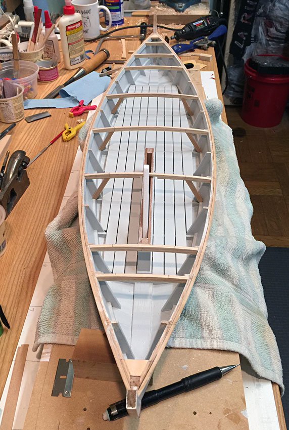
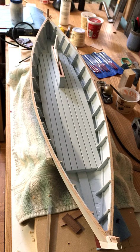
Quick post before moving on. Floorboards are painted, and installed. Deck framing is next!
- 44 replies
-
- 10
-
-
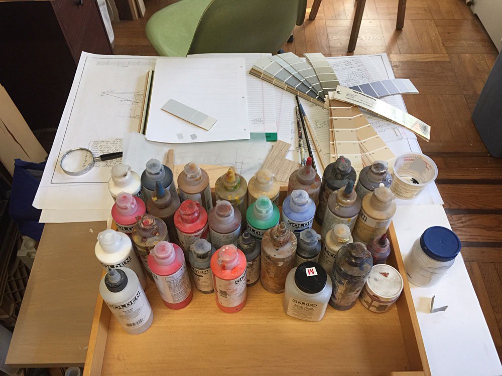
Thanks gents. Dave, I like the hue, but the value is a tad dark. With the Golden acrylic colors, I used a Pyrole Red base, then added Raw Umber, Carbon Black, Permanent Green Light, and Titanium White. Some people I've heard use Rustoleum Red Metal Primer, in a spray can. I'm trying to avoid the spray cans, if I can, though that would be easy if planned for.
-
Gary, I have only scratched the surface of your build log. But what an awesome adventure! Your weathering details are extraordinary. I have become interested in working with styrene after seeing some of your constructions, and I'll be checking back in for a much closer look. Thanks for the detailed log. Cricket
-
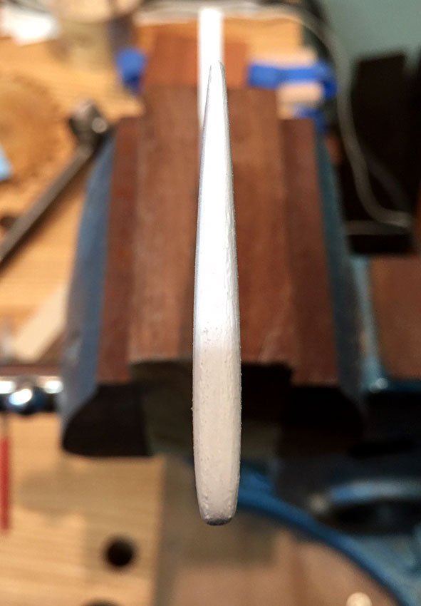
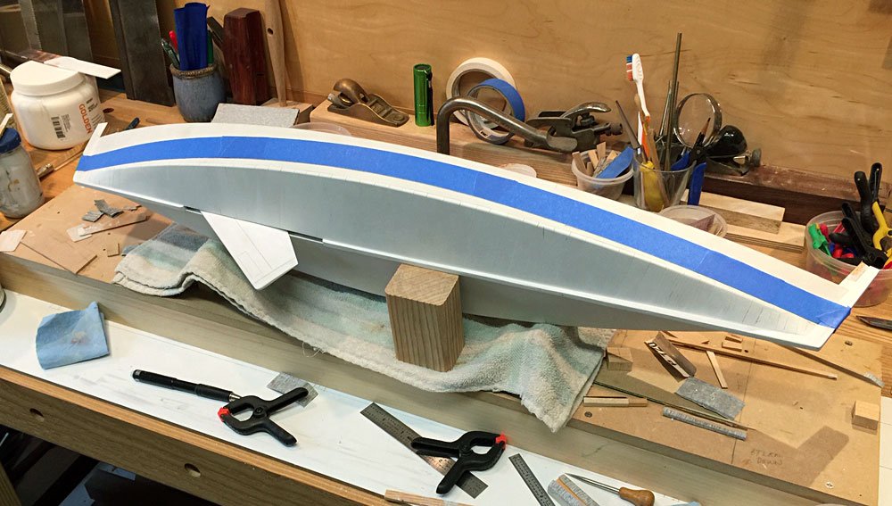
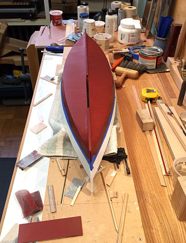
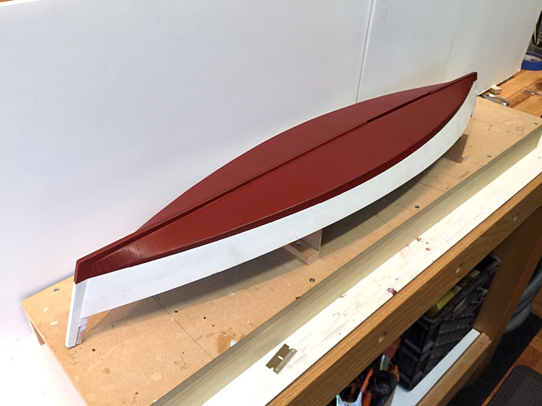
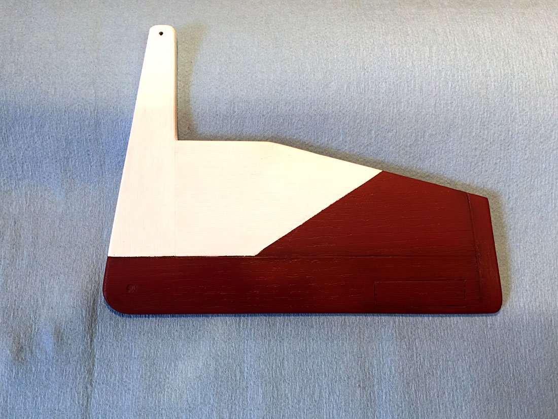
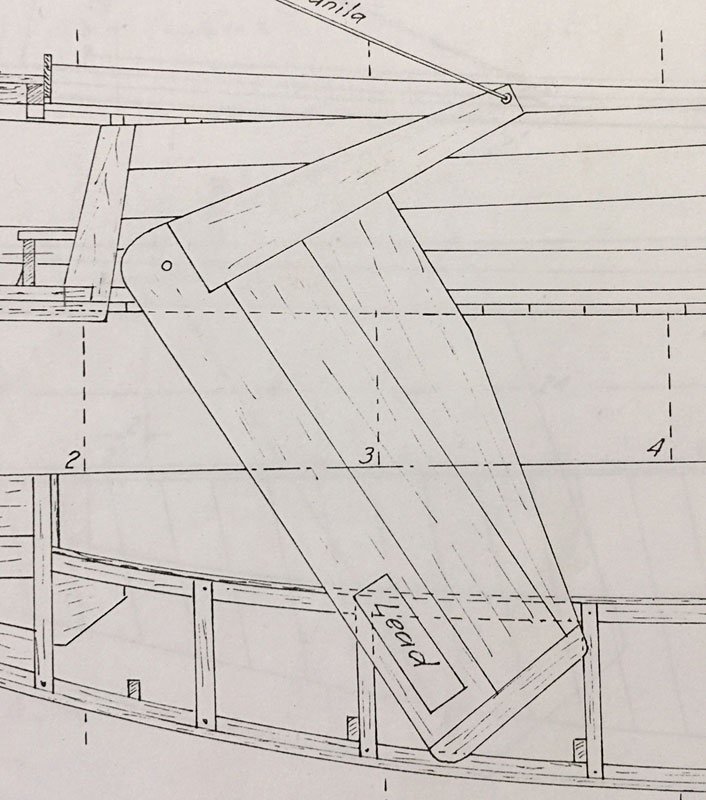
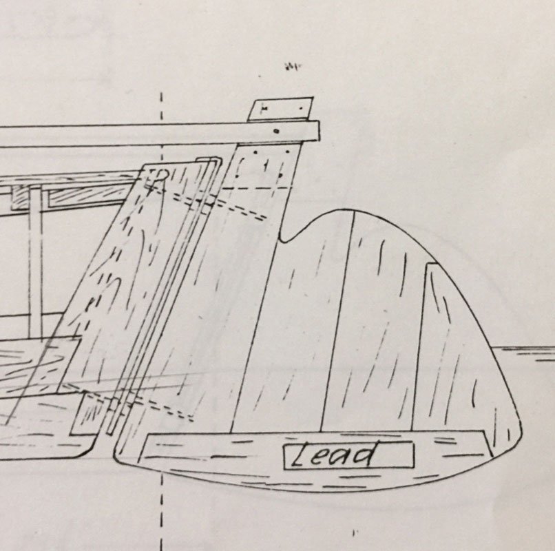
Thanks Gary! The centerboard turned out to be relatively easy to shape, and I worked a nice foil on it. Not as sharp a trailing edge as in real life, but not as fragile either, and not bad for a 90 year old boat! I wanted the construction to show up, so to that end I etched lines along the joinery, and faked in a lead insert. My intention was to let some dark paint run into the seams, to show them up. I also had to decide how far down, and how far up to show the board in the model, so I could use bottom paint below the hull, and white above the trunk. I don’t want to see the junction of the two colors in the finished model. On the hull bottom, I etched in some seams as well, hoping for a little depth and color variation in the finish. I taped off the board, and the waterline on the hull, and mixed up a deep red. The hull took four coats to cover well, over the white primer. I ended up mixing some matte medium and retarder into the acrylic, and sanded with 1000 abranet between coats. worked reasonably well. On the next model, I may experiment with milk paint, which is dead flat. I’ve used it on furniture, to good effect. I used matte varnish on the centerboard, and that knocks the sheen down well. For the seam lines, I took an ink pen, and drew the lines in black, then wiped some of it away, and painted in some dark dilute acrylic, and fiddled around with it. The effect is okay, but I think my color is darker than it should be, particularly since the bottom is in shadow. I may go back later, and lighten the red selectively with a dry brush. I’ll varnish the hull and deck at the end, after all painting is done. I’m ready to glue the floorboards in now, and then move onto the deck framing. Progress. Thanks for tuning in.
-
Hi Jim, Glad to see you back on it! I will come back when I have more time to read your log from the beginning. Nothing like having a few people working on the same, or similar, projects to get your interest piqued again. I'm trying to get a hole in my house closed up today (door repair). So this evening. Thanks for posting, Cricket
-
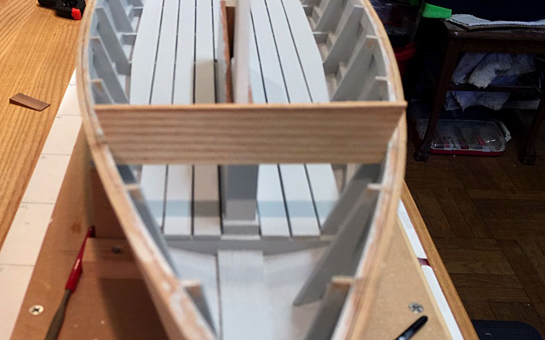
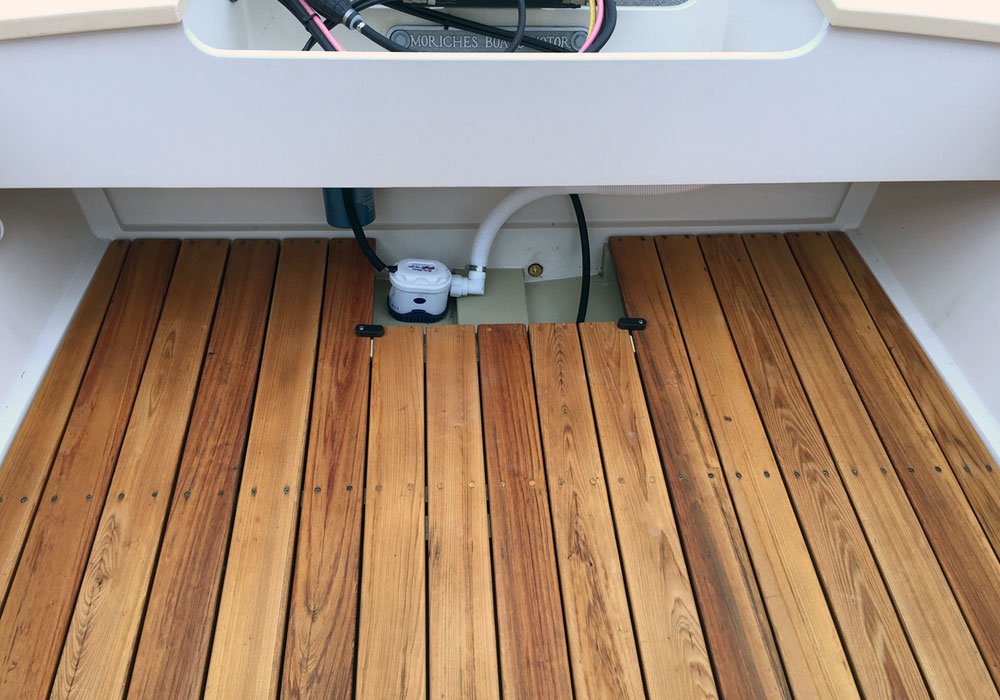
I went ahead and fitted the floorboards, before working on the centerboard. This will give me a chance to get them painted before installing. This pic shows them just sitting there, so not properly spaced and fastened down yet. In actual practice on a big boat, I would make a portion removable with buttons or whatever, to inspect the bilge easily. The pic below shows our deadrise skiff floor, with cleated center section, removable with turn buttons. Those oiled floorboards have since been painted. I'll paint the sharpie model floorboards as well, because I think the typical boats of the era would have them painted. Moving on...
- 44 replies
-
- 10
-
-
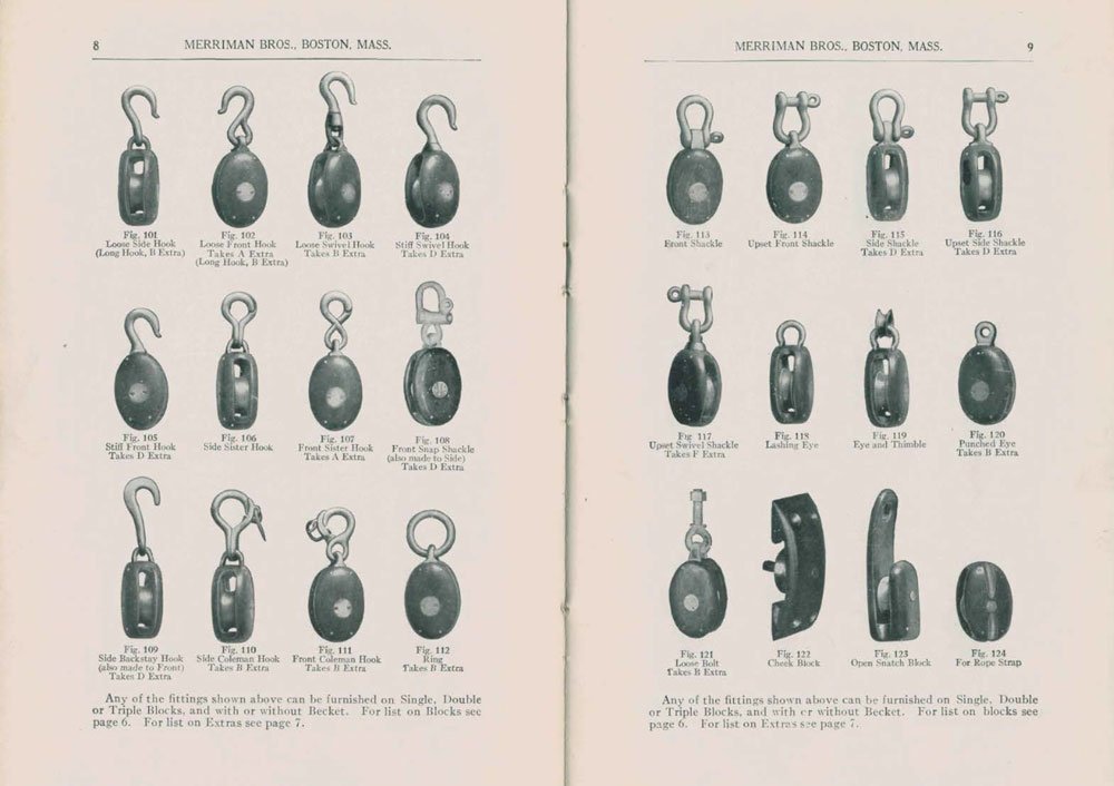
Bridgman, I also read that Merriman were manufacturers of Nat Herreshoff designed blocks.
-
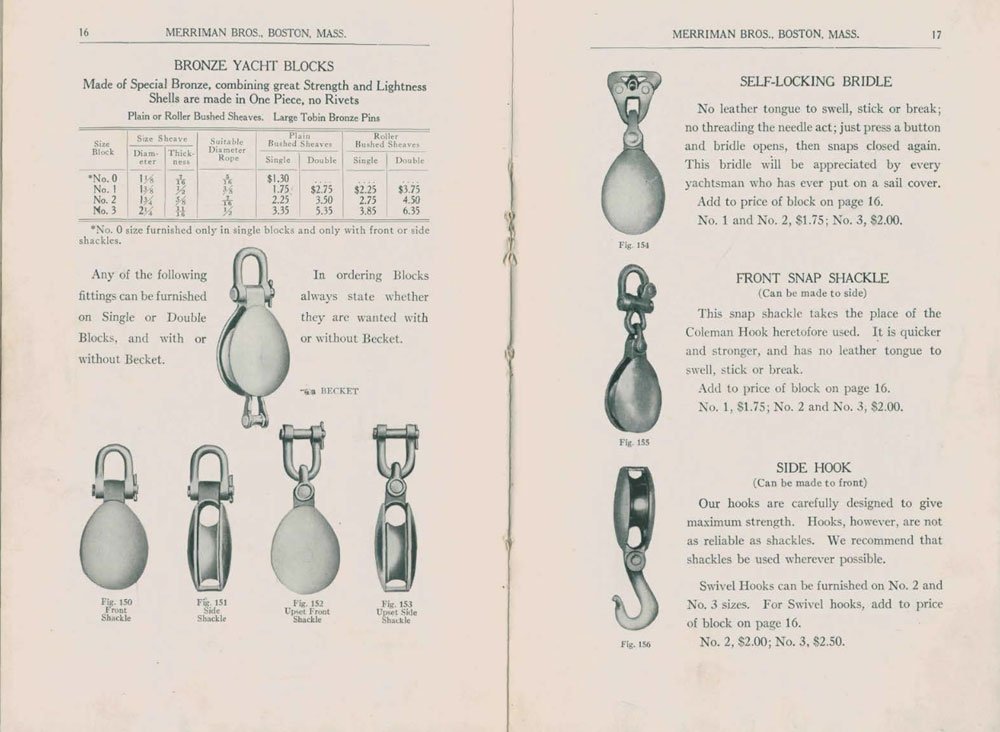
Thanks everyone for your input. Bob, Chapelle's "Boatbuilding" doesn't have an appendix, per se, but he does say that "Blocks having wooden shells are preferable for rope, those having metal shells for wire. Bronze blocks, for rope, are popular, however, because of their small, neat appearance. "American Fishing Schooners" is the one with more extensive rigging sketches and diagrams, but of course, more relevant to schooners. The Merriman suggestion, however, was spot on. I found a pdf of a 1928 Merriman catalog, available from Wooden Boat. https://www.woodenboat.com/sites/default/files/library-content/merriman1928.pdf which I downloaded. There are appropriate wood shell, and bronze shell blocks, along with shackles and turnbuckles, sheet horse fittings, etc. Great resource for my time period. Since my sharpie is not really a working boat, but one that might have built for pleasure or racing, it seems like the small bronze yacht blocks might be appropriate. I'm going to look further to see if I can find a source for galvanised blocks. Those might have been standard hardware store issue. At any rate, I think the Merriman pattern would be suitable for a scale block that could be finished appropriately. Cheers, Cricket
-
Hi Folks, I'm looking for some info on blocks used before the second war. I'm going to be rigging my Chapelle sharpie soon(ish), and thought I might reproduce metal blocks, either bronze or galvanised. But I'm not sure if metal blocks were common. The design from Chapelle is from "Boatbuilding", published in 1941. There is no date on the drawings, but I'm guessing it originates in the 30's some time. the boat is not lines from a hulk or existing boat, but I'm pretty sure new from Chapelle, as he was wont to do at that time. There are many sharpie yacht derivatives penned by Chapelle that were influenced by the work boats of the day. Running rigging is all from 1/4" to 3/8", so a 2" (full scale) block would be about right. I can buy 1/4" iron stropped blocks from Bluejacket, etc. or make my own and paint to resemble metal. Thanks in advance- Cricket
-
Heh heh, I've been known to be "creative" in regards to millwork finish samples in the fussy NYC cabinetry world, too. Sometimes you have to find the spot where the light works to your advantage, before calling the architect and client over.
-
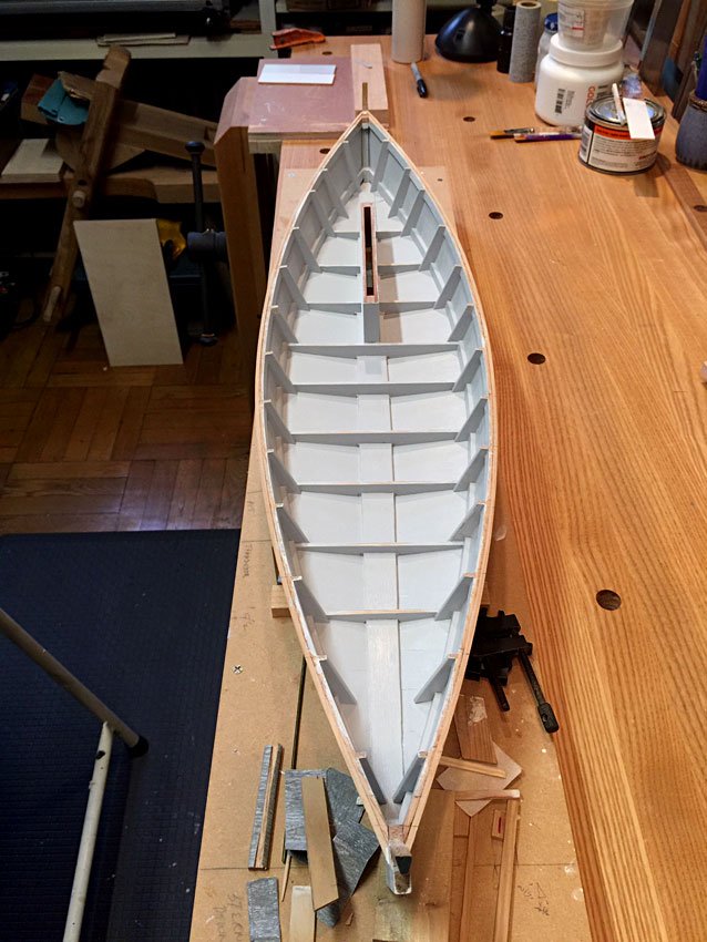
Sand-paint, sand-paint, sand-paint. It’s as time consuming as a big boat. But I got the interior, sans floorboards all done. I have 2 coats of gesso primer inside, leaving or sanding bare the frame heads and tops of floor timbers for glue adhesion later. I pulled our Golden acrylic arsenal out of the closet and mixed a light grey for the interior. I ordered a pint of matte medium, to knock the shine off, but it won’t arrive until next week, but I found a bottle of matte varnish which I’ll use (on a test board first) to knock the slight sheen back. I’m so used to the beautiful soft gloss I get from marine alkyds on the big boats, and I hope I can achieve something similar here, but the acrylics are hard to handle, at least for me. I think I’ll have to move up to airbrushing if I want the perfect finish, though. But not on this model, with no $$ coming in. The first grey I mixed ended up a little too subtle against what will be white decks, so I had to darken it a few steps. I also added some raw sienna for a little warmth. Probably could go further in that direction, but I don’t want to get too tricky with it. Greys and whites are complex, and tough to mix and match. I think I should get the floorboards installed before deck framing, as that will be easier, but to do that I have to shape, paint, and install the centerboard. Another project in and of itself. so that is next. Thanks for looking!
- 44 replies
-
- 10
-
-
You're moving along, and problem solving as you go. That's what boat building is all about. For your next project, you might consider lofting yourself from plans. Besides being worthwhile, in and of itself, it tells you a lot about the boat, and if your lofting is fair, you know your molds and set up will be too. Cheers
-
Brown packing tape is what I've always used for release film. Very thin, and easy to apply.
-
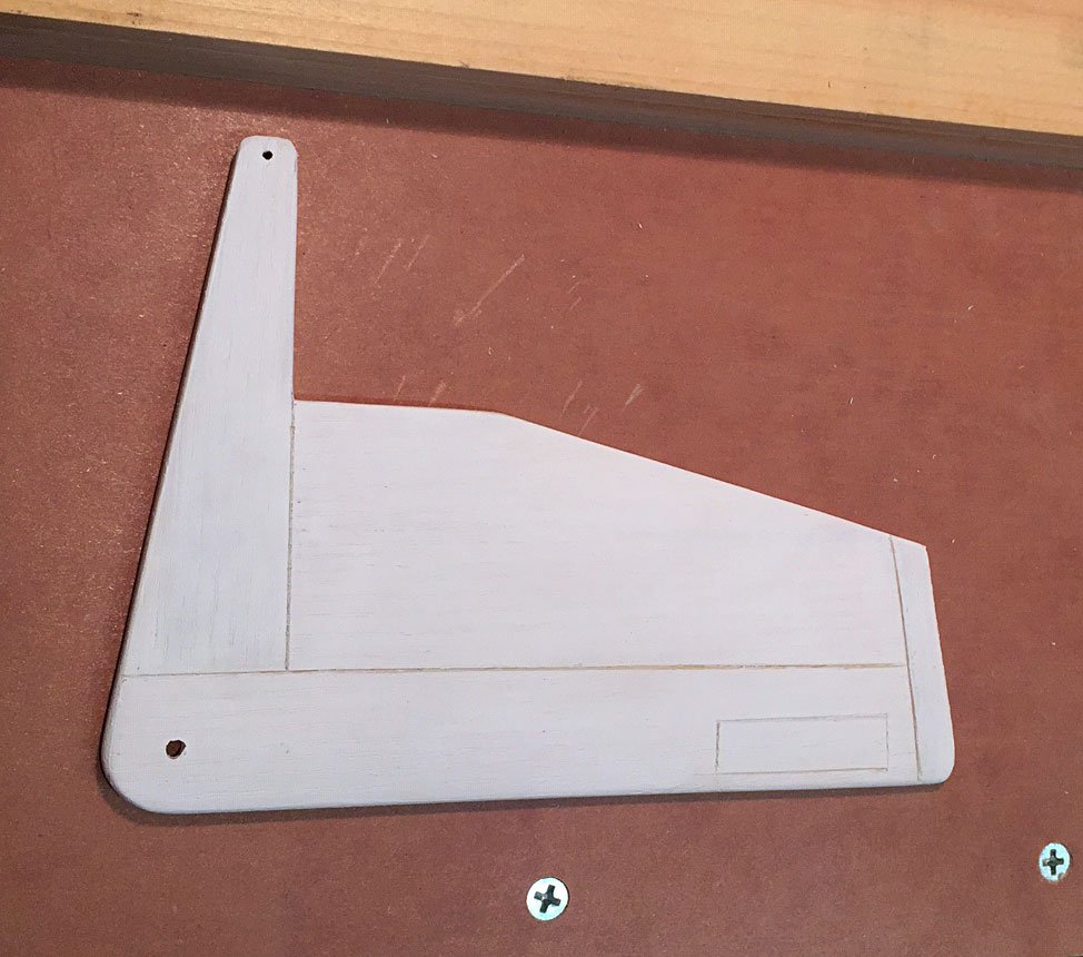
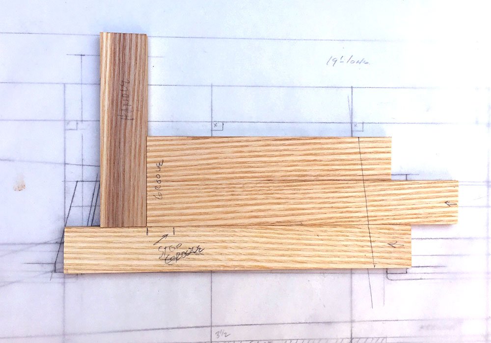
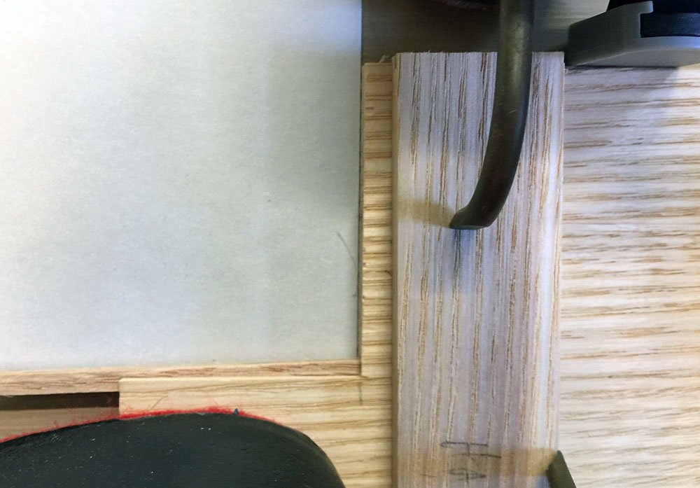
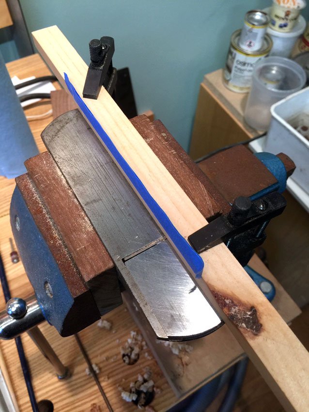
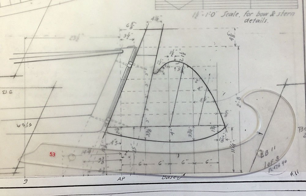
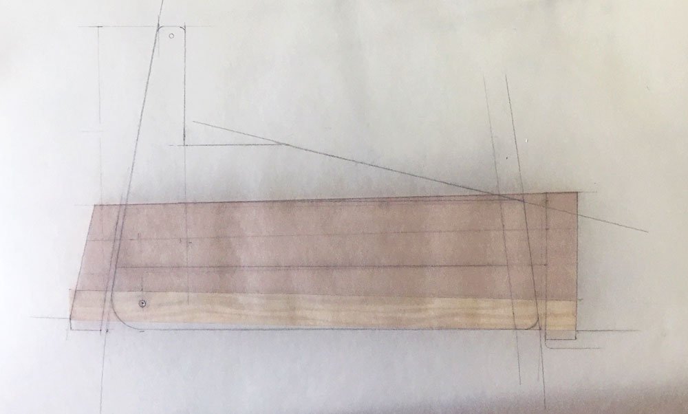
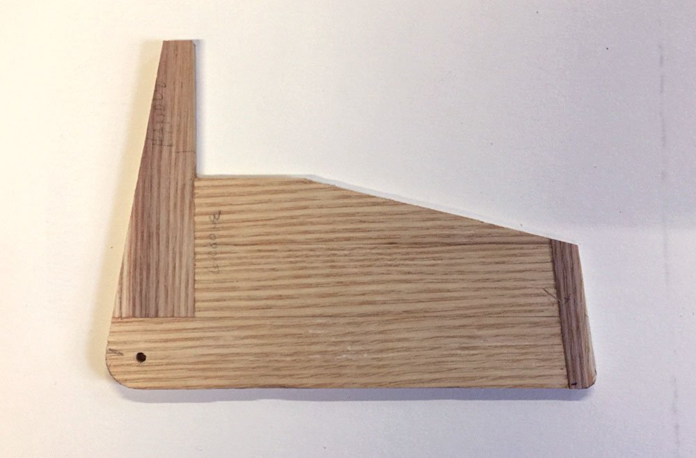
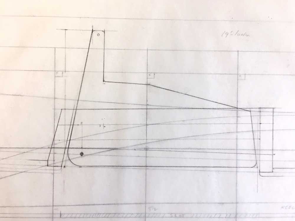
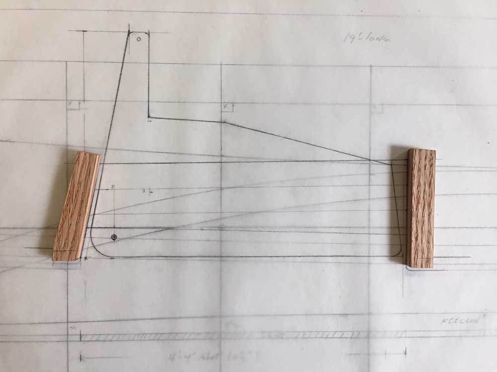
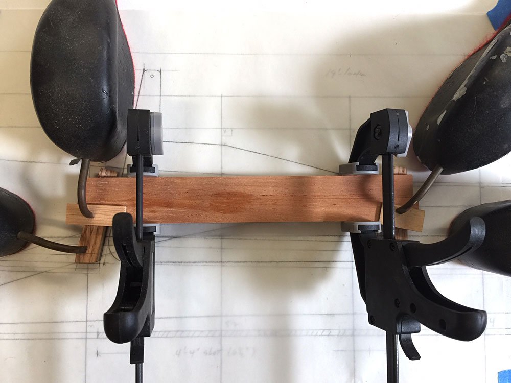
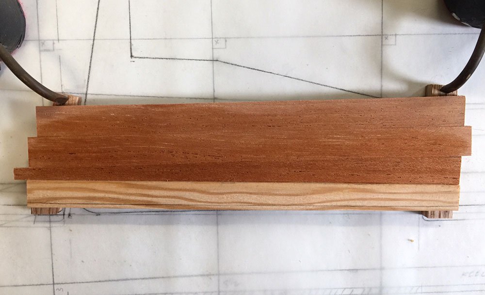
I had to take a couple of days away from the model to work in the garden while we had a weather window, but the roses are all tied up, and the grass is cut. I got the centerboard trunk completed, but I wanted to get the board itself cut out and glued up, so I could drill both it and the trunk for the pivot rod at the same time. Then, while I was at it, I decided to get the rudder made as well, since some of the operations on the table saw were similar. The centerboard handle and lower end both run across the grain of the long planks. In the original construction of these boards, all the pieces were drifted together with steel or bronze rod (steel, more likely). For the model, I decided to spline the assemblies together. I could probably have just glued these end grain to long grain parts, but why not do it right? My thin kerf blade is about 3/32”, and the board about 7/32”, so it would just work, with enough meat outboard of the spline kerf. The spline is evident in the above pic. All of my stock was rough edged, so I made a little jointer again with the block plane in a vise, and a fence clamped to the plane. With tape shims, I can control the angle of the cut pretty well. I got all of the parts for both centerboard and rudder cut, jointed, and splined, then glued them up. The rudder on the Chapelle drawing is shown at 1:8, so all I had to do there was trace it onto vellum. I used only one of my curves for all of the rudder. Trusty old #53 gets used a lot. The centerboard had to be redrawn at the proper scale, however. To locate the pivot point for the trunk and board, I put my vellum layout right on top of them and marked the centers for both with a push pin. My pivot at the moment is a piece of 1/8” bronze rod. I’d like to use a small bolt with nut and washers, but it looks like I have to order 25 of each of them, which will cost a fortune. I may end up just gluing the rod in place after I assemble it all permanently, as it actually looks okay in the boat. Anyway, I checked the pivot geometry with the board in the trunk, then assured myself that I could install the board from the bottom, after the boat is completed. I’ll now go ahead and glue the trunk in permanently. I can cut out the finished rudder, and shape both of the foils later. For now, I want to get back on the interior. Thanks!
-
I don't see any reason why you can't set two or three molds up inside the upright boat, with the bottom, chine, and keelson structure assembled on the upright, curved bottom jig. You'll have to temporarily brace them plumb, and make sure the correct mold is in the right place. Some deadrise builders set the sheer plank, then frame the boat, then fill in the planks between chine and sheer.
-
Hi Dave, are you not planking up around the molds shown in your pic? I have not read the monograph. I'll have a look at in the am. Seems like the keelson and chines can be installed on the molds you have, and the planking wrapped around, but maybe I'm missing something.
-
A quick post this evening. The frames and floors are in, except in way of the centerboard trunk. Those floors will butt the bed logs, so I wanted the trunk in place first. There will be two sets of frames left. I laid the trunk drawing out on a piece of vellum, overlaid on the lofting, and built the trunk right on top of the drawing. The head ledges were cut out and held in place with the trusty old lead ducks. Those things are as handy as a flashlight to have around for things other than drafting. I glued the top two planks of the case sides on first, with the ledges spaced carefully apart, then the thicker bed log (scribed to fit the keelson’s curvature), then last a tapered plank to close the trunk side. The ducks again hold the parts in place while the glue sets. After gluing the first side, I trimmed the ends of the planks flush, and cut the top of the ledges. It slipped into the keelson notches without too much fussing. So I still have to plank the other side, and try hard to not forget about the PIVOT BOLT before I install the trunk! That would be a problem to get right after the fact. I will have to decide how I want to engineer the pivot. I have my own method, which involves plumbing nipples and caps, and works great, but might not be period appropriate. I welcome any comments or criticism. Thanks for looking.
- 44 replies
-
- 11
-
-
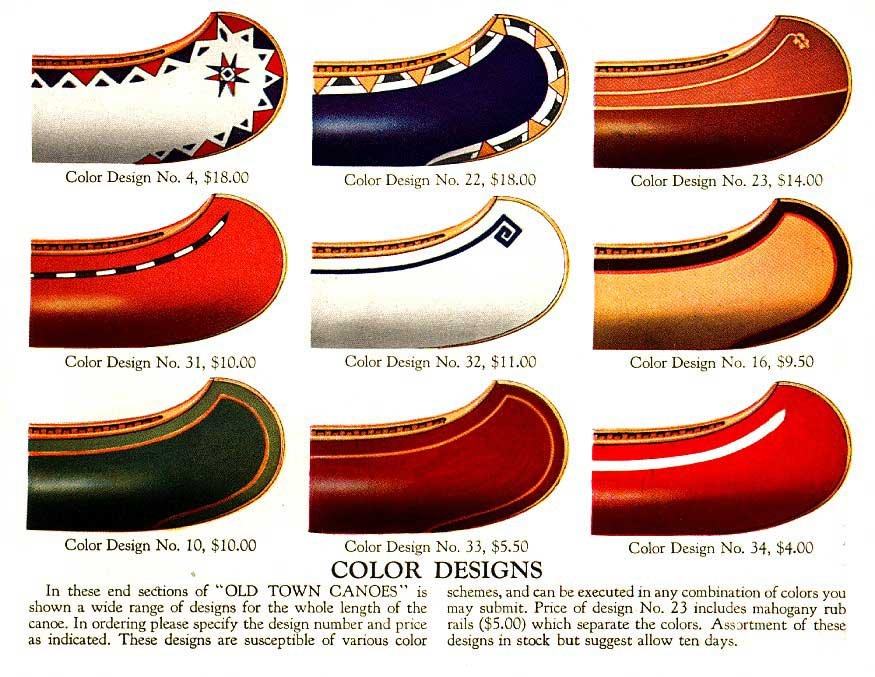
Good move. There are a lot of color scheme references out in web land, if you are interested. A quick search for old town colors brought up this.
- 69 replies
-
- 2
-
-
- restoration
- plank
- (and 3 more)
-
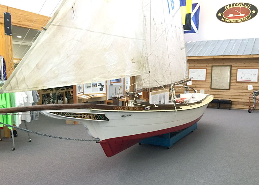
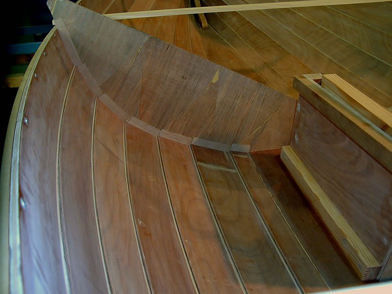
Hi Roger, Yes, Chapelle shows chunks, but my assumption was that most recent boats ( by that I mean mid 20th c.) were staved instead of chunked. The chunks were a holdover from earlier times. Larry Chowning in his book "Deadrise and Cross Planked" states that head blocks or "chunks" were a holdover from log canoe days, and that builders soon went to staves. However, I realized after planking the ends of this model that chunks in this particular case might be preferable, because the staves are so short. The chine in this case does not climb very high on the stem. Also, I couldn't get my mind around the junction of the head block, chine logs, and keelson. Most bateaux, and other deadrise boats after about 1940(?) were staved up, and some like Maryland crab scrapes were even planked fore and aft right up in the bow. This pic below is of a Carl Pedersen built bateau that Joe Gregory drew in the early 70's that is now in the Deltaville museum. So, I think there are examples of both. I'd like to ask John England (Deltaville boat shop manager and board member) his opinion about staving vs. head block construction for some of the lower chined boats like this one. At any rate, I appreciate the discussion about this or anything else that comes to mind. I think that if I build a model from the Chapelle bateau drawings that I have in my flat files, I'll try the chunks. Thanks!
-
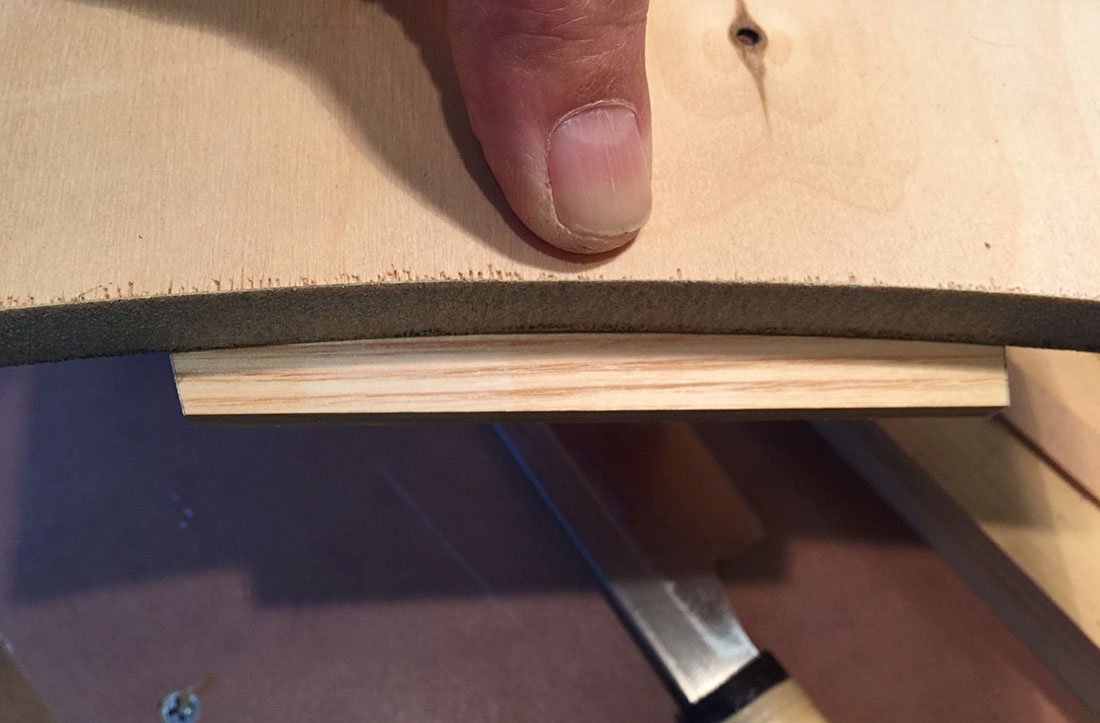
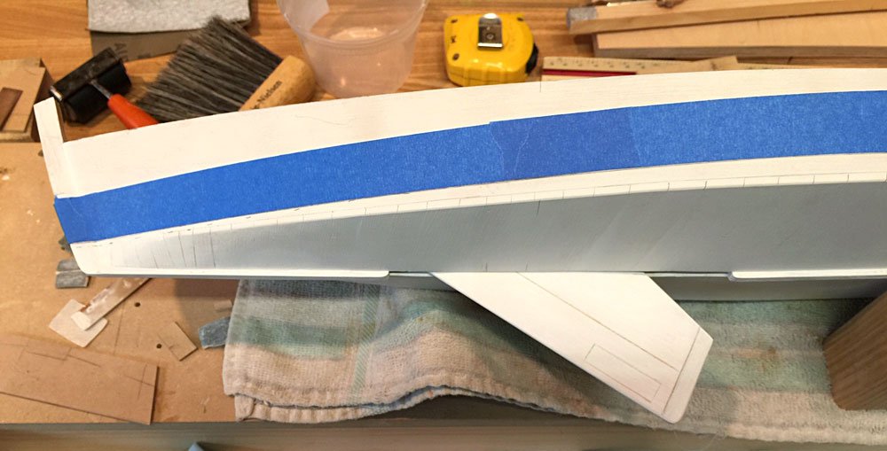
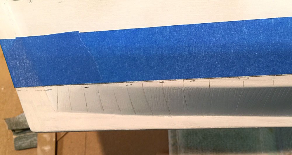
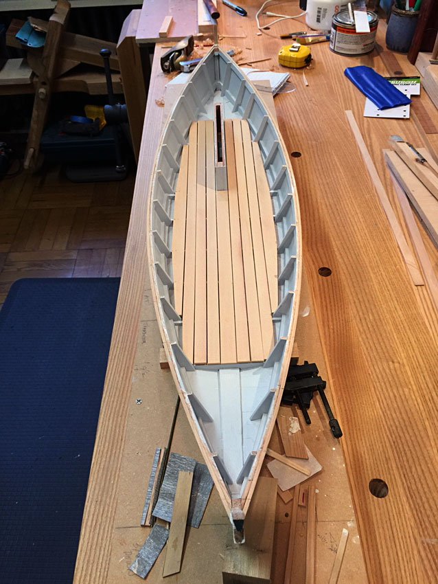
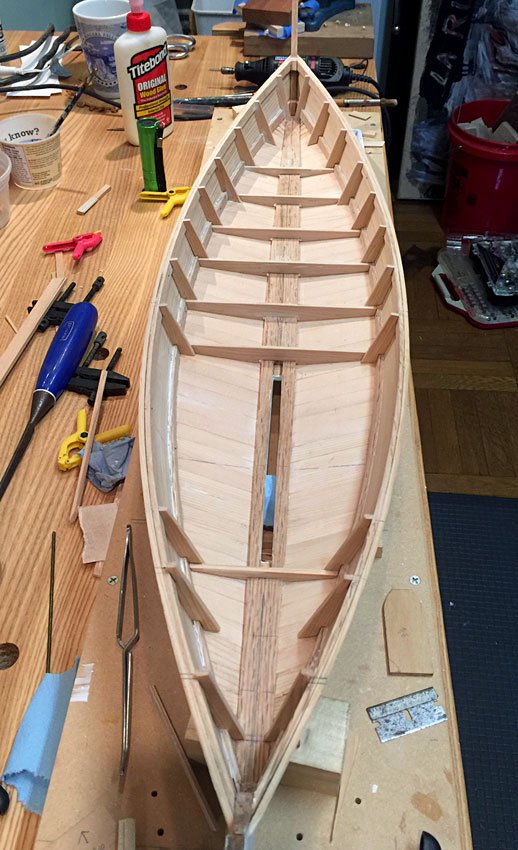
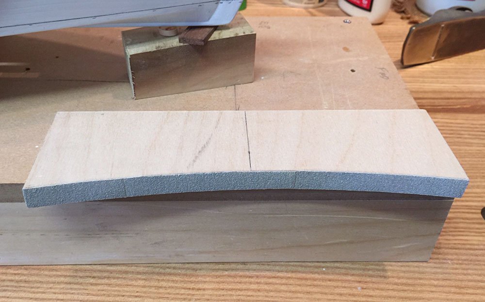
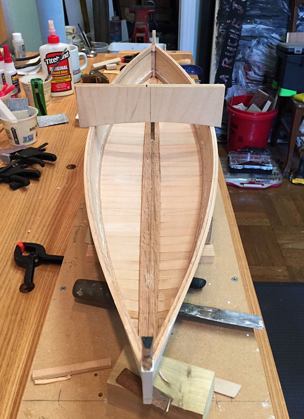
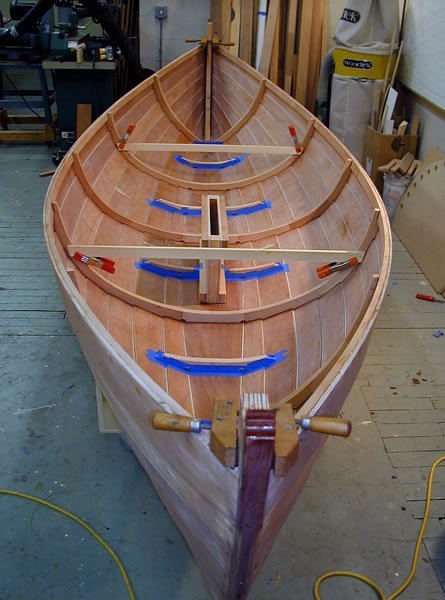
Thanks for the comment, John. And thanks to those looking in and hitting the like button! I had a bit of work to get the planking at the sheer cut down and fair with the sheer clamp, and with the correct bevel. My usual procedure is to make a master deck crown template, and use that everywhere to set the sheer bevel. That doesn’t work on all decks, like turtle backs, or decks with a variable crown, but for many traditional, half decked boats, it works fine. For the model, I went a step further and lined the radius edge with 120 grit sandpaper, so that once the sheer is close I can use the radius block like an automatic fairing tool. It can be used side to side, and fore and aft. As long as the plane doesn’t over cut the bevel, the sanding tool does a great job of hitting the bevels exactly. With that done, I turned to the framing layout. After thinking about this design for a while, I decided to make some small changes in the layout, to suit myself, as if I were building this full size skiff for my own use. This is not a set of lines taken from an existing hull as Chapelle often did, but a new design of his based on the double ended crab skiffs of the day. Also, this is clearly a yacht, rather than a working boat, so I wanted to make it comfortable. I am eliminating the bridge deck, and fitting in it’s place a thwart, set a little lower down. This makes possible a set of rowlocks, and opens up the forward area somewhat. Also, I’m coupling the floor framing with the side frames, rather than space them as shown in Chapelle’s drawings. The interval is still very close to that detailed, and the structure is stronger. It makes sense to locate a floor and frame at each end of the centerboard trunk, tying those structures together. The frames at the forward end of the trunk will also be tied to the deck beam that defines the aft end of the forward deck. Likewise, I put a set of frames at the aft deck opening. Without the bridge deck, the floorboards can be continuous, and I set them up so that the tops of all the floor framing is coplanar. So there is now a 12’ stretch of flat, unbroken sole for the entire length of the cockpit. To do that, I took the midship floor height off of the drawings, then used a straight edge to locate the tops of the foremost and aftermost floors at equal heights, and in line with the midship floor. My crab skiff Cricket has a sole like this, and I loved it. So I’ve got the layout figured, and I’m busy with the fiddly job of fitting all the framing. This vee bottom is pretty simple, and I use a temporary pattern “bulkhead” clamped to a little block that is held to the keelson with a drop of glue. I use a little gauge of consistent width to create offset lines which I then transfer to my framing stock. On a full size boat, I use little tabs and hot glue, but that is not practical here. I think my method is apparent from the pics. Fitting frames and bulkheads to a round bilged, lapstrake hull is another matter entirely. This one is comparatively easy. Note the pics of frame templates, and finished frames in my Matinicus Double Ender, below. So I’ve got a bit of work ahead of me, before I can begin the deck framing. I realized that in my haste, I had forgotten to cut limbers in the floors at the keelson, so I’ll have to go back and put them in where I’ve forgotten them. They are curiously absent from the otherwise well detailed Chapelle drawings. Stay tuned…. Cricket
- 44 replies
-
- 10
-