HOLIDAY DONATION DRIVE - SUPPORT MSW - DO YOUR PART TO KEEP THIS GREAT FORUM GOING! (Only 24 donations so far out of 49,000 members - C'mon guys!)
×


SkiBee
-
Posts
249 -
Joined
-
Last visited
Content Type
Profiles
Forums
Gallery
Events
Everything posted by SkiBee
-
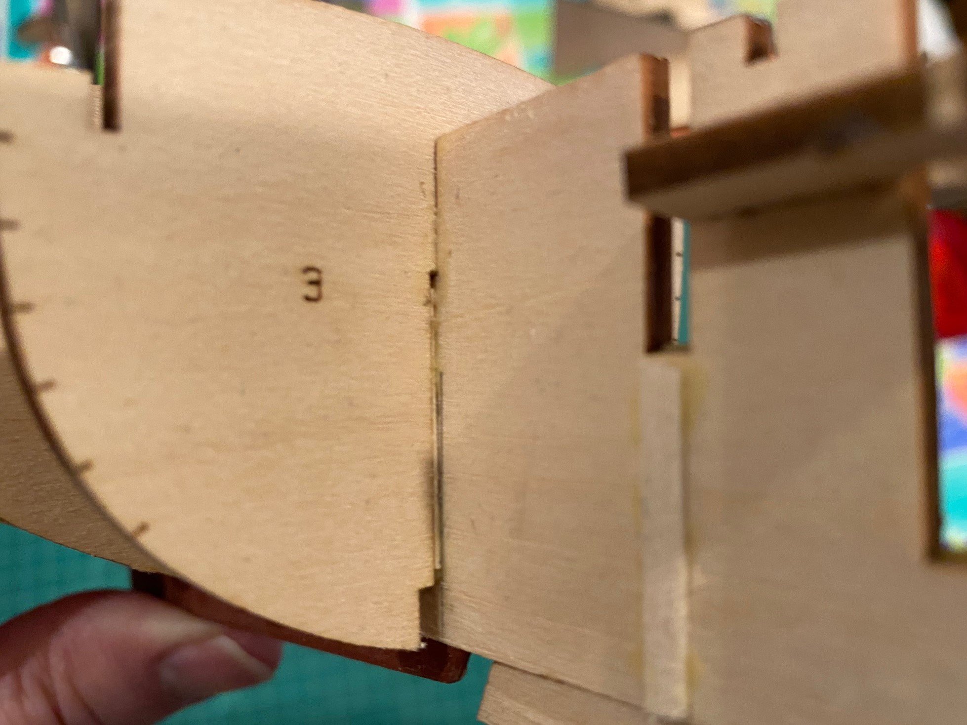
 @druxey I agree, the planks between the bow stem and frame 3 do have some strange curves. I'm not sure if frame 3 is too high or frame 2 is too low, I think it is a combination of the two. The strange curve continues in the 2nd & 3rd plank, by the 4th it starts to lessen. I do use flexible sanding sticks, but this time I used non-flexible sticks and blocks. I think you might have hit on the cause, so next time I’ll use flexible sanding sticks more.
- 62 replies
-
- 1
-

-
- muscongus bay lobster smack
- Finished
- (and 1 more)
-
Received the new hull blank today, I'll restart this boat once I'm done with the Lobster Smack which has been a challenge in many ways but appears to be a good learning experience.
-
GGibson, you have done an excellent job on this model. I built it a few months ago and had a number of problems that you have seem to overcome with ease. Keep up the great work. By the way, I kept a log on this model. Norwegian Sailing Pram by SkiBee - Model Shipways - Scale 1:12
- 26 replies
-
- 2
-
-
- Model Shipways
- Norwegian sailing pram
- (and 2 more)
-
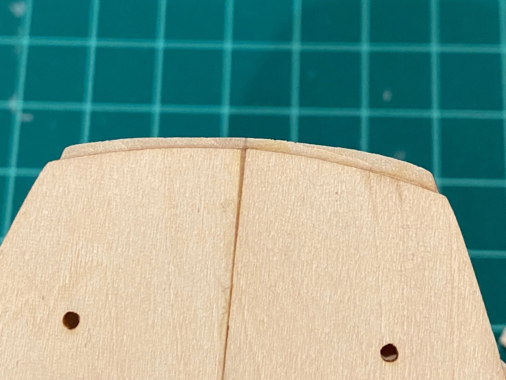
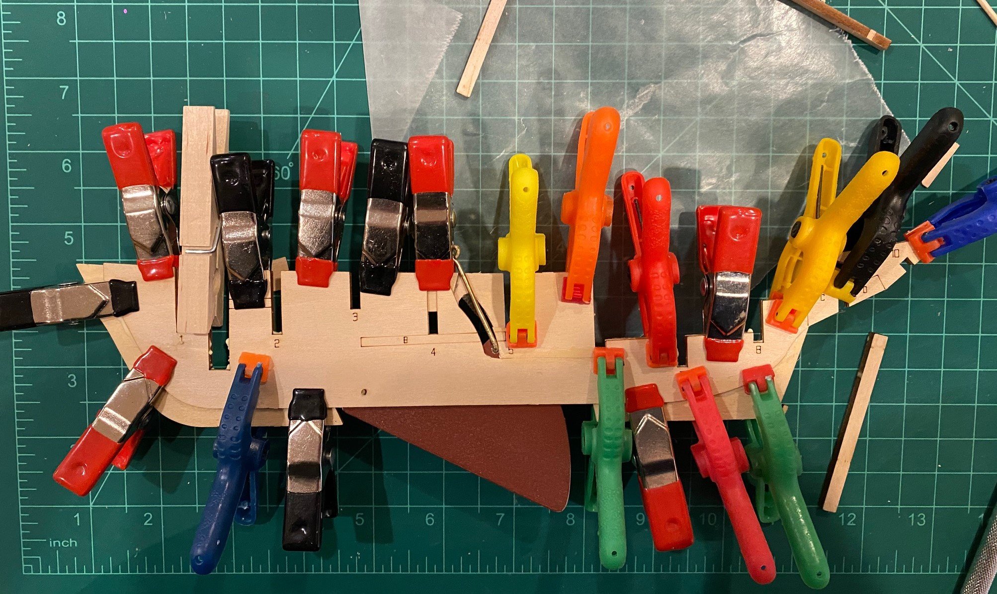
Fairing the hull: As you can see in the pictures above, I had a number of frames that stuck out past the deck. Since the top plank appears to abut the top of the deck on the outside, I had to reduce the frames. For the frames that stuck out, I first used a knife and chisel blade to cut some of the frame down to the deck. I started the cut just down the frame enough so at the end the frame was vertical, no curve to the frame. This was a little tricky since I did not want to cut the deck. I then started to fair the frames, I ended up using an 80-grit sanding block. Fairing Frame 1 and the spine was difficult, trying to get a smooth transition from the spine to frame 2. I used a combination of the 80-grit sanding block, a course sanding stick and some 80 & 150-grit sandpaper wrapped around a ¼ inch dowel. Getting the outside parts of the spine faired like the instructions say was very difficult. I kept sanding groves in the spine. I did end up with a small step between the outside spines and the center piece of the spine. Fairing the aft frames was just as hard, especially the outside spines. I wonder if it would not have been easier to fair the port and starboard spine pieces before gluing to the center spine piece. I cannot see why it would not work and I think I would have ended up with a smoother transition to glue the planks to. I used the ¼ inch dowel on the curve parts of the aft frames, next time I would have a couple of larger dowels to. Since there is no scale schematic of the model to determine the relation of the fwd and aft spine fairing; to the stem, keel and sternpost; to the planks – I would recommend dry fitting the stem, keel and sternpost with some of the planks to see how the fwd and aft end of the planks fit in the rabbet formed between the faired spine and the stem, keel and sternpost.


- 62 replies
-
- 2
-
-
- muscongus bay lobster smack
- Finished
- (and 1 more)
-
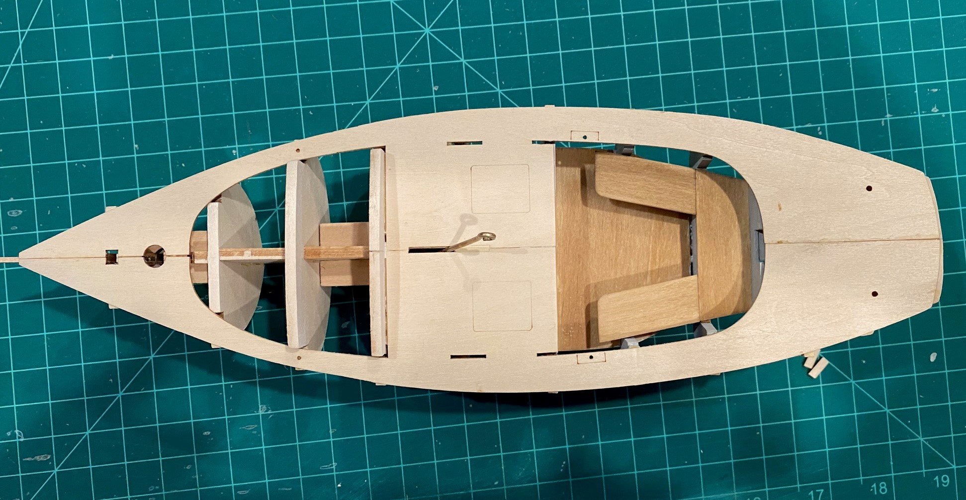
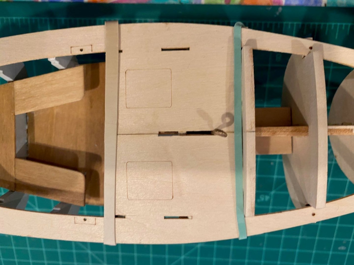
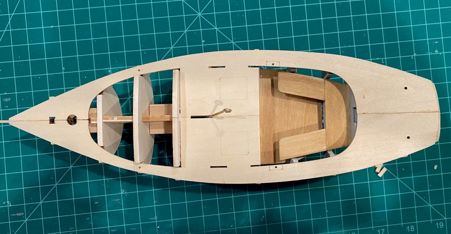
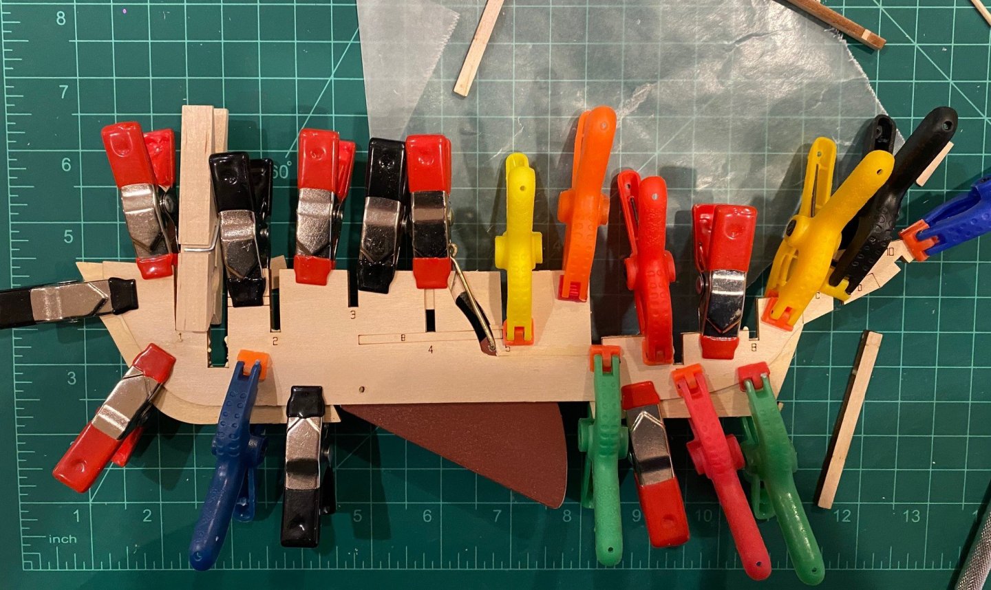
Gluing the deck halves was a real challenge trying not to have a big gap between halves but still have the outside deck edge out to the edge of the frames. I decided to glue the middle area first then work to the bow and stern, this way I could try and get some bend in the deck halves where it was a little narrower. I did have to wet the deck to glue the middle section, but did when I moved to the bow and stern. The deck did not overlap the transom as much as the instruction’s pictures indicate, so I think I’m going to sand the transom vertically to the deck. I did think about filling the edge with wood putty but I think sanding vertically will work and look better. Lessons Learned; I thought I had glued the frames perpendicular to the spine and without tilt, port and starboard, but I would even take more time in the future. Also, take a little more time to fair the top of the frames. I think both of these would have helped reduce the amount of the frames I’m now having to sand/cut down.


- 62 replies
-
- 6
-
-
- muscongus bay lobster smack
- Finished
- (and 1 more)
-
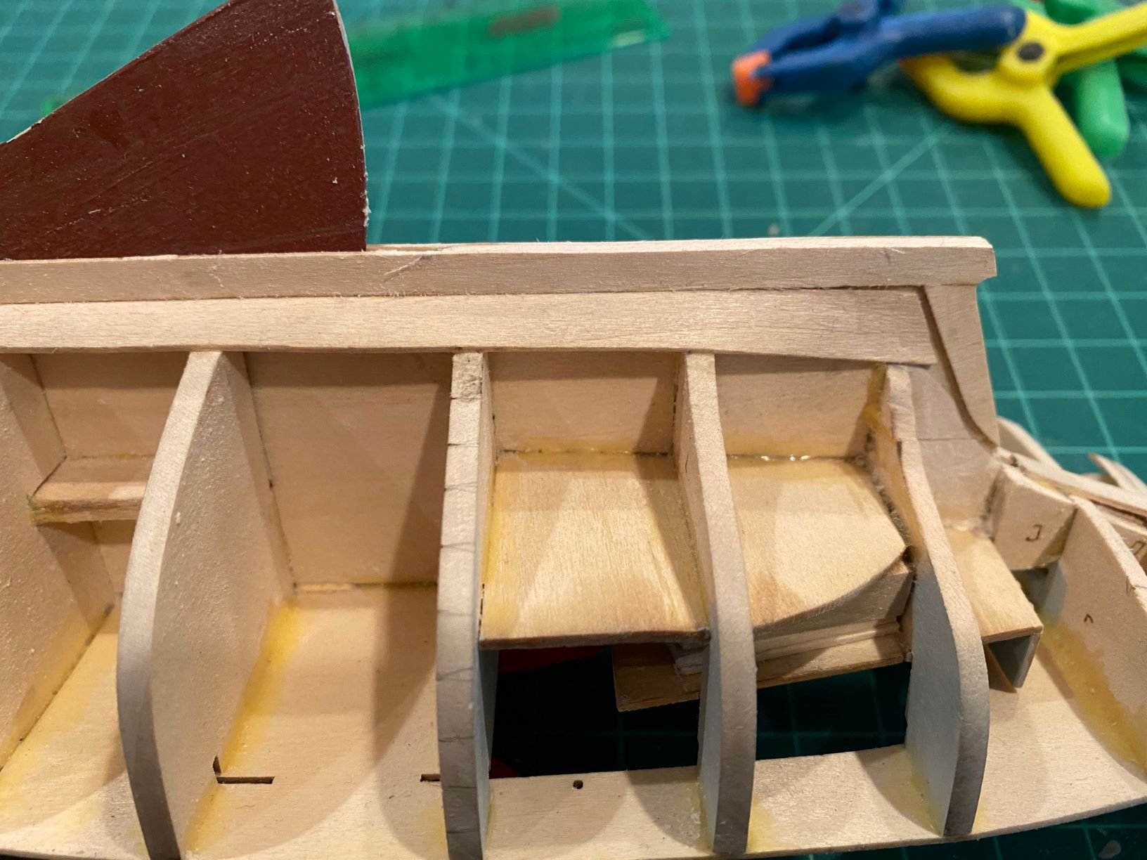
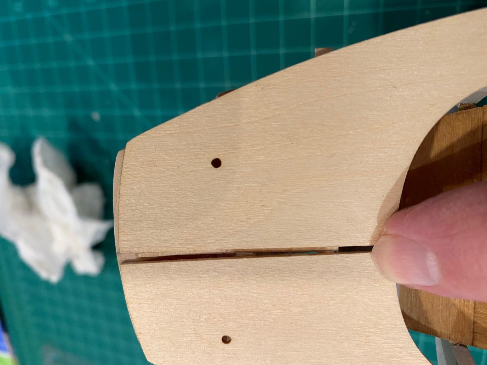
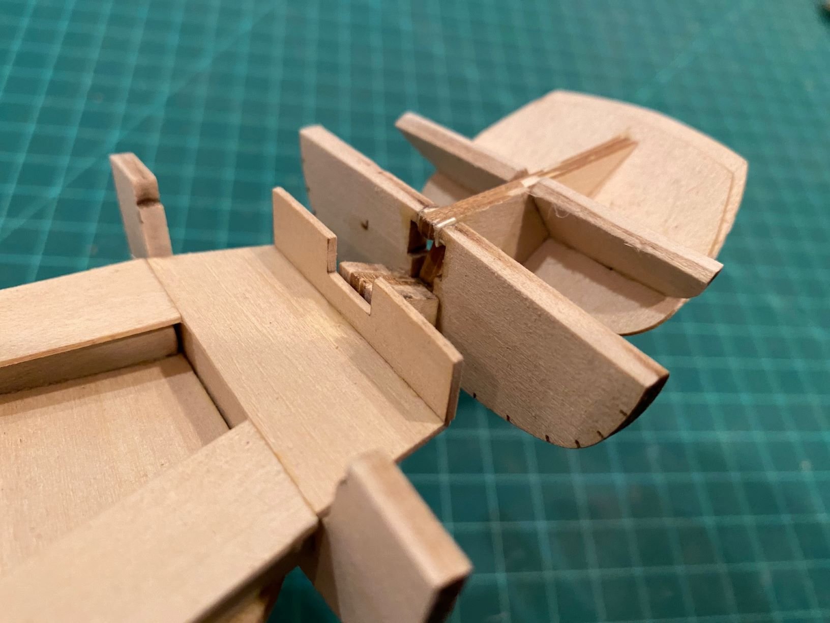
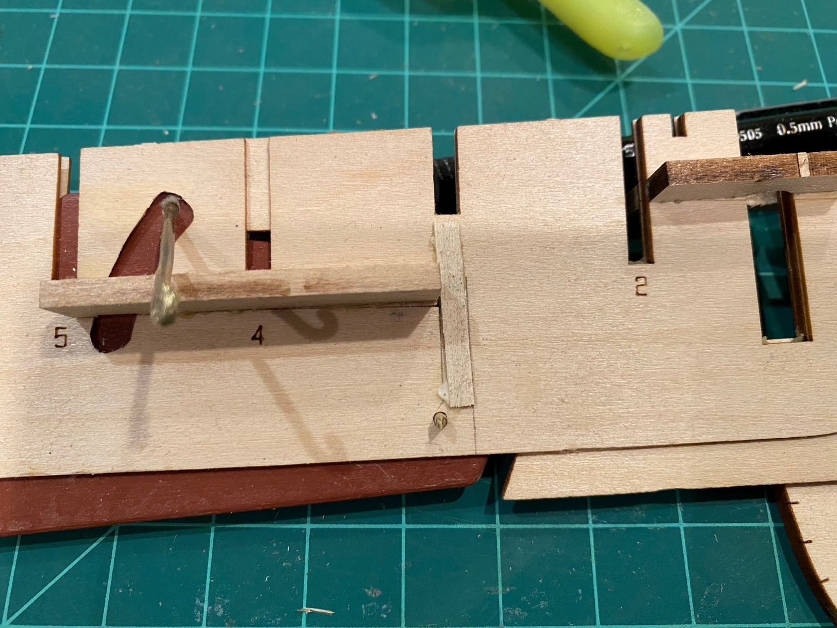
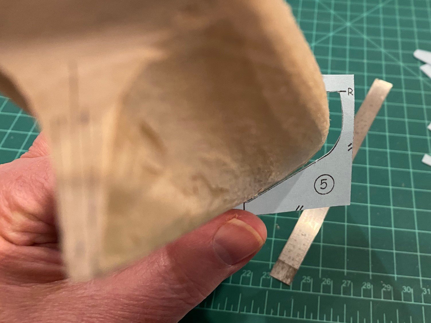
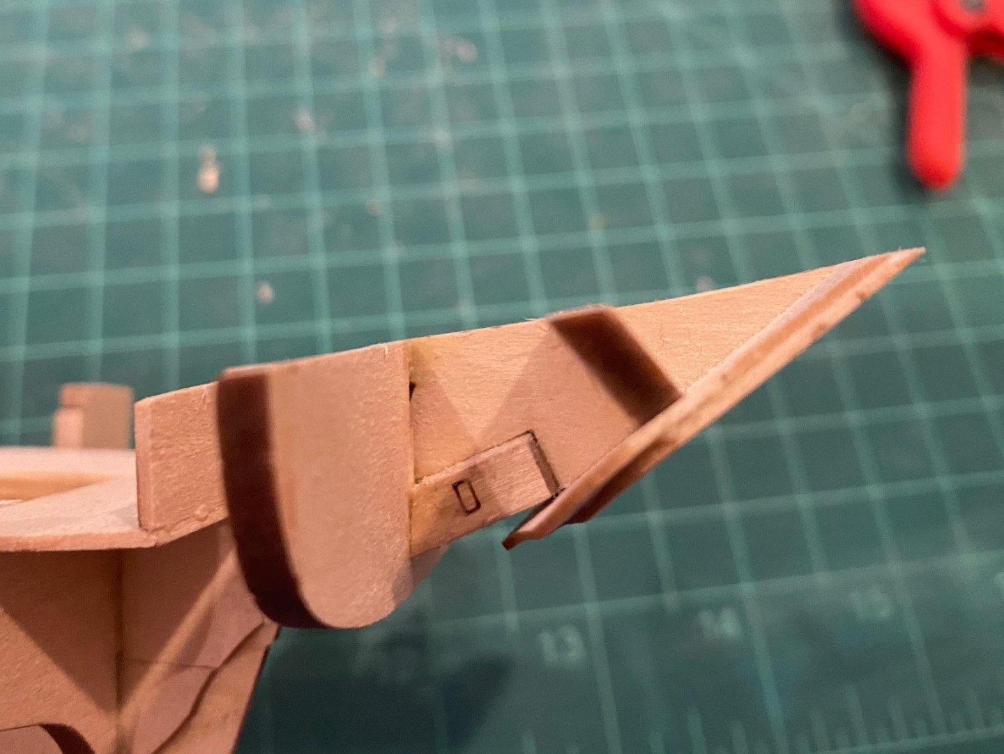
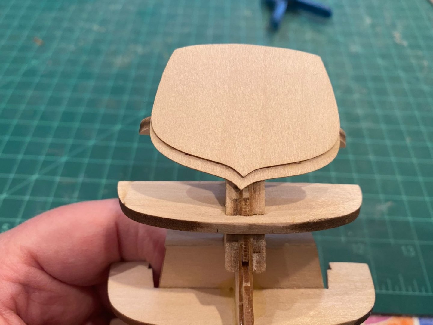
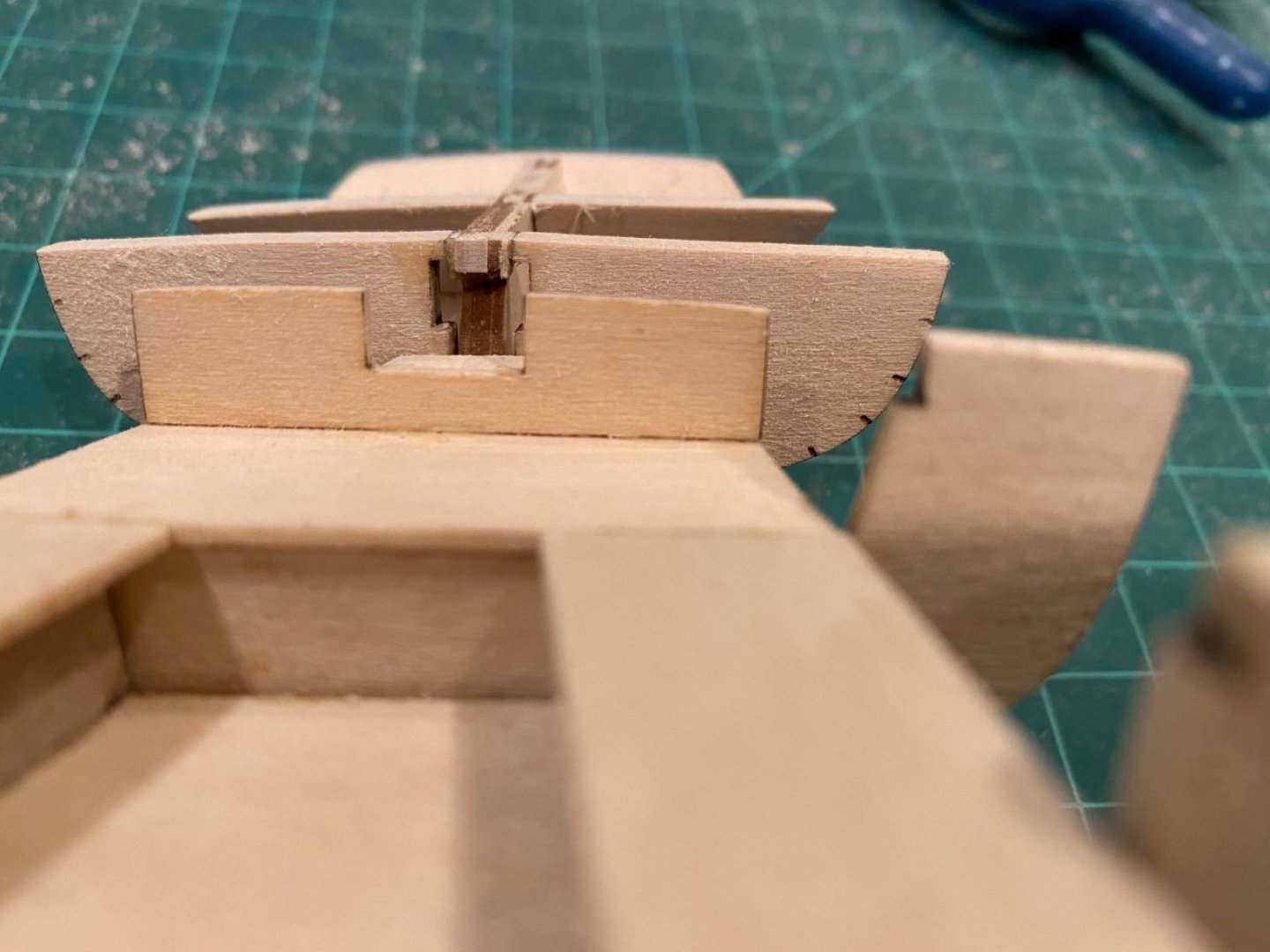
Ed at Model Expo wrote back, “The transom pieces were changed a bit after I built my model because the tabs weren't right, but the sizes weren't changed. You have to make them flush on top.” I did clarify he meant the transom should be flush with the spine. I needed to remove almost 1/4 inch from the top of the transom to be flush with the spine. I used a sanding stick since I was concerned about breaking the top of the transom using anything else. It took quite a long time but I got it down, see below pictures. I would recommend cutting the top of the outside part of the transom down prior to gluing it to the other side of the transom. I would try and dry fit the frame 10 and two transom pieces to the boat to determine how much to cut it down. @JohnN mentioned, looking at the bottom of the transom in relation to the other frames and spine. You can see mine is skewed to the port, I needed to check it better before the glue set. Then I faired the rest of the frame tops to get an even surface over a few frames at a time to ensure a smooth deck. My frame 6 was noticeably higher than the frames around it so it took some effort and time to get frame tops to have a smooth transition across the top.
- 62 replies
-
- 2
-
-
- muscongus bay lobster smack
- Finished
- (and 1 more)
-
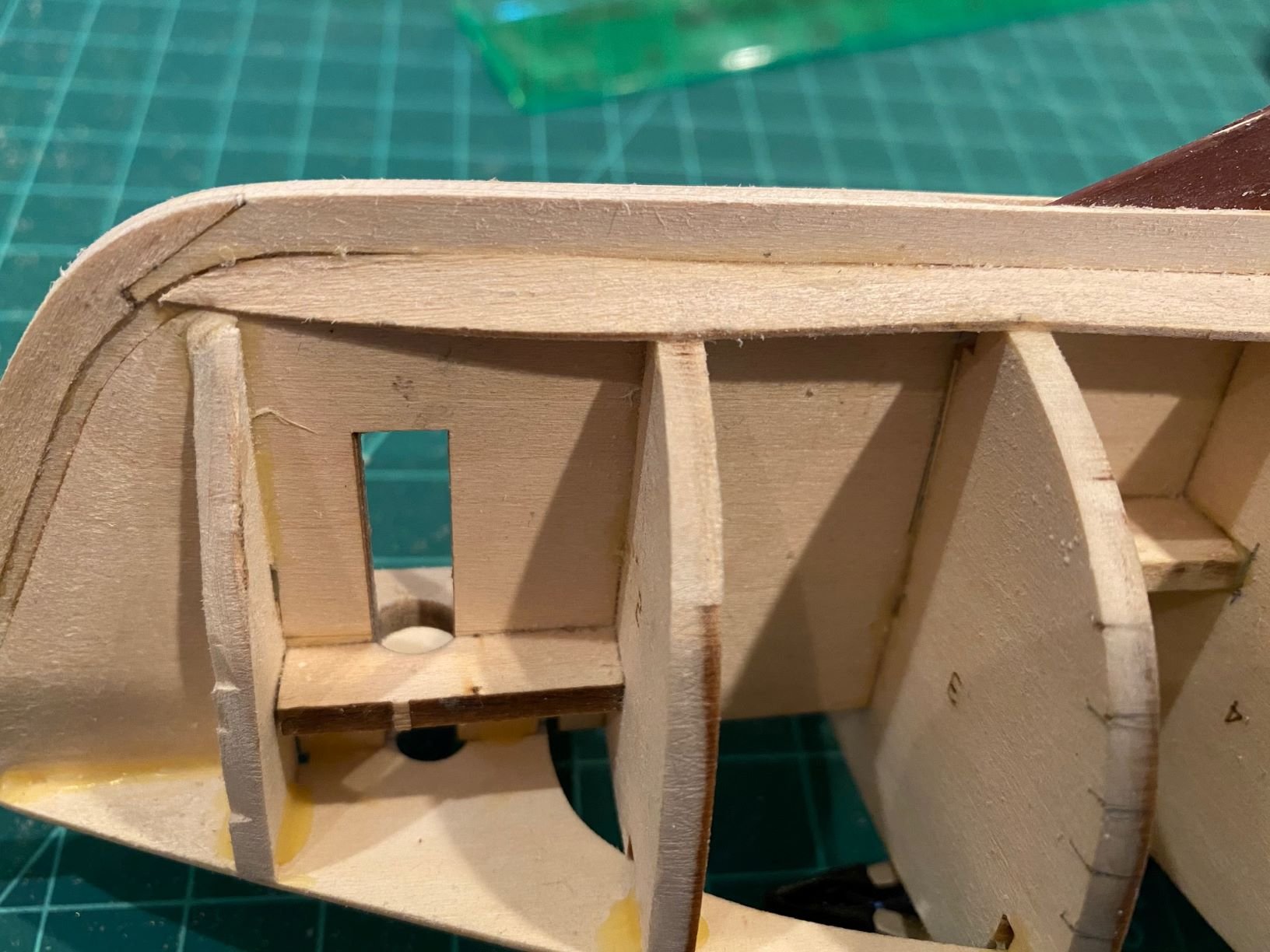
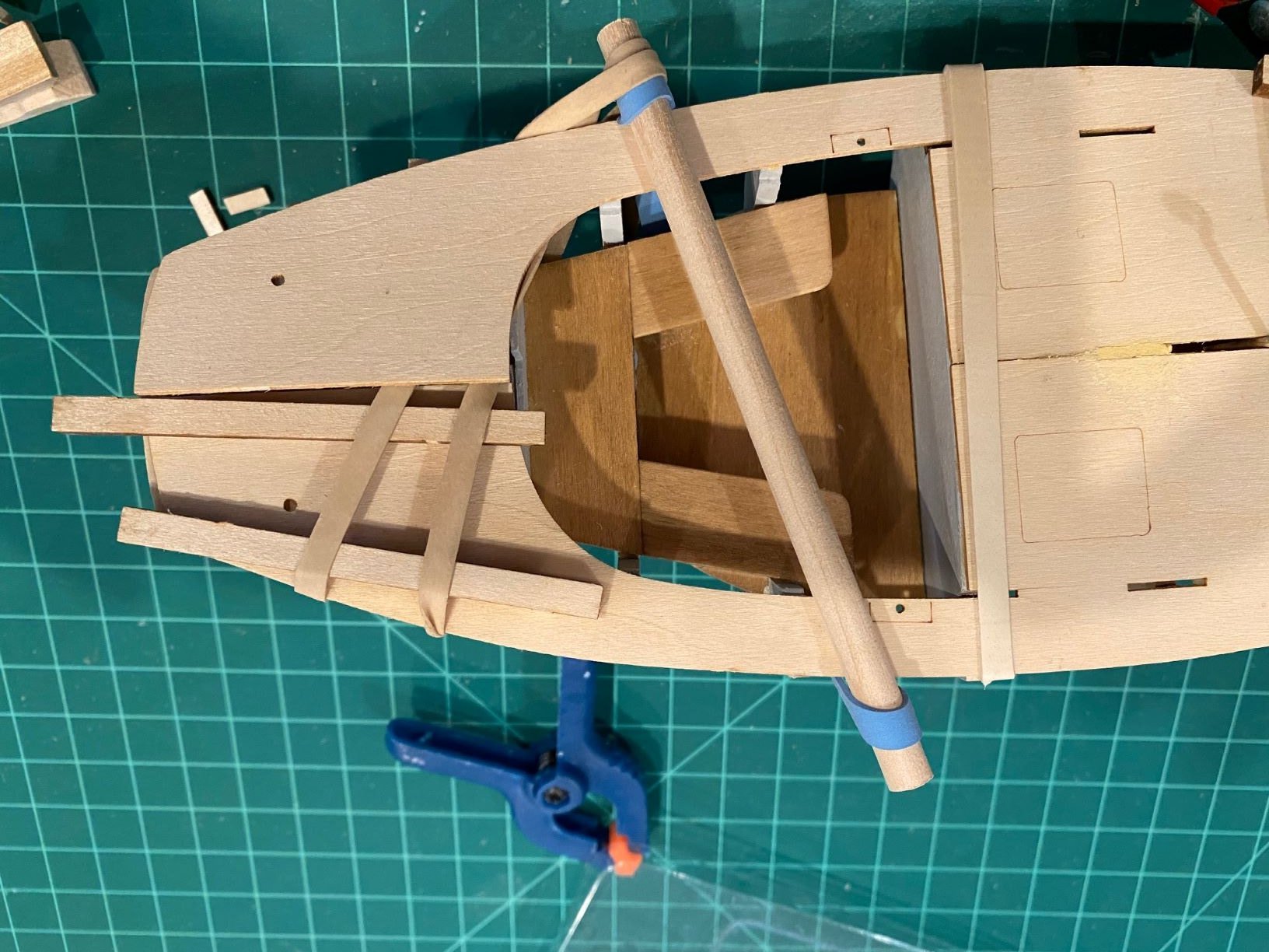
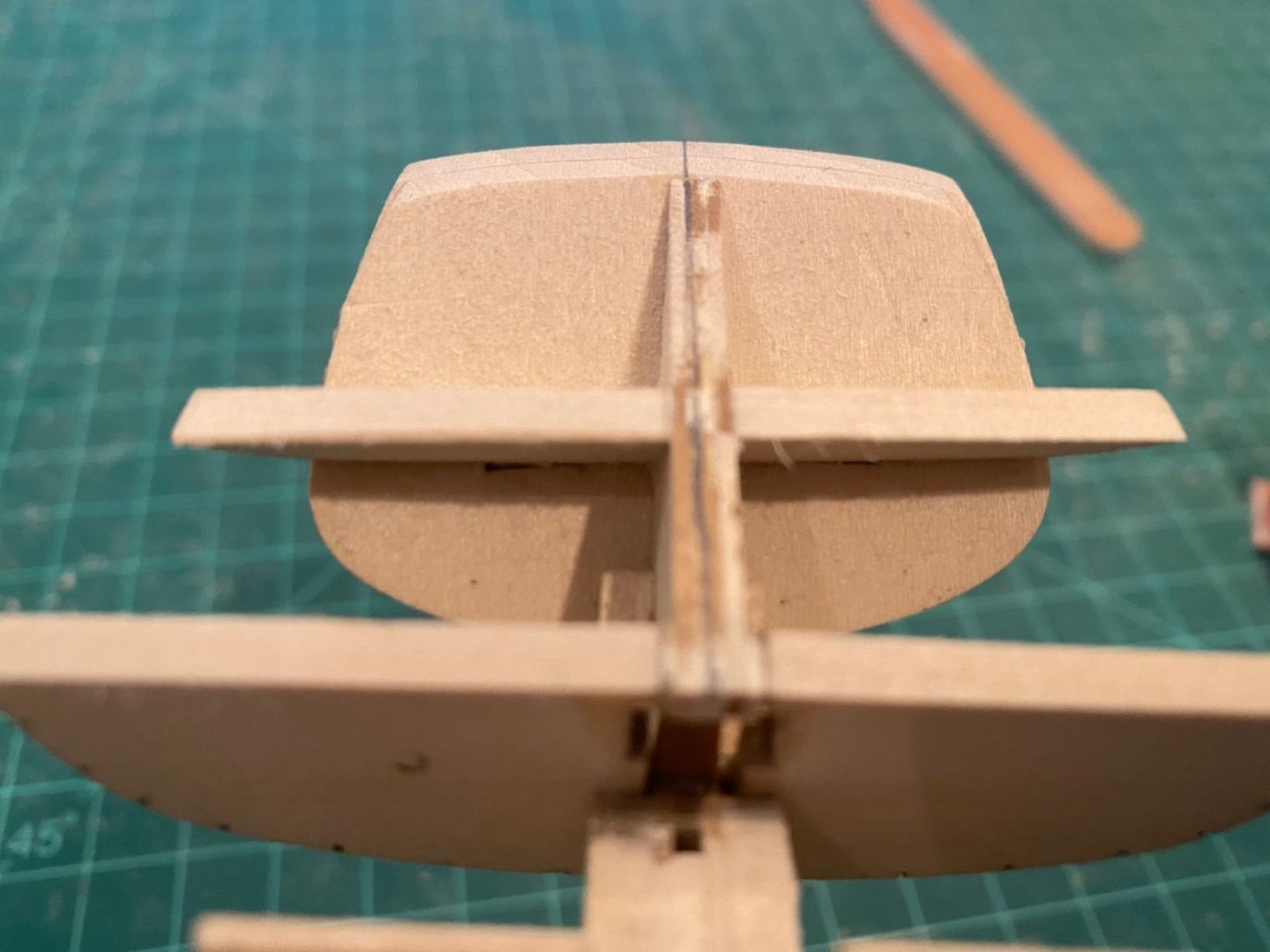
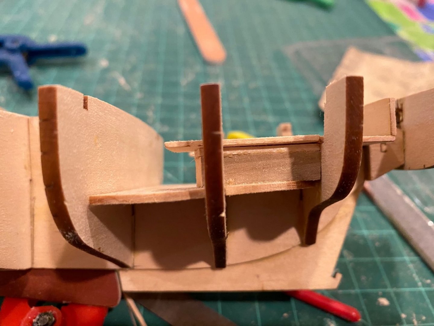
I installed the cockpit floor and seats, but I made a mistake in not catching that I did not install the floor flat, mine curved up as it went aft. This led me to install the side seat risers flat (low) instead of wider side vertical. The below picture shows the results, at first, I was going to leave as is but as I looked at it more it did not look right to have the side seats slope fwd. I used some alcohol to loosen the glue on the floor, seats and risers. I could not get the risers loose so I decided to shim the seats once I re-glued the floor. As I was trying to loosen the risers, I broke the model in half at frame 8. Glued the model back together and reinstalled the floor and side seats with shimming. Looks better. In picture below, you can see that the spine and stiffener C stick out above the center cutout of the rear seat back where the tiller goes. The instruction picture on page 7, shows this flat. I’m concerned that this issue will interfere with the tiller/rudder assembly. So I used a knife and trimed the stiffener/spine level with the cutout. I then started to fair the top of the frames/spine so I could install the deck. First, the instructions on page 7 say, “… sand the top of the transom until it is flush to the top of the spine at the center …”, also see the pictures on page 7, it shows that the spine is much higher on the transom than mine. But when I installed frame 10/transom it is significantly above the aft spine compared to the instructions. I would have to take off a significant amount of transom to make it level, see the above picture on the left. I believe I installed everything correctly, is this an issue due to change in prototype vs production kit. I wrote back to Model Shipways/Expo to see what there take was. I don’t mean to be a broken record but if there was a to scale schematic of the model included in the instructions like it is for the Grand Banks Dory, it probably would answer my questions.


- 62 replies
-
- 3
-
-
- muscongus bay lobster smack
- Finished
- (and 1 more)
-
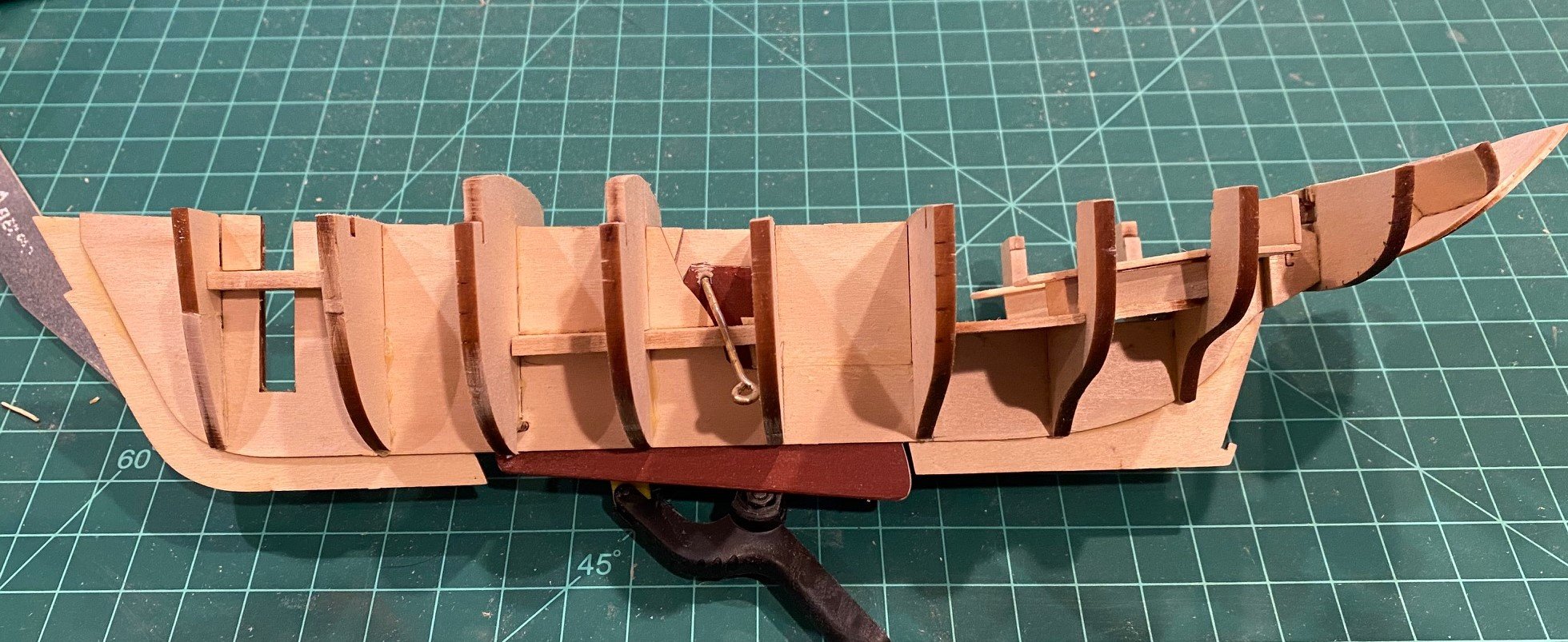
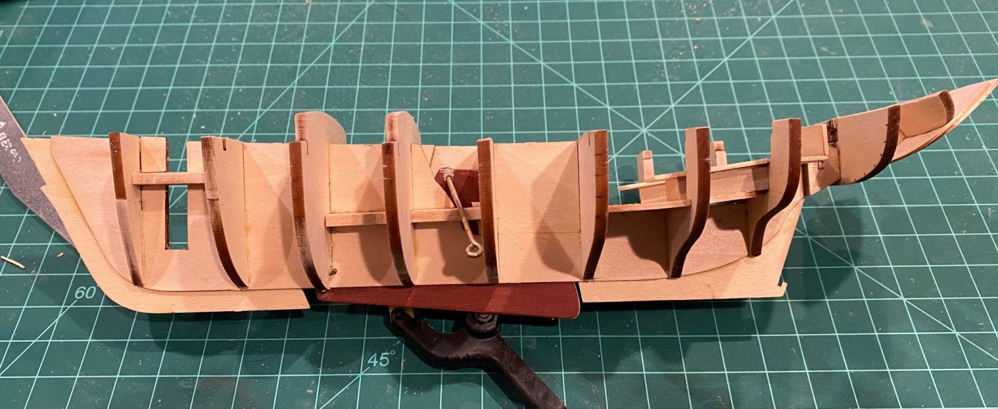
I’ve installed all the bulkhead frames, a couple of points on my approach. The shims worked well on all the frames except 1, 9 and 10. On Frame 1, I should have fit checked it prior to gluing, the shimming was a little to thick for the frame and I broke off one side of the frame. I still think you should shim the frame if you had the same problem that I did but fit check more as you go in case you have to thin the shims. Frame 9, the frame only comes into contact with a small space at the top and bottom of the spine. I only shimmed the top, but when I glued it in, I did not align the bottom correctly so the frame was off line from port to starboard. So, either shim both top and bottom or be careful to make sure that the frames is level. (I should have taken a picture prior to installing frame 10. Frame 10 did not need any shimming, it fit as supplied on the spine.

- 62 replies
-
- 4
-
-
- muscongus bay lobster smack
- Finished
- (and 1 more)
-
JohnN, Yes I had to shim all of them except frame #4. Edit: I did not have to shim Frame 10 and I shimmed Frame 1 a little to much, see below.
- 62 replies
-
- 1
-
-
- muscongus bay lobster smack
- Finished
- (and 1 more)
-
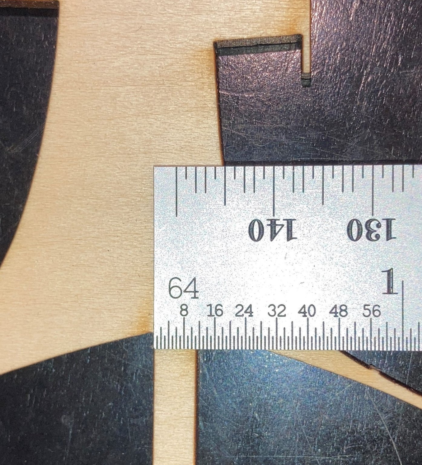
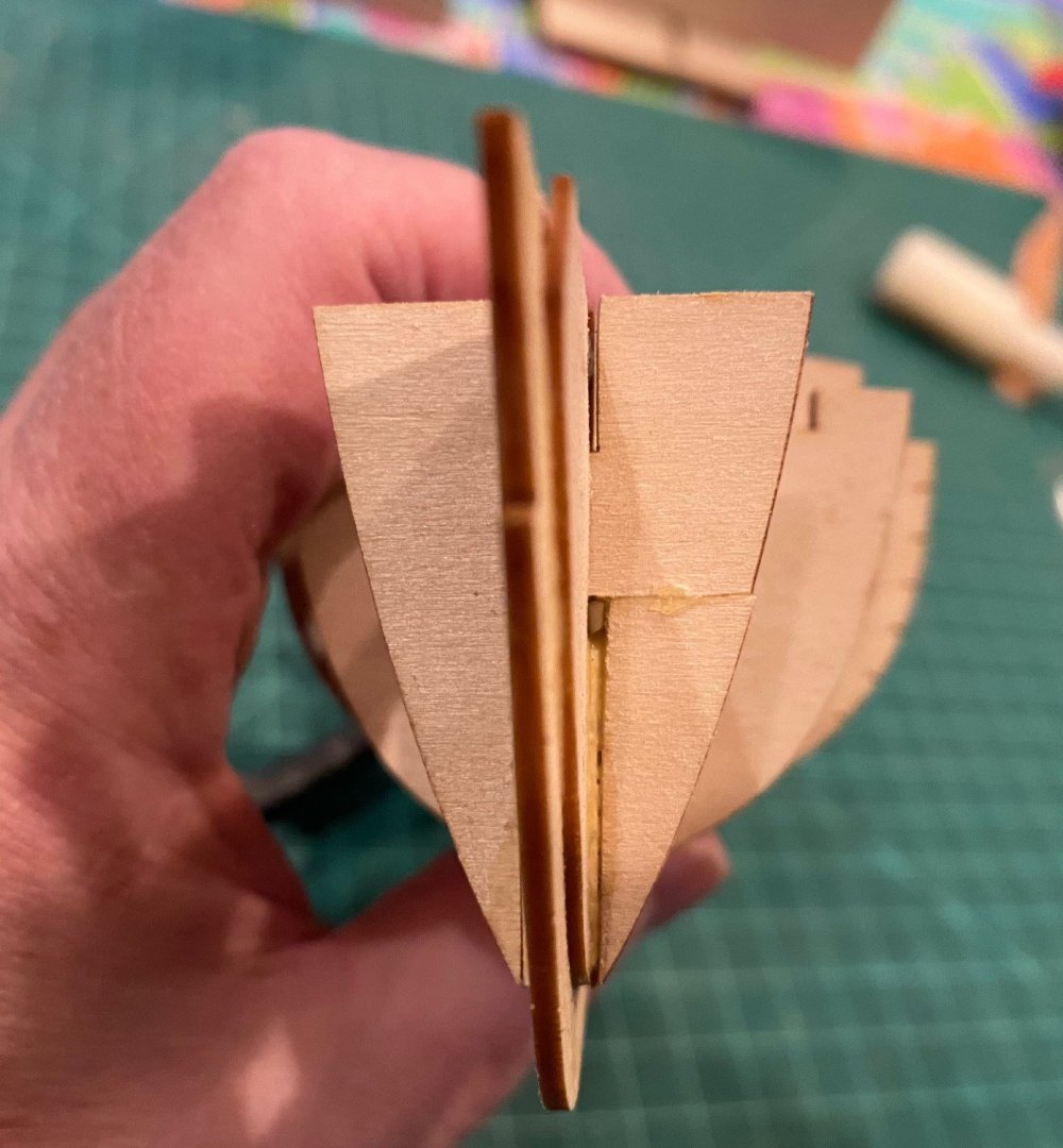
Have been exchanging emails and photos with Model Expo over the past number of days. The parts manager built a pre-production version of the Lobster Smack and did not have the problems I did, all his frames fit fine. Below is a pic of his left-over laser sheet from the frames, he said it resulted in a frame gap of 5/32 and it fit ‘OK’. Below are pic’s of some of my frames, I put them back into the laser sheet. You can see that I measure 3/16 inch, which resulted in a 1/16 inch total gap. He did say that the frames should fit next to the spine without a gap. Model Expo did offer to send me new sheets but he was not been able to measure the current gap width at this time, so I decided to just shim the frames with some left over 1/32 inch strips. I glued some 1/32 inch strips to the spine then glued frames 3, 4 and 5. The shims worked great and the cutout adjustment that I made on frame 4 worked out just a good. So, I’m moving on.


- 62 replies
-
- 5
-
-
- muscongus bay lobster smack
- Finished
- (and 1 more)
-
@JohnN THANKS for the input, I was going to do what you recommended with some left over 1/32 in strips, but I wanted to hear from Model Shipways if the frames are suppose to be gapped at the bottom or not. I also thought about reducing reinforcing piece B, but I was concerned if there was a reason it was the width it was or not. @jlefever THANKS for info, I knew I should have bought a pair of 'jeweler's' needle nose pliers.
- 62 replies
-
- 2
-
-
- muscongus bay lobster smack
- Finished
- (and 1 more)
-
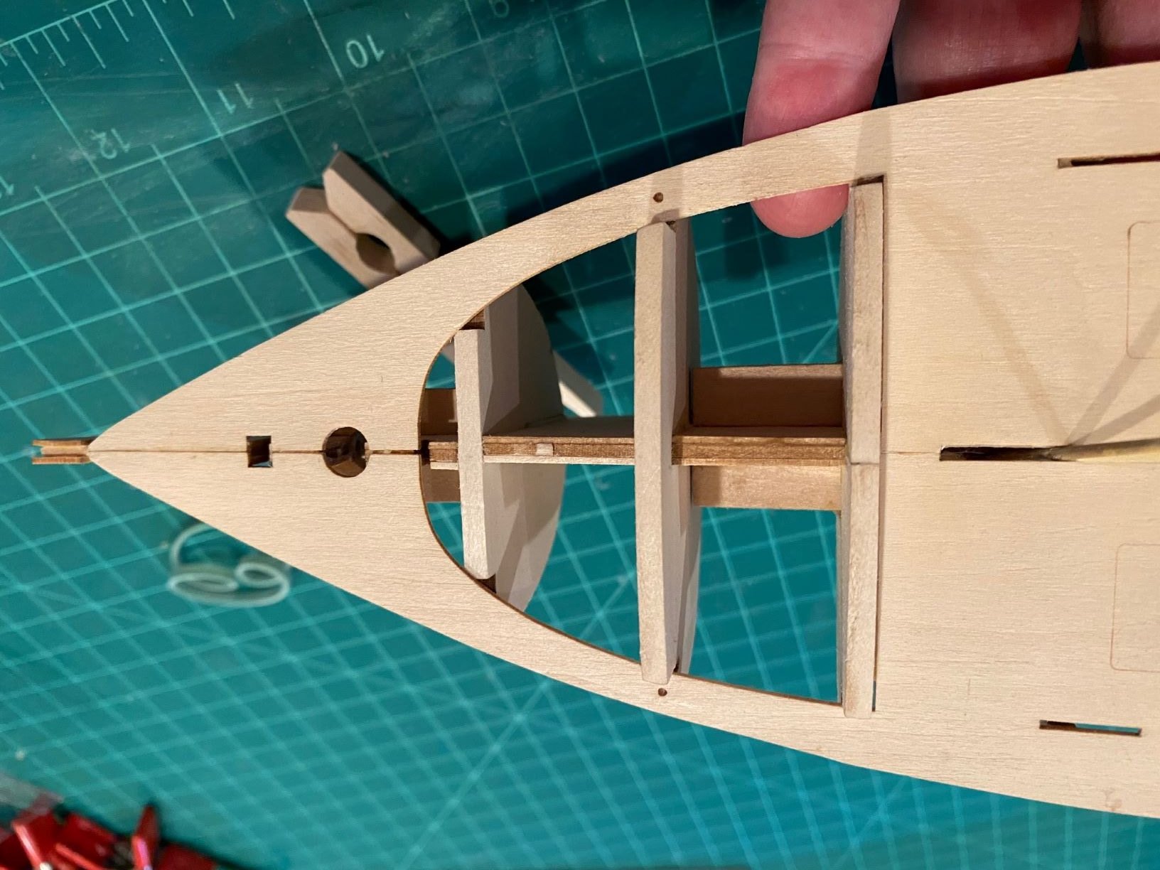
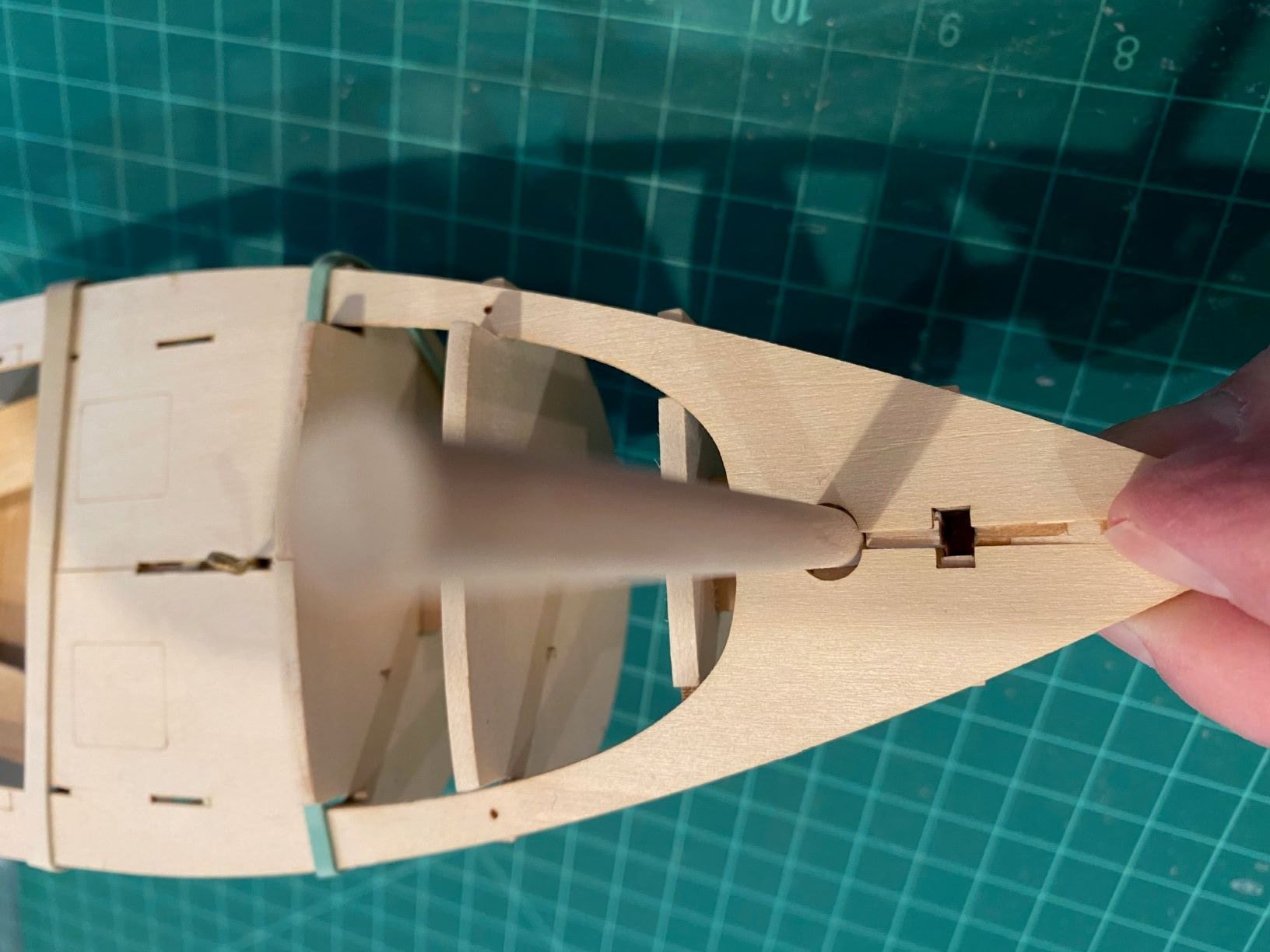
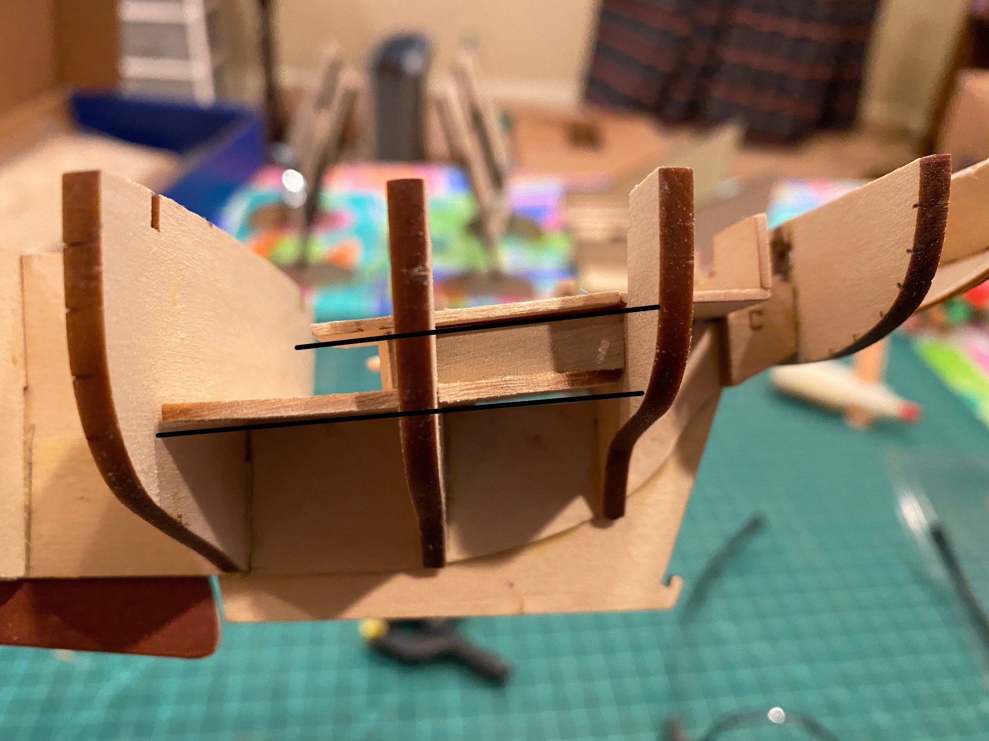
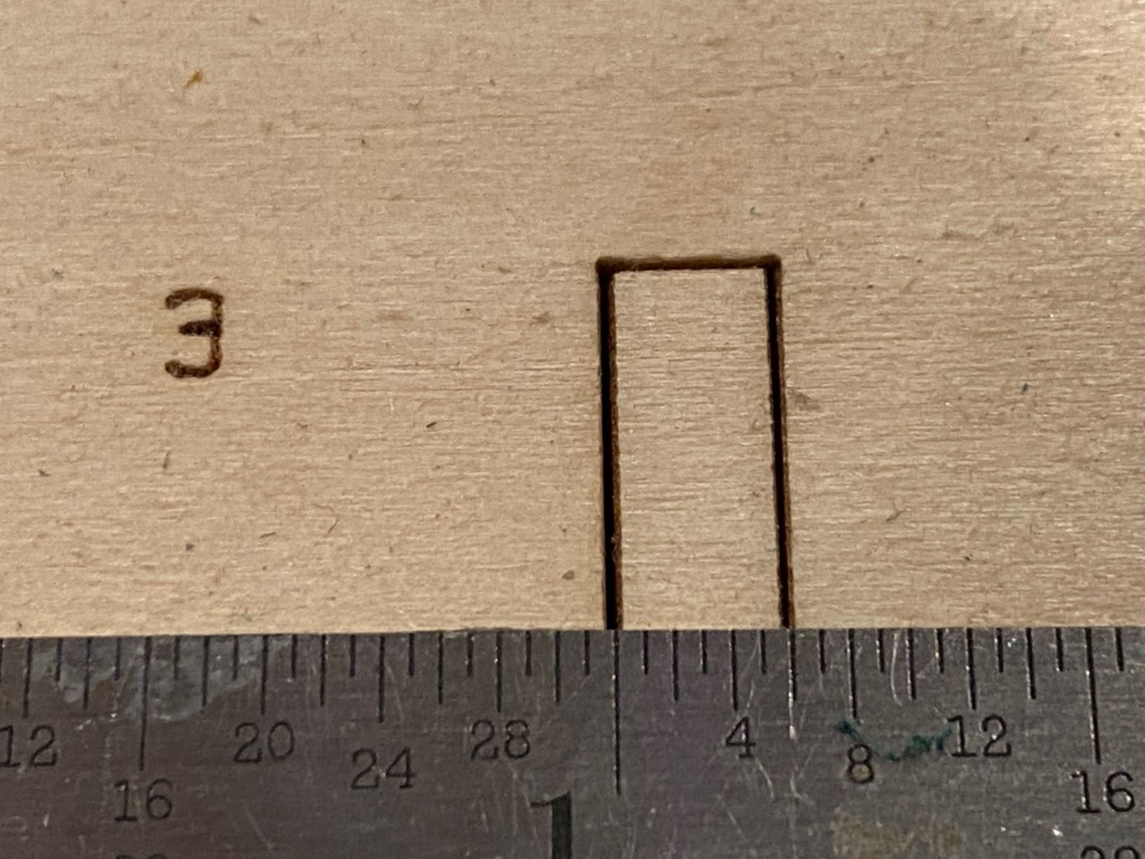
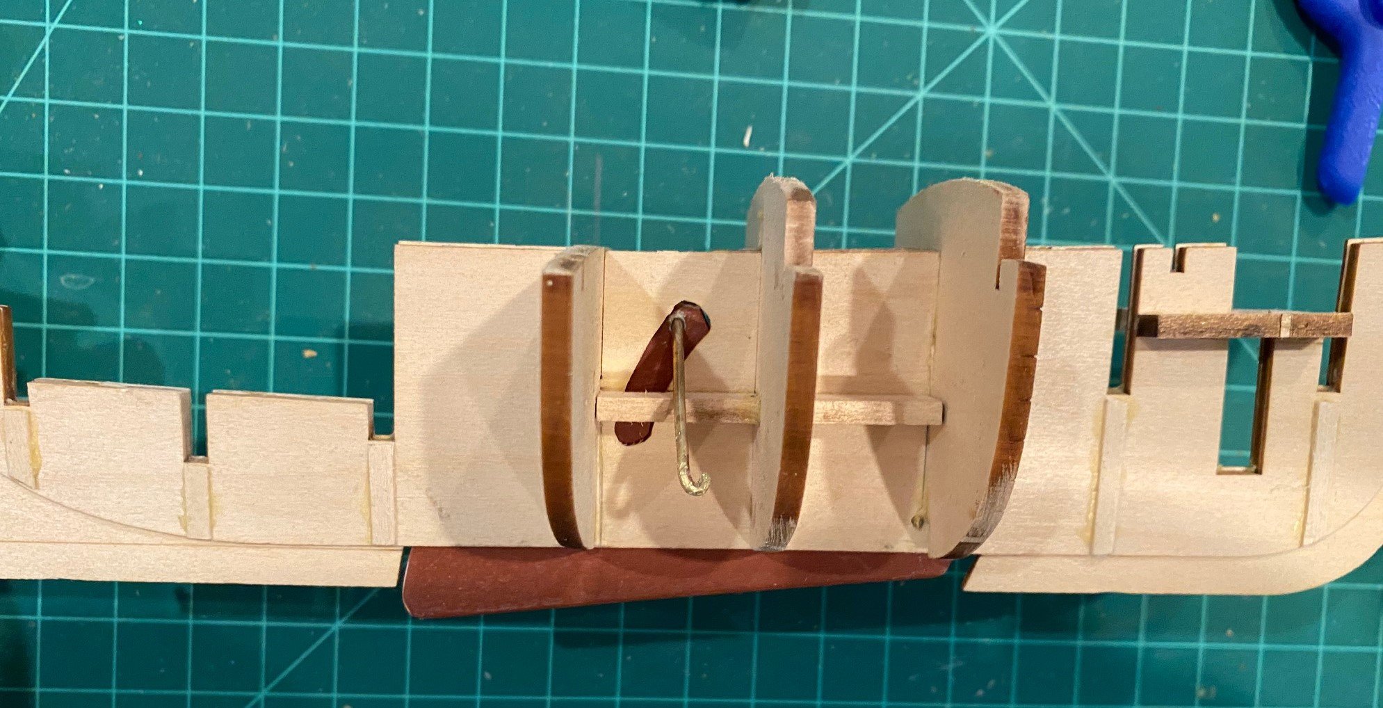
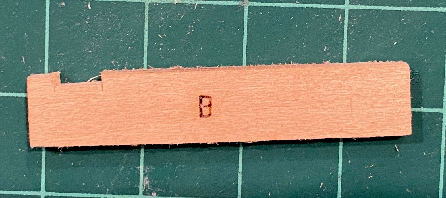
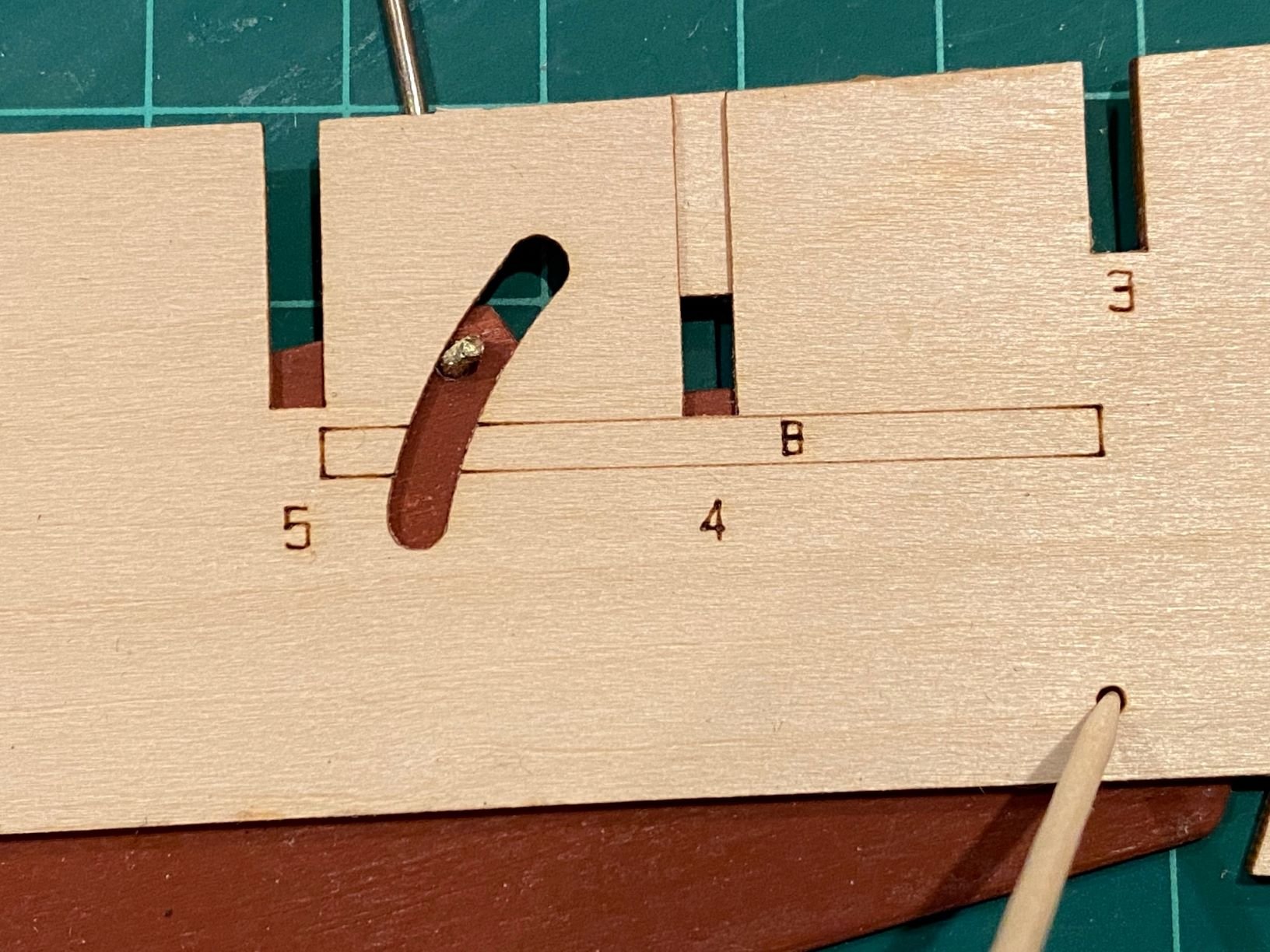
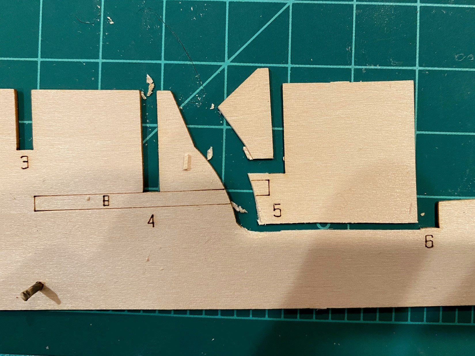
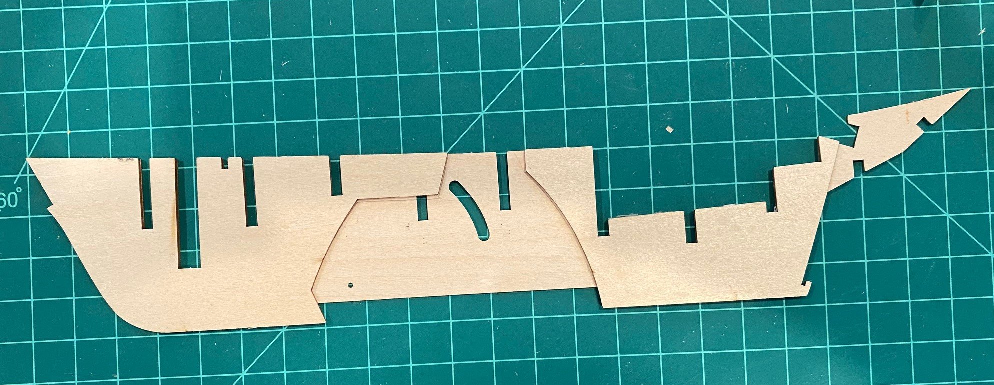
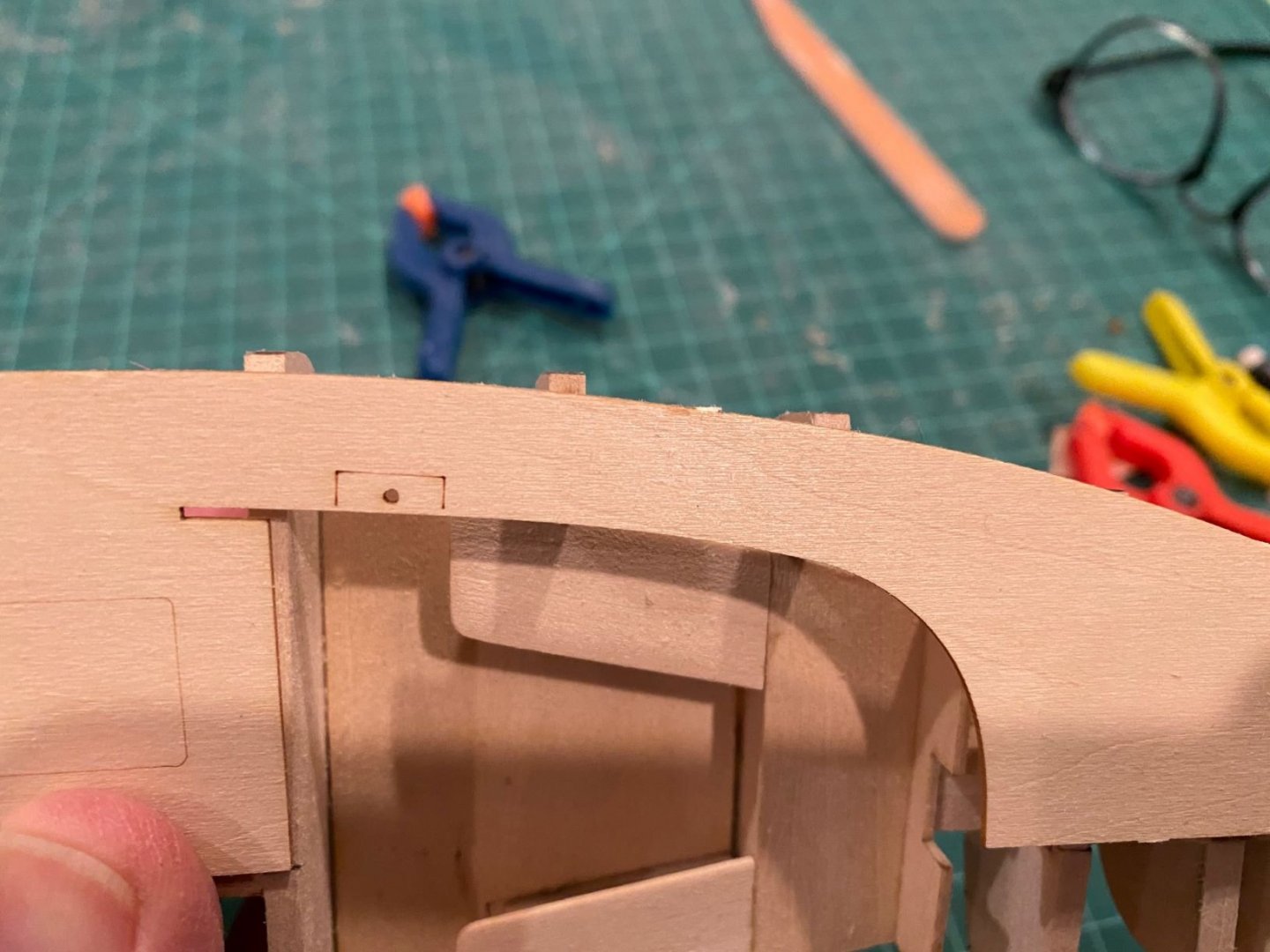
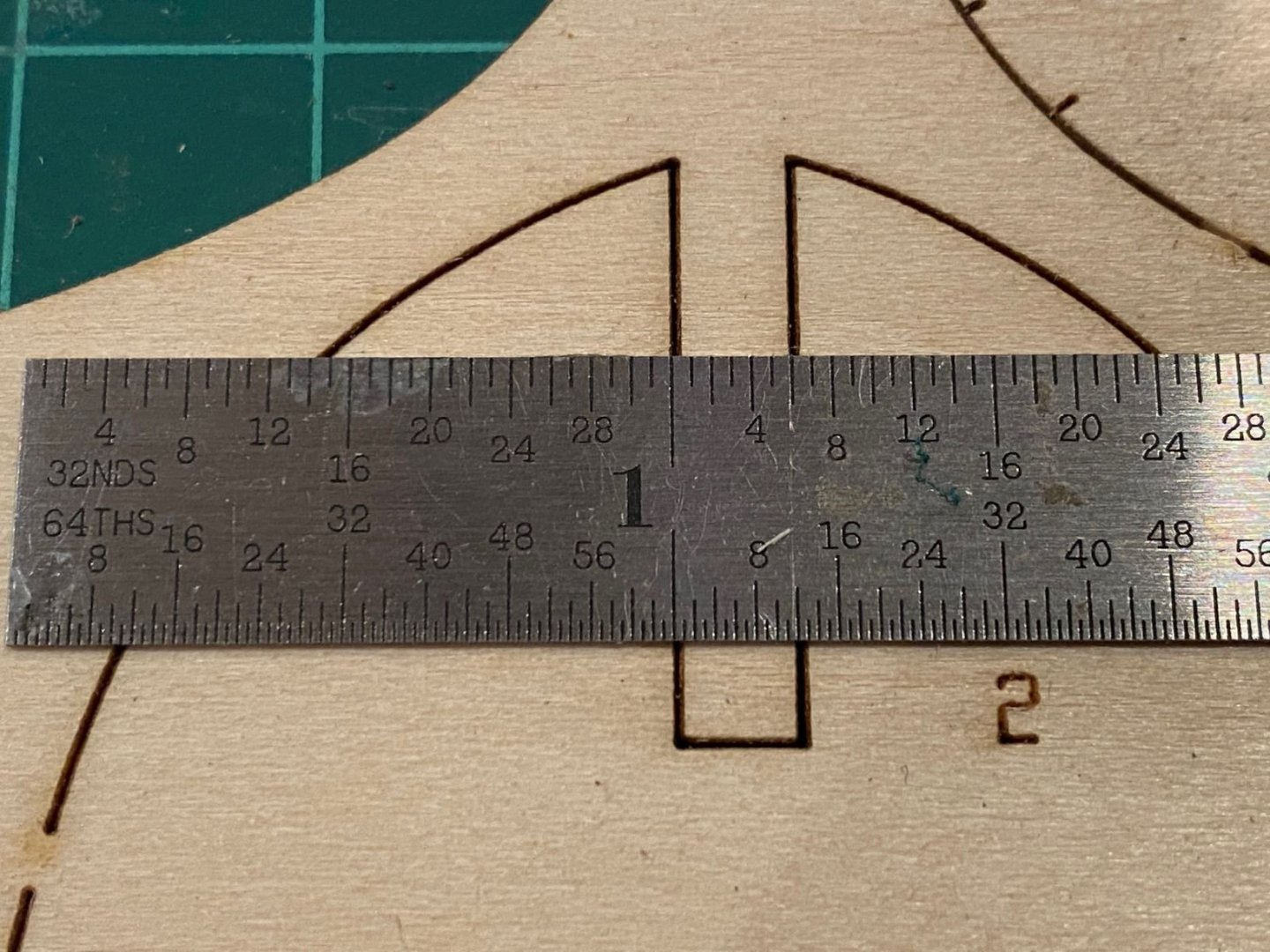
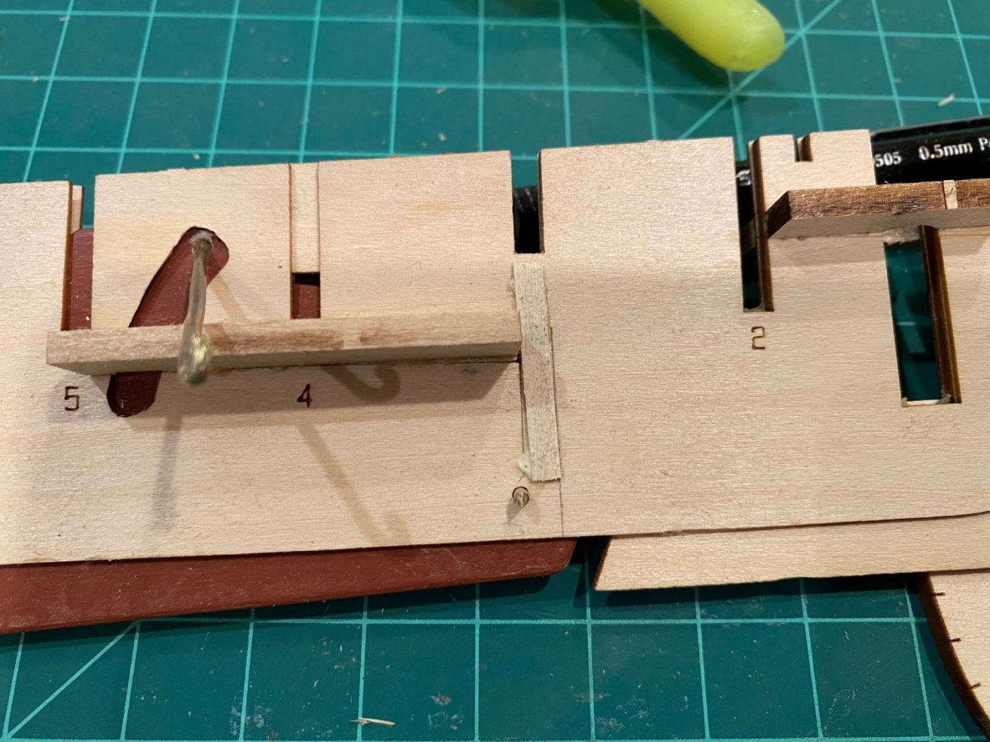
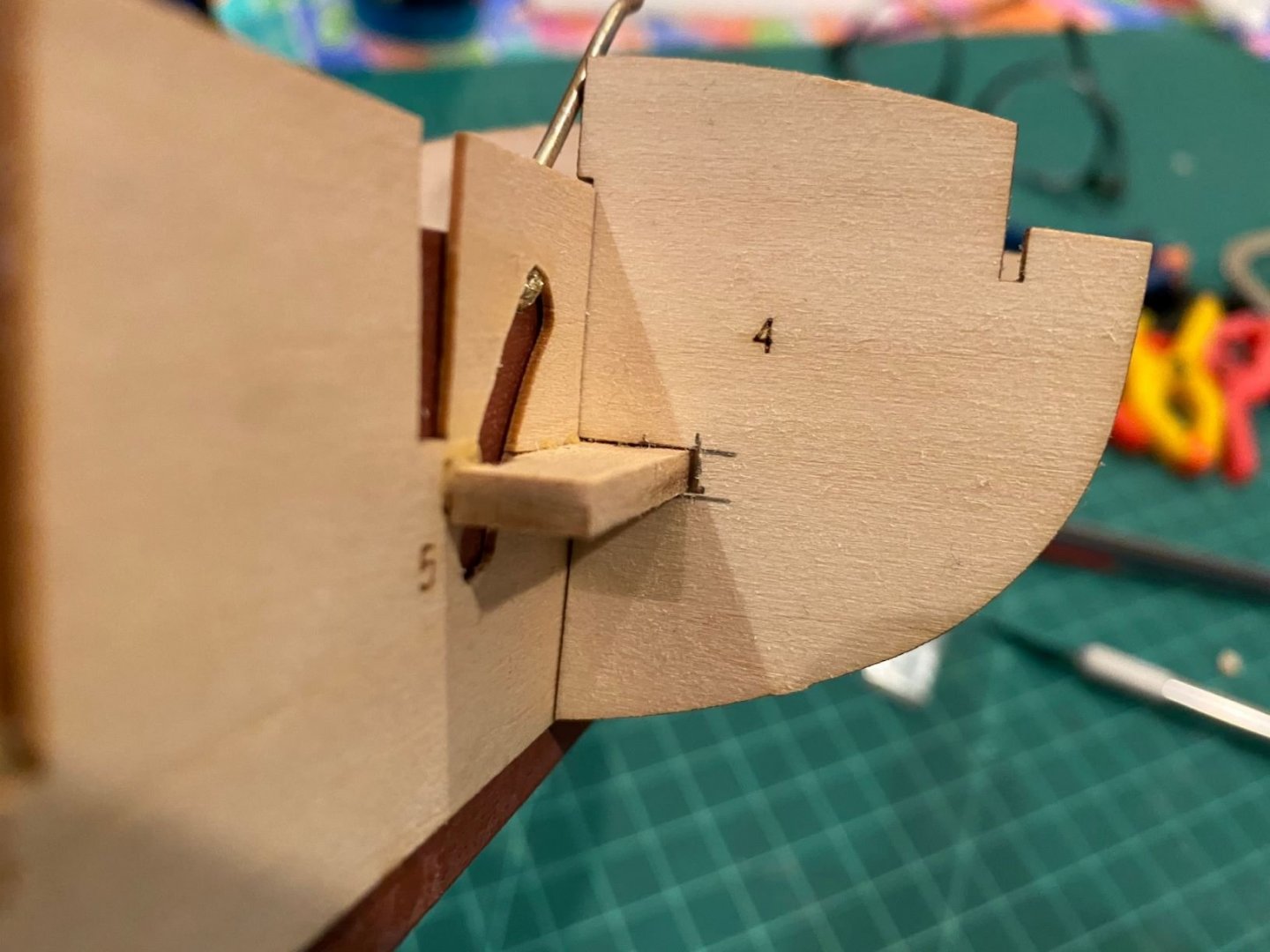
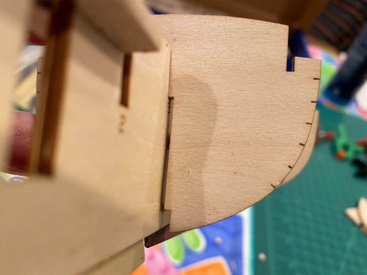
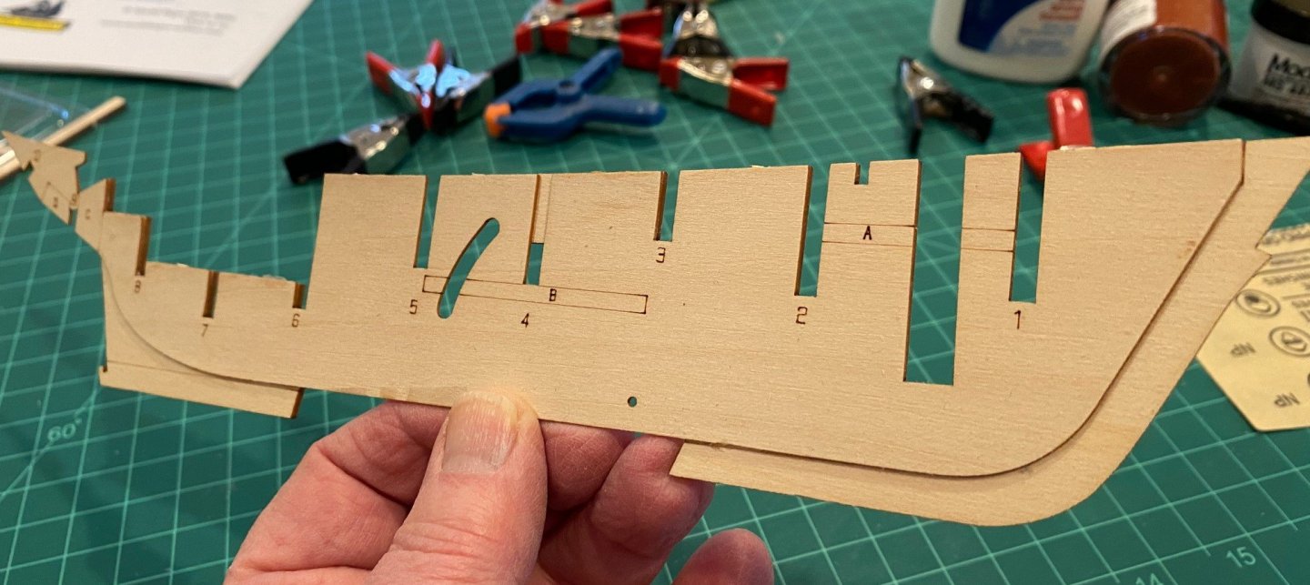
Bulkhead Frames The only problem with gluing the reinforcing pieces was the ‘B’ piece on the starboard side interfered with the hook of the brass rod at the center board which prevented the full operation of raising and lowering the center board. So I had to cut out a 1/16 inch notch in the ‘B’ reinforcing piece. It took some time and looking at all the pictures in the instructions to identify the bulkhead frames. The etched numbers were missing on some of the bulkheads. If the instructions included a scale diagram of the model frame like many other models, it would solve a lot of wasted time figuring out how parts go together. I had the same issue with the Norwegian Sailing Pram. Bulkhead Frame #4 problem; as you can see in the below picture, the notch pre-cut into Frame #4 was not deep enough to go over the ‘B’ reinforcing piece. I had to deepen the notch by 3/16 inch, I used a jeweler saw and knife for this. As I was dry fitting frame #4, the top of the frame prevented the center board from coming completely up, not sure this is a problem once the keel pieces are glue on the model. The next problem I noted when dry fitting bulkhead frames #3 and 5, is the bottom cutout is wider than the spines. The 3 parts of the spine are 1/8 inch thick when glued together, however the cutout in the frames is 3/16 inch wide so the frames don’t touch the spine in this area. I looked at all the pictures in the instructions and it looks like the frames are supposed to touch the spine in this area. Since there is no clear picture of these frames, I don’t know if there really is a problem. I’m concerned that the bottom of the frames will float until the planks are installed. Again, a to scale schematic of the model would answer this question. I sent Model Expo a question on the fit, will wait to see what they say.


- 62 replies
-
- 8
-
-
- muscongus bay lobster smack
- Finished
- (and 1 more)
-
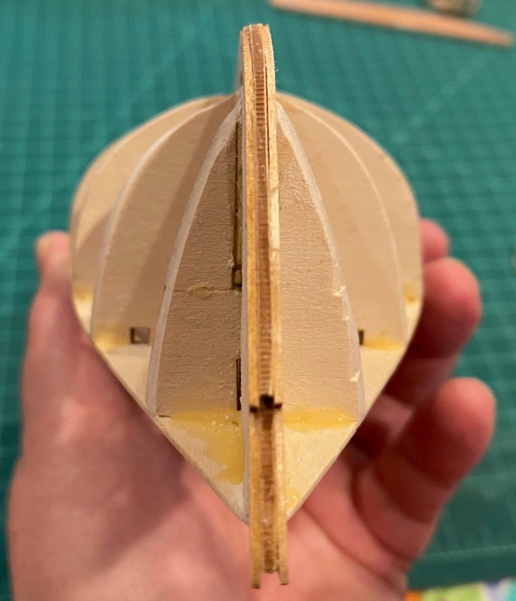
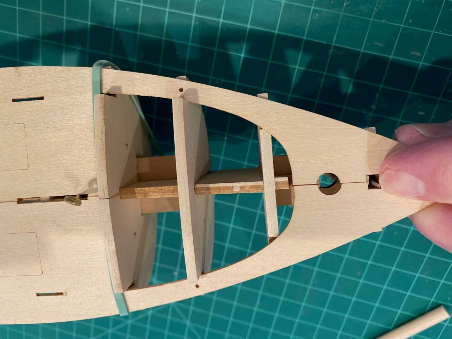
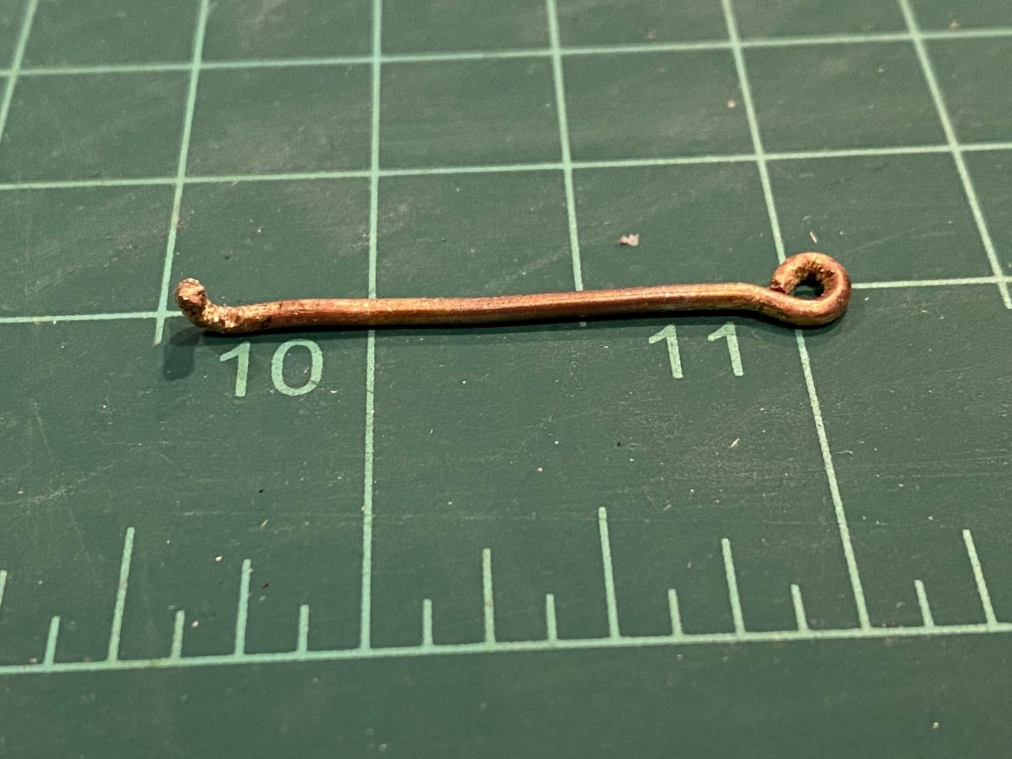
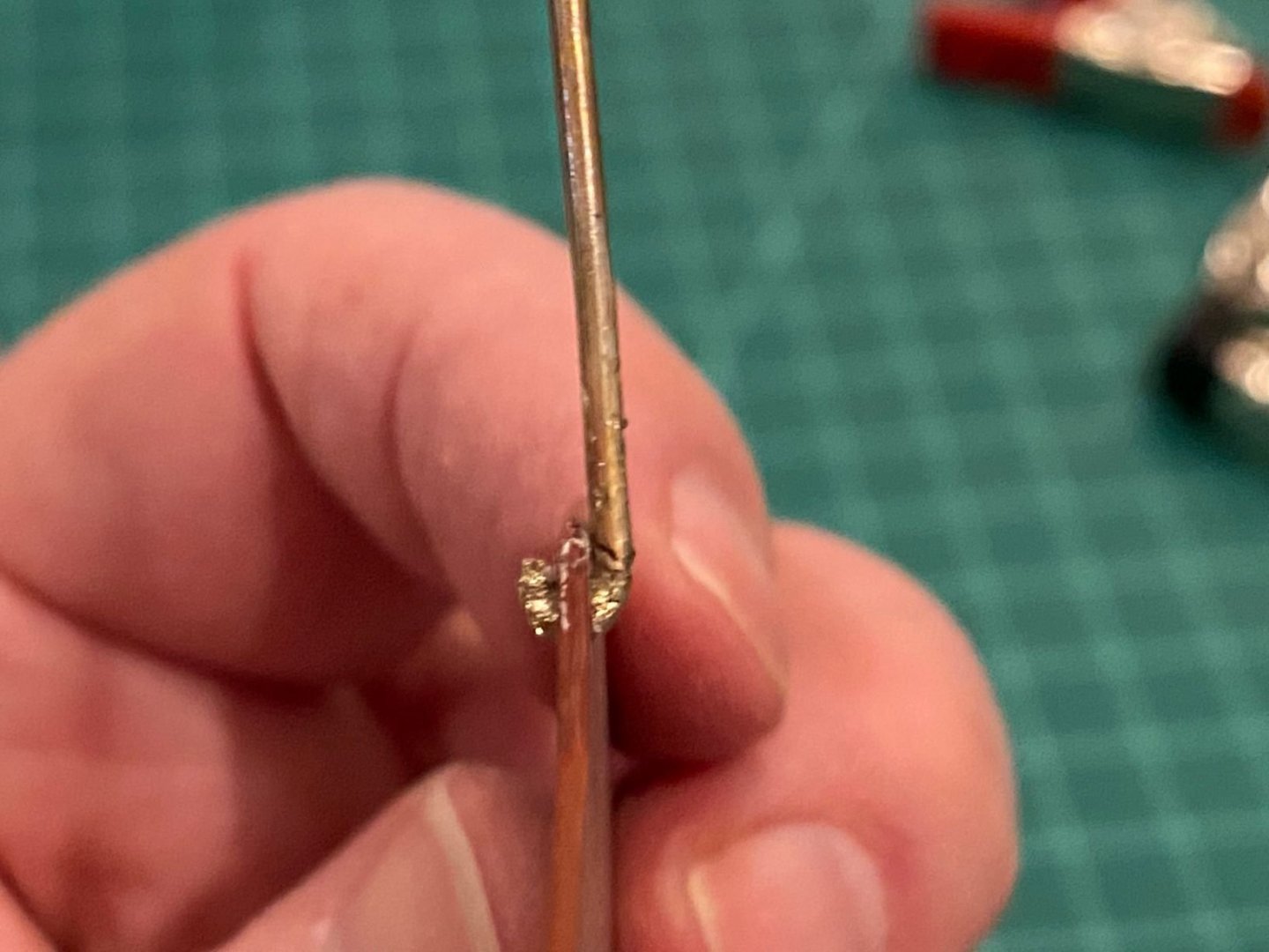
I tried to bend the brass bar without annealing it first, did not work at all well, so I went and bought a micro-torch. Heated the brass bar up on an old ceramic tile which worked very well to insulate and prevent damage to anything else. The bar now bends well. I am finding out that my small needle nose pliers do not have small enough tips for this small kind of work. My initial effort to make the eye resulted in to small of an eyelet to insert a tooth pick as a handle, so I had to pry it open and make it bigger. Finding out that you should only heat up the amount of rod that you will need to work with. As I was making the eyelet, I kept bending the rest of the bar. As I test fitted the brass arm with the center board and then the spine, I noticed that there was a major interference with the slot that the brass arm was to travel in. I chose to cut it open more with a knife to hopefully prevent breaking the thin spine. No luck, broke two parts off on the Port side spine and one part on the Starboard spine, glued them back on and waited. I tried the fit again and found out that I needed to remove more wood, ended opening up the slot by about a good 1/8 inch. Now that I did that, I noticed that the end of the brass rod that fits in the little hole of the center board needed a little more hook than being a straight elbow. Was afraid to try and bend it while it was in the center board due to the thinness of the center board wood. So, I removed it from the board and bent just a little more hook in the rod end, and very very carefully inserted it back into the board. Note that I painted the center board prior to gluing the spines together, I couldn’t see how I could get a good paint job on the board while it was assembled. I think this was a good idea. Glued the Port spine on the other spines and trapping the center board. Seems like my wood glue was a little two watery since the port spine started to curl. It was a challenge to get the spine correctly placed before the glue was too tacky. Broke off another two pieces during this process. CAUTION: the port and starboard spines a very thin and easily break.


- 62 replies
-
- 7
-
-
- muscongus bay lobster smack
- Finished
- (and 1 more)
-
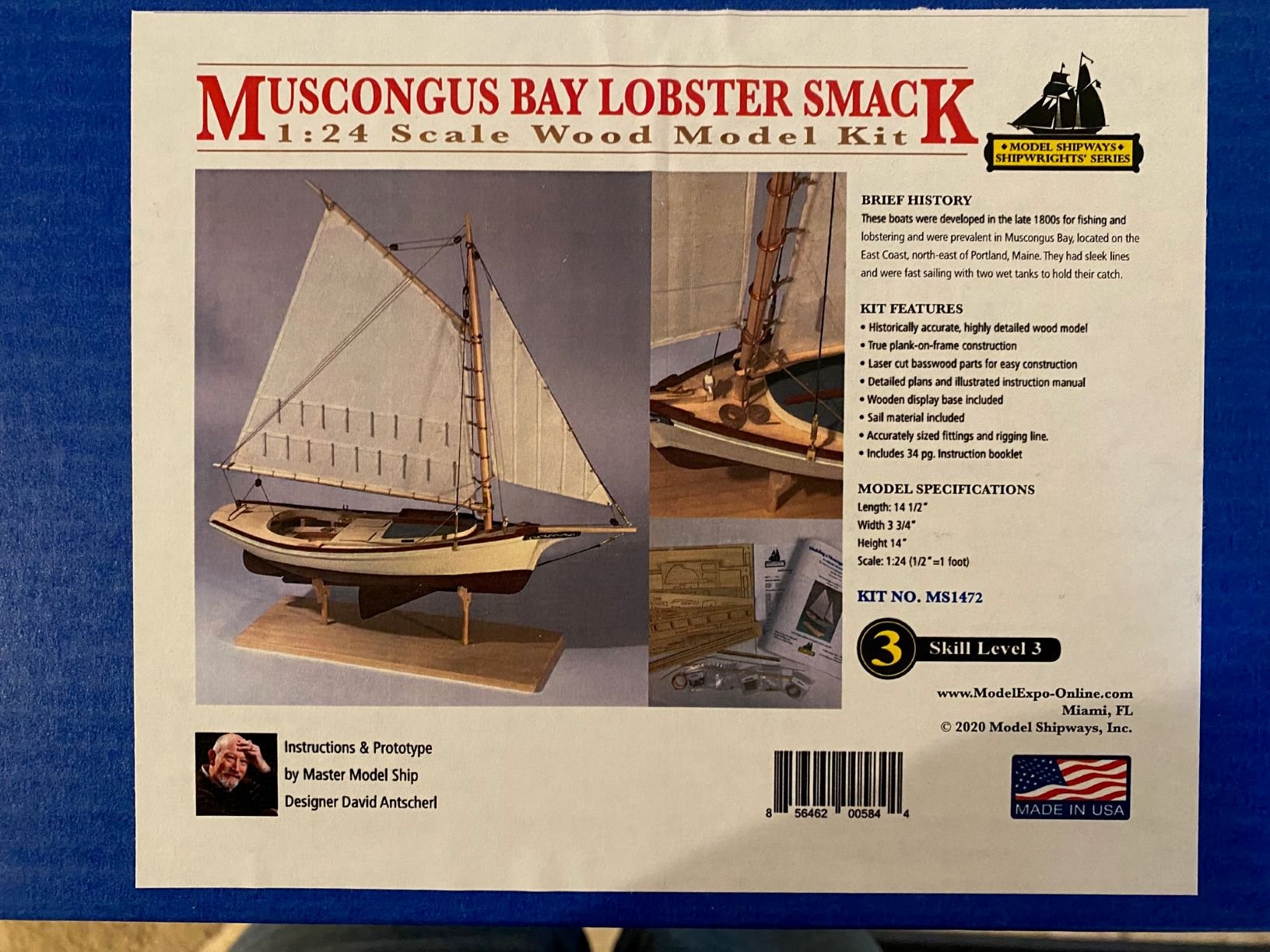
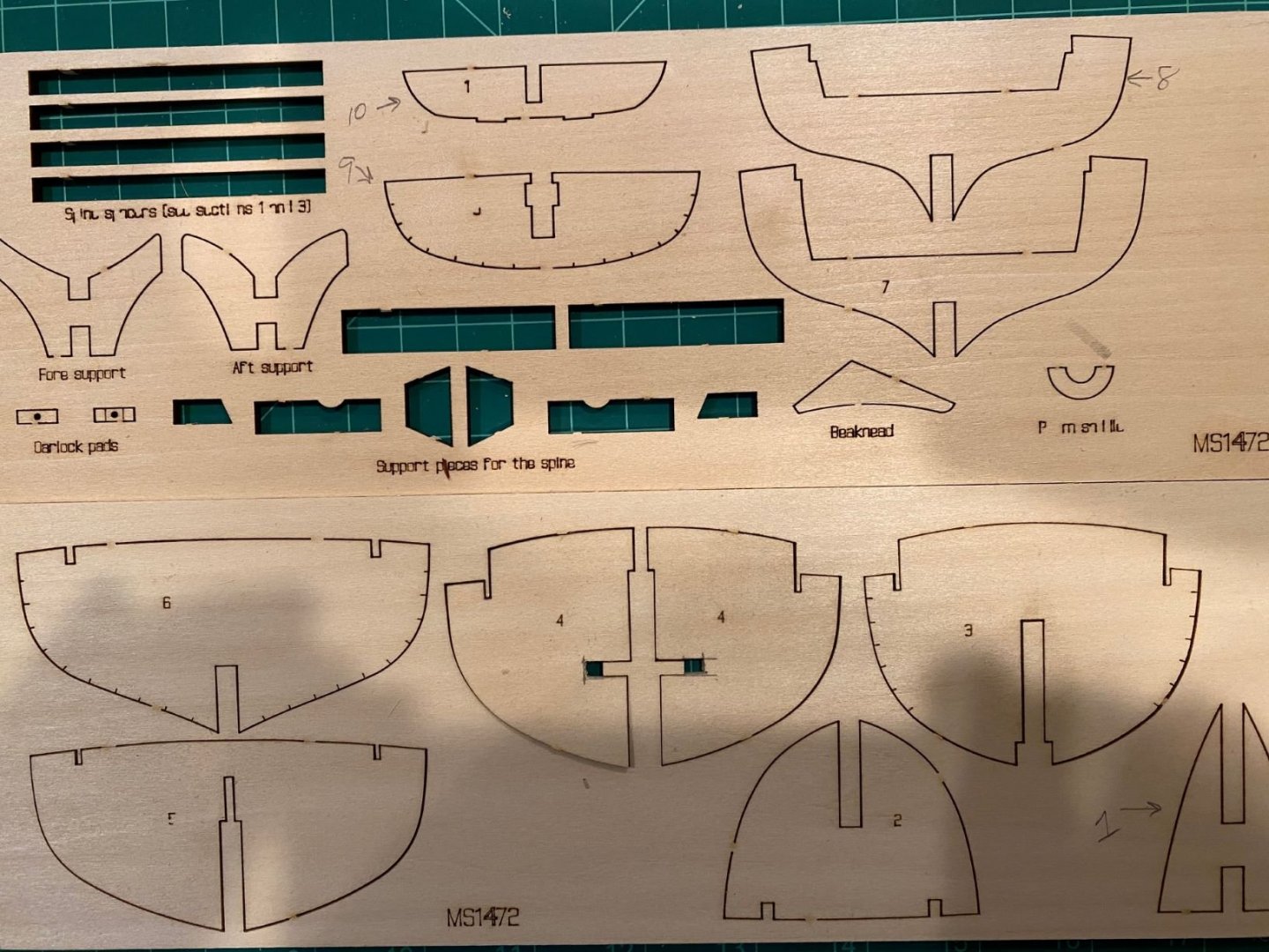
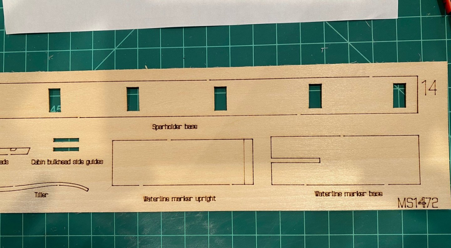
As I was finishing up the MS 18th Century Longboat, I noticed that the “third in a series of progressive model tutorials” by David Antscherl became available. My first build was the MS ‘Lowell Grand Banks Dory’ and it was a great learning experience. Then I built the MS ‘Norwegian Sailing Pram’ which was the second model in the series, it to was a great learning tool. So now I’m going to try the Muscongus Bay Lobster Smack based on a positive experience with the first two of the tutorial series. I inventoried the contents of the box and all of the parts appear to be there, except that the two ‘Cabin Bulkhead side guides’ were missing from the sheet. It looks like they might have fell during processing the kit and bagging the laser cut sheets. I think I will be able to make the parts from the left over stock since they are simple. Also, sheet 8 was labeled sheet 7. Spine & Centerboard Instructions Step 1 says to start with the Starboard Spine piece and the three center spine pieces. It calls out sheet 1, 2, 3 but sheet 2 has the Port Spine piece which confused me for a few minutes since I wasn’t sure if I should use the Port or Starboard spine piece. Looking at both the Port and Starboard (sheet 5 not 2) spine pieces and the picture on page 4, I confirmed that I should use the Starboard spine piece on sheet 5, this way the laser markings for the future bulkhead pieces was on the outside of the spine. The red sheet call out for Step 1 of the instructions should reference Sheets 1, 3, 5. The starboard spine and center spine pieces glued up nicely, I did use clamps to hold them together while the glue set instead of a weight as the instructions suggests.


- 62 replies
-
- 7
-
-
- muscongus bay lobster smack
- Finished
- (and 1 more)
-
I started to reduce the keel to 1/8 inch thick but I wanted to check midship template to see how much I should remove around the keel. However, I noticed a problem, there was a gap on the starboard side when I held the template centered on the top and bottom centerline. The gap between the side of the hull and the template was a little more than a 1/16 inch. Also, there was a gap between the top of the hull and the template a little less than a 1/16 inch. The port side was a fair match to the template. I measured the beam at midship and it matches the plans. I can’t move the keel centerline to the starboard since there is not enough material. Has anyone had a similar problem and what did you do?

-
So, I’m going to try my hand at a solid hull, it’s a little scary since I’m not a very good whittler. About 20 years ago I bought a wooden boat model that was a solid hull and I could never get it started since I had no clue on how to finish the hull. This is actually the second model I bought, but I kept putting off to gain more overall experience by building the MS Grand Banks Dory, Norwegian Pram and the 18th Century Longboat. Reading build logs about this boat made it a little less intimidating so here it goes. I have learned that it is important to inventory all the parts of a kit at the very beginning and it appears that there a couple of metal parts missing so I’ll contact Model Expo. As some of the instructions say, inventorying the parts also helps to familiarize you with them, their names and where they are installed. {I've edited the initial posting to remove the work I did on my original hull}
-
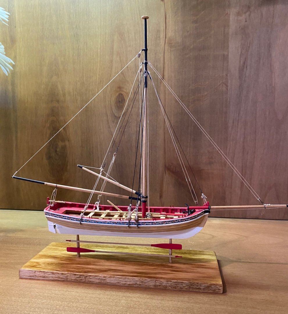
Finished, I did enjoy this build and learned a lot about planking and rigging. I am glad that I built the Grand Banks Dory and the Norwegian Pram prior to this boat, but it is a good third boat to build since you learn additional skills in planking and rigging. It was not easy for a novice but well worth the challenge. My biggest challenge was working with the small size with by fat and clumsy fingers especially rigging and tying knots. Thanks to all for your comments and suggestions, they did help, please keep it up especially for us beginners. I’m torn to start as my next build the New York Phantom Pilot Boat or the new MS Muscongus Bay Lobster Smack, the third in the learning series by David Antscherl. I’m very intimidated by carving a solid hull vs planking.


- 34 replies
-
- 8
-
-
- model shipways
- 18th century longboat
- (and 1 more)
-
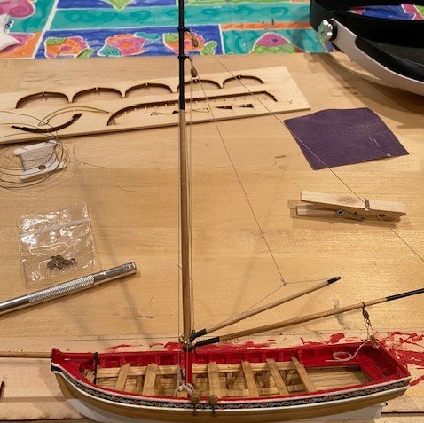
@Nirvana ; I appreciate and agree that we our own worst critics. But, I want to learn how to do better at rigging, I've read information on planking and general model boat building but have not found any information on rigging. If you know of any source please let me know. Does anyone have a reference to a blog thread or any other reference on methods to terminate ship model lines?
-
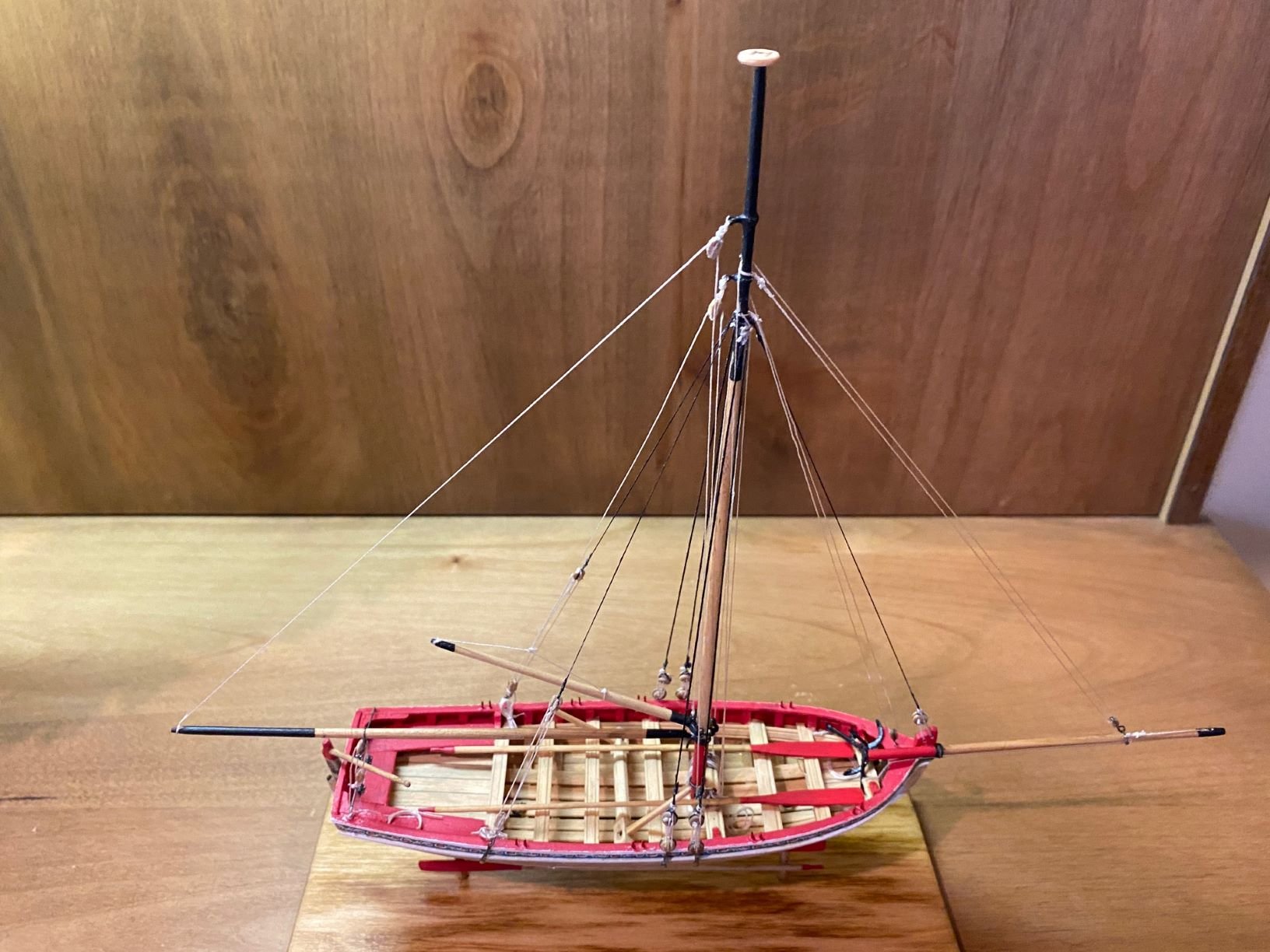
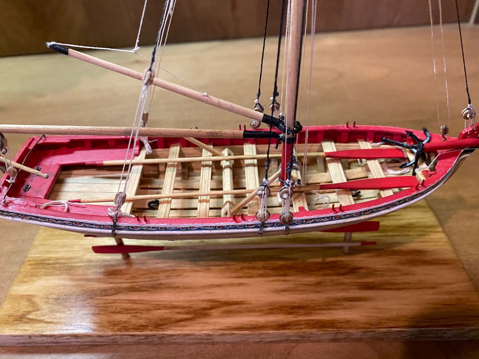
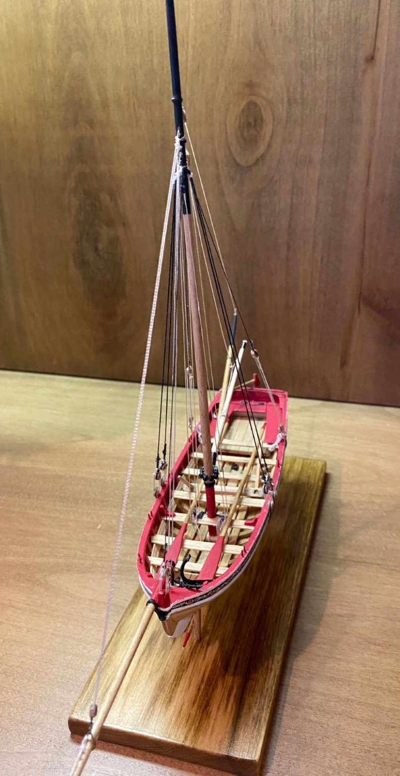
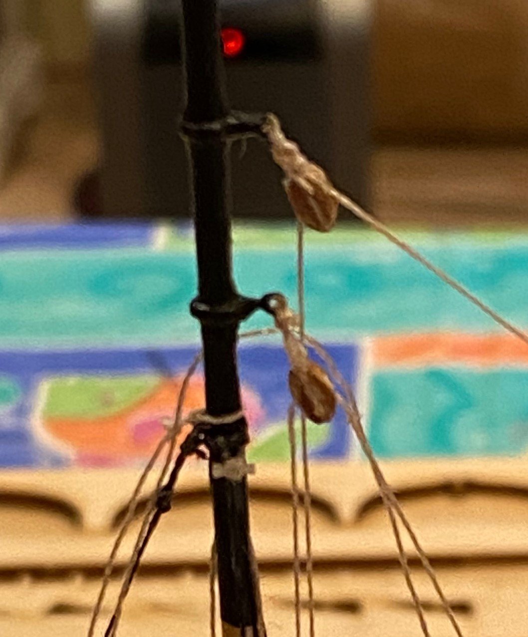
I’m proceeding with the rigging of the Longboat; it is a lot harder than the Norwegian Pram since the lines are so thin. I’m having problems with seizing the ends of the lines, they don’t look like a real line termination, just some ratty knots. Does anyone have a reference to a blog thread or any other reference on methods to terminate ship model lines?


-
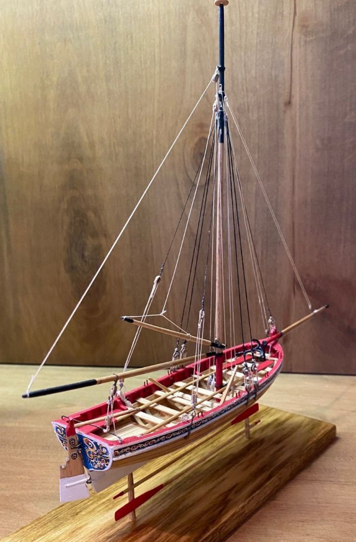
So I'm back to working the Longboat since I finished the Norwegian Pram. It was a good learning experience, especially for the rigging which was simple but a great first try at rigging. So I have the mast installed and spars installed and some rigging done. The rigging has been a challenged but it's another good learning experience. Suggestions always welcome.
- 34 replies
-
- 4
-
-
- model shipways
- 18th century longboat
- (and 1 more)
-
Great pintels, I painted my oar locks and hooks with some Testors copper, it’s what I had
-
Your build looks amazing, so much better then mine. Had the same problem with the instructions.
-
JohnN - I used Minwax pre-stain then I used Minwax Golden Oak, I wiped it off fairly soon after I applied it. I did practice on the bottom of some thwarts.
- 43 replies
-
- 1
-
-
- Norwegian Sailing Pram
- Model Shipways
- (and 1 more)
-
Fantastic job planking the port side!!!!!!!!!!!!!! Your planks came out right on the line. Keep up the great work.
-
bthoe - Thanks Don't disagree with your assessment, I did learn a lot from this second in a series build. A number of issues are those with an initial issue (beta version), such as the different parts list and missing parts, plank bevel lines, and such. That is were the strength of build logs come in, to help other builders with issues we find and/or recommendations. However, I don't think some of my frustrations could have easily been taken care of with a to scale drawing. Keep on building
- 54 replies
-
- 1
-
-
- norwegian sailing pram
- model shipways
- (and 1 more)