


jackieofalltrades
-
Posts
35 -
Joined
-
Last visited
Content Type
Profiles
Forums
Gallery
Events
Posts posted by jackieofalltrades
-
-
-
-
23 hours ago, wefalck said:
Not sure, I understand the problem well. There are three basic types of locks:
- the kind of box that is screwed to the inside of a door and the latch runs into a U-shaped part that is screwed to the door-frame - my father used to call this cow-shed lock
")
- the traditional style, where the box-shaped lock slides into a mortice in the door and is screwed down to the narrow side of the door, for which purpose the box has longer flat piece of metal attached to its narrow side; the latch runs into mortice in the frame that is re-enforced with a metal plate
- the zylindrical security locks that a set into a bore of the door and the latch runs again into a mortice in the door frame.
So what do you actually want to model ? The whole lock with its mechanism ?
I'm thinking that the best option is to make it as a full mortise lock; yes the vintage ones where the whole device slides into the slim side of the door and inc the mechanism for the handle as well.
Some of those are rim locks - where the lock itself slides into the box or the door knob itself but i think that's just too far...
I'd just have a single lever mechanism for the knob and put the keyhole beside the knob but still inside the same box/case. The key won't really be 'keyed but the lock should lock when the key is rotated manually.
I've got a few patent drawings but they are WAY more complicated than what I want bit it's harder than I thought to simplify since some of the bits do multiple things within the case.
-
-
On 9/29/2020 at 1:29 PM, druxey said:
You may need to engineer a mechanism to work at that scale; a simplification of a full-sized latch, but with the correct external appearance.
yeah, was hoping to springboard off someone else's idea but it appears that no one has done it b4 or at least they haven't publicized it.. LOL.
I really wish I already knew Fusion.
thx!
-
-
-
Looking for directions, plans, schematics for modelling primarily locks mortise types for doors or General latches. Would like to construct in styrene first and non-ferrous Metals afterwards.
I tried looking at patents but they were all very complicated and I got lost in the level of detail.
Then I tried YouTube videos of people restoring mortise locks but I could never get a clear enough you of all of the parts of any particular lock.
Lastly, I even tried lockpicking books and sites but they all focus on the actual process of picking locks and never the mortise style just the knobs...LOL
In a perfect world I'd like to model working ( functional)
door knobs and locks & window latches of any style
Any pioneers or suggestions?
-
I have this book if I'm not too late
https://books.google.com/books/about/Patina.html?id=ZiNjDwAAQBAJ
-
I'm a guillotine girl for my copper & brass to .5mm & under. Will have to try the stainless shim I have on it too!
- mtaylor, thibaultron and Canute
-
 3
3
-
Thanks all for the warm welcome. I'm a scrstch builder so I don't know about u but btw that and multiple mediums, (& a disability or two) it means that things take me a painfully long time lol.
I hope it doesn't matter that the vessel I want to model is super simple. Not a warship or schooner or anything more than the houseboat we spent a month on when I was a teen
I tend to model either memories or gifts..
-
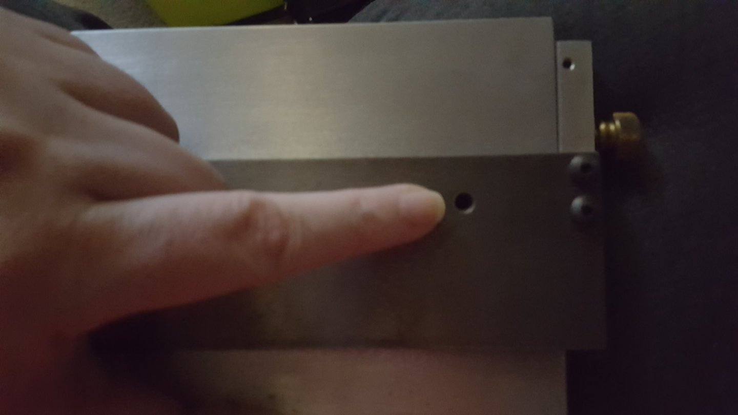
so does anyone want to weigh in on what the two holes that go through the table and it's fence are for?
- thibaultron, mtaylor, Archi and 1 other
-
4
-
Hey all not sure how many members are Canadian let alone women but here I am.
I work in a lot of different scales but started primarily 1:12 dollhousing.
Mostly I love that it lets me work in multiple mediums from PE, wood, styrene and even electronics!
mostly right now I'm raring to go with the first run of photo etch but first I have to get my desktop rebuilt since I'm short the artwork! so frustrating to be so close...
Anyways, that's me in a nutshell. Hi to you all!
- Duanelaker, JeffT, Edwardkenway and 5 others
-
8
-
1 hour ago, Jaager said:
If the object is to be able to get a precise and reproducible saw tilt and this will be done frequently with multiple possible angles being cut:
Fix the machine to a two plywood sheet base.
Lower is a 1/2" - 3/4" sheet. width 3" or more wider than saw base on each side.
Upper is 1/4" sheet
The right edge of upper sheet is at the right side of the saw base.
The upper sheet is attached to the lower using a full size piano hinge.
The left side is as far beyond the base of the saw as is needed to fix a a threaded rod and thumb screw or wingnut to raise that edge.
There would probably need to be spacer pieces at the hinge and outer edges of the upper sheet that are a tad thicker than the thumb screw/wingnut.
Someone really OCD could fix the angle gauge from a adjustable miter - or a stick with marks at the front right at the hinge.
The down side is that it adds weight to an already hefty machine.
A 1" rubber stopper fixed under each corner of the base will provide space for fingers to lift the machine, if it just rents bench space and lives on a shelf.
any chance of a pic...not sure if my poor brain got that properly. Using the saw this way doesn't the weight of the wood itself start to where on the little hinges that came with the accessory? Sorry for so many questions that I've been looking for 2 years for decent info. Wasn't able to find anything but a few mentions.
- Canute, mtaylor and thibaultron
-
3
-
On 7/24/2020 at 10:13 PM, Moxis said:
Very interesting. It begins to be clear that you can electroform or electroplate items relatively easily at home with copper, but us ship model builders would need parts made of, or at least look like made of brass. So I think it is not possible to apply brass surface directly on conductive paint, but you need first to electroplate the part with copper.
But how about gold plating, can it be applied directly on conductive paint? Gold plating could be perfect on small items, it will look like polished brass, never oxidize and very thin layer of gold doesn't cost very much more than plating the parts first with copper and after that with brass.
gold plating would need to be plated with nickel first
- Canute, Landlubber Mike and mtaylor
-
3
-
4 hours ago, kurtvd19 said:
One tip on using the tilt table. If the saw is kept level using the tilt table is a bit awkward. Use a couple of wedges under the saw so the tilt table is level with the bench top and it does away with the awkward working on the tilt table and the tendency for gravity to work against holding the wood against the uphill fence.
How do you adjust for different angles? I assume you have the common 45 set up and 22.5 perhaps?
I have one of the digital angle cubes that I was hoping to rig up for easier & mostly accurate setup
- Canute, mtaylor and thibaultron
-
3
-
Thank you all for the information. Trying to work it out I thought I was totally missing something. I'm a visual person so pictures of how you have yours functioning would be extra helpful. Thank you again
- thibaultron, mtaylor and Canute
-
3
-
Does anyone have information on the table top slanted extension for cutting on the table saw?
I've never been able to figure out how it's supposed to actually work LOL

Black Friday Deals for Modelers
in Modeling tools and Workshop Equipment
Posted
Anyone know of online suppliers for modeling tools or supplies that have great sales or deals on for Black Friday?