


AnobiumPunctatum
-
Posts
1,233 -
Joined
-
Last visited
Reputation Activity
-

.thumb.jpg.62d1d69fed1f32364417cb1f9cdeb009.jpg) AnobiumPunctatum got a reaction from WalrusGuy in HMS Triton 1771 by AnobiumPunctatum - scale 1/48
AnobiumPunctatum got a reaction from WalrusGuy in HMS Triton 1771 by AnobiumPunctatum - scale 1/48
Thanks for the Likes.
Today I prepared the "Knee of the Head". I have divided this one into two parts to make it easier for me to adapt to the stem later. First the chocks of the upper part were adjusted and glued together. For the caulking was again single layer cellulose used. To compensate for small tolerances, the templates were again exchanged for a single one after completion of the assembly. The main piece and the other components of the upper assembly were then added.
The lower assembly was then adapted and assembled.
The following two pictures show the current status:
Since my vacation is coming to an end, the shipyard is now being exchanged for the home office. Nevertheless I hope to finish the "Knee of the Head" next weekend.
-
 AnobiumPunctatum got a reaction from KrisWood in HMS Triton 1771 by AnobiumPunctatum - scale 1/48
Thanks for the Likes.
Today I prepared the "Knee of the Head". I have divided this one into two parts to make it easier for me to adapt to the stem later. First the chocks of the upper part were adjusted and glued together. For the caulking was again single layer cellulose used. To compensate for small tolerances, the templates were again exchanged for a single one after completion of the assembly. The main piece and the other components of the upper assembly were then added.
The lower assembly was then adapted and assembled.
The following two pictures show the current status:
Since my vacation is coming to an end, the shipyard is now being exchanged for the home office. Nevertheless I hope to finish the "Knee of the Head" next weekend.
-
AnobiumPunctatum got a reaction from WalrusGuy in HMS Triton 1771 by AnobiumPunctatum - scale 1/48
The description of my reconstruction you will find here.
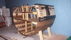
On Easter Monday the time had finally come. The keel of his majesty's frigate HMS Triton was laid.
First the 5 components for the keel were sawn out.
I have simplified the design of the joints considerably, as they will be completely covered later on by further components. I will continue to apply this principle during the further construction in order to adapt the building as far as possible to my craftsmanship.
The first cliff that had to be overcome is the joint between keel and lower stem. I worked this out with my milling machine and chisels.
After I had attached the wrong keel, the joints have to be dowelled. These dowels are a bit too big for the chosen scale, but I cannot draw pear wood thinner than 0.8 mm. I know that many modellers swear by bamboo, but I find pear on the finished model more discreet.
I have simulated the caulking with single-ply pulp.
-
 AnobiumPunctatum got a reaction from Dubz in HMS Triton 1771 by AnobiumPunctatum - scale 1/48
Thanks for the Likes.
Today I prepared the "Knee of the Head". I have divided this one into two parts to make it easier for me to adapt to the stem later. First the chocks of the upper part were adjusted and glued together. For the caulking was again single layer cellulose used. To compensate for small tolerances, the templates were again exchanged for a single one after completion of the assembly. The main piece and the other components of the upper assembly were then added.
The lower assembly was then adapted and assembled.
The following two pictures show the current status:
Since my vacation is coming to an end, the shipyard is now being exchanged for the home office. Nevertheless I hope to finish the "Knee of the Head" next weekend.
-
AnobiumPunctatum got a reaction from KrisWood in HMS Triton 1771 by AnobiumPunctatum - scale 1/48
Further with the "Upper stem". There are only two parts that have to be glued to the lower part of the stem, which was already shown in the last part. The issue is complicated by the fact that even tiny angular deviations in the "Joint" lead to deviations at the upper end of the component. Aggravating is the fact that the component is about 1.7mm thicker than the keel
At first I built a small jig, which fixes the keel during the adjustment work. To check the position of the components, a template was aligned on the working surface and fixed with adhesive tape. Thin wooden plates were placed under the keel to compensate for half of the height difference.
Next, the two components of the "upper stem" were glued together. A little more material was deliberately left at the sides to compensate for the construction tolerances later. Then the joint between the new component and the "Lower stem" was adjusted with my milling machine, chisels and sandpaper until the upper end of the stem was in line with the template. Now the components could be glued together.
The old templates were removed and a new template was glued and aligned. Finally, the stem was sanded into shape.
-
AnobiumPunctatum got a reaction from Dubz in HMS Triton 1771 by AnobiumPunctatum - scale 1/48
Further with the "Upper stem". There are only two parts that have to be glued to the lower part of the stem, which was already shown in the last part. The issue is complicated by the fact that even tiny angular deviations in the "Joint" lead to deviations at the upper end of the component. Aggravating is the fact that the component is about 1.7mm thicker than the keel
At first I built a small jig, which fixes the keel during the adjustment work. To check the position of the components, a template was aligned on the working surface and fixed with adhesive tape. Thin wooden plates were placed under the keel to compensate for half of the height difference.
Next, the two components of the "upper stem" were glued together. A little more material was deliberately left at the sides to compensate for the construction tolerances later. Then the joint between the new component and the "Lower stem" was adjusted with my milling machine, chisels and sandpaper until the upper end of the stem was in line with the template. Now the components could be glued together.
The old templates were removed and a new template was glued and aligned. Finally, the stem was sanded into shape.
-
AnobiumPunctatum got a reaction from KrisWood in HMS Triton 1771 by AnobiumPunctatum - scale 1/48
The description of my reconstruction you will find here.
On Easter Monday the time had finally come. The keel of his majesty's frigate HMS Triton was laid.
First the 5 components for the keel were sawn out.
I have simplified the design of the joints considerably, as they will be completely covered later on by further components. I will continue to apply this principle during the further construction in order to adapt the building as far as possible to my craftsmanship.
The first cliff that had to be overcome is the joint between keel and lower stem. I worked this out with my milling machine and chisels.
After I had attached the wrong keel, the joints have to be dowelled. These dowels are a bit too big for the chosen scale, but I cannot draw pear wood thinner than 0.8 mm. I know that many modellers swear by bamboo, but I find pear on the finished model more discreet.
I have simulated the caulking with single-ply pulp.
-
 AnobiumPunctatum got a reaction from archjofo in HMS Triton 1771 by AnobiumPunctatum - scale 1/48
Further with the "Upper stem". There are only two parts that have to be glued to the lower part of the stem, which was already shown in the last part. The issue is complicated by the fact that even tiny angular deviations in the "Joint" lead to deviations at the upper end of the component. Aggravating is the fact that the component is about 1.7mm thicker than the keel
At first I built a small jig, which fixes the keel during the adjustment work. To check the position of the components, a template was aligned on the working surface and fixed with adhesive tape. Thin wooden plates were placed under the keel to compensate for half of the height difference.
Next, the two components of the "upper stem" were glued together. A little more material was deliberately left at the sides to compensate for the construction tolerances later. Then the joint between the new component and the "Lower stem" was adjusted with my milling machine, chisels and sandpaper until the upper end of the stem was in line with the template. Now the components could be glued together.
The old templates were removed and a new template was glued and aligned. Finally, the stem was sanded into shape.
-
 AnobiumPunctatum got a reaction from druxey in HMS Triton 1771 by AnobiumPunctatum - scale 1/48
Further with the "Upper stem". There are only two parts that have to be glued to the lower part of the stem, which was already shown in the last part. The issue is complicated by the fact that even tiny angular deviations in the "Joint" lead to deviations at the upper end of the component. Aggravating is the fact that the component is about 1.7mm thicker than the keel
At first I built a small jig, which fixes the keel during the adjustment work. To check the position of the components, a template was aligned on the working surface and fixed with adhesive tape. Thin wooden plates were placed under the keel to compensate for half of the height difference.
Next, the two components of the "upper stem" were glued together. A little more material was deliberately left at the sides to compensate for the construction tolerances later. Then the joint between the new component and the "Lower stem" was adjusted with my milling machine, chisels and sandpaper until the upper end of the stem was in line with the template. Now the components could be glued together.
The old templates were removed and a new template was glued and aligned. Finally, the stem was sanded into shape.
-
 AnobiumPunctatum got a reaction from tlevine in HMS Triton 1771 by AnobiumPunctatum - scale 1/48
Further with the "Upper stem". There are only two parts that have to be glued to the lower part of the stem, which was already shown in the last part. The issue is complicated by the fact that even tiny angular deviations in the "Joint" lead to deviations at the upper end of the component. Aggravating is the fact that the component is about 1.7mm thicker than the keel
At first I built a small jig, which fixes the keel during the adjustment work. To check the position of the components, a template was aligned on the working surface and fixed with adhesive tape. Thin wooden plates were placed under the keel to compensate for half of the height difference.
Next, the two components of the "upper stem" were glued together. A little more material was deliberately left at the sides to compensate for the construction tolerances later. Then the joint between the new component and the "Lower stem" was adjusted with my milling machine, chisels and sandpaper until the upper end of the stem was in line with the template. Now the components could be glued together.
The old templates were removed and a new template was glued and aligned. Finally, the stem was sanded into shape.
-
 AnobiumPunctatum got a reaction from Siggi52 in HMS Triton 1771 by AnobiumPunctatum - scale 1/48
Further with the "Upper stem". There are only two parts that have to be glued to the lower part of the stem, which was already shown in the last part. The issue is complicated by the fact that even tiny angular deviations in the "Joint" lead to deviations at the upper end of the component. Aggravating is the fact that the component is about 1.7mm thicker than the keel
At first I built a small jig, which fixes the keel during the adjustment work. To check the position of the components, a template was aligned on the working surface and fixed with adhesive tape. Thin wooden plates were placed under the keel to compensate for half of the height difference.
Next, the two components of the "upper stem" were glued together. A little more material was deliberately left at the sides to compensate for the construction tolerances later. Then the joint between the new component and the "Lower stem" was adjusted with my milling machine, chisels and sandpaper until the upper end of the stem was in line with the template. Now the components could be glued together.
The old templates were removed and a new template was glued and aligned. Finally, the stem was sanded into shape.
-
 AnobiumPunctatum got a reaction from Edwardkenway in HMS Triton 1771 by AnobiumPunctatum - scale 1/48
Further with the "Upper stem". There are only two parts that have to be glued to the lower part of the stem, which was already shown in the last part. The issue is complicated by the fact that even tiny angular deviations in the "Joint" lead to deviations at the upper end of the component. Aggravating is the fact that the component is about 1.7mm thicker than the keel
At first I built a small jig, which fixes the keel during the adjustment work. To check the position of the components, a template was aligned on the working surface and fixed with adhesive tape. Thin wooden plates were placed under the keel to compensate for half of the height difference.
Next, the two components of the "upper stem" were glued together. A little more material was deliberately left at the sides to compensate for the construction tolerances later. Then the joint between the new component and the "Lower stem" was adjusted with my milling machine, chisels and sandpaper until the upper end of the stem was in line with the template. Now the components could be glued together.
The old templates were removed and a new template was glued and aligned. Finally, the stem was sanded into shape.
-
 AnobiumPunctatum got a reaction from GrandpaPhil in HMS Triton 1771 by AnobiumPunctatum - scale 1/48
Further with the "Upper stem". There are only two parts that have to be glued to the lower part of the stem, which was already shown in the last part. The issue is complicated by the fact that even tiny angular deviations in the "Joint" lead to deviations at the upper end of the component. Aggravating is the fact that the component is about 1.7mm thicker than the keel
At first I built a small jig, which fixes the keel during the adjustment work. To check the position of the components, a template was aligned on the working surface and fixed with adhesive tape. Thin wooden plates were placed under the keel to compensate for half of the height difference.
Next, the two components of the "upper stem" were glued together. A little more material was deliberately left at the sides to compensate for the construction tolerances later. Then the joint between the new component and the "Lower stem" was adjusted with my milling machine, chisels and sandpaper until the upper end of the stem was in line with the template. Now the components could be glued together.
The old templates were removed and a new template was glued and aligned. Finally, the stem was sanded into shape.
-
 AnobiumPunctatum got a reaction from mtaylor in HMS Triton 1771 by AnobiumPunctatum - scale 1/48
Further with the "Upper stem". There are only two parts that have to be glued to the lower part of the stem, which was already shown in the last part. The issue is complicated by the fact that even tiny angular deviations in the "Joint" lead to deviations at the upper end of the component. Aggravating is the fact that the component is about 1.7mm thicker than the keel
At first I built a small jig, which fixes the keel during the adjustment work. To check the position of the components, a template was aligned on the working surface and fixed with adhesive tape. Thin wooden plates were placed under the keel to compensate for half of the height difference.
Next, the two components of the "upper stem" were glued together. A little more material was deliberately left at the sides to compensate for the construction tolerances later. Then the joint between the new component and the "Lower stem" was adjusted with my milling machine, chisels and sandpaper until the upper end of the stem was in line with the template. Now the components could be glued together.
The old templates were removed and a new template was glued and aligned. Finally, the stem was sanded into shape.
-
AnobiumPunctatum got a reaction from mtaylor in HMS Triton 1771 by AnobiumPunctatum - scale 1/48
Thanks for the likes and your interest in my project.
-
AnobiumPunctatum got a reaction from druxey in HMS Triton 1771 by AnobiumPunctatum - scale 1/48
Thanks for the likes and your interest in my project.
-
AnobiumPunctatum reacted to JpR62 in HMS Triton 1771 by AnobiumPunctatum - scale 1/48
Glad to be able to follow your build. And it starts perfectly.
-
AnobiumPunctatum reacted to mtaylor in HMS Triton 1771 by AnobiumPunctatum - scale 1/48
I'm raising a toast (coffee as this point in time) in salute. The keel is laid.
-
AnobiumPunctatum reacted to knightyo in HMS Triton 1771 by AnobiumPunctatum - scale 1/48
Very precise work, and a great start.
Alan
-
AnobiumPunctatum reacted to druxey in HMS Triton 1771 by AnobiumPunctatum - scale 1/48
Congratulations on laying her keel, Christian. The curtain has risen!
-
AnobiumPunctatum reacted to Edwardkenway in HMS Triton 1771 by AnobiumPunctatum - scale 1/48
I have been looking forward to seeing your Triton begin, best of luck with the build Christian 👍
-
AnobiumPunctatum got a reaction from Dubz in HMS Triton 1771 by AnobiumPunctatum - scale 1/48
The description of my reconstruction you will find here.
On Easter Monday the time had finally come. The keel of his majesty's frigate HMS Triton was laid.
First the 5 components for the keel were sawn out.
I have simplified the design of the joints considerably, as they will be completely covered later on by further components. I will continue to apply this principle during the further construction in order to adapt the building as far as possible to my craftsmanship.
The first cliff that had to be overcome is the joint between keel and lower stem. I worked this out with my milling machine and chisels.
After I had attached the wrong keel, the joints have to be dowelled. These dowels are a bit too big for the chosen scale, but I cannot draw pear wood thinner than 0.8 mm. I know that many modellers swear by bamboo, but I find pear on the finished model more discreet.
I have simulated the caulking with single-ply pulp.
-
AnobiumPunctatum got a reaction from archjofo in HMS Triton 1771 by AnobiumPunctatum - scale 1/48
The description of my reconstruction you will find here.
On Easter Monday the time had finally come. The keel of his majesty's frigate HMS Triton was laid.
First the 5 components for the keel were sawn out.
I have simplified the design of the joints considerably, as they will be completely covered later on by further components. I will continue to apply this principle during the further construction in order to adapt the building as far as possible to my craftsmanship.
The first cliff that had to be overcome is the joint between keel and lower stem. I worked this out with my milling machine and chisels.
After I had attached the wrong keel, the joints have to be dowelled. These dowels are a bit too big for the chosen scale, but I cannot draw pear wood thinner than 0.8 mm. I know that many modellers swear by bamboo, but I find pear on the finished model more discreet.
I have simulated the caulking with single-ply pulp.
-
 AnobiumPunctatum got a reaction from tasmanian in HMS Triton 1771 by AnobiumPunctatum - scale 1/48
The description of my reconstruction you will find here.
On Easter Monday the time had finally come. The keel of his majesty's frigate HMS Triton was laid.
First the 5 components for the keel were sawn out.
I have simplified the design of the joints considerably, as they will be completely covered later on by further components. I will continue to apply this principle during the further construction in order to adapt the building as far as possible to my craftsmanship.
The first cliff that had to be overcome is the joint between keel and lower stem. I worked this out with my milling machine and chisels.
After I had attached the wrong keel, the joints have to be dowelled. These dowels are a bit too big for the chosen scale, but I cannot draw pear wood thinner than 0.8 mm. I know that many modellers swear by bamboo, but I find pear on the finished model more discreet.
I have simulated the caulking with single-ply pulp.
-
AnobiumPunctatum got a reaction from tlevine in HMS Triton 1771 by AnobiumPunctatum - scale 1/48
The description of my reconstruction you will find here.
On Easter Monday the time had finally come. The keel of his majesty's frigate HMS Triton was laid.
First the 5 components for the keel were sawn out.
I have simplified the design of the joints considerably, as they will be completely covered later on by further components. I will continue to apply this principle during the further construction in order to adapt the building as far as possible to my craftsmanship.
The first cliff that had to be overcome is the joint between keel and lower stem. I worked this out with my milling machine and chisels.
After I had attached the wrong keel, the joints have to be dowelled. These dowels are a bit too big for the chosen scale, but I cannot draw pear wood thinner than 0.8 mm. I know that many modellers swear by bamboo, but I find pear on the finished model more discreet.
I have simulated the caulking with single-ply pulp.