.jpg.2c2c29e54623bd7b752bc2cdab599665.jpg)
Danstream
-
Posts
755 -
Joined
-
Last visited
2 Followers


-
 Danstream reacted to a post in a topic:
Bristol Bulldog by Danstream - FINISHED - Airfix - 1/48 - PLASTIC
Danstream reacted to a post in a topic:
Bristol Bulldog by Danstream - FINISHED - Airfix - 1/48 - PLASTIC
-
Danstream reacted to a post in a topic:
Bristol Bulldog by Danstream - FINISHED - Airfix - 1/48 - PLASTIC
-
_SalD_ reacted to a post in a topic:
Bristol Bulldog by Danstream - FINISHED - Airfix - 1/48 - PLASTIC
-
Old Collingwood reacted to a post in a topic:
Bristol Bulldog by Danstream - FINISHED - Airfix - 1/48 - PLASTIC
-
AJohnson reacted to a post in a topic:
Bristol Bulldog by Danstream - FINISHED - Airfix - 1/48 - PLASTIC
-
Jack12477 reacted to a post in a topic:
Bristol Bulldog by Danstream - FINISHED - Airfix - 1/48 - PLASTIC
-
king derelict reacted to a post in a topic:
Bristol Bulldog by Danstream - FINISHED - Airfix - 1/48 - PLASTIC
-
Canute reacted to a post in a topic:
Bristol Bulldog by Danstream - FINISHED - Airfix - 1/48 - PLASTIC
-
GrandpaPhil reacted to a post in a topic:
Bristol Bulldog by Danstream - FINISHED - Airfix - 1/48 - PLASTIC
-
Danstream reacted to a post in a topic:
Kawasaki Ki-61 Hien "Tony" by ccoyle - Halinski/Kartonowy Arsenal - 1/33 - CARD
-
Danstream reacted to a post in a topic:
Chevrolet C15a FFW by realworkingsailor - IBG Models - 1/35 - PLASTIC
-
Danstream reacted to a post in a topic:
Chevrolet C15a FFW by realworkingsailor - IBG Models - 1/35 - PLASTIC
-
Danstream reacted to a post in a topic:
Messerscmitt Bf-109G-5/G-6 by BLACK VIKING - Airfix - 1/24 - PLASTIC
-
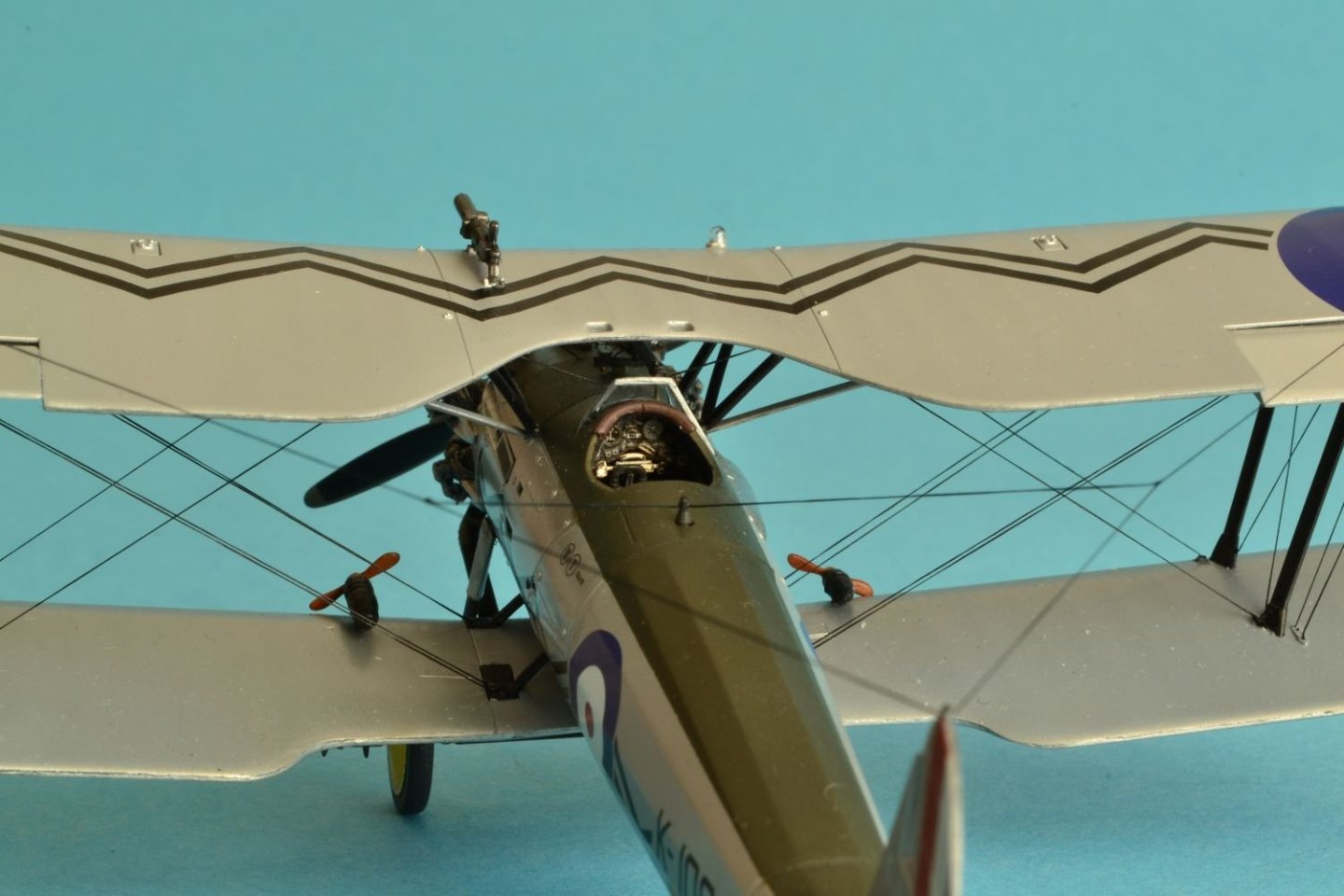
.thumb.jpg.c459ce4140b54c12eddb8eedfd446df3.jpg) Thank you Phil for your nice comment! Thank you Gary! Yes, the size of this model is quite minuscule although 1:48 scale. The biplanes of that era were not large in comparison with more modern stuff. Sometimes I struggled to get around the model especially when working between the assembled wings. Best regards, Dan
Thank you Phil for your nice comment! Thank you Gary! Yes, the size of this model is quite minuscule although 1:48 scale. The biplanes of that era were not large in comparison with more modern stuff. Sometimes I struggled to get around the model especially when working between the assembled wings. Best regards, Dan -
Danstream reacted to a post in a topic:
Lotus 72D by DocRob - FINISHED - Tamiya - 1/12 - Plastic/Metal - The Legend
-
 DocRob reacted to a post in a topic:
Lotus 72D by DocRob - FINISHED - Tamiya - 1/12 - Plastic/Metal - The Legend
DocRob reacted to a post in a topic:
Lotus 72D by DocRob - FINISHED - Tamiya - 1/12 - Plastic/Metal - The Legend
-
Canute reacted to a post in a topic:
Bristol Bulldog by Danstream - FINISHED - Airfix - 1/48 - PLASTIC
-
Canute reacted to a post in a topic:
Lotus 72D by DocRob - FINISHED - Tamiya - 1/12 - Plastic/Metal - The Legend
-
Danstream reacted to a post in a topic:
Starcraft Adjutant AI by yvesvidal - 1/6 - RESIN/PLASTIC
-
Great news, Rob. Finally your black beauty is successfully concluded. Great model with a great finish. Cheers, Dan
-
 Danstream reacted to a post in a topic:
Lotus 72D by DocRob - FINISHED - Tamiya - 1/12 - Plastic/Metal - The Legend
Danstream reacted to a post in a topic:
Lotus 72D by DocRob - FINISHED - Tamiya - 1/12 - Plastic/Metal - The Legend
-
Thank you Alan for your nice comments about my build. I am sorry for your misadventure at Schiphol. I live not far from there and I could have brought you to a huge hobby shop nearby Schiphol to spend some time (and money perhaps), although visiting Amsterdam is much more interesting from artistic and historical point of view. Good luck for the continuation of your trip, cheers, Dan
-
 Danstream reacted to a post in a topic:
Bristol Bulldog by Danstream - FINISHED - Airfix - 1/48 - PLASTIC
Danstream reacted to a post in a topic:
Bristol Bulldog by Danstream - FINISHED - Airfix - 1/48 - PLASTIC
-
Thank you a lot Andrew for your nice comments. I appreciate them! Thank you Ken, I am glad that you like my work. Yes, Airfix is very good. Wow Martyn, thanks for your great comment. Best regards, Dan
-
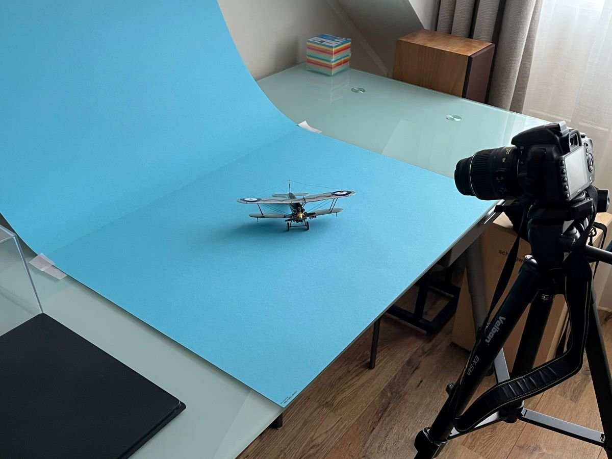
Than you Jan for your kind comment which I appreciate greatly. I am also happy that you commented positively the pictures. About the setup, I have to admit that my setup is very basic and simple as shown in the picture below. I just use what I had in the house. In the past, I was used to use two 5000K table lamps, but recently I like to use natural light diffused by the window light curtains. I hope that my basic approach is not disappointing anyone. I always tend to stay as basic as possible in many of my activities and step up with equipment only when necessary. Of course, the drawback of this simple setup is that you have to wait for a bit of sunshine and this is sometimes a bit of a difficulty in winter here in Holland 😉. What I do to get best results is to use a very small diaphragm aperture to get the maximum depth of field and use the maximum tele lens setting to flatten the perspective. Both of these things call for extremely long exposure times which require clearly the use of a tripod. For triggering, I use a timer, so I don't need to touch the camera to shoot a picture. In addition, I very often take several 'bracketed' under/over exposed shots and select the one that I like best. I hope you like my, perhaps, too long explanation, warmest greetings, Dan
-
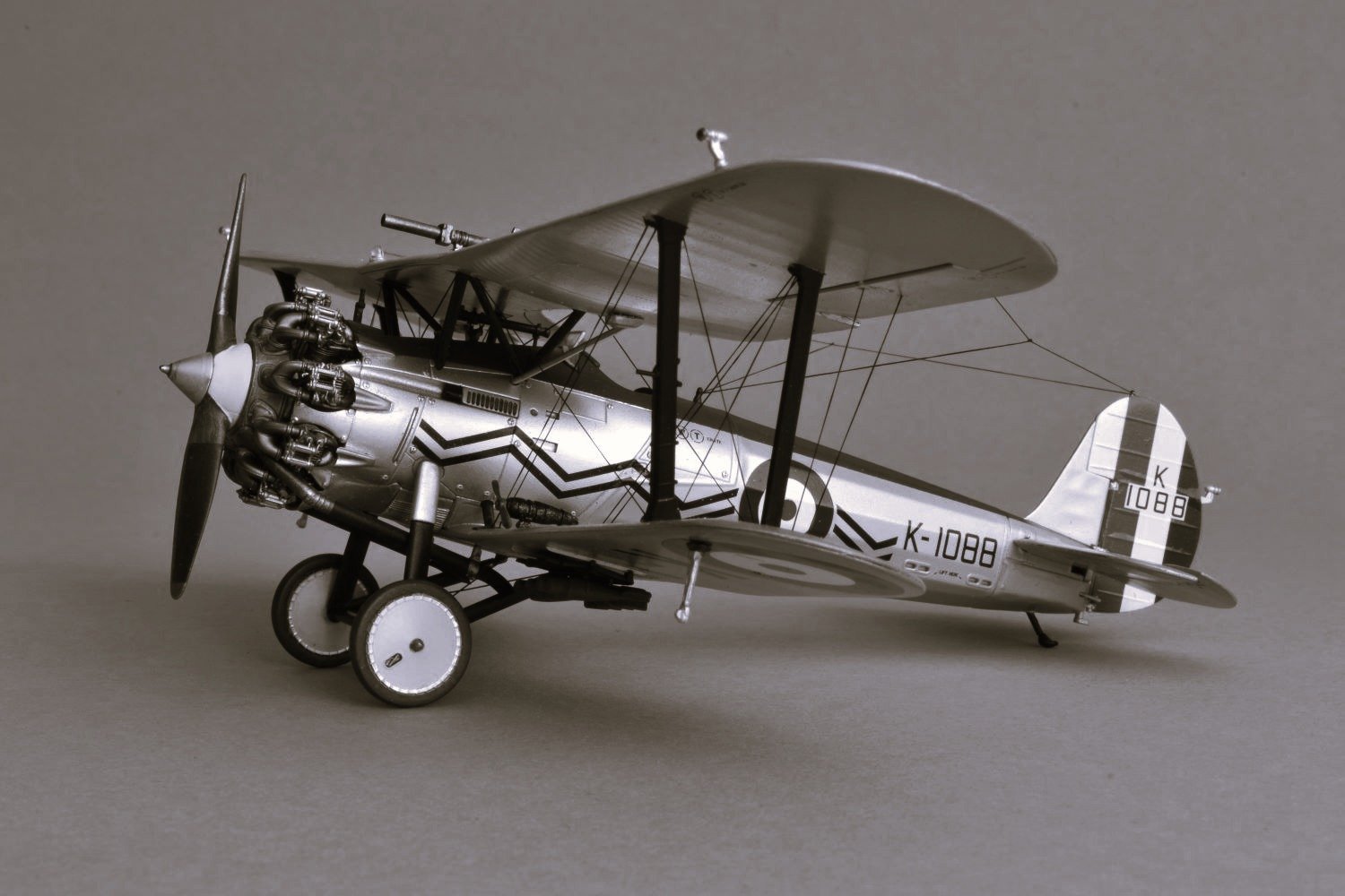
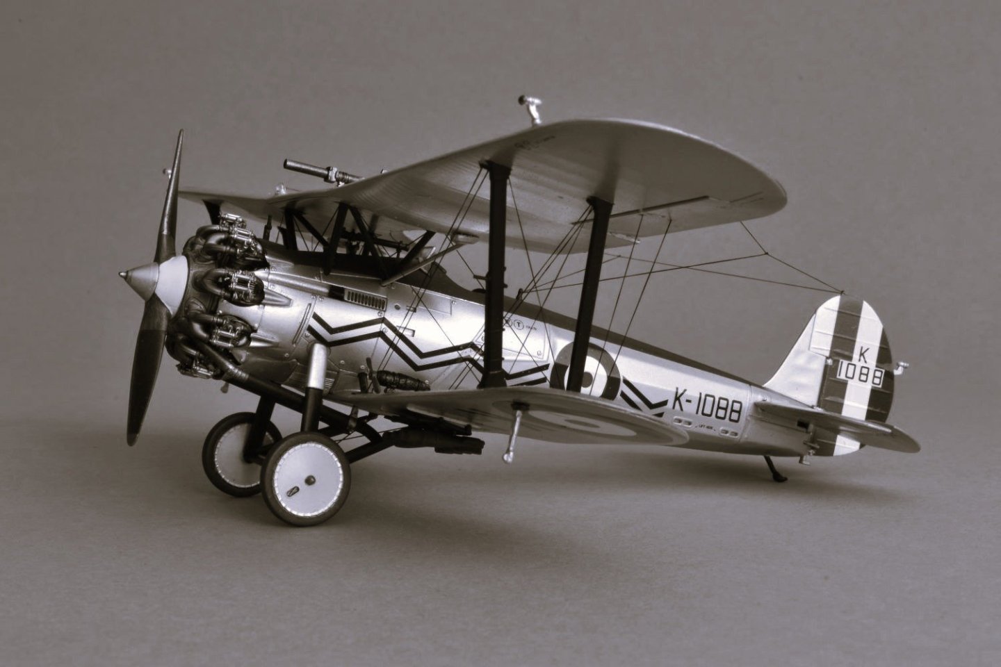
Thank you Chris! Thank you Rob for your positive comment. I also like the B&W shot version, I often play with that. Thank you Yves for your enthusiastic comments about my model! Yes, the latest Airfix kits are getting really nice. Best regards, Daniele
-
As others said, leave it alone for a while, then come back to it with a fresh mind. Cheers, Dan
-
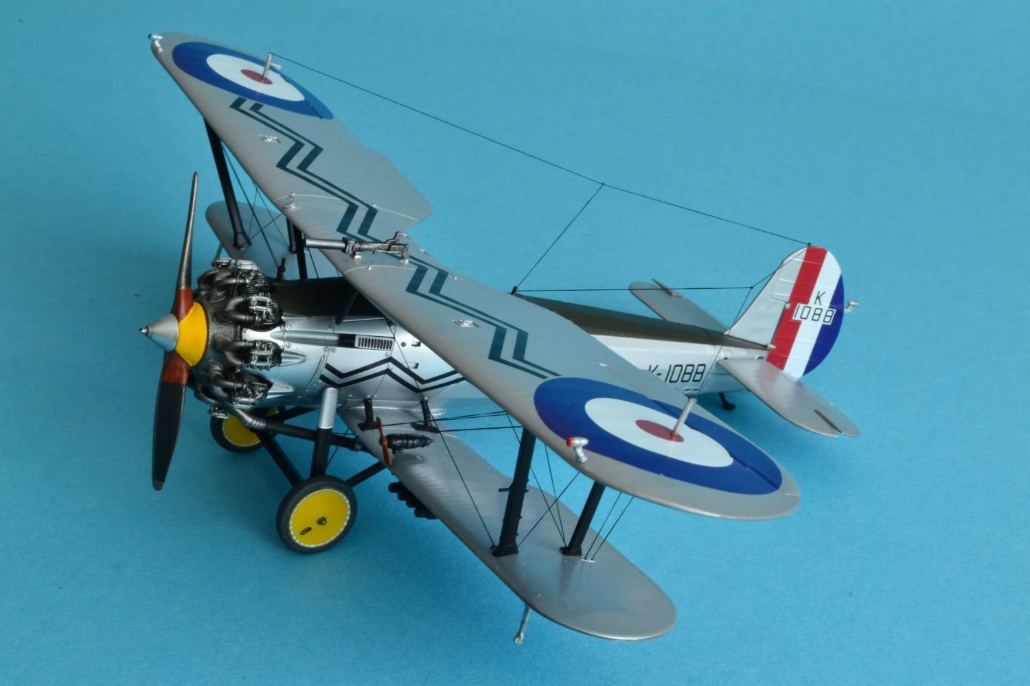
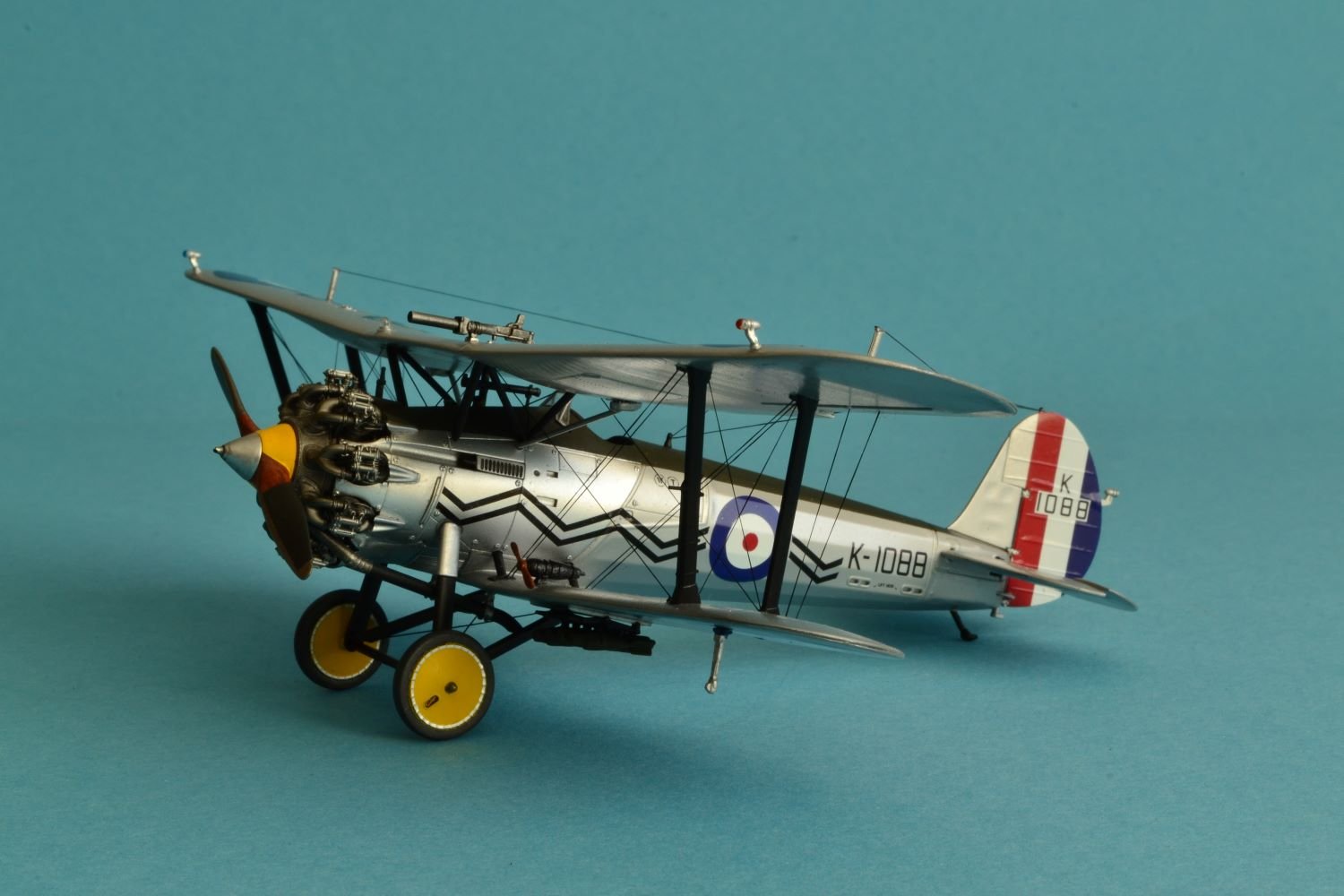
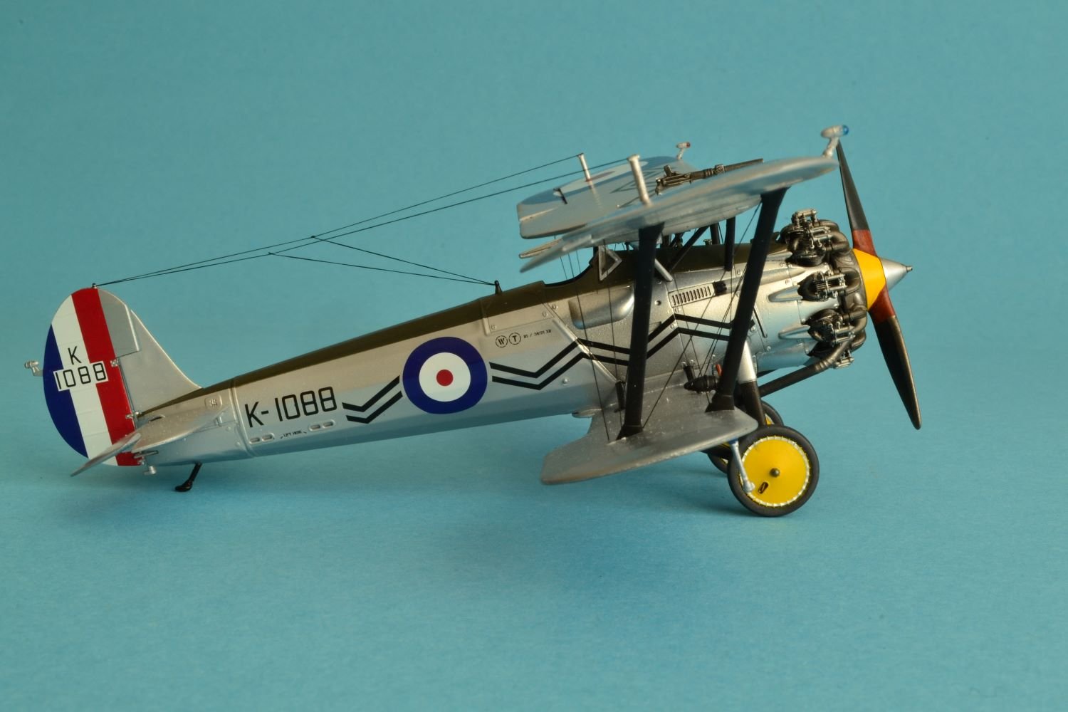
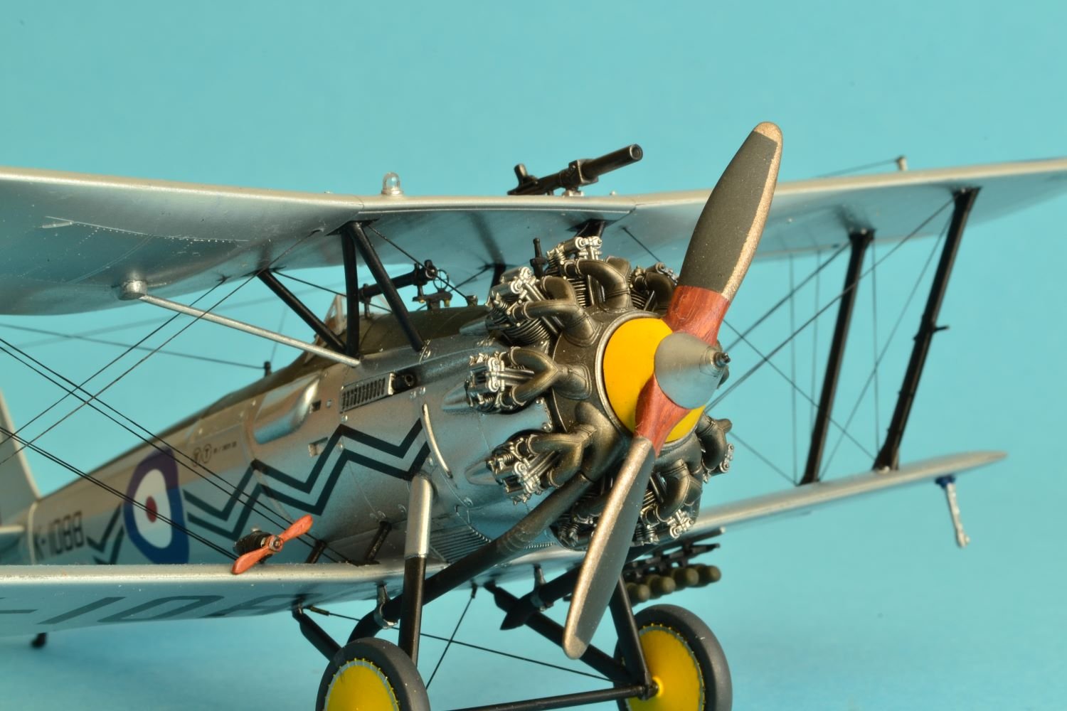
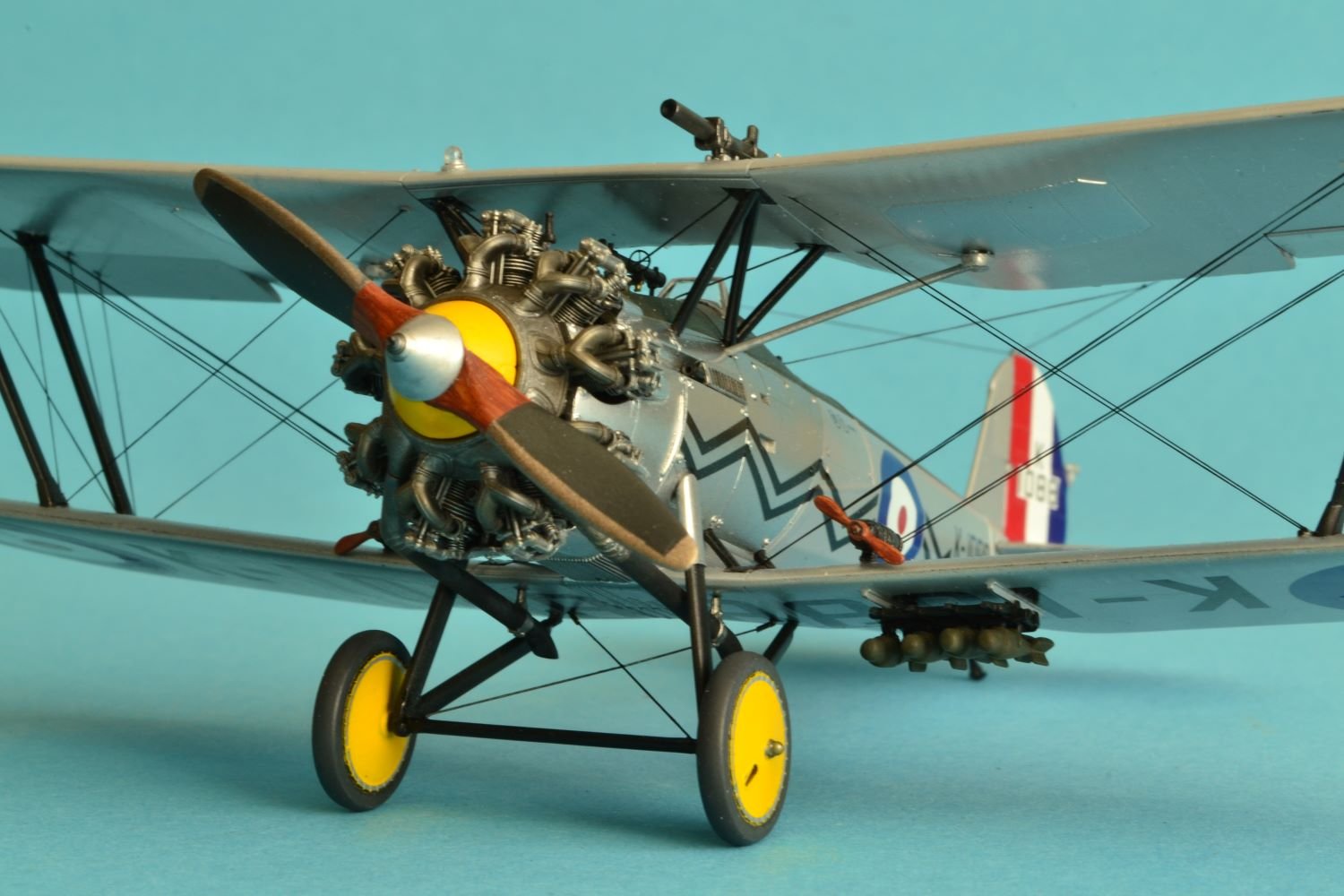
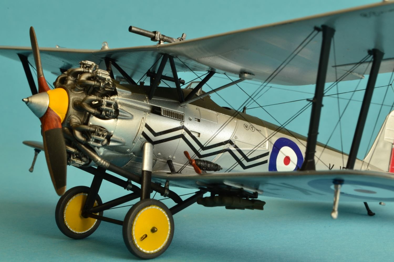
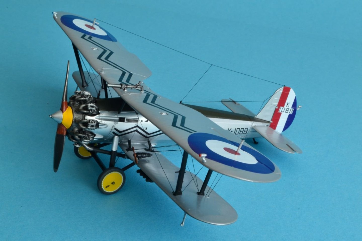
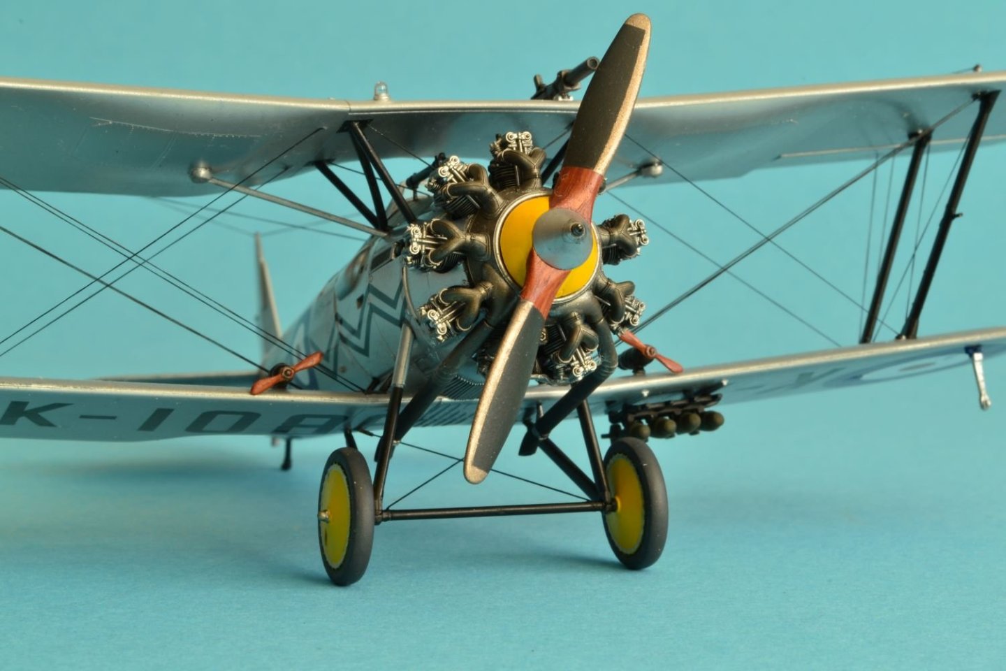
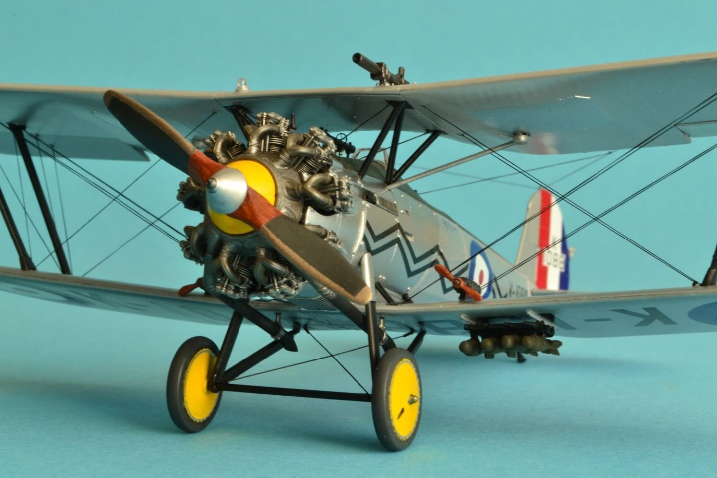
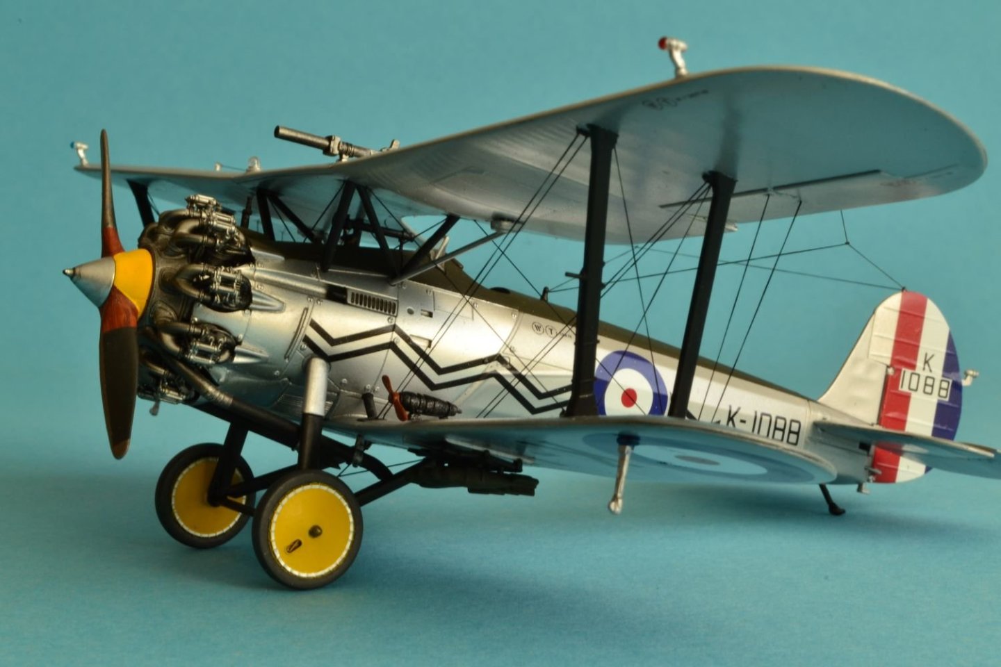
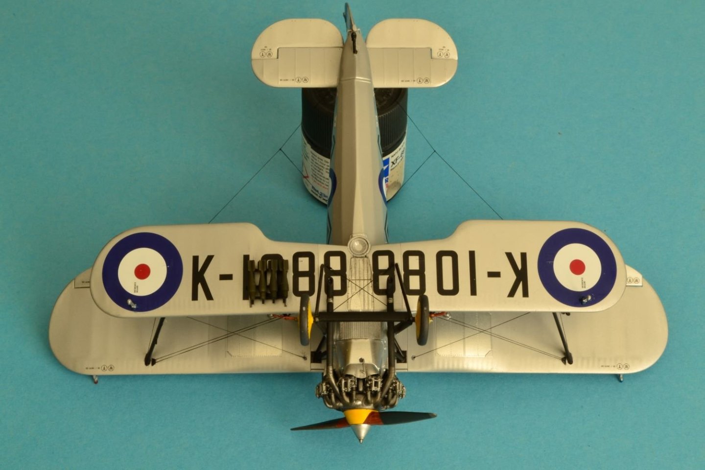
Dear all, after a long absence, I am back with the final pictures of my completed model. Bristol Bulldog MK II No.17 Squadron, Upavon, England 1930 This is the recent Airfix 1:48 scale kit which I competed by the end of last year. As said above, this kit is very nice, with a very good fit, especially for the inter wing struts which go together with no necessary adjustments. I liked building it, but I didn't like the quality of the plastic. Being a biplane, I think that the sequence of assembly is not for beginners and also the sequence for painting it is not the easiest. But I am pleased with the final result. The rigging was a bit of a challenge for me, but the instruction sheet provides an excellent guide for it. I took these picture with a Nikon D3100 with its aperture priority mode under natural day light. I hope you like also this model and any comment or criticism will be welcome. Best regards, Daniele


- 63 replies
-
- 14
-
-
-
I have just seen the last pictures of your finished Arado. It looks great, you built an impressive model very carefully detailed and finished. You implemented a rather high degree of weathering, but that looks quite credible. Well done, especially thinking that you are new to this genre. Best regards, Dan
-
Very nice build, painting job looks great. Best regards, Dan
-
Glad that you recovered so well the number decals. As you said, the finish looks like a piano, simply beautiful. Cheers, Dan
-
Thank you Gary, for your nice comment. Indeed, it was a bit of a work to paint all the various finishes, but it paid off. Regards, Dan
-
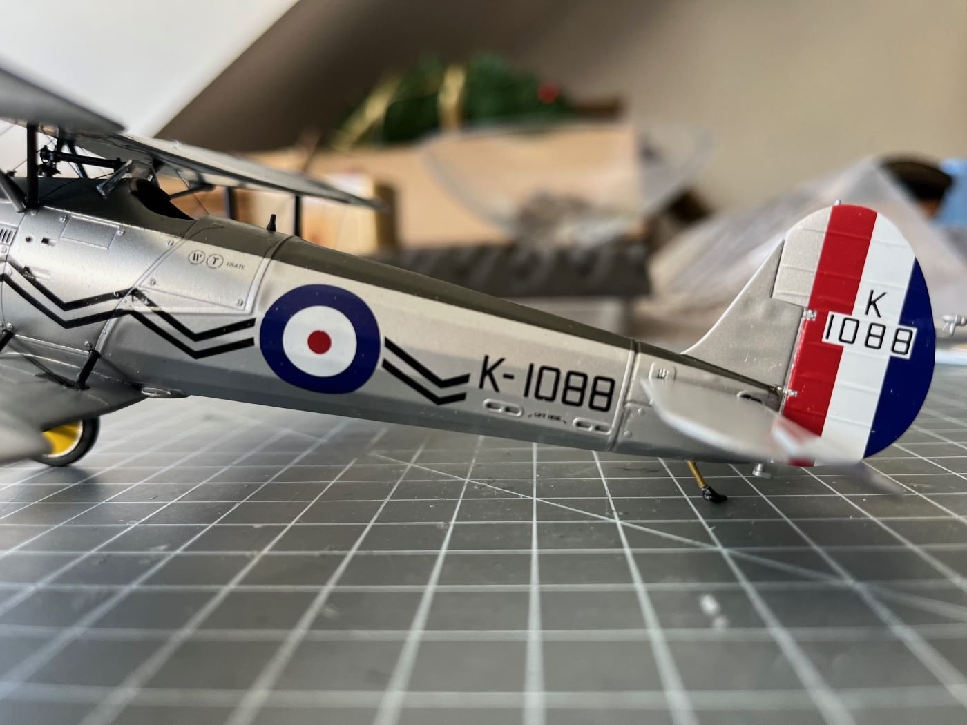
A very short post with only one picture just to show the repaired tail skid (as I said, I replaced the bent part with a piece of brass tube): To answer to Andy, @realworkingsailor, this picture shows also one of the fin flash decals that are now glued on. Due a trip abroad, I will have this build on hold for a while. Enjoy your hobbies and see you in a couple of weeks, Dan
-
In fact, this is why I need to repair it asap before I finish the build. Cheers, Dan
-
Thanks Andy! Indeed, it is very easy to damage the finish and the more you go on with the build, the more difficult is to repair it. It was an interesting building experience. For the fin flash there are two options, one is a complete three colors decal for the complete rudder, the second is to leave to the modeler to paint the three bands and then just add the identification letters and numbers. At this point, I am a bit tired of this model, so I am going for the quicker former one. Cheers, Dan