


BANYAN
-
Posts
5,537 -
Joined
-
Last visited
Content Type
Profiles
Forums
Gallery
Events
Posts posted by BANYAN
-
-
Ports and Hull Fixtures
The airing and loading ports were cut into the hull planks with a sharp chisel and the hinges applied. The port hinges are photo etched shim brass which have been blackened and glued with CA. These were drawn up in Corel Draw and etched by a contact in the Railway modelling world. I was quite pleased with most the etched pieces and will definitely use this process in future builds; maybe even try etching myself.
I decided to apply the hinges to the airing ports opposite to that normally fitted to most models. I have based this decision on intuition, but I should check this against contemporary models and references for accuracy. My thoughts were that these would have been used mainly in port where when the ship was laying into the wind, the wind would be funnelled into the port. This principle also works if the ports were opened in calm seas in the tropics where the ship's motion would funnel the wind into the ship as the port lid would open aft.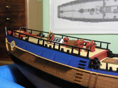
The gangway steps were made from a single length of walnut which was shaped by scraping with a profile cutter made from a hacksaw blade with a mould shape cut into it. Individual steps were then cut off to length and glued into place. The following photo shows the gangway steps, boat skids and the starboard sheets fairlead (with brass sheaves).
- NMBROOK, PeteB, avsjerome2003 and 1 other
-
 4
4
-
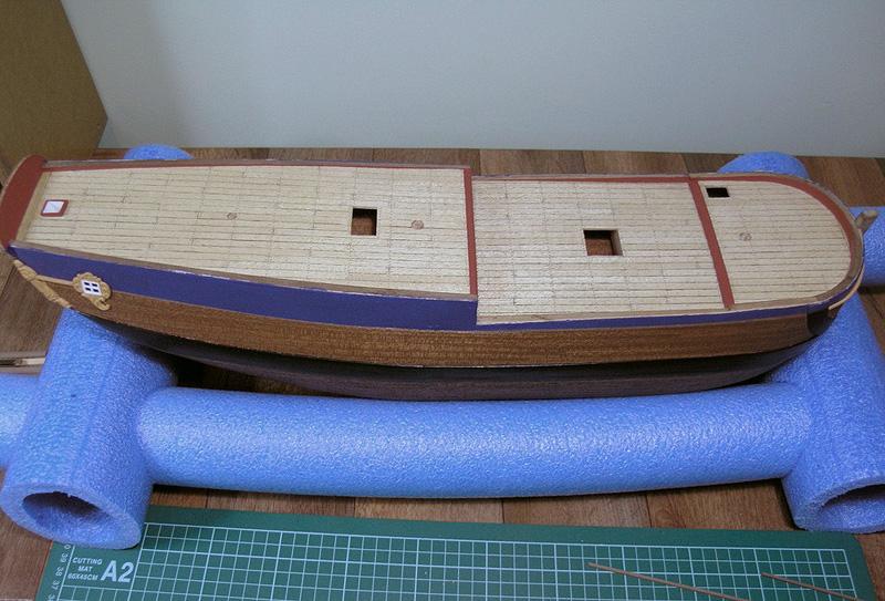
Deck Planking
I have tried to remain true to scale with the planking. The size of planks in ships was determined by the availability of timber stock at the time, so I opted for something in the mid-range for a typical plank length in this era. The plank size I used was based on boards of 12 inches width by 25 feet long (actual), which at 1:60, equates to 5mm wide by 125mm long. This proved very convenient as the kit supplied deck 'Mukall' planking plank strips, were 0.5 x 5mm wide.
For the deck planking, I again opted for a 4 plank butt shift, centred from a slightly wider king plank. This was a relatively straight forward activity, and with her bluff bow, there was no need to worry about nibbing and joggling into a margin plank. I was not sure whether to use a waterway or not, but in the end decided not to, as at this scale it would have been a little too awkward (for my skills at that stage and as a first build). I now regret that decision, but I have learned a valuable lesson. I have not ruled out the option of a retro-fit just yet.
The mast holes were drilled at this stage. I had placed filler blocks of poplar pine between the bulkheads in these areas to provide additional support for the masts. These were pre-drilled and then redrilled under a very large mill working with ever increasing drill bit sizes until achieving the correct diameter. I used a protractor to determine the correct rake from the kit plans, and reconfirmed with Marquardt (based on dockyard drawing/plans). Dummy masts (dowels) and a digital angle level were used to ensure the masts were correctly raked and aligned (fore-to-aft) on the model.
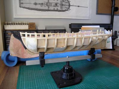
The model is shown in her working cradle which is made from pool spaghetti (available at Clarke Rubber for the Aussies). This has proved a very versatile building cradle since completing the first layer of planking. I used the Amati keel holder during the assembly of the skeleton and first layer of planking.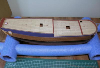
-
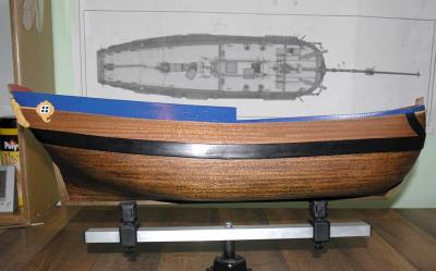
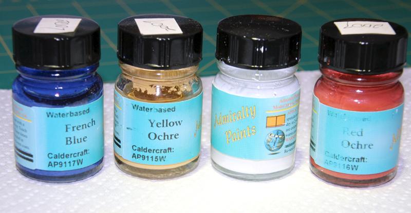
Paint Scheme
At this stage, I had to make the decision to paint or use natural timber. After much dithering, I decided to paint. I have used the JoTika/Caldercraft Admiralty series of paint which is claimed to be based on the same pigment colours used in the original paint found on Victory which also hails from the same era. I am happy with my decision to paint as, for me, it seems to provide a little ‘life’ to the model.
One lesson learned with paint (especially if taking some time to build) is that there will be the inevitable wear and tear on some of the
fittings as different jobs are done after fitting a painted piece. A close look at the heads on the carricks in some of the earlier photographs will show what I mean. I am glad I found these now as touching up after doing the rigging may have been difficult in places.
-
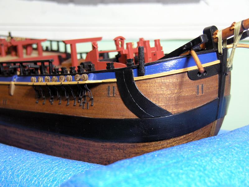
Wales and Anchor Lining
The wales were glued to the first layer of hull planking before applying the second layer. I used continuous run planks of the appropriate thickness which I butt jointed. I do not think that the owners/builders of a collier would have expended money on the Admiralty preferred anchor stock joinery. As the wales were to be painted, I did was not overly concerned with the joinery; a good sand and coat
of paint hid most of my poor quality joints .
.The anchor lining and bolster were applied over the second layer planking and sanded down to be flush with the thickness of the
wales. The side view of plans and drawings provided with the kit are very misleading as this feature is, by the nature of a 2D drawing, shown flattened or fore-shortened as this feature is located at the start of the curvature of the hull. As such, the drawings do not truly reflect the actual curve imposed to these strakes.
To achieve the positioning and sweep of these planks, I temporarily fitted the anchor where it would ride when hoisted in and lashed to the fish davit; I then let the anchor swing through its path watching the end of the flukes as it swung after it would have been released from the davit to hang from the cathead.

- NMBROOK, avsjerome2003, PeteB and 1 other
-
4
-
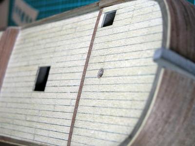
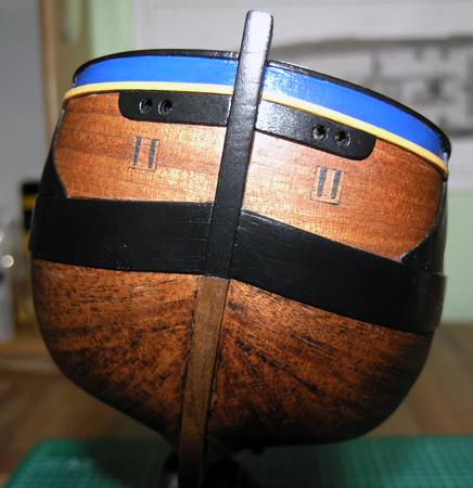
Hull Planking
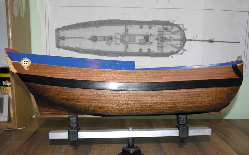
The planking timber supplied in the kit (limewood) was used for the first layer, and Sapele (Entandrophragma Cylindricum) which is in the Mahogany family/genus, was used for the veneer second layer (5mm wide strips). I decided to use a 4-butt shift planking pattern which have been aligned to fall on the closest frame (estimated only).
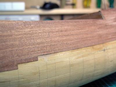
The darker colour showing below the wale is the fortunate result of a failed experiment in which I had attempted to simulate the tar based 'brown stuff' used on Endeavour as a protective layer against 'worm'. I tried a bitumen based coating applied to car bottoms (anti-rust) which resulted in a great and authentic looking bottom. However, with time and a little hot weather, it soon became apparent this was a major error as the bitumen based coating started to melt. After scraping it back and re-sanding it, the bitumen that had soaked into the wood and crevices gave it a very nice look.
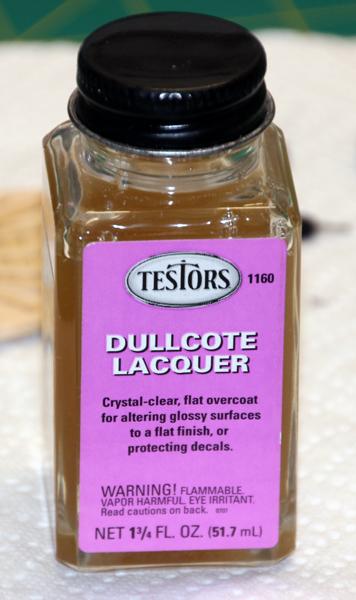
After some sanding and a coat of Testor's DullCote, it came up quite nicely. I decided not to simulate the trennels in the side planking as it made the model look a bit busy, and most would have been covered by paint anyway.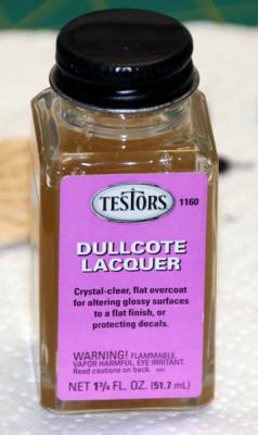
- NMBROOK, PeteB and avsjerome2003
-
3
-
Constructing the Hull
Unfortunately I did not keep any of my photographs taken during the construction of the skeleton of the hull; the hull is shown here with both planking layers completed.
The backbone and bulkheads were plywood but I found them to a good fit with no warping which was a real bonus. I filled the space between forward bulkheads with balsa fillers which I then shaped as part of the fairing process. A valuable lesson learned here was to seal the balsa with a diluted PVA solution as the glue I applied to the planks was being rapidly absorbed and not bonding to the planks.
I also fitted pine blocks to either side of the backbone at the points where the masts would be fitted to provide greater strength when I drilled the mast holes later.
- avsjerome2003, NMBROOK and Whizgig
-
3
-
Other Builds
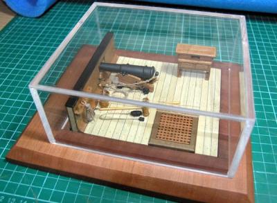
While completing this build, I have also been diverted with some other interesting builds along the way. Amongst these are having made a start on Chuck’s Syren and his Longboat. I have also completed a Battle Station (based on Russ’ plans) - see here
- AKRYPTO, avsjerome2003 and PeteB
-
3
-
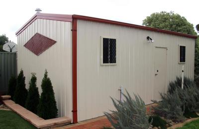
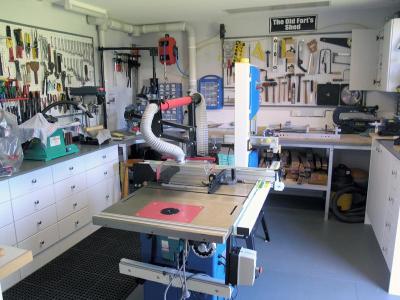
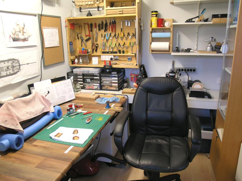
The Builder's Yard (Workshop)
I originally started building this model in a spare room in the house. I have since built a workshop (aand many more "honey please do! small jobs) which have contributed to the extended model build time. However, finally, I can concentrate on the build!

- robin b, olliechristo, PeteB and 2 others
-
5
-
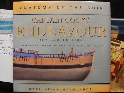
I am building Endeavour to represent her in her most likely configuration in 1768 (i.e. the converted collier, Earl of Pembroke, fresh out of the dockyard at the start of her epic journey). I have been using the AOTS “Captain Cook’s Endeavour” (revised edition) by Karl Marquardt as my primary reference, supplemented with Ray Parkin’s 2 volume “H.M. Bark Endeavour: Her Place in Australian History”, and over 100 photos I took while visiting the replica ship.
I have also purchased a copy of Endeavour's Ship's Log from the NMM in the hope of extracting just that extra bit of information. It is interesting to read this Log kept in Cook’s own hand and achieve some sense/feeling of being there while reading it.
(Used with kind permission of author)
-
Build Background
I won’t provide a historical background for the Endeavour as it is an extremely well known ship and modelled extensively. My decision to build Endeavour was based on my desire to model ships that were involved with the charting and exploration of the Australian coastline; or, had a major influence on Australian History. All going well, I hope to include the following ships in my bucket list:- HMS Investigator of Mathew Flinders fame (research well underway);
- HMS Mermaid (Cutter) and Tom Thumb of Bass and Flinders Fame.
- Additionally, I am also researching the HMCSS Victoria, which was part of the Victorian Colonial Navy, and a unique ship due to its era and construction.
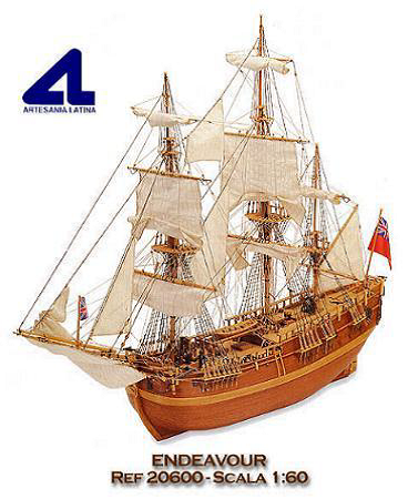
I started building Endeavour in late 2006 and as you can see in the following photos, I have managed some progress, but nowhere near the speed at which I would have liked. The build is based on the Artesania Latina (AL) kit; however, I have only used the backbone, bulkheads, planking strips and some of the kit's accessories/materials, the rest of the kit materials went into the bin J. I selected the AL kit as the base for my model as the scale is good for display and I was reliably advised that the kit’s hull dimensions were reasonably accurate.

(AL graphic from the kit box) -
Hi All,
I have been reluctant to create a build-log as with my paying job taking up a lot of my time, the updates have been, and will continue
to be irregular at times, readers might think the build dead. However, I have been convinced to create a log so here goes.
I have been slowly building (over the past seven years) my heavily bashed HM Bark Endeavour at scale 1:60 - Model length 31-2/2"/ height 25".This is my first major build and I am still learning as I go. I found I rapidly became disappointed with the quality of the materials and the poor instructions of the kit and decided to considerably modify it. Along the way I have also experimented and learned many valuable lessons for future builds. I have also managed to build a rope serving device and establish my tools and wood supplies for
future builds (including my 'man cave').Index
Cathead, Fish Davit and Boomkins
-
Topic Reconstruction
Folks, the earlier posts are a rebuild of my original log in MSW 1.0. It does not contain any of the background chat or questions asked, so if you recall any questions that may continue to be useful please ask away again.
Many thanks.
Pat
-
Geez, you do like to set me a challenge Greg and just when I thought I might beat you in catching up with the build-log
The masts look great. I am about to add all the additional furniture and fittings to mine. What did you use as your main reference as to what cleats etc went where?
cheers
Pat
-
Great to see you repost all of the log Jason, she's coming along nicely. You'll be onto yopr next build before you know it
cheers
Pat
-
Glad you reposted this build Russ, it is a great little first-up scratch builders project as you say. One positive or advantage of the site rebuild is the opportunity to revisit all these great builds as they are reposted.
cheers
Pat
-
Great to see the log back Chuck. This is a very fine example of 'boat' building based on a very intyeresting design and an example of very precise joinery.
cheers
Pat
- thibaultron and Chuck
-
2
-
Hi Robbyn,
It is also worth considering the overlap/alignment of the first and second layers. If it is possible, it is preferable to overlap the first and second layer longitudinal joints (that is, not have them coincident). This provides additional strength and assists in stopping the hull joints opening if for any rreason they become wet (just ask a couple of members hows their models were accidently saturated by water leaks and the like) or in humid.hot climates.
cheers
Pat
-
Glad to see you repost this great build mate.
A quick question. How do you fit the round hole of the cap to the topmast (place the topmast into this hole)? I am building the caps for my Endeavour and find that with the 6 sided beveled conical piece at the top I simply cannot slide it through and I have had to cut the calp[s in two longitudinally.
cheers
Pat
-
Hi Mark,
I have also used one for some time, and as you say, very useful within its limitations - Even with a mitre box I find it difficult to get nice straight cuts for planks. This link takes you to an article in the MSD which shows some interesting modifcations.
cheers
Pat
-
You're ahead of me Greg, I am still rebuilding mine in a word file to allow quicker rebuild. I had forgotten your "porcupine" hull
cheers
Pat
-
Hi Slog,
Mate, looking good and don't worry - I have been on mine since 2006


cheers
Pat


HMB Endeavour by BANYAN - FINISHED - Artesania Latina - 1:60 - circa 1768
in - Kit build logs for subjects built from 1751 - 1800
Posted · Edited by BANYAN
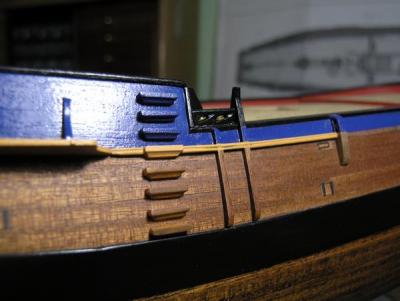
Chains and Channels
The channels proved to be a very challenging job for me until I realised that by using brass pins on the inner edge I could get a stronger
and tighter fit with the hull. I had to do the job twice, as at first I had fitted them perpendicular to the hull side rather than parallel to the water. The channels have an outer hardwood (walnut) edge which was glued to the inner channel plate after rebating the deadeye chain recesses.
The chain plates have turned out reasonably well, but are a little ordinary in some places. The walnut deadeyes were the ones provided with the kit; however, I used different chain plates to those provided, and these had to be modified to suit (a lot of silver soldering).