
Supplies of the Ship Modeler's Handbook are running out. Get your copy NOW before they are gone! Click on photo to order.
×


BANYAN
-
Posts
5,867 -
Joined
-
Last visited
Reputation Activity
-

 BANYAN reacted to Jeronimo in LE BONHOMME RICHARD by Jeronimo - FINISHED
Hello friends,
new pictures of the Bonhomme Richard.
Karl
T e i l 38
C Gun-Deck
Timbers and planking
-
BANYAN reacted to Piet in Hr. Ms. O 19 1938 by Piet - FINISHED - scale 1:50 - submarine of the Royal Navy Netherlands in service 1939 - 1945
Today I started with the bow torpedo loading tube. I cut a hole in the forward deck for the hinged hatches and ground a space out for the brass tube and added some more wood behind it for better support. I also pre-cut the holes for the escape and entry tubes in the fore deck.
Then I proceeded to the aft deck and cut the rectangular hole for the stern torpedo loading tube but have not made any further provisions to secure the tube. The stern escape / entry tube is located and marked on the deck but have not cut the hole for it, yet. The edges are just inside the side deck plates and that concerns me a little, however, according to the drawings and photos that's about right.
As noted on one of my previous posts, I have to rework the deck area above the side launch torpedoes. This brings a lot more work but it's according to the deck layout drawing and I should have paid more attention to it before doing it my way (sorry Frank Sinatra ) Oh, I really don't mind it though, I learned a few things in the meantime. With all those hinged hatches between the "tracks" I'll most likely only make the ones above the side launch torpedo launcher. The rest will be indicated as I'll do with some other hatches on the deck.
Okay, that's about it for today and I took a few shots of what was done.
This is a shot from the future conning tower of the forward deck area. I have annotated the particular items of interest. I have just stuck a piece of 10 mm brass tube in it's semi prepped location and it still needs to be cut to the right size. Then it needs the hinges soldered to it and a lid must be made also with hinges. I also need to add small planks of wood for the hatch hinges. There are two pairs and these will fold outboard.
This is another view of the forward deck with annotations. I have just laid the "rails" loosely on the deck to where they are to go.
This is where we are today on the rear deck. I have to make a block to support the brass loading tube which will then be glued to the top of the pressure hull. Here too, I'll have to glue in a few strips of wood under the deck for the hatch hinges.
I just drew the outline of the future side mounted anchor. I'll make that one when I receive the soft copper Paul so graciously is sending to me. This'll be a fun little model.
Couldn't resist making a close-up of the stern area to show how nice it turned out. In looking at the pic I see that I still need to clean up a few things, still a few "fuzzies."
Cheers,
-
 BANYAN got a reaction from trippwj in Harriet Lane by trippwj - Model Shipways - 1:144 Scale
Good to see you back at the build again Wayne - now, I just need to motivate myself also
cheers
Pat
-
BANYAN reacted to Dan Vadas in HMS Vulture 1776 by Dan Vadas - FINISHED - 1:48 scale - 16-gun Swan-class sloop from TFFM plans
Thanks for the kind words Sherry, John, John and Popeye .
I've marked and drilled the holes for the treenails on both decks. As most of the planks (apart from the Kingplank) are no wider than 8" they only get one treenail.
Danny
-
BANYAN reacted to Jim Lad in Francis Pritt by Jim Lad - FINISHED - Scale 1:48 - Australian Mission Ship
Well, a little sawdust has actually been produced. The 'backbone' of the 'Pritt' is about halfway there. It looks a bit odd at the moment with only the after end done and no stem, but I forgot to take my stock of wider timber to the museum with me so I had nothing to use to cut the curved pieces for the forward end - next time.
Here's the keel, sternpost and skeg/after deadwood, anyway.
John
-
BANYAN reacted to Piet in Hr. Ms. O 19 1938 by Piet - FINISHED - scale 1:50 - submarine of the Royal Navy Netherlands in service 1939 - 1945
Hello everyone, again.
Well, today was going to be THE day of painting the sub with an enamel primer. I used this primer before and it dries nice and hard.
I took it outside next to the garage and put it on one of the Admiral's large plastic garden barrels as my paint station.
Then I used my shop vac to blow all the dust off it after the sanding I gave it in the last couple of days. Then wiped her down with a damp rag with solvent. I used a primer in a "rattle" can from the local hardware store, like Krylon but dries harder. I put two coats on it and let it sit in the warm sun for a few hours.
In the meantime I put the mushroom anchor back in the lathe and cut it down thinner and hollowed it out to make it into a dish shape. Then cemented the anchor post into it with 5 minute epoxy and also put an eye bolt inside the hull to hold the anchor "cable", which is just a piece of heavy black rigging line.
I drilled a hole in the center false vertical keel for the anchor post and made and installed the eye bolt into one of the frames. Then fastened the anchor cable to the eye bolt and the anchor and stuffed the cable inside the hull. The anchor fits nice a snug in it's little "house" and all we see is the rounded bottom of it, quite neat to look at. The Admiral asked where the anchor was so I told her to bend down and look under the bow, ooooh, she said, I see it's bold head. Weird Dutch humor
She really liked the looks of the boot now that it's painted white.
I mentioned in a previous post that with the primer on it I should be able to see all the blemishes and sanded through spots, etc.
Well now, this afternoon I took the boot outside and sat in my lawn chair in the shade with some 400 sandpaper and scrutinized the hull for any of that funny stuff and was pleasantly surprised how few little thingies I found that needed some attention. I did sand it down very lightly to remove some of the grittiness from the paint and it's looking really good, I am a happy camper
So, I guess we can now put some color on it. I have a gallon of semi-gloss enamel called "Roasted Pepper" that we used for our front door. I love the color because it's not a fiery red but more a subdued red. It's the same paint I used for the VOC ship gunport lids. It'll be red up to the waterline and above it a forest like green, which I have not picked out yet.
Well, here are two shots of the boat just painted with primer.
Cheers.
-
BANYAN reacted to Dan Vadas in HMS Vulture 1776 by Dan Vadas - FINISHED - 1:48 scale - 16-gun Swan-class sloop from TFFM plans
Thanks for that link to the LoS Grant, I'll get some from them.
Forecastle and Quarterdeck Planking
The Forecastle and Quarterdeck have been planked. Both decks have tapered planks as well as a couple of Dropped planks each. Here are some progress pics :
At this stage none of the planks have been sanded - these pics were taken just after the last two were glued in. The "caulking" smudges will all sand out evenly. There are one or two very small gaps which will be filled with a sawdust/glue mixture.
Treenailing is next.
Danny
-
 BANYAN got a reaction from sonicmcdude in Scary ruler discovery
Sinan, but first check the caliper is accurate first Mine were out and I have just invested in a "Certifed" digital readout Caliper.
Per, the other trick is to check them for straightness. I believe the check is done by using one edge to draw a line then flip the ule vertically (same edge but running the other way) and draw another line over that and see if they are coincident - repeat for the other edge. I use a square or solid base to rest the ruler on but you need to be sure the bases (short edges) of the ruler are square also. There used to be a good write-up on MSW 1 ... another lost ....
cheers
Pat
-
BANYAN reacted to RGL in HMB Endeavour by RGL -FINISHED - Artesania Latina
Slowly fitting the topmasts. I just have to glue in the mast tops and align it properly before setting it for good.
I had to include the tackle first as the shrouds will run over the top of them so they fall in a single line thus it has to be spliced. The double blocks are Chucks from Syren, drilled out a bit and filed along the sheeve lines to give a little more definition.
shrouds next, then numerous backstays, then stays over the top, Then I'll have to worm the jeers up between them so they hang under it all.
-
BANYAN reacted to Piet in Hr. Ms. O 19 1938 by Piet - FINISHED - scale 1:50 - submarine of the Royal Navy Netherlands in service 1939 - 1945
Hello all y'all,
Today was a little frustrating with a minor setback I tried the cemented dive planes but the port side is not secure on the inboard hinge pin. Soooooooh - - - I'll have to redo that one again. I even put some anti seize compound on the pin going through the keel and on the ends of the bushings to prevent the epoxy cement from sticking to it.
I'll give it one more try and if that fails then I'll have to go to plan B, which is using the 1.5 mm pipe as a hinge pin.
I made the net/cable cutters for the leading edges of the dive plane outboard brackets. I purposely left these un-cemented so I can still remove the dive planes. They will only be cemented in place when I am positively sure the center hinge pins are secured in the dive planes.
I filled the rudder slot with wood filler and finished it off nicely. Did not use paper to cover it.
I also cemented both engine exhaust pipes into the fairings.
Well, I made a few pics of the problem causing dive planes anyhow and the other things mentioned above.
This shows the net cutter cemented to the leading edge of the outboard dive plane hinge bracket. It's still not cemented in place yet. I used 5 minute epoxy cement, the same as I used for the inboard hinge pin.
Another view of the net cutters installed and the dive planes.
I painted the exhaust pipes with flat black as well as the well they come out of.
An overall view of what was accomplished today.
Cheers,
-
BANYAN reacted to Piet in Hr. Ms. O 19 1938 by Piet - FINISHED - scale 1:50 - submarine of the Royal Navy Netherlands in service 1939 - 1945
Hello everyone,
Today was a good day,made good progress. I first fiddled with the small deck pieces and rails over the torpedo launch are to try and make them lay nice without a wiggle and even with the rest of the deck. After some scraping here and there and twisting they seemed to fit quite nice. I then cemented the wood decking to the rails . I used a slow curing epoxy cement so I could position the 1 mm deck pieces to the rails in situ and then remove them from the boat to clamp the wood to the rails. The cure time was 3 hours which gave me the chance to paint the launcher area with gray enamel. It's looking really nice but is still in need of some touchup.
Tomorrow we'll check the deck pieces for fit, again. One never knows what the paint will do.
I also finished installing the dock bumpers and put the poly urethane to the deck structure sides and the top side of the ballast tanks. I put two coats on but it needs at least one more coat to seal the paper really good. It got rid of some of the "fuzzies" from sanding and scraping the paper.
I also started with the dive planes and rudder. I am making them from a three layer sandwich of 1 mm plywood. That way I shouldn't be afraid of warping. They are cut out and being glued and clamped till tomorrow. Then they'll be finalized and checked for fit. Then they need to be shaped a little like an airfoil. Installing them with the hinge pins will be a challenge.
I don't know how much time I'll have tomorrow and how I'll feel after a two hour dental visit for a double tooth implant. Cut the gum, drill two holes in the upper jaw and screw the titanium studs in. Sow it all up and presto, done I am actually looking forward to it, these two will be the last ones and then I'm done with the restoration.
Okay, we are now ready to look at a few pics of the progress of today. Sorry no pics of all the small pieces for the rudder and dive planes, forgot
After a lot of fiddling, scraping and twisting these pieces I got them to lay down very nicely. It may just work to have them removable But I'll wait till the paint has dried and see what it did, if any, to change the nice fit.
Another shot of the deck area, still unpainted.
This shows the dock bumper strip, sorry for the out of focus pic.
Here we see the painted launcher area. Yes, there are a few spots that need touchup.
Another shot of the launcher area with the port door open.
Cheers,
-
BANYAN reacted to Jim Lad in Stag by Jim Lad - FINISHED - Scale 1:96 - English Revenue Cutter of 1827
Well, she's finished at last!
The last couple of details were finished at the museum yesterday. As you can see from the photographs, she still needs a proper stand and case - plus a bit of a clean off of odd dust particles before she's permanently cased - but she is complete at last.
I must say I'm quite pleased with the way she's turned out. I think I've got the spars fine enough to look realistic and make her look light and fast rather than just over sparred, but that's just my opinion.
The next model is currently in the planning stage and a new building log will appear shortly.
John
-
BANYAN reacted to Piet in Hr. Ms. O 19 1938 by Piet - FINISHED - scale 1:50 - submarine of the Royal Navy Netherlands in service 1939 - 1945
This morning I could spend some quality time in the shipyard. I made and fitted the two side deck pieces and the center piece from which I'll make the hatches. The 1 mm plywood is flexible and won't retain their flat shape. If I want to make this whole assembly removable then I'll have to add some small wood strips on the bottom. It's also possible that when they are cemented to the brass rails they may be stiff enough but who knows. That's the first place to start cementing the side deck pieces to the brass rails anyhow. There are a few other possibilities to secure the assembly in the center but we'll cross that bridge when I get to it.
Right now my interest is in how the hinged side doors work. I made the hinges and cemented them to the doors and the bottom of the deck sides. Have not tried it yet - - - - - keep our fingers crossed.
I also glued and screwed the exhaust shields to the deck structure. Looks quite nice, only had to add a little wood filler in a 1 mm gap in the starboard one at the rear, only about 10 mm long. The port side glued up real nice. I also cut the two exhaust pipes from aluminum tubing.
As the glue was curing on various parts I fitted the port side docking bumper. It is now also ready to be glued and nailed to the hull. More progress!
Okay, here are a few pics of what was done today.
All deck panels are now made and fitted. The center one will be cut up for the hatches. I think that the seems will disappear from view when the deck strips are installed. In reality they don't look as pronounced as on the photos. Everything is still loose.
This is a sideway view of the deck rework.
This shows the paper hinges I cemented to the inside of the doors and to the deck frame pieces. I put masking tape on the outside to keep the doors as tightly closed as possible.
The glued and screwed exhaust shrouds, looking aft. You can still see some of the evidence of wood filler at the aft end. This will also disappear with the final deck paint and decking strips. The top of the shrouds add some deck space to the aft hull. It is really needed there because the deck narrows and the stern torpedo loading hatch is in that area and the loading gantry. The crew needs some maneuvering space.
Exhaust shrouds looking forward.
Another shot of the exhaust shrouds looking forward on centerline with the pipes.
This is the docking bumper being fitted to the port side of the hull. I will also be using 1 mm brads in addition to glue as a means of clamping and additional holding power. If any of the sub experts may be wondering if this sub has bilge keels, the answer is no. The flat bottoms at the mine compartment and the broad keel there didn't seem a need for it.
Looking from the bow.
Cheers,
-
BANYAN reacted to garyshipwright in HMS Montague 1779 by garyshipwright - 74-gun Alfred-class
Hi guys and thanks for your kind word's. I finally have a little bit of a up date of Montagu. Work is keeping me very busy these days but did finally get the metal work done on her tiller. Do believe I will have to take the tiller out to get a good picture of it. Also have installed the sweep, gooseneck along with the tackle for the rope for the ships wheel. The plan is to try to install it like Ed did in one piece but being her wheel is two decks up might just not be the easies thing in the world but we will try. Enjoy the photo's folks hopefully I have more time in the future to work on her. Gary
-
 BANYAN got a reaction from augie in Rigmaiden Patented Lanyard Plates
Hi folks, continuing to research for our club build of HMCSS Victoria (1855), we have unearthed the following in the Contract. She was not fitted with deadeyes, but rather Lanyard Plates as invented by Leut. James Rigmaiden. The patent was (I think) in 1849, and a model of the arrangement was displayed at the Paris Show in 1850/51.
Some wording we have found states that the invention allowed ships to fire their canon closer to the shrouds with this design.
I have found several online (pdf) books that chronicle or summarise the Paris Show stating that the model was on display (item 291) but have been unable to unearth any useful information. I have also looked in Goodwin, Lees and Steel with no joy. I have also trawled through the NMM's collections with no joy.
As the names suggests I believe these would have been metal plates that replaced the deadeyes but retained a lanyard, but probably in a much more compact design - alternatively, they may even have been an early form of rigging screw/turnbuckle? The Victoria was fitted with some very leading/cutting edge technology for that time as a one-off build and plenty of (Gold Rush) money lavished on her.
Has anyone heard of these, or even better (please make my day) provider info and/or illustration of the arrangement?
Any help, advice or pointers would be much appreciated.
-
BANYAN got a reaction from trippwj in Rigmaiden Patented Lanyard Plates
Hi folks, continuing to research for our club build of HMCSS Victoria (1855), we have unearthed the following in the Contract. She was not fitted with deadeyes, but rather Lanyard Plates as invented by Leut. James Rigmaiden. The patent was (I think) in 1849, and a model of the arrangement was displayed at the Paris Show in 1850/51.
Some wording we have found states that the invention allowed ships to fire their canon closer to the shrouds with this design.
I have found several online (pdf) books that chronicle or summarise the Paris Show stating that the model was on display (item 291) but have been unable to unearth any useful information. I have also looked in Goodwin, Lees and Steel with no joy. I have also trawled through the NMM's collections with no joy.
As the names suggests I believe these would have been metal plates that replaced the deadeyes but retained a lanyard, but probably in a much more compact design - alternatively, they may even have been an early form of rigging screw/turnbuckle? The Victoria was fitted with some very leading/cutting edge technology for that time as a one-off build and plenty of (Gold Rush) money lavished on her.
Has anyone heard of these, or even better (please make my day) provider info and/or illustration of the arrangement?
Any help, advice or pointers would be much appreciated.
-
-
BANYAN reacted to Alex M in HMS Sphynx 1775 by Alex M - Scale 1/48 - English 20-Gun Frigate
Thanks you Chris and Sinan!
Two days later...
The plastic sheets are not covered with varnish now, so they looks just like plastik
Alex
-
 BANYAN got a reaction from Mark P in Jim Byrnes Model Machines
Apart from the excellent build quality of his machines, the single other quality that sets them apart is his service. As another example, I purchased one of Jim's earliest ropewalks. While the build quality was great I rapidly became very frustrated with the quality of the rope it was producing. We corresponded for some time and Jim was quite patient. It became evident that trying to sort the problem by email was not going to work out, so Jim asked me to return the machine (at his cost) for him to have a look at. Now remember I live down under so this was not cheap In his words " I can't have a customer on the other side of the world unhappy with the product".
It turned out one of the pulley belts had stretched (was too slack) and was causing inconsistent lay up of the rope. Jim returned the machine to me (again at his cost) and all is working fine now. Not too many companies would go to that extent! I have every machine Jim has built and none have let me down yet - that is simple testimony of the quality of his products.
Jim you can pay me later - two crates of beer should do it - sorry folks being flippent - just a very happy customer!
cheers
Pat
-
 BANYAN got a reaction from NMBROOK in HMB Endeavour by BANYAN - FINISHED - Artesania Latina - 1:60 - circa 1768
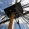
Hi again folks, another small update. I have started to dry assemble the mast components to check for fit, alignment etc. The following photo shows the start of the Fore Mast.
Thanks for looking in Dave and for your most kind comments - still learning quite a bit as I progress
-
 BANYAN got a reaction from dashi in HMB Endeavour by BANYAN - FINISHED - Artesania Latina - 1:60 - circa 1768
Tops
With the lower masts constructed, I have moved onto the tops and as you can see, my planking technique is improving but I have some way to go yet. I do not intend using plank joint trennels on the tops as the scale is much too small. I have now tried several different ways of simulating the caulking and have settled on using a 2B pencil rubbed along one edge of the plank as the best finish at this scale.
The trestle-trees are just loosely fitted and will be adjusted to their correct position when the tops are fitted to the masts. I have yet to do the trennels for the platforms.
It took me a while to determine the best technique to create the futtock deadeyes and straps. Eventually I realised that I could create the eye for the deadeye from brass wire. Soldering this closed is not such a problem as these deadeyes are black, and a coat of Raven Oil soon hides any char/scorch marks. I then flattened the tail using a pair of flat jaw pliers (no grip pattern on the inside of the jaws). Once the tail has been flattened and cut to length I drill a small hole for the hooks that will secure the futtock shrouds.
The completed top platforms are shown below along with the futtock deadeyes ready for mounting when I assemble the masts.
-
 BANYAN got a reaction from PeteB in HMB Endeavour by BANYAN - FINISHED - Artesania Latina - 1:60 - circa 1768
Rudder
The rudder is made from three pieces of walnut glued longitudinally and shaped to conform to the pattern depicted in Marquardt's drawings. The following picture shows the rudder fitted; however the chain rudder pendants have yet to be fitted. I'll do this after the rigging as they will be quite prone to damage.
The collar for the rudder is made from calico cloth which will eventually be treated with a diluted PVA solution stained a very pale/light grey and weathered to simulate canvas. In the following photo you can see where I am starting to clean the edges and touch-up the paint. This will all be second coated to give a uniform deeper colour.
-
BANYAN got a reaction from PeteB in HMB Endeavour by BANYAN - FINISHED - Artesania Latina - 1:60 - circa 1768
Ports and Hull Fixtures
The airing and loading ports were cut into the hull planks with a sharp chisel and the hinges applied. The port hinges are photo etched shim brass which have been blackened and glued with CA. These were drawn up in Corel Draw and etched by a contact in the Railway modelling world. I was quite pleased with most the etched pieces and will definitely use this process in future builds; maybe even try etching myself.
I decided to apply the hinges to the airing ports opposite to that normally fitted to most models. I have based this decision on intuition, but I should check this against contemporary models and references for accuracy. My thoughts were that these would have been used mainly in port where when the ship was laying into the wind, the wind would be funnelled into the port. This principle also works if the ports were opened in calm seas in the tropics where the ship's motion would funnel the wind into the ship as the port lid would open aft.
The gangway steps were made from a single length of walnut which was shaped by scraping with a profile cutter made from a hacksaw blade with a mould shape cut into it. Individual steps were then cut off to length and glued into place. The following photo shows the gangway steps, boat skids and the starboard sheets fairlead (with brass sheaves).
-
BANYAN got a reaction from PeteB in HMB Endeavour by BANYAN - FINISHED - Artesania Latina - 1:60 - circa 1768
Deck Planking
I have tried to remain true to scale with the planking. The size of planks in ships was determined by the availability of timber stock at the time, so I opted for something in the mid-range for a typical plank length in this era. The plank size I used was based on boards of 12 inches width by 25 feet long (actual), which at 1:60, equates to 5mm wide by 125mm long. This proved very convenient as the kit supplied deck 'Mukall' planking plank strips, were 0.5 x 5mm wide.
For the deck planking, I again opted for a 4 plank butt shift, centred from a slightly wider king plank. This was a relatively straight forward activity, and with her bluff bow, there was no need to worry about nibbing and joggling into a margin plank. I was not sure whether to use a waterway or not, but in the end decided not to, as at this scale it would have been a little too awkward (for my skills at that stage and as a first build). I now regret that decision, but I have learned a valuable lesson. I have not ruled out the option of a retro-fit just yet.
The mast holes were drilled at this stage. I had placed filler blocks of poplar pine between the bulkheads in these areas to provide additional support for the masts. These were pre-drilled and then redrilled under a very large mill working with ever increasing drill bit sizes until achieving the correct diameter. I used a protractor to determine the correct rake from the kit plans, and reconfirmed with Marquardt (based on dockyard drawing/plans). Dummy masts (dowels) and a digital angle level were used to ensure the masts were correctly raked and aligned (fore-to-aft) on the model.
The model is shown in her working cradle which is made from pool spaghetti (available at Clarke Rubber for the Aussies). This has proved a very versatile building cradle since completing the first layer of planking. I used the Amati keel holder during the assembly of the skeleton and first layer of planking.
-
BANYAN got a reaction from PeteB in HMB Endeavour by BANYAN - FINISHED - Artesania Latina - 1:60 - circa 1768
Wales and Anchor Lining
The wales were glued to the first layer of hull planking before applying the second layer. I used continuous run planks of the appropriate thickness which I butt jointed. I do not think that the owners/builders of a collier would have expended money on the Admiralty preferred anchor stock joinery. As the wales were to be painted, I did was not overly concerned with the joinery; a good sand and coat
of paint hid most of my poor quality joints .
The anchor lining and bolster were applied over the second layer planking and sanded down to be flush with the thickness of the
wales. The side view of plans and drawings provided with the kit are very misleading as this feature is, by the nature of a 2D drawing, shown flattened or fore-shortened as this feature is located at the start of the curvature of the hull. As such, the drawings do not truly reflect the actual curve imposed to these strakes.
To achieve the positioning and sweep of these planks, I temporarily fitted the anchor where it would ride when hoisted in and lashed to the fish davit; I then let the anchor swing through its path watching the end of the flukes as it swung after it would have been released from the davit to hang from the cathead.