Matrim
-
Posts
1,401 -
Joined
-
Last visited
Content Type
Profiles
Forums
Gallery
Events
Everything posted by Matrim
-
Hmm I would have thought EdT's Diana books would have had a better interior room plan than the Swan as it is at least the same size. Then again this Triton is much earlier than those. Allowing I have remembered correctly and this is the 1771 Triton the NMM holds several of these http://prints.rmg.co.uk/index.cfm?subSearchString=triton&event=catalogue.qsearch&searchString=1771 Plus they 'may' have appeared in Gardiners early frigates (or possibly Steel for that). Someone may have a copy of either so can give some more guidance on what went where as necessary. Joss
-
Done, give me a shout if you have problems finding them (they should appear in a download forum very close to this one)
-
Sorry gents, no scans of full pages of copyrighted books. 'Fair use' would utilise a subsection to prove whatever point you are trying to make, as opposed to the full image. Any full image would need to be accompanied by a 'reprinted by permission of ......' after having received permission to reprint. Thanks for your forbearance. Joss
-
Adjusted the title, feel free to switch to another name is you prefer
-
Great, you have been added and should be able to access all the relevant plans now. If you cannot then give me a shout. Joss.
-
We have to see the keel. Photos and evidence that it has been built. Basically the keel is the first thing that is built and you do not need any of the other plans until you have built the keel. This way we block all those (and there are many) who enthusiastically sign up with no intention of ever making the Triton and just want the plans. As an example look at other cross sections like Rafines http://modelshipworld.com/index.php?/topic/1321-triton-cross-section-148-by-rafine/
-
You have to build the keel to get access to the plans.
-
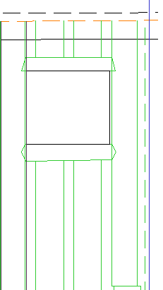
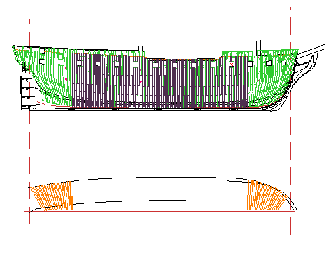
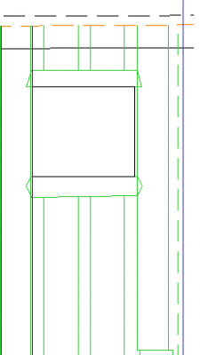
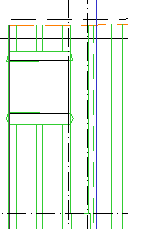
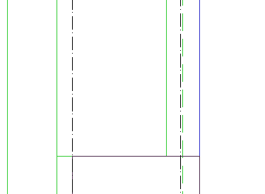
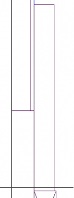
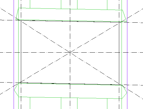
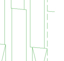
lol, thanks for that though that would require years more work and I have enough on my hands drawing up the ship... Anyway a brief update I have finished the outline of the square frames and drawn the cant frames in on the half breadth. I had to think about this. There are several methods for getting these drawn in and most seem to take one of two approaches. The first is that if you have the framing plan just take the lines from the relevant cant frames down to the half breadth at the keel and the cap rail and just draw them in. I tried this first but was not confident about all the copies of the framing plan (apart from the standard deviation of a CAD line of no width with a line that has width - you also have lines finishing in the air at gunports and unusual 'squiggles' at the top. The decider though was that I had drawn my own frames in and these did not match exactly the originals so it would seem unsafe to suddenly switch approaches at this point. One thing I had noticed was that the intervening lines of the traced half breadth (all the traces were on layers that I could show to 'validate' my own lines against the originals) followed the center lines of the double cant frames very closely. This then decided me on approach two. I used these centre lines and measured the width of the cant frames on the framing plan (all around 10.5 give or take a tenth of an inch) so the double frames were simple enough. Once the doubles were in I measured the gap between them at the keel, removed 21 and then divided by 3 to place the filler frames. This naturally was repeated at the cap rail position. Once in I threw some vertical constructors from the last of my square frames at either end to check there was no unexpected 'gap'. This shot shows the 'original' traced frames (in light green), The newly drawn square frames in purple and the cant frames in orange on the half breadth. The next job is to project my cant frame straight lines onto the main framing plan then I will do a stand alone frame plan.. Joss
-
Ordered, should be a nice Christmas present when it gets here
-
I love them so much I am buying the Folio Society editions of the Aubrey books (they have the entire set in hardback now with wonderful paper) (search page look for Patrick O'Brien http://www.foliosociety.com/search )
-
Its been a while since I have read it though it is on my shelf. If you are looking for a copy they are some still floating around though your best bet is an e-book at around £2. The book is okay for self-published. The author has looked at the various easily accessible sources (progress book) and picked all the relevant low hanging fruit on the ship. So he covers Hoste (in some detail) as there exists a biography, O'Brien's rejoining the ship in the adriatic as again there is a biography and interspersed the rest with details gleaned probably from the Navy Chronicle.I do not doubt he has looked at the musters but only a brief scan except perhaps the initial muster. There is some evidence he has picked and chosen from the captains logs as well. I am going into a lot more detail myself but once you avoid the 'low hanging fruit' you have to join the dots far more and investigate everything you can. As an example Bennett (the first Captain) has several reports in existing books (though not many) but looking through the NMM I picked up his court martial (which linked the 2nd captain Alexander Fraser to him as he sat on the court martial) and in his service history noted he served with Collingwood in the Americas. Now at the time he was serving with Collingwood, another Mid on the same ship also wrote a biography. Now he is not mentioned directly but that biography does give an impression of serving on that ship and what the other mids were like which covers Bennett and also provides potential explanations for Bennetts possible unwillingness to serve under Nelson. Now admittedly none of that is relevant directly to the ship but if more useful than a compilation of information gleaned from other sources and the amount of information you can grab by getting all the officer service histories or letters from.to the captains or even number crunching the musters to find desertion rates/where the crew came from are all things which are fascinating (to me) and not done here. For me (and this is just my opinion) he does not dig deep enough to make the book truly detailed and for a book covering such a large period it is very short. On the other hand he does bring into one location a lot of this surface information and if you are not able/willing to hunt for that then it would prove useful. I found 'Remember Nelso' a better read a book which covered a big section of the Amphions history, Gardiner covers more of the design details and why/where built arguments (not that Feather covers this). There are plenty of general history books which cover the Spanish treasure fleet action in some detail along most fictional books as Hornblower and O'Brian both have Sutton involved in their relevant re-writes of the action. Joss
-
That quote concerning US practice is so useful I will place it here as well (cheers Frolick) and a link to Frolicks discussion should anyone like to see the full http://modelshipworld.com/index.php?/topic/3272-the-two-possible-sterns-of-the-frigate-essex/
-
Roman Pm'd me an interesting question. Plus as I do not know the answer I thought I would stick it out here to see if anyone with more familiarity with British ship building practice could answer.. Roman My 'guess' back and Romans Response So anyone know? Since I got back from work I have since had a flick through Gardiner and though the practice is not everywhere it certainly can be seen enough to be termed widespread. I.e Hyperion class, Seringpatam and the USS President etc etc. I wonder whether the rigging setup defined the quarterdeck gunport placement and what would have been the British thought with regard to gas (no bean comments please) or exploding guns below... Joss
-
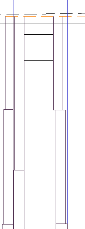
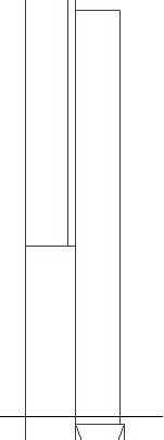
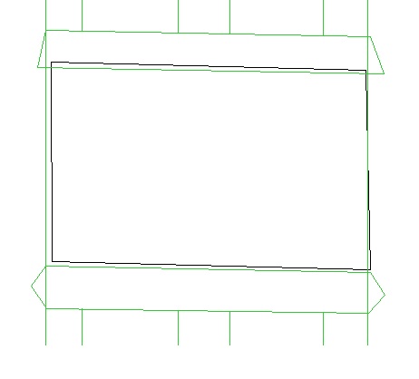
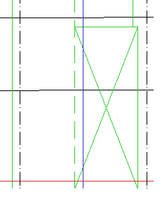
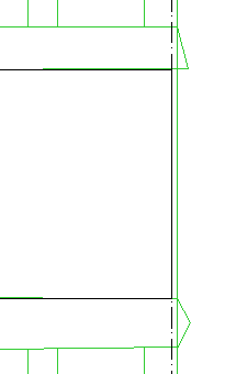
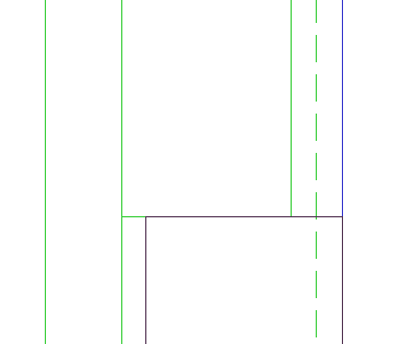
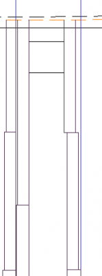
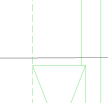
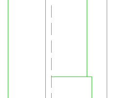
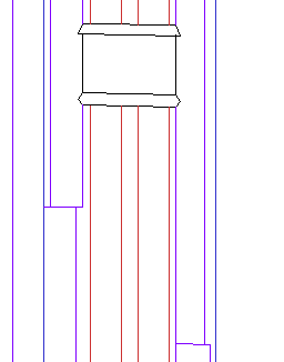
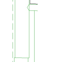
Thanks for any comments all. Time to move on with more general warblings. I re-arranged my methodology slightly as I rapidly realised my frames would need more work than I previously expected. Basically you have the choice of three options here (for the square frames) A - Keep the frames a fixed siding and completely vertical - gun ports would have to move to match the new frame locations. This is the simplest build option but is also the least historical (though I do ask myself who would even notice) B - Keep the frames a fixed siding and completely vertical but introduce some declining frame sidings where necessary to match the gun port locations as recorded from the plans C - Follow the historical framing plan Now I intended to utilise 'B' but found I needed so much declining sidings that I might just as well do 'C'. So this is what I switched to. To make this job easier I removed the square frame layer I had earlier produced and then generated a quick hand drawn picture to remind me of the frame locations (in this area of the ship the left of the frame would contain the lower or 1st, 3rd and toptimber and the right the floor, 2nd and 4th. My contract provided the relevant dimensions as follows for the midships area (9-G) Floor 13 inches 1st Futtock 13 inches 2nd Futtock 12 inches 3rd Futtock 11 inches 4th Futtock 10.5 inches Toptimber 9.5 at top of sides except when bordering a port in which case 11 So armed with this I can start Here is my working area. The frame I will be working on is Frame B The black square is the sized gun port. The green fixed lines are from the trace of the framing plan with the dashed line representing the framing plan station line. The purply line is my station line. So I start at the keel. Here I simply drew parallel constructions 13 inches from my station line as follows and then drew in the floor followed by the lower/1st futtock At this point I needed to return to the gun port which is bordered by the left hand side of this frame and here I drew a construction line This relates to the toptimber so the width bordering a port is 11 so a parallel soon provided the shape of the top timber Next up I looked at the 3rd. As always I returned to the framing plan As you can see (ignore the 'new' purple lower timber) that on the original plan the 3rd matched exactly the left side of the lower. So I placed a construction there and then paralleled a line at 11 inches - which is the 3rds width Now to the 2nd. As before I checked how the framing plan coped Here the left border is again exact. So I placed a vertical construction and then put a parralel out 12 inches and drew it in. Finally we have the 4th So here is the final frame with diminishing sidings. I shall be slowly following this process for the rest of the frames. Though time consuming (and I am not particularly looking forward to all the different thickness's of wood required when cutting the frames out - no more placing all parts of a frame on one piece of wood) this will have the historical thinning and lightening of the sides on the model and thus more weight in the centre lower section of the ship. Cheers, Joss
-
Nice wood colours
-
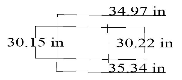
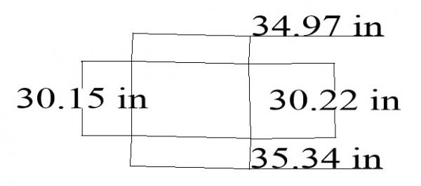
I would even say probable as far as distortion is occurred. The thing is the difference in dimensions is not slight. The Height is arguable at 1 inch but 4 inches for the width is not. Admittedly that is only 2.12mm but with these final measurements I was using the inward lines of both measurement points so the far right edge of the left side of the port and the far left edge of the right side of the port. Any other measurement point could add another mm and hence another couple of inches (coming close to the 38 gun ship port sizes) . The other thing is that all three plans with gunports agree with the width. If it was one then you could say problems with distortion. Cheers, Joss.
-
After a further investigation I have decided my gunport approach. I checked my own copy of steel and as Druxey states the provided port sizes are as follows (for the upper deck) Size 38 36 32 Deep 30'' 29'' 28'' Fore & aft 34'' 34'' 30'' Now I then re-measured all plans with gunports on (class amphion, amphion actual,framing plan) using the smallest possible width and the size came too for the framing plan 34'' wide and 29'' deep other plans 33'' wide and 28.5'' deep Now as the lines on the 'other plans' tend to be thicker this means the ship average is close enough to 34 by 29 which as seen above is the Steel width for 36 gun ships as opposed to 32. Considering the ships history I do not think this is difficult to explain. Firstly Steel is providing generalities over decades of ship building and not hard and fast rules and secondly if you look at the 32 gun ships as a whole they mainly tend to be 12 pdrs or less. The Amphion class was rare in that it is a 18pdr 32 gun ship so it makes sense to me for it to have ports equivalent in size with the 36 class which also mainly carried 18 pdrs. Otherwise the armament would be constrained compared to equivalent armed ships. Even if this assumption is incorrect my basic rule is that the ship plans are right and other data resources such as the contract or Steel can help confirm things but should not be taken in preference to consistent plan measurements without exceptionally good reason. Anyway that done back to the plans. Looking over my options I am using the frame as my default but rather than favour the bow side line of the stern side I am taking the midpoint and spreading the 34 inches over that. Equally for the horizontal sides I am taking the midpoint, splitting and then reapplying the correct angle. Once the sides have been marked I then added the sills using 6'' for the lower and 5'' for the upper before (in this case) adding some decrease in siding to match the original plan structure to cope with the new sized gunport. I will now start the long process of repeating this for all the other square frame gun ports. Cheers all, Joss
-
Cheers for the comment. Other people will probably give a better answer than I can but as the decks can sweep at quite an angle it would make no sense to have the gunports true horizontal as they would then be angled as to the deck the gun was being serviced from. If the ports were true horizontal then the gun would not always be able to cover all directions as the deck drop/rise would cause the cannon to 'touch' the gunport or alternately not be able to reach it at all. The sides would be vertical because the frames that erm framed them were vertical (and if they were not then the ship wrights would have a much worse time building the ship than they would coping with what are much smaller angled gunports). I doubt that is a very satisfactory answer though so we will see if anyone can provide a better one. Joss..
-
Great work. Plus you are so close to completing now... Joss
-
Cheers Druxey, I shall carry out some more validation against some of the other original plans tonight. Is that measurement frame to frame or would it include any 'interior' wood i.e gunport sill would reduce the height of the gap and could be around 2 inches plus any wood (if any was used) on the vertical. I will hit the books before carrying on further to see if I can resolve the discrepancy myself. Cheers, Joss.
-
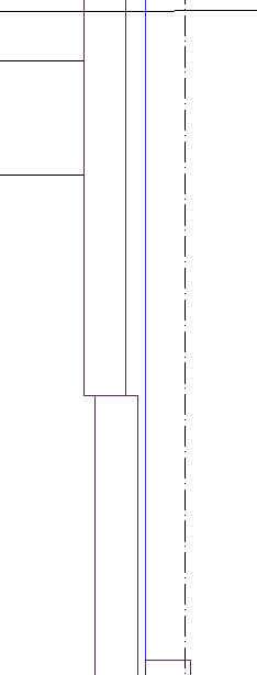
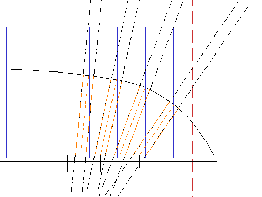
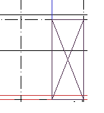
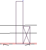
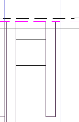
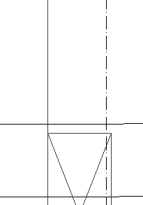
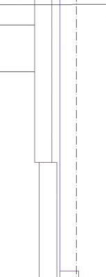
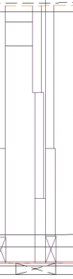
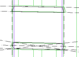
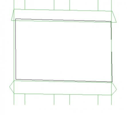
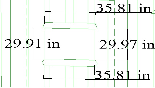
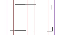
Time to move (slowly) onto the framing plan. I decided to not use the existing plan except as a template and then had to make a descision on the vexing question of whether to follow standard practice and having the siding decrease with each frame. On reflection that is beyond my ability so I will keep to equal sided frames except where an actual siding would enable the frame to better map the actual gun ports. Though this will make the construction easier it means there will be some more work to do in ensuring the framing plan adjustments do not upset the integrity of the design. First up I validated some numbers. My Proserpine contract lists the siding of the frames as follows Lower Futtocks between 9 and G sided 13 inch 9-13 + G- >= sided 12 inches Forward and aft 11.5 inches I then validated this against my own framing plan. Scaling up then down I measured each of the double frames to ensure they matched the contract above (which they did). Next up I drew in the square frames before calculating the gaps. i.e for the central frames the gap was 36.36 with 2 single frames if each is 13 inches then the three gaps would be 10.36/3 so 3.45 inches. When the frame sidings changed so does the required gaps. Another noticeable difference was the section of the hull where three single frames separated the two doubles. Once the frames were in it was time to check against the various gunports. For the purposes of the gunports the single frames do not usually form the sides so can be ignored (1 gunport was sided by a single but I will get to that later. The next point is that allowing for the drawing method the gunports themselves might not be exact. Measuring the gunports on the plan I was fairly happy that the width was approximately 35 inches for all the gunports. On my frame plan the measurements were as follows I marked the sternmost gunport of the square frames as I and worked forward from there Gunport CAD frames Original sheer I 39.36 35.28 II 39.36 35.47 III 38.36 36.17 IV 37.36 35.45 V 32.91 34.96 (bordered on right by a single frame) VI 36.60 35.21 VII 36.36 35.28 VIII 37.86 35.04 IX 39.36 35.62 As can be seen the sheer plan ports (with the noticeable exception of III) all hover around the 35 inch mark. The cad frames are both larger and generally more regular. A lot of this lies in the siding decreasing but it is also covered by the gaps making slight and increasing differences in size which incrementally upset measurements and slight movements in the station line. The adjusting sizes of the gunports as measured on the original sheer has been impacted somewhat by the measurement itself. As CAD lines are thin the thicker line drawn on the map (on the right hand side of the gunport) allows slight adjustments in size to occur. To resolve this I firstly adjusted the gunport width to exactly 35 inches with the right hand line 'losing out' I then either added diminishing sidings wherever it would push my lines badly off. Height wise the gunports appeared to consistently measure around 29.45 inches. So to start I needed to finally decide which lines would be used as my target gunports - the sheer square or the framing plan ports. Here is a shot of the I gunport two with the sheer port in black. And measurement for both Frame ports Sheer plan gunports Now the horizontal for this port is not true horizontal - using two vertical starts it matches 34 inch but measuring the full length of the line almost hits 35 (hence the discrepancy between this and the above width marks which followed the horizontal). There is nothing there really to make me prefer one over the other - something which was consistent over the other ports so I had to pick one. I decided in the end to use the sheer plan ports and not the framing ports. Now the next shot is of the sheer I port and the double and single frames in that area of the ship - this is also where the gap should be the worst as it is incrementally furthest away from the central double (0) frame. Now on the framing plan there are some large sidings adjustments as follows Sternwards Bowards So I shall replicate. My next job therefore is to ensure the gunports are all the correct size and bordered by frames. If anyone has anyone opinions as to gunports sizes or the best way to resolve this then please say. Anyway bye for now. Joss
-
You were just being courteous which is fine so it was not aimed at you. The problem with not deleting is that people wont necessarily read the warning on say page 32 and having seen foreign language posts on p30 or 31 will then think it is permitted. Equally editing every language post with a 'don't do this' is time consuming and defeats the purpose if the post is allowed to stand. Anyway I don't want to hijack your build log by branching so will stop talking about it. In a couple of weeks I can clear this and the original responses to clear the log up as well. Joss
-
Quick reminder that foreign language posts will be deleted on sight by moderators. Site rules state all posts should be in english. The odd word here or there is fine (and after all english is full of foreign words) but anything that cannot be ignored and needs to be translated is a no no. Sorry guys. Joss.
-
Interesting approach. The two reasons for doing them on model is firstly to avoid minor differences in placement which could cause the holes to be out of line with each other. Secondly the treenails help hold the model together and as glue fades over time this can be important. Still if you are only using them cosmetically then it matters less. Joss
-
Just finished both the mini-series and then the book(s) and I must say they were both magnificent. Most Napoleonic era fiction is of the 'heroic' mould with battles galore and fighting. Of the military authors only O'Brian has the ability to write more generally about the people and lifestyles as if the war was something that happened as opposed to the focus of their being. Then I found this. Golding (as ever) characterises the crew and passengers admirably and his handling of the various tensions and actions is exemplary. One thing I will say is that the series follows the book fairly closely but are both equally strong. Both are highly recommended....