Matrim
-
Posts
1,401 -
Joined
-
Last visited
Content Type
Profiles
Forums
Gallery
Events
Everything posted by Matrim
-
Aubrey was inspired by several officers of that period. Cochrane is the most well known and has at least three events that are notably tied to him. Other officers are also present for example Rowley in the Mauritius Command http://en.wikipedia.org/wiki/Josias_Rowley where O'Brien did not change the ship names or events at all except for Rowley being renamed Aubrey really Or Riou for encounters with icebergs http://en.wikipedia.org/wiki/Edward_Riou There are many others. Cochrane of course had the financial fraud, the Speedy story and there is another that I cannot remember of the top of my head [Edit Cochranes South American adventures]. People know Cochrane of course so like to expound on how he was the 'source'.
-
She is looking very nice. Plus turning some barrels is a nice extra touch. Joss
-
Does look missing. You do have the full frame plan though and since you have the lengths of both the floor and the second futtock you could lay cut outs of those on the complete plan and just mark of where the 4th futtock starts and thus get a fourth futtock. Joss
-
K, I am now deleting any posts which try and change the topic to point towards another author. This thread is for comments concerning Patrick O'Brian only and not any deep abiding loves for the Twilight series or Bolitho or bodice rippers or Janet and John or whatever. Keep on topic please.
-
Boxwoods a little to delicate for tree nails for me so well done for having the patience to draw them. I only used bamboo because of my rather cack-handed way of pulling them..
-
Beautifully done.
-
For the little man screen shot the image you like then you can shrink to size in an image program. Alternately get a photograph of yourself and do the same (and really freak people out)
-
Things are progressing nicely and I am currently on the 'smart' plans. I wont upload the keel/false keel parts plan as that is quite simple and thus not that exciting. Here though is the smart sheer plan. I have also finally worked out how to get a viewable image out of turbocad. Save as a pdf. Open in pdf reader and screenshot it.. Next week I plan on starting on the framing plan. Joss

-
Looks good. Plus well done for the skill to build off model. I was never accurate enough and had to build in situ myself Joss
-
Excellent quality, up there with John0868.. Joss
-
Thanks both for the comments
-
In paper mode how do I get a line with an arrow so I can annotate my plan?? Joss
-
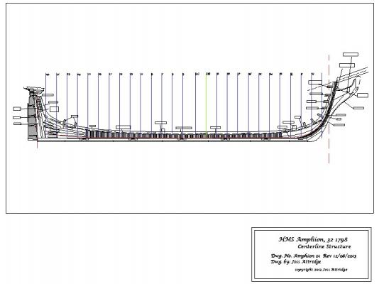
Without further ado here is the keel master. As before I am utilising EdT's plan styles because they are just so stylish. and since I cannot appear to get turbo cad to save it in a readable format for the web As stated before onto the construction plans for the keel/false keel next Joss

-
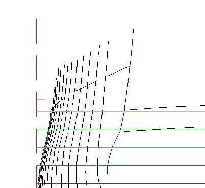
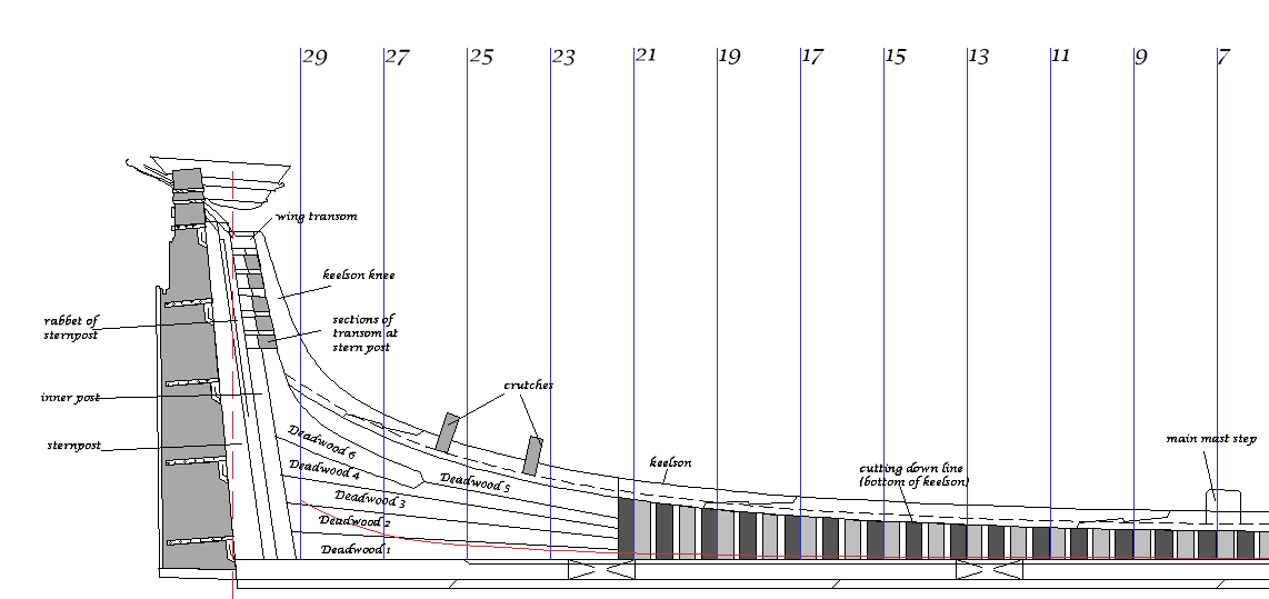
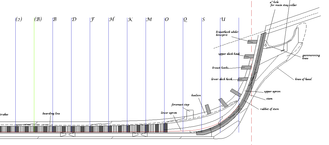
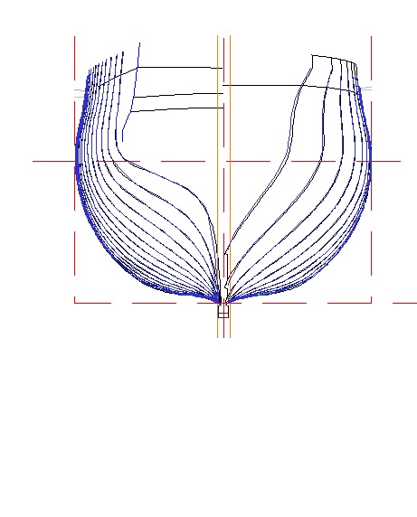
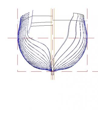
Just a quick update. The plan is redone and faired and I am ready to start (back) on the primary drawings again. Keeping the original plan lines on a hidden layer proved useful in checking the validity of my completed plan as below. Here the new station lines are in blue and the original station lines in black Last time through I started on separate completion plans for each section (i.e frames, keel etc etc) this time I am getting the basics correct on the primary plan and then simplifying to work on each new plan. Here is my working copy of the keel master plan. All I have done so far is copy the information from the main plan and started stripping down the info to what I want to show on the plan. No doubt there will be some adjustments I notice that will need to be mimicked back on the main plan but I should be in a better state to undertake this. Hopefully I will get the smart version of the Keel Master out of the way by next week then can re-do the keel, false keel, stem, bow, keelson individual break out plans. Joss

-
Nothing is worse than trying to hurry and getting the treenail stuck because you have been to keen to 'progress' it. Then it snaps. Then you realise the bits that are left are too small to be useful Joss
-
That is allowed, You are not allowed to post up the actual plans they are restricted access for a reason. Joss
-
The treenails will help keep the model together if the glue starts failing years down the line. Good work Joss
-
Have a great day
-
Looks amazing, very impressive Joss
-
Thanks for the comment, I find the cad work relaxing (at least when I believe I am working correctly that is) Joss
-
For me natural and possibly Colonial Maple though Golden Oak is an auto-disqualifiy if it 'patterns' like that when used.. Joss
-
Doing a bunch of treenails can sap your soul. Russ's approach is better but requires some discipline to remember to do so. I tried pulling treenails whilst watching television. You break a few as you are paying less attention but you can get a useable pile done quickly without too much frustration. Joss
-
Great as always and I like the mini-tool for holding the blocks steady while you rig them. It's these little things that can make a frustrating job that little bit easier.. Joss
-
Looking good, I never had the confidence to use paper and was happy with my 'paste' approach ala John0868 but that in itself caused a need for excessive sanding later so swings and roundabouts really.. Joss
-
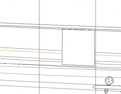
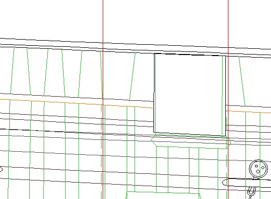
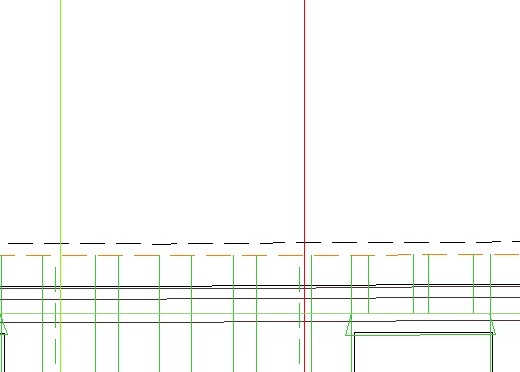
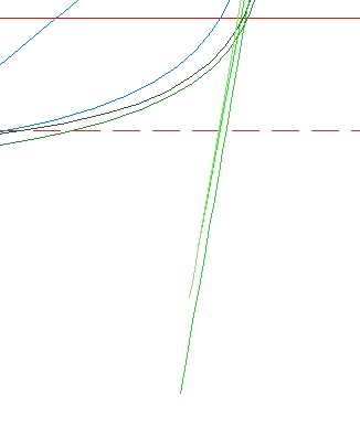
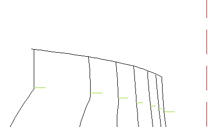
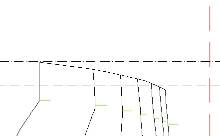
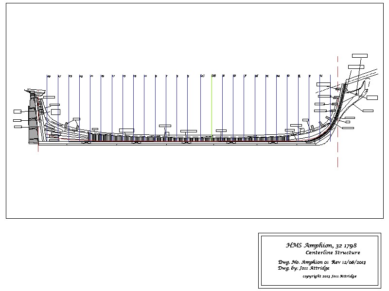
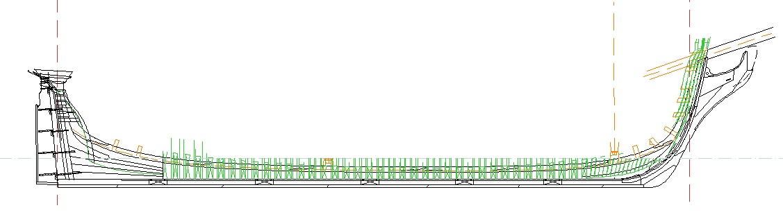
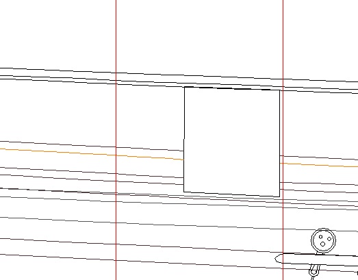
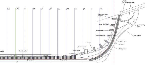
Time for another un-thrilling update! I have just completed drawing in the new waterlines and as an expression of my greater confidence have drawn them at 3ft below the wale and 1.5 ft above (in the original plans I went for 2 ft and 1 ft respectively which just added extra work and did not allow the auto curve CAD functions to work as cleanly as they could). Rather than go into exhaustive detail Wayne's tutorial covers this nicely. I did have to make a couple of leaps of faith though. Which I shall detail here just in case they are invalid leaps. First up when working above the wale towards the rear of the ship you will notice that most plan sets suddenly stop 'bending' the lines to the keel and start sticking straight out as so - Below the wale the waterline should start at the rabbet line. Above the keel this does not exist. Instead I used the handy stern line (here in blue) coupled with one of the rear dotted plan lines from the sheet as my 'start' point above though I am not entirely certain what this relates to - I don't think (what do I know) that this will affect anything later on as other superstructure builds up this. Whatever else you do don't forget and treat this like a station line though as that will really damage your hull shape.. The other area is in the placement of the cap rail. annoyingly enough is not the highest rail on the ship but (at the rear) the following (in the light brown colour) The superstructure above this is not part of the standard framing as can be seen if I switch on my underlying frames trace. In the center of the ship I am using the bottom dotted line. Mainly because again that is where my frame plan frames complete. At the bow I was confronted with more of a conundrum. Here the frames clearly end at the upper rail but when transposing horizontal constructions across the lines completed at the following (note the little horizontal green lines which indicate this point) The lines above this suddenly shoot vertical so looking at my plans I drew a construction from the top of the timberheads where they crossed a station line and then threw a couple of horizontal construction lines off. This appears to match the vertical limit of the body plan lines on the body plan. My problem is that the timberheads (if I remember correctly) were an extension of the frames. So my problem is should I use that line as the cap rail on the sheer or the cap rail as it exists for the majority of the frames. - The timberheads are after all intermittent and do not occur on every frame.. Anyone this stage is fast so if anyone has any criticism of the approach then please say before I get back on to it. Thanks for reading.. Joss