Mike 41 Posted July 24, 2023 Share #1 Posted July 24, 2023 Ship History: His Majesty Yacht (HMY) Fubbs was laid down at Greenwich shipyards by Phineas Pett in 1682. By Royal Navy standards yachts would be the size of a typical harbor dispatch vessel or lightly armed gunboat. HMY Fubbs sported a keel length of only 63’ with at a specified 148 tons fully loaded. With a 21’ breadth and only 9’6” depth in hold these small ships carried a crew of up to 30 and could be armed with 8 – 12 3 pounders. Royal Yacht duties primarily consisted of tending to the affairs of the royal household. Charles II must have enjoyed yacht class vessels as he had 23 of them during his reign – more than any other English king. HMY Fubbs was the most lavish of his fleet of Royal Yachts. Visually, the hull of a Royal Yacht has the look of a 6th rate but is more akin to a ketch-rigged sloop. As such, she has a mizzen mast that passes through the small great cabin and no true orlop deck at all. As will be shown later, the stern ports are too close to the waterline and are not actually accessible from inside the ship. What look like stern quarter galleries are more like quarter badges. Most contemporary modelers and many artists tend to imagine HMY Fubbs as a larger ship than it really is due to the illusion created by the artistic style of the ship. Charles II employed well known Baroque period artists Van de Veldes younger and senior. Their artwork had a direct influence on the highly decorated HMY Fubbs. HMY Fubbs was named after the mistress of Charles II, the Duchess of Portsmouth, Louise de Keroualle. “Fubbs” was the nickname for Charles II mistress with the meaning of a chubby contemptuous child. HMY Fubbs remained in service for more than 80 years before being broken up in 1781. During that time, it went through 2 refits. One in 1701 and again in 1724. During the 1724 refit, most of her carvings were salvaged and replaced by painted frieze work. The Model: The concept of the stern section was developed by Mike Shanks and DocBlake. They acquired the drawings and reference material used for the HMY Fubbs 1725 rebuild kit from Bob Hunt at Lauck Street Shipyard. Mike Shanks created the drawings using this and other resources. Mike has a well-equipped shop with laser, CNC, and 3D printing capabilities which he used to build the prototype for the model. Jodie Grein developed the artwork and 3D drawings for the décor, Mike used the artwork along with all the parts for ten kits. This model is made from one of the kits. Weasel Works is a private club, and the kits are not available to the public. The frames for the section are a style used by Portia Takakjian in the 1725 rebuild drawings she made, and Bob Hunt used in his kit. Although not historically correct they produced an accurate representation of the hull. Kit Contains: This is a few photos of the parts included in the kit. Archi, CiscoH, GrandpaPhil and 4 others 7 Quote Previous Builds: USS Pennsylvania - (1837) Scale: 1:64 Cross Section Continental Galley Washington 1776 Link to comment Share on other sites More sharing options...
Mike 41 Posted July 24, 2023 Author Share #2 Posted July 24, 2023 Section Limits: This set of five drawings show the size of the model from different viewpoints. The model is Navy Board Style with stub masts and no rigging.  mtaylor, JpR62, bruce d and 3 others 5 1 Quote Previous Builds: USS Pennsylvania - (1837) Scale: 1:64 Cross Section Continental Galley Washington 1776 Link to comment Share on other sites More sharing options...
allanyed Posted July 25, 2023 Share #3 Posted July 25, 2023 (edited) 18 hours ago, Mike 41 said: This model is made from one of the kits. Weasel Works is a private club, and the kits are not available to the public. Hi Mike, I may be misinterpreting but are you saying the kit in the photos are not available to MSW members? Thanks Allan Edited July 25, 2023 by allanyed Mike 41 and mtaylor 2 Quote PLEASE take 30 SECONDS and sign up for the epic Nelson/Trafalgar project if you would like to see it made into a TV series. Click on http://trafalgar.tv There is no cost other than the 30 seconds of your time. THANK YOU Link to comment Share on other sites More sharing options...
Chuck Posted July 25, 2023 Share #4 Posted July 25, 2023 Mike...Looking great. Cant wait to see you start making progress. I have seen some of Mike Shanks progress on the development of this project...happy you started a build log here. Allan...this is just a small group of model builders that got together and made a few kits for their little group. It is not a commercial kit. There are about a half dozen participants, maybe a few more. I think Pat...Banyan is also building one but I am not sure. Hopefully he will start a log as well. Chuck allanyed, mtaylor and Mike 41 3 Quote Chuck Passaro - MSW Admin Sloop Speedwell - POF scratch Block Island Boat - POF scratch HMS Winchelsea - POB scratch build HM Cutter Cheerful - POB scratch build Royal Barge - POF scratch Medway Longboat- POF Scratch SYREN SHIP MODEL COMPANY Link to comment Share on other sites More sharing options...
druxey Posted July 25, 2023 Share #5 Posted July 25, 2023 For many years there has been confusion over the different versions of Fubbs. The one you show here is the 1724 rebuild, not the 1682 original Fubbs. The original had a straight cutwater, more vertical stern post and a taller, rounded tafferel. The inboard arrangements were very different than that of the rebuild. That the above statements are accurate is part of the result of several years research by the Stuart Yacht Research Group, a small international group of historians and model-makers of which I happen to be a member. mtaylor, Doreltomin, Hubac's Historian and 1 other 4 Quote Be sure to sign up for an epic Nelson/Trafalgar project if you would like to see it made into a TV series http://trafalgar.tv Link to comment Share on other sites More sharing options...
Mike 41 Posted July 25, 2023 Author Share #6 Posted July 25, 2023 Hi Druxey, Our focus is on building a nice-looking model using modern building methods. We are not naval historians, just a few old guys that enjoy building model ships as a hobby. We used Portia Takakjian’s as a resource for the structural components of our model. Has the Stuart Yacht Research Group published their findings on the 1682 version of the ship? I would be interested in seeing the original drawings of the ship. mtaylor 1 Quote Previous Builds: USS Pennsylvania - (1837) Scale: 1:64 Cross Section Continental Galley Washington 1776 Link to comment Share on other sites More sharing options...
druxey Posted July 25, 2023 Share #7 Posted July 25, 2023 Mike: There are no contemporary draughts (I wish!), just a van de Velde painting, a copy of another van de Velde, now lost, and a v de V drawing of 'de fob'. There is also a contemporary model in private hands that is an 'Admiralty' style model that we have identified as Fubbs. The findings of the SYRG will get published, but the manuscript is still in preparation with no date yet set. allanyed, Mike 41, mtaylor and 1 other 4 Quote Be sure to sign up for an epic Nelson/Trafalgar project if you would like to see it made into a TV series http://trafalgar.tv Link to comment Share on other sites More sharing options...
Mike 41 Posted July 25, 2023 Author Share #8 Posted July 25, 2023 Druxey: Thanks for the information. We are not planning on building another Fubbs model, but I find the ship very interesting. allanyed, druxey and mtaylor 3 Quote Previous Builds: USS Pennsylvania - (1837) Scale: 1:64 Cross Section Continental Galley Washington 1776 Link to comment Share on other sites More sharing options...
Mike 41 Posted July 26, 2023 Author Share #9 Posted July 26, 2023 (edited) Frames: It has been a while since I built a kit and the first time, I used laser cut frames. The large scale 1:24 made the parts easy to handle the eight pieces are joined with lap joints Making them very easy to assemble, with the exception of frame #25 the forward frame. It was cut using a CNC machine and uses scarph joints that fit perfectly together. After removing the frames from the shipping box, I sorted the frames. Each part has the frame number etched on the aft side of the frame making the orientation easy to maintain. The bevel lines were also etched into the frame parts also. After sorting the parts I bundled them by frame number and divided them into five stacks. Divide & Conquer LOL. Removing the char was not too bad using a spindle sander, but using the port on the machine for the vacuum left a lot of dust in the air so I clamped the hose about a quarter inch off the spindle that removed almost all the dust. I assembled the frames by placing the frame drawing on a sheet metal plate and using magnets to hold the parts in place while the glue dried. When the glue dried, I formed a vertical stack to check the bevels. Progress photos: Edited July 26, 2023 by Mike 41 JeffT, mtaylor, Chuck and 6 others 9 Quote Previous Builds: USS Pennsylvania - (1837) Scale: 1:64 Cross Section Continental Galley Washington 1776 Link to comment Share on other sites More sharing options...
Hubac's Historian Posted July 27, 2023 Share #10 Posted July 27, 2023 Magnet clamps? WOW! Such a cool idea! Mike 41 and mtaylor 2 Quote We are all works in progress, all of the time. Link to comment Share on other sites More sharing options...
Mike 41 Posted July 28, 2023 Author Share #11 Posted July 28, 2023 (edited) Frames continued: When Mike Shanks assembled the hull, he used a vertical stacking system. He described ever step with detailed photos and easy to understand instructions. The prototype went together quite well, all the frames are square and level. That being said, I am more comfortable with a horizontal build using a jig I have used for many years. I made a vertical stack as a dry run to check the bevels and general alignment. Everything looked good. I left the keel open ended. There is no space between the frames, and it is hot and humid in Myrtle Beach which adds to the expansion / contraction problem. It is easier to trim the keel than rework the frames. I added spacers at the top of the frames, with centerlines to help with the frame alignment with a string line, level and square as each frame is added. A few words about the jig I am using. I designed and built this one in 2012 and have used it for many models. If anyone is interested in the jig, I will post a PDF file here. Thanks for looking in on the build log, any comments are welcome. Mike Progress photos: Edited July 28, 2023 by Mike 41 Removed duplicate post. JpR62, Chuck, Archi and 5 others 8 Quote Previous Builds: USS Pennsylvania - (1837) Scale: 1:64 Cross Section Continental Galley Washington 1776 Link to comment Share on other sites More sharing options...
gjdale Posted July 29, 2023 Share #12 Posted July 29, 2023 17 hours ago, Mike 41 said: I designed and built this one in 2012 and have used it for many models. If anyone is interested in the jig, I will post a PDF file here. I'm sure many of us would be interested Mike. mtaylor 1 Quote Grant ____________________________________________________ Current builds: African Queen - Radio Control / Live Steam Previous builds: The Shipyard at Foss' Landing (Diorama), Hannah - Ship in a Bottle, NRG Capstan Project, 1869 Allerton Steam Pumper, Medway Longboat , Alfa Romeo Spider Gran Touring (Pocher) , Da Vinci Flying Machine, 1949 Chris Craft 19' Racing Runabout - Dumas - Radio, Bomb Vessel Granado, 1742 - Cross Section - Scratchbuild, HMS Victory (Mamoli 1:90), Cutty Sark, Armed Pinnace, Bounty, Santa Maria At another place: Stephenson's Rocket (OcCre 1:24) (click the title to follow the link) In the Gallery: Lancia Armata 1803, Bomb Vessel Granada, 1742 Cross Section, 1949 Chris Craft 19' Racing Runabout Link to comment Share on other sites More sharing options...
Mike 41 Posted July 29, 2023 Author Share #13 Posted July 29, 2023 4 hours ago, gjdale said: I'm sure many of us would be interested Mike. Hi Grant, this is a copy of the jig (Building Board) I am using. Mike Building Board.pdf Matt D, gjdale, allanyed and 1 other 4 Quote Previous Builds: USS Pennsylvania - (1837) Scale: 1:64 Cross Section Continental Galley Washington 1776 Link to comment Share on other sites More sharing options...
navarcus Posted July 30, 2023 Share #14 Posted July 30, 2023 Portia Takakjian ignited the single-foothook HMY Fubbs fire (as rebuilt 1724) 33 years ago. Romero wrote a great book a little later and Bob Hunt made 30 nice kits after that. Some kit-maker needs to step up and make the WW guys a worthwhile offer. Mike 41, mtaylor and CiscoH 3 Quote Link to comment Share on other sites More sharing options...
Mike 41 Posted August 1, 2023 Author Share #15 Posted August 1, 2023 (edited) The hull: After the frames were assembled, I glued them in place on the keel using a string line to keep the frames centered, clamps to align the internal bevels and a small level on top of the spacers. The bottom of the frames required trimming at the start of the dead wood, it is easy to do by measuring and trimming each frame before gluing it in place. After the basic hull was complete, I removed the top spacers and used a hand grinder with a flapper wheel to even out the frames. Progress photos: Edited August 1, 2023 by Mike 41 Chuck, CiscoH, GrandpaPhil and 1 other 4 Quote Previous Builds: USS Pennsylvania - (1837) Scale: 1:64 Cross Section Continental Galley Washington 1776 Link to comment Share on other sites More sharing options...
Mike 41 Posted August 9, 2023 Author Share #16 Posted August 9, 2023 The Stern Framing continued. This is a few more progress photos of the stern. JpR62, Archi, Chuck and 5 others 8 Quote Previous Builds: USS Pennsylvania - (1837) Scale: 1:64 Cross Section Continental Galley Washington 1776 Link to comment Share on other sites More sharing options...
Mike 41 Posted August 11, 2023 Author Share #17 Posted August 11, 2023 The Stern Framing continued. These photos show the planking of the stern and finished framing. gjdale, bruce d, ccoyle and 4 others 7 Quote Previous Builds: USS Pennsylvania - (1837) Scale: 1:64 Cross Section Continental Galley Washington 1776 Link to comment Share on other sites More sharing options...
DocBlake Posted August 11, 2023 Share #18 Posted August 11, 2023 Looking good, Mike! Archi and Mike 41 2 Quote Dave Click on images in posts to view them in full resolution! Click on the builds below and link to the log. Current Builds: -Gaff-Rigged Sloop, 1/4 Scale (3" = 1') -Chapman Water Hoy 1768 by DocBlake - Scratch Build - 1:48 scale -Hannah - 1:32 scale, Scratch-Built Plank-on-Frame Admiralty style -Generic Sharpie by DocBlake. 3/4" = 1' scale. NRG plans. -Fair American 1780 by DocBlake - Lauck Street Shipyard - 1/48 scale - POF -Independence 1775 by DocBlake - Artesania Latina - 5/16" scale -HMS Triton Cross Section by DocBlake - 1/24 scale Completed Builds: -Bomb Vessel Granado 1742 Cross Section - 1:32 Scale Scratch Build -British Capstan circa 1777 by DocBlake - FINISHED - 1:16 Scale -HMS Blandford - Cross Section - Scratch Build -1/32 Scale -17th Century Battle Station by DocBlake - HMS Mordaunt - 1:32 -17th Century Naval Cannon - 1:12 Scale -Royal Navy Ship of the Line Cross Section by DocBlake - (Mamoli's "Constitution") - 1:93 scale -Armed Virginia Sloop 1768, 1/48 scale. -Virginia Pilot Boat "Swift", 1805, 1/50 scale -18th Century Naval Battle Station, 1/24 scale -Armed Virginia Sloop 1768 "Patrick Henry", 1/32 scale, Lauck Street Shipyard, POF, Admiralty Style. Link to comment Share on other sites More sharing options...
Mike 41 Posted August 14, 2023 Author Share #19 Posted August 14, 2023 Kellson & Waterway Limber Boards. The keelson was soaked in hot water and bent to fit the curvature of the frames. I used glue and brass wire pins to secure the keelson to the frames. The limber boards were soaked in hot water and clamped to the keelson to dry. When dry I used spacers between them and the keelson and glued and pined them in place. Beckmann, Archi, CiscoH and 2 others 5 Quote Previous Builds: USS Pennsylvania - (1837) Scale: 1:64 Cross Section Continental Galley Washington 1776 Link to comment Share on other sites More sharing options...
Mike 41 Posted August 22, 2023 Author Share #20 Posted August 22, 2023 Great Cabin Floor. This post shows the placement of the mast step, interior lining of the stern timbers and placement of the great cabin floor. The floor has not been attached to the deck clamps until the support columns art in place. Progress photos: CiscoH, DocBlake, gjdale and 4 others 7 Quote Previous Builds: USS Pennsylvania - (1837) Scale: 1:64 Cross Section Continental Galley Washington 1776 Link to comment Share on other sites More sharing options...
DocBlake Posted August 22, 2023 Share #21 Posted August 22, 2023 Awesome work, Mike! Ryland Craze, Mike 41 and Archi 3 Quote Dave Click on images in posts to view them in full resolution! Click on the builds below and link to the log. Current Builds: -Gaff-Rigged Sloop, 1/4 Scale (3" = 1') -Chapman Water Hoy 1768 by DocBlake - Scratch Build - 1:48 scale -Hannah - 1:32 scale, Scratch-Built Plank-on-Frame Admiralty style -Generic Sharpie by DocBlake. 3/4" = 1' scale. NRG plans. -Fair American 1780 by DocBlake - Lauck Street Shipyard - 1/48 scale - POF -Independence 1775 by DocBlake - Artesania Latina - 5/16" scale -HMS Triton Cross Section by DocBlake - 1/24 scale Completed Builds: -Bomb Vessel Granado 1742 Cross Section - 1:32 Scale Scratch Build -British Capstan circa 1777 by DocBlake - FINISHED - 1:16 Scale -HMS Blandford - Cross Section - Scratch Build -1/32 Scale -17th Century Battle Station by DocBlake - HMS Mordaunt - 1:32 -17th Century Naval Cannon - 1:12 Scale -Royal Navy Ship of the Line Cross Section by DocBlake - (Mamoli's "Constitution") - 1:93 scale -Armed Virginia Sloop 1768, 1/48 scale. -Virginia Pilot Boat "Swift", 1805, 1/50 scale -18th Century Naval Battle Station, 1/24 scale -Armed Virginia Sloop 1768 "Patrick Henry", 1/32 scale, Lauck Street Shipyard, POF, Admiralty Style. Link to comment Share on other sites More sharing options...
Mike 41 Posted August 26, 2023 Author Share #22 Posted August 26, 2023 (edited) Great Cabin Floor. The hanging knees were added next along with the support pillars. The framing for the small section of the quarter deck will be added next. Edited August 26, 2023 by Mike 41 gjdale, Archi, JeffT and 2 others 5 Quote Previous Builds: USS Pennsylvania - (1837) Scale: 1:64 Cross Section Continental Galley Washington 1776 Link to comment Share on other sites More sharing options...
DocBlake Posted August 27, 2023 Share #23 Posted August 27, 2023 Great progress, Mike. She’s looking good! Mike 41 1 Quote Dave Click on images in posts to view them in full resolution! Click on the builds below and link to the log. Current Builds: -Gaff-Rigged Sloop, 1/4 Scale (3" = 1') -Chapman Water Hoy 1768 by DocBlake - Scratch Build - 1:48 scale -Hannah - 1:32 scale, Scratch-Built Plank-on-Frame Admiralty style -Generic Sharpie by DocBlake. 3/4" = 1' scale. NRG plans. -Fair American 1780 by DocBlake - Lauck Street Shipyard - 1/48 scale - POF -Independence 1775 by DocBlake - Artesania Latina - 5/16" scale -HMS Triton Cross Section by DocBlake - 1/24 scale Completed Builds: -Bomb Vessel Granado 1742 Cross Section - 1:32 Scale Scratch Build -British Capstan circa 1777 by DocBlake - FINISHED - 1:16 Scale -HMS Blandford - Cross Section - Scratch Build -1/32 Scale -17th Century Battle Station by DocBlake - HMS Mordaunt - 1:32 -17th Century Naval Cannon - 1:12 Scale -Royal Navy Ship of the Line Cross Section by DocBlake - (Mamoli's "Constitution") - 1:93 scale -Armed Virginia Sloop 1768, 1/48 scale. -Virginia Pilot Boat "Swift", 1805, 1/50 scale -18th Century Naval Battle Station, 1/24 scale -Armed Virginia Sloop 1768 "Patrick Henry", 1/32 scale, Lauck Street Shipyard, POF, Admiralty Style. Link to comment Share on other sites More sharing options...
Mike 41 Posted September 5, 2023 Author Share #24 Posted September 5, 2023 (edited) Quarterdeck Framing A small section of the quarterdeck for the entre to the great cabin. I glued the floor in place and trimmed the frames. Edited September 6, 2023 by Mike 41 Image was upside down. Archi, CiscoH, dvm27 and 1 other 4 Quote Previous Builds: USS Pennsylvania - (1837) Scale: 1:64 Cross Section Continental Galley Washington 1776 Link to comment Share on other sites More sharing options...
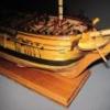
Mike 41 Posted September 6, 2023 Author Share #25 Posted September 6, 2023 (edited) MikeS reminded me I should not have glued the floor in place before the exterior planking so it would not get dirty with sawdust. No damage was done, just some extra work. Exterior Planking The exterior planking is typical with the exception of a slot for the main and mizzen masts channels. The planking is Maple, and the wales and channel filler pieces are Walnut which makes a nice contrast. Progress photos. Edited September 6, 2023 by Mike 41 ccoyle, gjdale, CiscoH and 2 others 5 Quote Previous Builds: USS Pennsylvania - (1837) Scale: 1:64 Cross Section Continental Galley Washington 1776 Link to comment Share on other sites More sharing options...
Mike 41 Posted September 7, 2023 Author Share #26 Posted September 7, 2023 Great Cabin Paneling The great cabin paneling is cherry with lines etched to represent individual boards. The five panels were easy to install. I used a router bit in a Dremel tool to cut the window openings, it was fast and required using a file for cleanup work. Progress photos gjdale, CiscoH, Beckmann and 1 other 4 Quote Previous Builds: USS Pennsylvania - (1837) Scale: 1:64 Cross Section Continental Galley Washington 1776 Link to comment Share on other sites More sharing options...
Mike 41 Posted September 13, 2023 Author Share #27 Posted September 13, 2023 Poop Deck The poop deck clamps were installed next. The deck framing was constructed in three sections to allow viewing of the great cabin interior. The bulkhead break was assembled and set in place to verify elevations. Progress photos: DocBlake, ccoyle, rlwhitt and 3 others 5 1 Quote Previous Builds: USS Pennsylvania - (1837) Scale: 1:64 Cross Section Continental Galley Washington 1776 Link to comment Share on other sites More sharing options...
DocBlake Posted September 13, 2023 Share #28 Posted September 13, 2023 Great progress, Mike! She's looking great. Quote Dave Click on images in posts to view them in full resolution! Click on the builds below and link to the log. Current Builds: -Gaff-Rigged Sloop, 1/4 Scale (3" = 1') -Chapman Water Hoy 1768 by DocBlake - Scratch Build - 1:48 scale -Hannah - 1:32 scale, Scratch-Built Plank-on-Frame Admiralty style -Generic Sharpie by DocBlake. 3/4" = 1' scale. NRG plans. -Fair American 1780 by DocBlake - Lauck Street Shipyard - 1/48 scale - POF -Independence 1775 by DocBlake - Artesania Latina - 5/16" scale -HMS Triton Cross Section by DocBlake - 1/24 scale Completed Builds: -Bomb Vessel Granado 1742 Cross Section - 1:32 Scale Scratch Build -British Capstan circa 1777 by DocBlake - FINISHED - 1:16 Scale -HMS Blandford - Cross Section - Scratch Build -1/32 Scale -17th Century Battle Station by DocBlake - HMS Mordaunt - 1:32 -17th Century Naval Cannon - 1:12 Scale -Royal Navy Ship of the Line Cross Section by DocBlake - (Mamoli's "Constitution") - 1:93 scale -Armed Virginia Sloop 1768, 1/48 scale. -Virginia Pilot Boat "Swift", 1805, 1/50 scale -18th Century Naval Battle Station, 1/24 scale -Armed Virginia Sloop 1768 "Patrick Henry", 1/32 scale, Lauck Street Shipyard, POF, Admiralty Style. Link to comment Share on other sites More sharing options...
Mike 41 Posted September 19, 2023 Author Share #29 Posted September 19, 2023 (edited) Settee The settee was built next. The construction is fairly simple. This is a few photos of the assembly. Edited September 20, 2023 by Mike 41 Image upside down DocBlake, gjdale, Archi and 1 other 4 Quote Previous Builds: USS Pennsylvania - (1837) Scale: 1:64 Cross Section Continental Galley Washington 1776 Link to comment Share on other sites More sharing options...
DocBlake Posted September 19, 2023 Share #30 Posted September 19, 2023 Awesome work! Quote Dave Click on images in posts to view them in full resolution! Click on the builds below and link to the log. Current Builds: -Gaff-Rigged Sloop, 1/4 Scale (3" = 1') -Chapman Water Hoy 1768 by DocBlake - Scratch Build - 1:48 scale -Hannah - 1:32 scale, Scratch-Built Plank-on-Frame Admiralty style -Generic Sharpie by DocBlake. 3/4" = 1' scale. NRG plans. -Fair American 1780 by DocBlake - Lauck Street Shipyard - 1/48 scale - POF -Independence 1775 by DocBlake - Artesania Latina - 5/16" scale -HMS Triton Cross Section by DocBlake - 1/24 scale Completed Builds: -Bomb Vessel Granado 1742 Cross Section - 1:32 Scale Scratch Build -British Capstan circa 1777 by DocBlake - FINISHED - 1:16 Scale -HMS Blandford - Cross Section - Scratch Build -1/32 Scale -17th Century Battle Station by DocBlake - HMS Mordaunt - 1:32 -17th Century Naval Cannon - 1:12 Scale -Royal Navy Ship of the Line Cross Section by DocBlake - (Mamoli's "Constitution") - 1:93 scale -Armed Virginia Sloop 1768, 1/48 scale. -Virginia Pilot Boat "Swift", 1805, 1/50 scale -18th Century Naval Battle Station, 1/24 scale -Armed Virginia Sloop 1768 "Patrick Henry", 1/32 scale, Lauck Street Shipyard, POF, Admiralty Style. Link to comment Share on other sites More sharing options...

Recommended Posts
Join the conversation
You can post now and register later. If you have an account, sign in now to post with your account.