


Lieste
-
Posts
266 -
Joined
-
Last visited
Content Type
Profiles
Forums
Gallery
Events
Posts posted by Lieste
-
-
BTW AFAIK the end of reinforce sight patch is a rather late modification to the pattern, probably c1830+, early examples of the Blomefield predate the wide adoption of sights, and only the topline (breech-ring and muzzle swell) were lightly marked with no disparting block or hausse. The sides of the breechring may have quarter degree marks which meet the top of the carriage cheek on some examples, but I don't have extensive dated examples to guess at when these marks were in use - presumably before 1830.
- mtaylor and thibaultron
-
 2
2
-
The issue I raised and was confirmed in replies as being a more general issue than merely with Cura, is where the slice is joined as the outside ring and filled, then the inside ring filled to the outside in random layers of the print, rather than the 'proper' filling of the ring between the inside and outside loops.
It is a slicer issue or one with the definition of an STL file and how it interacts with the slicer.
Breaking each 'ring' into two parts (halves or a 'big wedge'/'little wedge' prevents the treatment of the outer loop and inner loop as two objects and the forcing of the proper handling of each closed loop without holes/islands. I've seen it particularly where the object originates as a profile and is a solid of revolution. It is only secondarily an issue of the linking of different longitudinal elements. Cura sometimes does the same thing with the automatic 'tree supports' if they are needed 'all around' and form an external loop (which is where I first noticed the behaviour before I saw it repeat on a model ordnance barrel).- mtaylor and thibaultron
-
2
-
I would suggest considering the upfront expense on an Ecotank model of printer to be well worth the expense if you actually plan to use the printer when you want, rather than needing to ration the ridiculously expensive consumables of a typical inkjet.
I have two - An Epson ET-2650 (A4 printer/scanner/copier) and an ET-7750 (A3 printer/scanner/copier), which work out cheaper than monochrome laser prints for 'average' colour prints on plain paper (though a coated paper does give better quality results - and noticeably increases print costs).
I've so far recovered about half the cost of the printers in reduced printing costs and they are both still functioning and I expect them to do so for many years to come, because they are actually used, rather than left to clag-up.- mtaylor, Canute, Bob Fraser and 1 other
-
4
-
A solid of rotation - depending on the modelling software often has a start and stop and sweeps the surface around until the two 'ends' meet with zero gap. This (when it exists) can cause slicers to have a bit of a freak out... sometimes.
I know that this can be a major issue with the interaction between Blender and Cura... and can be averted by making the barrel in two parts so there is a single polygon for the top, joined to a single polygon for the bottom - rather than one polygon which forms a 'just closed ring' or a ring with a hole in it. It is how the slicer interprets the geometry, rather than a problem with the geometry in the model as such.- thibaultron and mtaylor
-
2
-
A single part joined at a semi-seam like that sometimes fails to print well. You may be better off with two halves - it is a problem for some slicers to have an edge which is outside to outside within the same part in a 'ring'. It can cause the bore to 'infill' rather than remain open at an edge in a 'random' point and can interfere with supports placement too. Two separate parts placed together so the bore isn't "inside" the outer perimeter of any single part can slice better in some cases. It doesn't have to be 'literally sliced in half - excising a narrow wedge from the lower surface 'below' the trunnions might be sufficient to avoid the problem, and better hides the 'seam' between the two elements.
- mtaylor and thibaultron
-
2
-
Yes, that captures the character of the gun. This design is very common - the precise balance of reinforce vs chase and the number and style of the astragals and listels will vary over the period of black powder artillery, but for a very long time almost all nations produced guns that broadly have this form. I believe that this is "gun".
- Gabek, mtaylor and thibaultron
-
3
-
Is it a photographic artefact or does she look a little warped in that last image?
-
It does still look a bit too steep. The brackets are closer at the transom and wider at the sole than the red line for the taper. Check against the tables of dimension but I'd narrow the rear and slightly widen the transom going purely by eye...
- druxey, thibaultron and mtaylor
-
3
-
Not especially convinced by the shape of the tulip, swell of the muzzle, or the muzzle rings and astragals.
As a *rough* approximation the swell should be half a calibre from the muzzle and occupy half the length from muzzle face to the greatest diameter, continuing into the tulip the arc of the swell and tulip should be tangent at their meeting. The Tulip form should be a larger radius curve smoothly transitioning from the middle of the neck of the chase (where the astragal is) to be tangent to the swell.
Details about the number and shape of mouldings between the muzzle face and swell vary according to the pattern, but the smooth flow of curves seems pretty universal, even as their proportions change. -
7 hours ago, tmj said:
Thank you mtaylor. Pictured below is what I am calling the 'Orlop'. Please correct me if I am wrong. In addition. What is the proper name for those two 'bench' like shelves/decks that are located down in the bilge, below what I am calling the 'Orlop' deck? I've built them, via Longridge's book and photos of the real ship, and I don't even know what they are called! What would be stowed on 'those' two shelves/decks/benches?
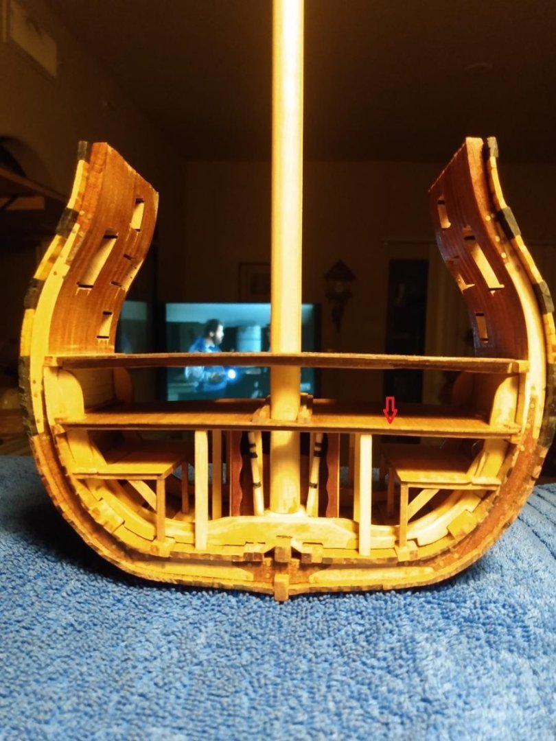
Carpenter's walk. Giving 'human reach' access to the hull so that caulking, plugging or other forms of emergency repair can be done while under way from the interior. Slowing the intake of water reduces the pumping burden, and identifying rot or other problems with durability before collapse reduces the risk of sudden foundering so more or less frequent access for examination was necessary.
- Keith Black, tmj and mtaylor
-
3
-
8 hours ago, mtaylor said:
Basically, anything in casks as it would need to be sealed from water and mold. The first thing in the bottom would be ballast.
That is the hold, rather than the Orlop - the deck situated just below the waterline, below the lower gun deck, but clear of the hold.
- Keith Black, mtaylor and tmj
-
3
-
3 hours ago, thibaultron said:
I've been drawing up the Armstrongs and Fredericks. Drawings and photos show them without the rings. The Blomefields I'm working on now do have the rings.
I think he means the astragal of the button, not a breeching ring, which is what I take from your comment.
The A-F gun has a ring around the 'equator' of the button - an astragal with no listel, but otherwise similar to the astragals of the vent and chase.- mtaylor, thibaultron and Keith Black
-
3
-
72 OA doesn't sound right. Gun lengths tended to be in 6" lengths, from breech ring to muzzle face, and the cascabel and breech 2 calibres or a little over 7.3" - (roughly) 71.3" is a possible overall length from a 66" gun, but 72 doesn't fit the scheme. ... but the standard naval patterns for 6pdr only start from 6ft (72") and run up to 8.5ft (earlier to even longer guns including at least the 9ft pattern).
I doubt that the ordnance was any shorter than 72" from breechring to muzzle face, or was improperly referred to by the other measure using an incorrect value. -
For 3d printing at a not too large size (and with some ability to scale to suit) you could look at the sailor/gunner/rower crew sets by Alf Scherer might be useful. His stuff can be found over at MyMiniFactory - and while I haven't used any of his figures myself (FDM printer and smallish figures are not a fantastic match - Resin printers should do much better though). I have printed a number of his other models.
Detail seems to be at around the level of older 1/72 scale plastic figures, but you can print/have printed as many as you need.
Rowers/crew for a bireme and viking ships as well as C17th and C18th/19th age of sail peeps should give a fair bit of utility if they are suitable and the sets are inexpensive for a 'suck it and see' if you have a suitable printer (or a friend with one and the willingness to indulge).- mtaylor and Keith Black
-
2
-
On 5/25/2023 at 11:15 PM, uss frolick said:
The French also had an unusual way of rigging their iron 24 and 36 pounder carronades after about 1805. The breach rope was one continuous loop that ran outside the hull through special scuppers and sat in a lead trough that ran below the outside bottom of the port cill. Odd. It must have evened-out the recoil when the carronade was trained at an angle, but it made the breach rope vulnerable to enemy fire. The US Navy carronades of the period were double breached for extra security. But one of the breaches ran through the hull in lead scuppers and ended in a knot or a fid, while the other was secured on the inside to a ringbolt in a British fashion. I'm not sure which was the main breach, and which was the backup, or preventer breach.
That was a caronade rigged on the non-recoiling principle - the breeching absorbed the recoil energy 'in place' with only 'slack' in the carriage assisting.
The first arrangement of their obusiers and very early caronades were mounted similarly to British Carronades with a long slide and a breeching that brought up the upper slide in the recoiled position.
I think the date of conversion to non-recoil was a little later than 1805 - Martin (1828) says copying British practice starting in 1806, with the definitive order for the arrangement in 1811.- thibaultron, mtaylor and Canute
-
3
-
What is quite frustrating is that most of the ships at Trafalgar are given the 'raw' 1770s establishment of guns in most books about the battle, despite a 1794 general issue of carronades as supernumerary weapons, and a few examples being quoted of the replacement of establishment guns by additional carronades on the QD and/or FC, the formula 'QD and FC armament variously augmented or replaced by carronades in service' being particularly unhelpful.
We know this was done on a per ship basis, and to a degree at the discretion of the captain (especially as it relates to roundhouse carronades before the (near) complete replacement of QD guns by carronades and the deletion of roundhouse armament from the establishments, but there has to be better and more data than the obsolete establishment of guns from before the advent of carronades, and a notation that carronades were sometimes added in various numbers and sizes...)
Of course an AO authorising Carronades doesn't actually cast the numbers required... so there is going to be a delay between the new orders and the fitting of the last vessel to that standard, but it would be nice to have a better representation of the progression of changes and the actual and/or likely armament at the major actions, rather than a known 'probably not' fit of guns only. -
That 1860s US naval gun is a copy of part of a figure engraved in "Ordnance instructions for the United States navy."
Unsure who copied the diagram by hand, or when, but that book is available online in various places including the Library of Congress.
- Keith Black, thibaultron and mtaylor
-
3
-
I'd also note that the plan view of the carriage in Plan X is clearly seen as being in the plane GH, which is why the bolt-head and the forward train tackle ring are superimposed. The train tackle bolt is somewhat rear-ward of the bed support through bolt when the fore and rear axle trees are fitted relative to the centre of the axles, and to the trucks when they are fitted too (As seen in the side profile with a horizontal 'floor'). In situ some of this is again taken out, as the additional height below the foot of the cheek at the fore end is at least partially to compensate for the deck camber in battery.
- Gregory, mtaylor and thibaultron
-
3
-
1 hour ago, Gregory said:
Did gun crews dress like that? I'm thinking some noble/aristocrat had himself painted as part of a gun crew..
The uniform of the marine/soldat assisting would be similar to that of a regular artillery soldier in the land service - which could get quite 'fancy'. The remaining crew would also have a uniform similar to that shown, though the 'officer' does appear to be one of the Maitres, Lt or Ensigns supervising the division, rather than a common member of the crew.
As for the recoil - even without breeching the gun will roll back (and 'up' on the camber of the deck), and will be halted by friction of the trucks and running of the tackle falls - with light artillery this will be at or inside the limit of the breeching, but with heavier guns (as this appears to be an 18 livre canon) the recoil will be longer than the normal limit... however, this also appearing to be a French style carriage is breeched at the cheeks, rather than the bouton. It would probably have a preventer rigged to the gun, but the main breeching would be passed through the carriage cheeks.
While a heavy uniform might be hot to work in, there is considerable flash and risk of splinters from penetrations, and while nothing will help against the larger ones torn from knees and waterways, the smaller splinters torn from the thinner quick-work by the passage of high velocity shot are largely stopped by woollen uniforms. The portrayal of fighting stripped to the waist seems imprudent in the context of a naval engagement, though might be seen in embarcation actions, where there is a risk of sinking and no elevated risk of splinters once ashore.
While not in itself a 'proof' the gallery at "Artillery through the ages" of a living history group displays the types of uniform authorised for RN sailors in the gun crew.- DaveBaxt, bruce d, thibaultron and 3 others
-
6
-
Unsure on the double tackle rings, but a plausible use would be for the wider angles of train required from later ships to suit the change to individual close action following enveloping of the enemy rear, rather than fighting in line ahead against a more distant enemy.
The train tackle can be set to use the forward ring on the side the gun is trained to, and the rear ring on the side being drawn toward the bulwark to reduce the difference in the length of the tackle required to haul and to help control the recoil (before the residual is taken up with the breeching and preventer).
Calculations indicate that some of the smaller bore ordnance of the longer patterns could be brought to a halt by the friction of the trucks and the paying out of the tackle falls by a distance shorter than the length of the gun, while the relatively lighter large bore guns would still carry some velocity through the recoil distance before being brought up.- DaveBaxt, mtaylor and thibaultron
-
3
-
In the side view, the two small circles (one in the transom, one in the clear behind the breeching ring ring bolt) are the heads of the through bolts. The two smaller rings (seen as the smaller rectangles) and the breeching ring ring bolt don't have a through rod, and are bolted from the inside of the cheek, like how the cheek pieces are held together with a bolt. The square nut is in a pocket, with the loop being screwed into it, rather than the bolt head in a pocket with the nut tightened onto the bolt in the vertical rods, but the principle is similar.
- thibaultron, bruce d and mtaylor
-
2
-
 1
1
-
There is a through bolt with external bolt heads at the height of the breeching ring ring bolts. The smaller pairs of rings and the breeching ring ring bolts are bolted in each cheek, but don't cross the interval between them.
- thibaultron, DaveBaxt and mtaylor
-
3
-
Those two stern chase ports (at least) should be unfilled, or use the guns from the aftmost broadside QD port. Guns would not be supplied to both in general, especially when so cramped - both couldn't recoil without contact and/or serious risk to guns crew.
I also question the number of QD/FC ordnance in general - my notes indicate only 10 6pdrs as built (all on QD?), 16 24pdr carronades as refitted following her first cruise, and 20 total once refitted in 1810 with her final 32pdr carronade establishment (though 4 of them are then the 12pdr guns, with another 2 of these also on the upper deck (main battery deck)) -
39 minutes ago, Benjamin sullivan said:
I am sorry but I am confused. so correct me if i'm wrong but pdr means the weight of the projectetil that is being shot right ?
Yes, but if you have two patterns of ordnance, both 8.5ft long - then a 24pdr will look short and squat if compared to a rather narrower and more elegant 6pdr would. The proportions of a shorter gun in each bore look more like the heavier guns than to the longest pattern of the smaller size. If you are scaling from an existing 3d model (though you indicate you may not be doing this), then scaling a heavier pattern to a smaller size might give a better result than using a too-long gun of the correct bore.
The 12pdr short US pattern of the 1790s is rather closer to the proportion of a 32pdr Armstrong than a 12pdr Armstrong (iron, naval) of any pattern actually built would be, once reduced in proportion of 4.623:6.41(the bore of the 12pdr:32pdr)


32 Pounder Blomefield George 3rd Cannon 3D printable STL. Full Size File thibaultron
in CAD and 3D Modelling/Drafting Plans with Software
Posted
7.5ft and 9ft (breech ring to muzzle face) 12pdrs and a 9.5ft 24pdr (overall length is roughly 2 calibres longer with the cascable and button).
The full suite of guns includes these common lengths...
32pdr 9.5ft
24pdr 9.5ft, 9ft
18pdr 9ft, 8ft
12pdr 9ft, 8.5ft, 7.5ft (land service iron (no breeching ring) 6ft)
9pdr 9ft, 8.5ft, 7.5ft, 7ft (land service iron 5.5ft)
6pdr 7ft, 6.5ft, 6ft (there are other theoretical lengths mostly longer, but the 6pdr was mostly deprecated by now)
The group of rebored guns include other lengths of these patterns which I've only ever seen as donors for rebore natures... as well as some more common types, but that is deep into the 1820s, 1830s and beyond. They externally look identical to the original pattern of smaller gun, but with a larger diameter bore to suit their new purpose.