HOLIDAY DONATION DRIVE - SUPPORT MSW - DO YOUR PART TO KEEP THIS GREAT FORUM GOING! (Only 36 donations so far out of 49,000 members - C'mon guys!)
×


rfolsom
-
Posts
881 -
Joined
-
Last visited
Content Type
Profiles
Forums
Gallery
Events
Everything posted by rfolsom
-
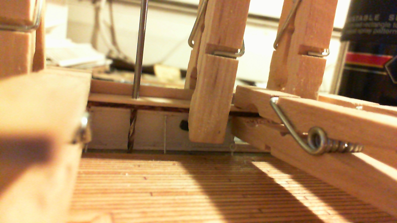
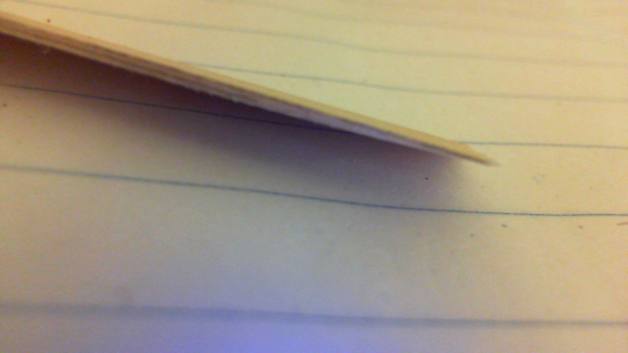
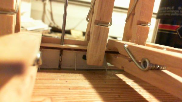
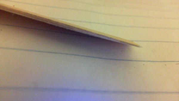
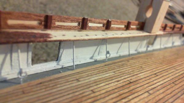
 I think the repair should work reasonably well. I shaped the shim, feathered the ends, and drilled the remaining holes. I was afraid the thicker rail would screw up the belaying pin seating, but test fits look ok. The picture of the feathering at the fore of the repair shows how the thin glue layer is lifting up after the sanding; the stain will probably not take in this thin area, but after all this it's something I can live with....
 -
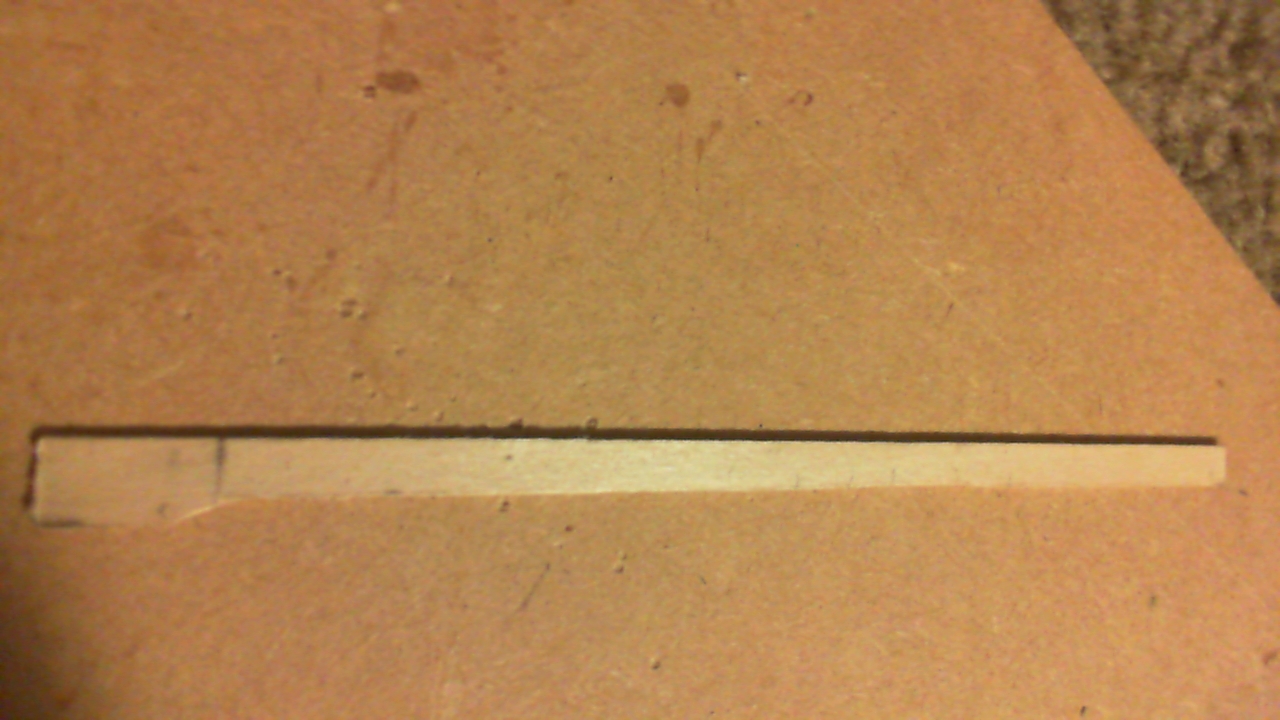
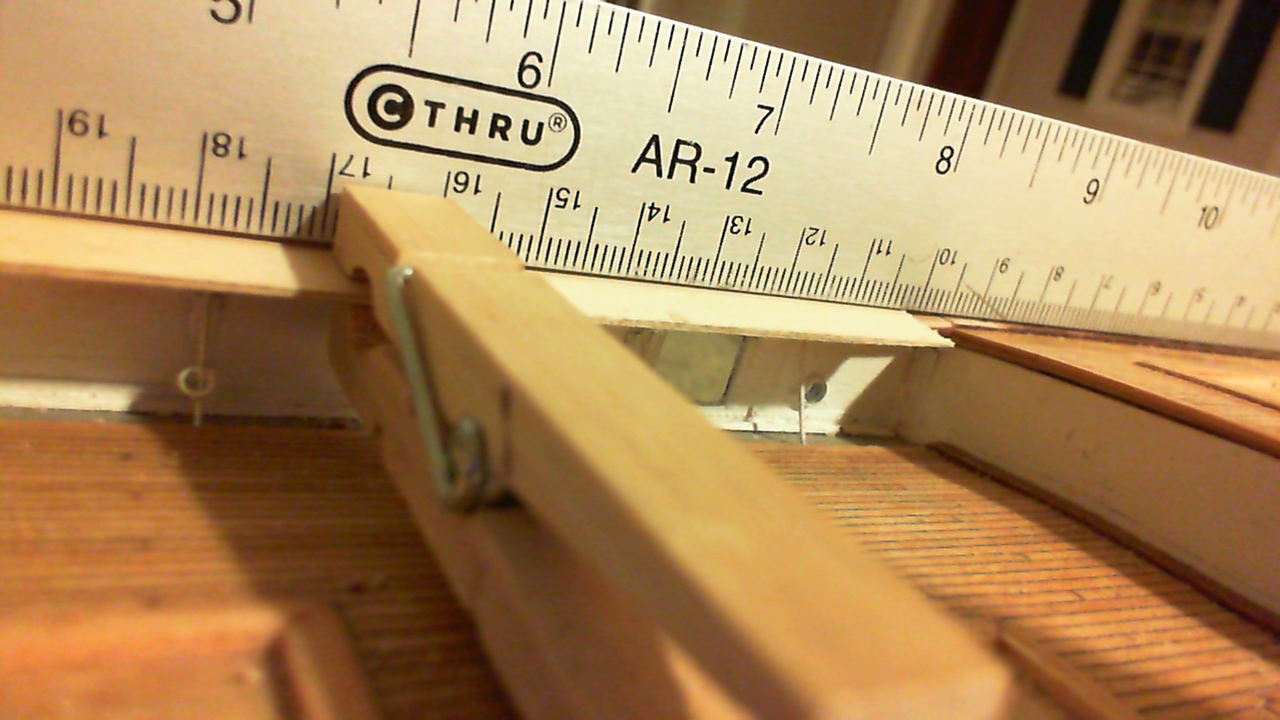
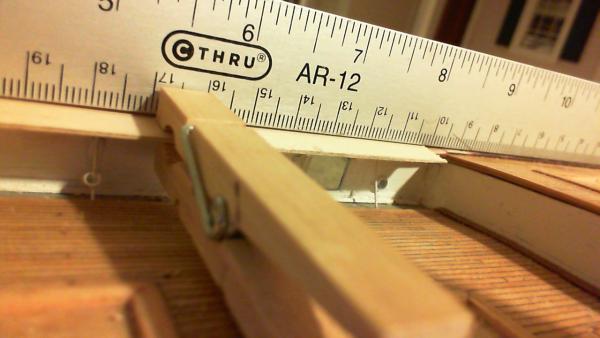
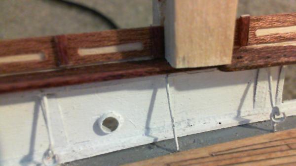
This rail section will be quite thick, but hopefully will not be too noticeable after shaping and staining. Should look much better than trying to dip everything else to follow the erroneous curve. The drill bit is in a davit hole for alignment purposes.
-
Two davit holes, one deadeye hole, and three belaying holes will have to be re-drilled in this 13 cm long area; I pre-drilled the davit holes to help in aligning the repair piece. Here is the offending section drying:
-
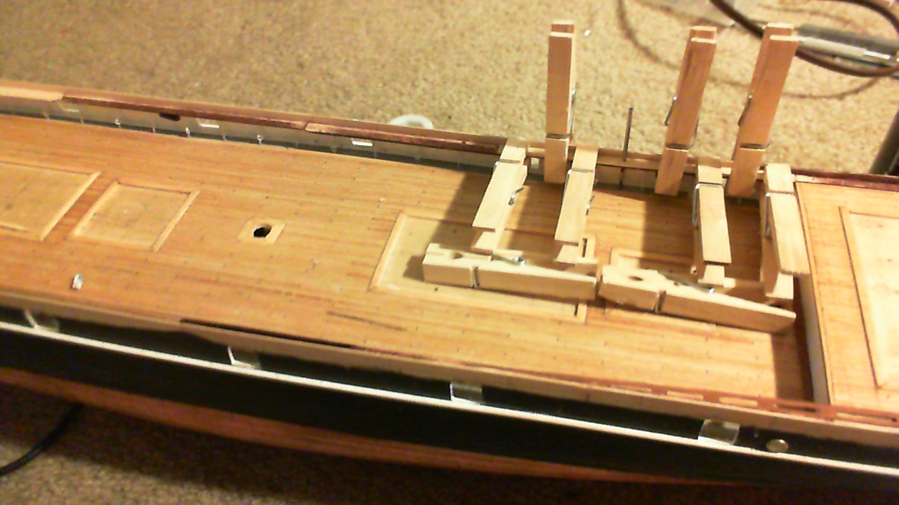
Ha, ha; Nenad; You're right! I've been in denial all this time... Repairs have begun: Tapered piece is shaped to overlap the dipping rail section:

-
Thanks, Keith and Nenad; It's not fixed yet, just a rough piece test fitted. We'll see tomorrow if it works. After tomorrow, I have two days off of work; hope to get these white panels (embellishment strips) installed... Cathead prototyping is also a challenge because of so many conflicting points of view. Even Campbell's plans don't agree completely from port to starboard! I plan to install catheads before I mount my topgallent rail. Once the topgallent rail is installed, I feel many variables will be resolved finally, as the hull will be mostly complete.. I can then move on to the outside detailing (freeing port covers, rudder, rubbing strakes, etc. or the deckhouses, spars, pumps ( I have no idea...) Sometime during all this I'll have to learn actual metalwork fabrication (not aluminum cans cut out with scissors and glued with cyano) and make a modest to substantial investment in tools, materials, time, and experimentation. Fun hobby, or insanity?... A little bit of both, I think. That's what gives it the extra fun!
-
So, pondering my options: 1) Ignore it. Bend the embellishment strips to follow the curve; (Then bend the topgallant rail, etc. etc.) 2) Fix it. Tear out the whole area, probably destroying 14 + cm of bulwarks, stanchions, riveting detail, rails, etc. etc. I don't think so... Bingo! 3) Hide it! I will take a 1/32" strip of basswood, feather both ends, and laminate it to the dipping portion of the existing rail, feathering it into place and re-drilling holes... This will ultimately give me a thicker rail in this area, but after some shaping, the thickness should be hidden mostly underneath the rail itself... I'll let you know how it goes, but I think this is enough excitement for me this evening.
-
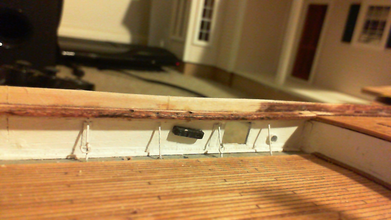
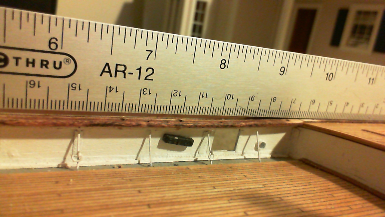
Ok, going back to the endless fitting of the inside bulwark embellishment strip... Yikes! Big error! The main rail on the starboard aft side, between the main and mizzen areas, dips WAY down before going back up to meet the rail at the poop deck. This error would originally have been made when I affixed the hidden "stanchion rails"; as the main rail follows this rail. (You can even see my exposed pencil mark... how did I not catch this 6 weeks ago?? Can't see the forest through the trees...)


-
Cutty Sark by NenadM
rfolsom replied to NenadM's topic in - Build logs for subjects built 1851 - 1900
Not sure what you mean by "lawns", but coppering is looking good! ~Bob -
Very useful, indeed, Nenad; I didn't have a picture that shows the tumbler and the end of the whisker boom. Thank you! Bob
-
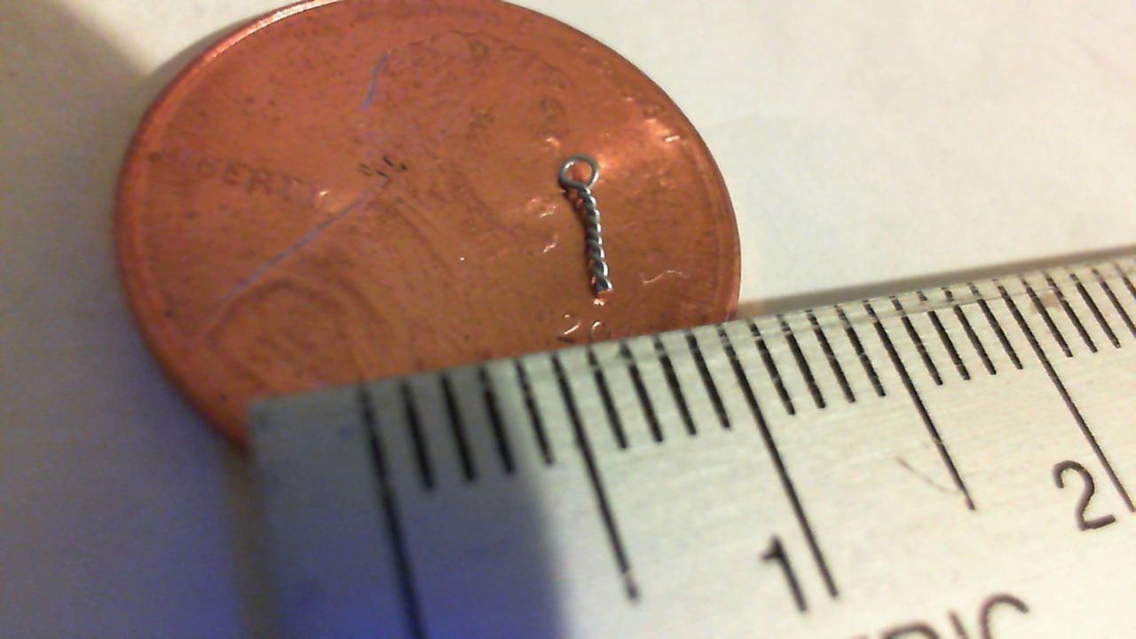
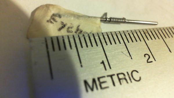
Thanks for all the nice words of encouragement, my friends; Most all of the eyebolts on this ship will be scratch built; one of the things that nagged me about my Revell Cutty that I assembled at age 14 or 16 was the cumbersome, out of scale plastic eyebolts; most either melted with the plastic cement, or broke when rigging. (I didn't know about scratch building at that time) So even before I laid the keel of this build, I practiced making eyebolts from twisting 30 gauge wire around a broken 0.8 mm drill bit. Continuing with my cathead testing, I surrounded the distal end with an "iron" (aluminum can) band with an eyebolt for the fore tack block.... (Still haven't figured out the sheaves yet.)


-
I like your success with the rope caulking; I tried a test when I initially started my planking, but couldn't get the rope to behave... The deck area where the bowsprit mounts will also be covered with the forecastle deck, so no worries there... Keep up the good work; Nice to see another ancient Billings' Cutty coming along. ~Bob
-
Cutty Sark by NenadM
rfolsom replied to NenadM's topic in - Build logs for subjects built 1851 - 1900
Nice index; I clicked on one of your links, and found your post that I read about 2 years ago. My, we're getting old very quickly.. Oh, and congrats to Princess! ~Bob- 4,152 replies
-
- 1
-

-
- cutty sark
- tehnodidakta
- (and 1 more)
-
Thanks, Nenad; I will be fiddling with these "strips" for awhile before affixing them. The first strip in the port bow area, has fifteen panels. I think I'm satisfied with one out of the fifteen. I believe I posted tests earlier with the mooring pipes; they should be oval, but I gave up an am using brass airports from ModelExpo. I tried using a ring; but after putting it into the bulwarks, it looks ok.
-
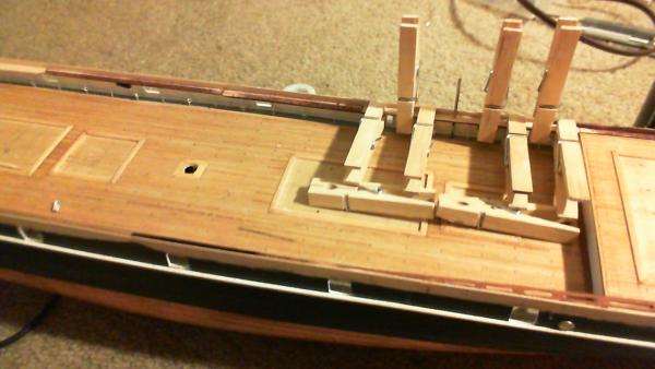
... So here's where I'm at; test fitting these bulwark "augmentation strips" , trying to get the ovals actually "oval" .. Main rail needs final sanding and staining; The whole deck needs cleaning and touching up; the debris is quite evident in these photos. Not alot of noticeable change, but at least I'm working on the build faithfully again... ~Bob
-
Cutty Sark by NenadM
rfolsom replied to NenadM's topic in - Build logs for subjects built 1851 - 1900
Outstanding work, my friend..- 4,152 replies
-
- 1
-
-
- cutty sark
- tehnodidakta
- (and 1 more)
-
Keith; I had thought of that option, but the fragility of the assembly would make it next to impossible. A 4 mm drill bit would destroy the sheave slots.
-
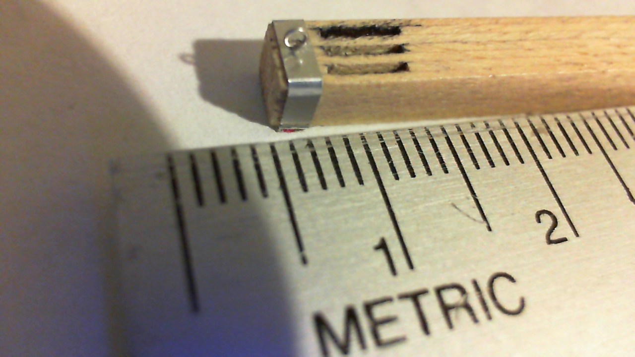
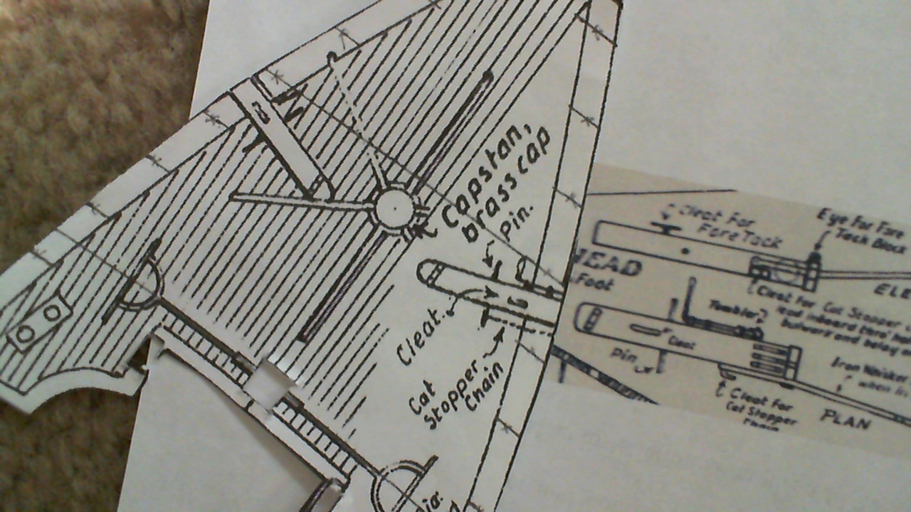
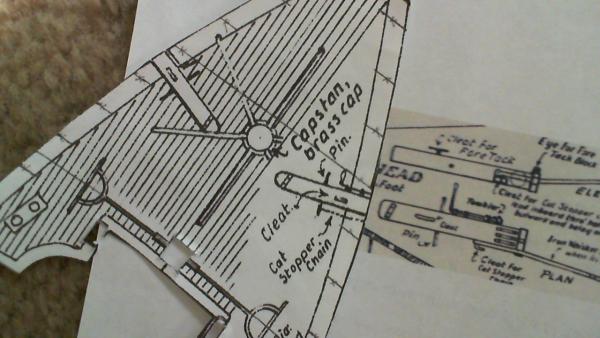
Nenad; Fair warning ahead of time on the catheads; Mr. C's plans Do Not agree in this area! His enlarged details on the cats just to the right of your above posted area on the plans will not match up with each other... This is the biggest (and only) discrepancy I've found yet with Campbell's plans. These copies are from the same plan sheet. On the left, 3/32" = 1' enlarged by 166.667% for my scale; On the right, 1/8" = 1' enlarged by 125.000% to also match my scale. Notice how they are much narrower on my plan cutout on the left... their length (without whisker booms) is 38 mm on the left plans, and 36 mm on the right plans. (narrower and longer, vs. wider and shorter... obviously not a scaling issue) and I double, triple, and quadruple checked my plan scaling...
-
Ha! Keith, You sparked some good old memories for me... My father was a model railroader who had a lathe many years before I was born... In high school, when I did plastic models, I did the Pocher Mercedes, with about 150 parts for each wheel. I was lazy back then, and paid Dad (retired) $5 to file out the metal rings for the wheels, which he happily did. So I was just wishing Dad was here to make these things... Brother-in-law has the lathe; but I don't have the room for it yet..
-
Thanks for looking in Kevin; I haven't checked your log for awhile because I get too distracted as it is with my two builds, and I think: (hmmm. Bismark; can I squeeze this in..?) Maybe if I live to be 180 yrs. Bob
-
Yes, Nenad; You do like to torture.... But that's how real problem solving works! (We all know this!....)
-
Cutty Sark by NenadM
rfolsom replied to NenadM's topic in - Build logs for subjects built 1851 - 1900
Nenad; It's good to see your research and testing paid off; as I think I mentioned much earlier, 90% is researching, thinking, planning, measuring, testing, failing, testing again... and of course the "hmmmm....." before the final 10% of... Success! and progress! (how long does it take you to affix 200, 200+ plates; I only cut about 30-50 at one time...) Also, is your material available in the US? When I coppered, I noticed an errant fingernail would leave a nasty dent if not handled right. As I posted on my log, we all will get to the point where inverting the hull will be impossible; I will then invert my hull, check out the copper, and replace where necessary. I really like the way the natural copper ages, so I won't be coating it with anything. That is when She'll be permanently mounted to Her mounting board.- 4,152 replies
-
- 2
-
-
- cutty sark
- tehnodidakta
- (and 1 more)
-
Cutty Sark by NenadM
rfolsom replied to NenadM's topic in - Build logs for subjects built 1851 - 1900
Nice mass production on the tiles; I was forced to do each one individually, but my copper tape was the right width so cutting was easy... Great progress! ~Bob -
Thanks for the input, gentlemen; I would really like to incorporate actual round sheaves in this model; however, it's going to be a long search unless a supplier makes them, or I get some divine inspiration
-
Hello, Nenad; good to hear from you... I've been thinking about the "add" (sheave) but their fabrication is beyond my means; (I've tried!) However, I could possibly simulate this by drilling a hole through the whole assembly and inserting a 1/8" dowel; but I have a feeling it would disintegrate the structure... I may also try finding a punch for aluminum that might get me there... We shall see...
-
I'll be using sanding sealer on the outside to smooth out the "bumpiness" of the sapeli wood before painting. Unless I can find pre-fabricated 1/8" metal disks to use as the sheaves, the sheave slots will probably remain blank...