HOLIDAY DONATION DRIVE - SUPPORT MSW - DO YOUR PART TO KEEP THIS GREAT FORUM GOING! (Only 36 donations so far out of 49,000 members - C'mon guys!)
×


rfolsom
-
Posts
881 -
Joined
-
Last visited
Content Type
Profiles
Forums
Gallery
Events
Everything posted by rfolsom
-

Cutty Sark by Keith B
rfolsom replied to Keith B's topic in - Build logs for subjects built 1851 - 1900
Superb work, Keith; and as Nenad said, very fast! Did you use eyelets for your hatch covers? I like the look.... ~Bob -
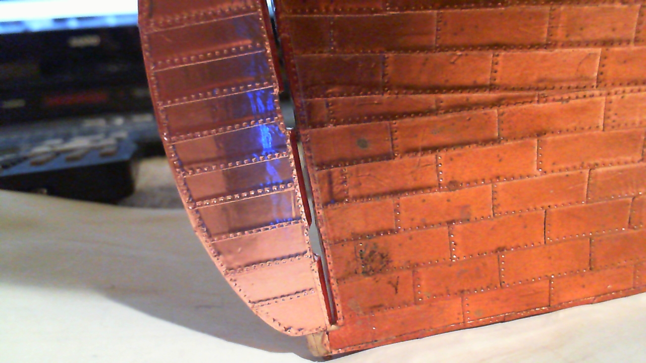
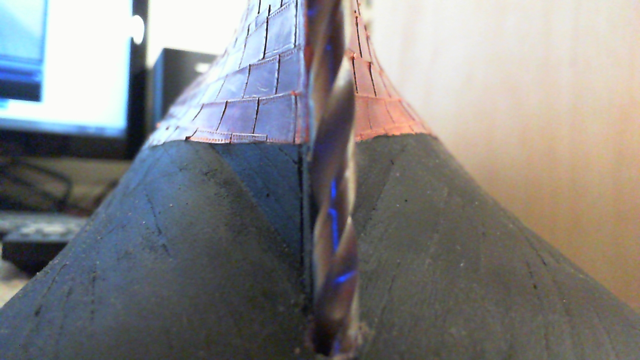
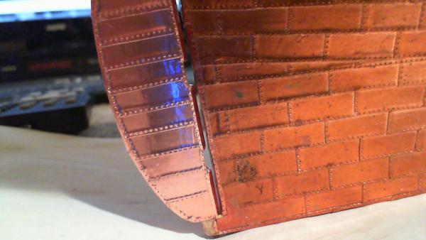
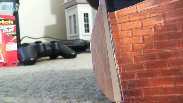
Thanks, Redbeard; pull up a chair! My friend Nenad always keeps things interesting... After coppering the rudder, I knew there would be a "patina mismatch" with the hull. The rudder almost looks pink from a distance.... I'm going to say that the rudder was lost in heavy seas, and replaced with a new one... (That's my story, and I'm sticking with it ) Seriously; It will probably take another 2 to 3 years to complete the ship, at which time the oxidized copper on the rudder and the hull should match. (This copper tape was all from the same roll, BTW.)

-
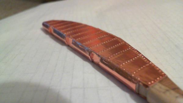
Rudder is now coppered...

-
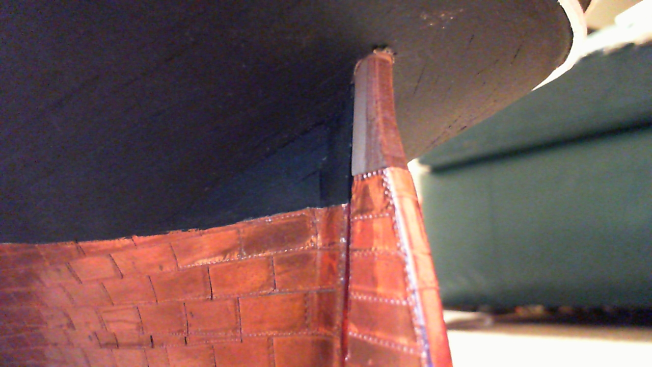
Coppered inner surfaces of notches...

-
Fashioned a few more gudgeons and cut notches into the rudder; also coppered the trailing edge...

-
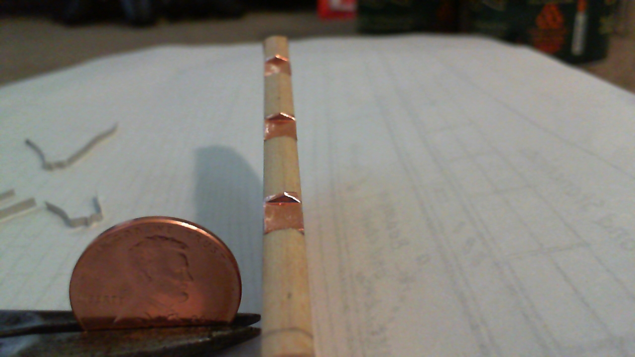
Moving along... I like the way the gudgeons are turning out, and forming them over the small nails that I will use as pintles is working out well. This is mainly Nenad's technique, but I won't be soldering anything. I will probably use CA; but I'll be test fitting before a final decision is made. I will now find out where the rudder notches will be finally located; after they are cut, I can start the rudder coppering. I am very much not superstitious, but now I have the look at the back of my AL strips....
-
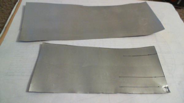
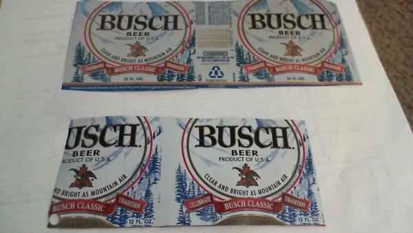
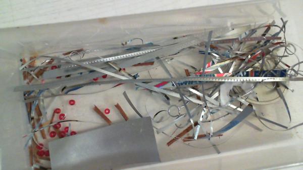
Ok, small side note to convince everyone (and myself) that I'm not losing my mind... I cut apart three or four aluminum cans several months back, flattened them out, and squared them up roughly. I have a little bin with many different sized AL strips cut from these sheets, some with rivet detail, some without. I just happened to pick out one with legible printing on the obverse side...
-
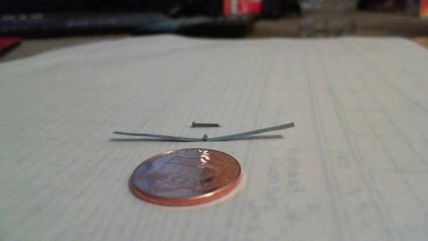
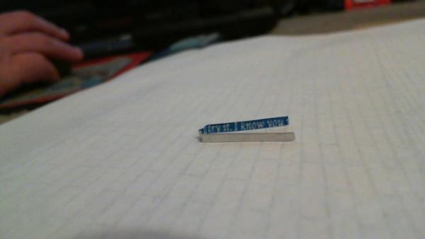
Well now, this is weird.. I fashioned a test gudgeon from AL can (I think I washed and cut out three cans back when I was making rivet strips, and have a ton of material left to work with..) I fiddled with it off and on, on both the rudder and sternpost, ignoring the inside with the painted beer can markings.. But when I went to photo it up close, the inside read "..try it. I know you.." I swear I did not do this on purpose; but what are the chances?!
-
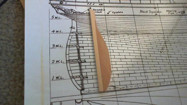
Alright; I've shaped the fairing piece outline on the rudder; next will be determining where to place the notches. They are bigger than needed in order to provide clearance when removing the rudder for repairs. Also testing out gudgeons with aluminum can pieces...
-
Cutty Sark by NenadM
rfolsom replied to NenadM's topic in - Build logs for subjects built 1851 - 1900
Looks great, Nenad! That's my next major milestone (getting the outside hull "finished" and ready for scrollwork and head timbers)....- 4,152 replies
-
- 1
-

-
- cutty sark
- tehnodidakta
- (and 1 more)
-
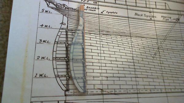
Thanks for the kind words, Keith; glad to hear someone else using his T and F drill... Nenad; thanks for the detailed photo; page 153 of Campell's China Tea Clippers shows very detailed drawings of rudders, including the fairing pieces (triangular pieces running the length of the rudder and sternpost where they meet. It is too late to duplicate this on the sternpost, but I'll probably file the triangular surface onto the rudder, and notch accordingly. This picture shows the rudder in place, temporarily held by a small removable nail at the bottom. I'm not sure what material I'll be fashioning the hinges from, probably AL can, but I won't be able to solder. (I don't have the equipment yet to solder structurally, anyhow.) The rudder sits very solidly without any glue, just held by the rudder stock and small nail, so the hinges will not need to bear any loads.
-
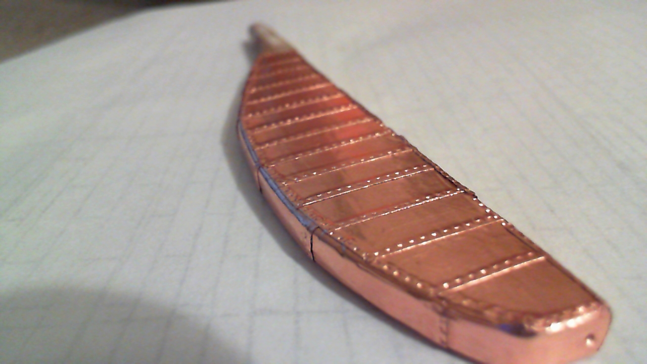
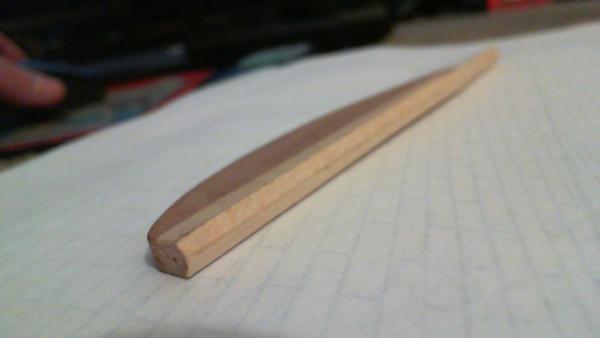
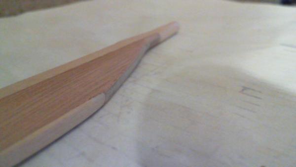
Rudder is shaped; I'll dry-fit it into place before doing any detailing (coppering, painting, pintles and gudgeons, etc.) And still drilling with the T and F drill...
-
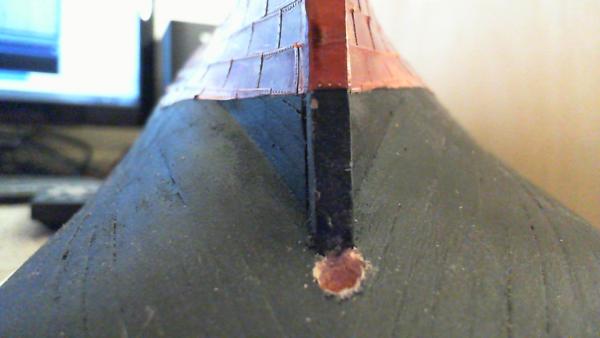
About twenty minutes later, I drilled about 1/8" deeper than the planking and into the center keel. With sore fingers, I'll try some more later....
-
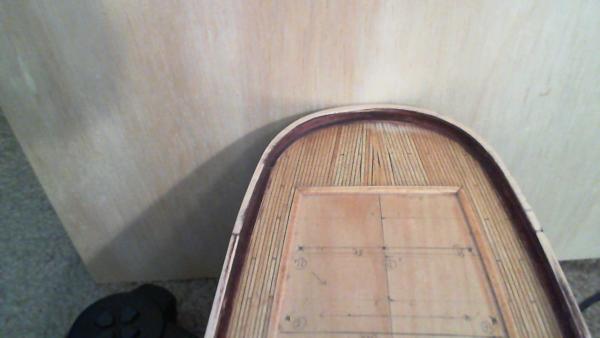
Had to invert the hull to drill a 3/16" hole for the rudder stock. I used my trusty "T and F" drill... (thumb and forefinger; I was not about to use a power tool for this, and my pin vise is only a little larger than the bit itself..)

-
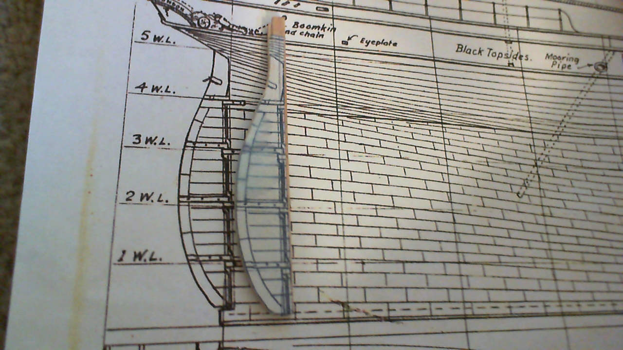
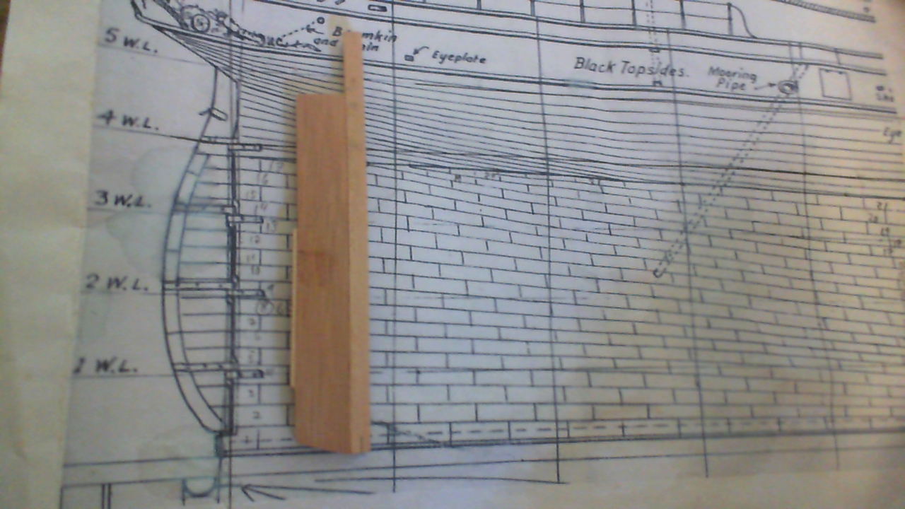
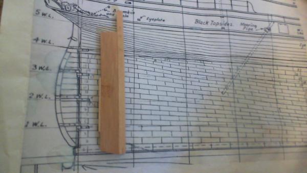
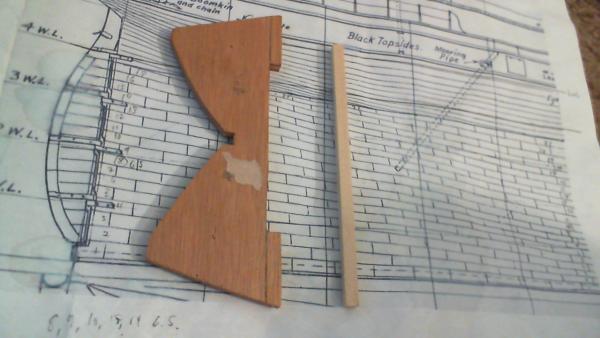
Blank with template, rough cut..
-
Rudder blank..
-
Well, I was going to use the kit-supplied die-cut plywood rudder, but It seems to be missing now. I rather like the 40+ year old plywood from this Billings kit, as it is more dense than the plywood I have on hand, so I will be making the rudder stock from 3/16" square basswood (easier to shape rounded at the top), and the rudder blade from a piece of the original plywood meant for the stand.
-
Thanks, Nenad. I am satisfied. Things could have been done better, (but they always could be done better; ad infinitum..) I think it's time for the rudder, now that I'm comfortable inverting the hull once again. I'll also be checking out the copper plating, and touching up any damage I don't like. As far as little sailors go, only the runaway Piggy pokes his head out from time to time...
-
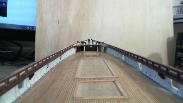
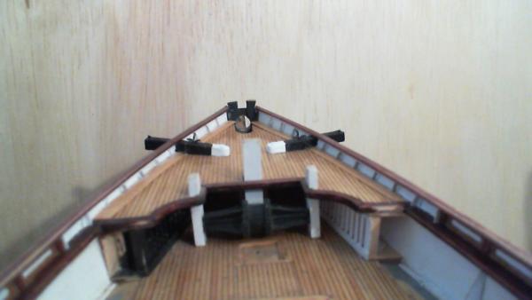
Ok. All topgallant railing is now installed, and sanding is almost complete. Final staining will follow shortly. This is a major milestone for me, as the bulwarks are now structurally complete, and everything is tied together. It was amazing to see how these 1/32" basswood bulwarks got progressively stronger as the stanchions, panel strips, and railings were installed.
-
Thanks, Popeye. I'm still not satisfied with the white paint job on the ends; we'll see if I get the nerve to repaint or leave as-is.
-
Cutty Sark by NenadM
rfolsom replied to NenadM's topic in - Build logs for subjects built 1851 - 1900
Aha! looks like I'm your first post on page 100 of your log!- 4,152 replies
-
- 4
-
-
- cutty sark
- tehnodidakta
- (and 1 more)
-
Cutty Sark by NenadM
rfolsom replied to NenadM's topic in - Build logs for subjects built 1851 - 1900
Great work! Looking forward to seeing the finished rudder circle.. -
Cutty Sark by Keith B
rfolsom replied to Keith B's topic in - Build logs for subjects built 1851 - 1900
Looking great! are the stanchions part of the AL plans, or your own addition? ~Bob -
Cutty Sark by Keith B
rfolsom replied to Keith B's topic in - Build logs for subjects built 1851 - 1900
Wow, great progress! I hope the ship in the bin is not haunting you.... -
Thanks Nenad. This is why I view the finishing of the topgallant rails a major milestone; as they are a prominant feature of the entire hull. If I can get this area down, I might now be able to progress...