
HOLIDAY DONATION DRIVE - SUPPORT MSW - DO YOUR PART TO KEEP THIS GREAT FORUM GOING! (Only 13 donations so far - C'mon guys!)
×


Avi
-
Posts
323 -
Joined
-
Last visited
Content Type
Profiles
Forums
Gallery
Events
Everything posted by Avi
-
Very impressive
-
It is CA; you could sand it down and paint it @Canute 🙂
-
As an interesting side note, I cut my finger on the tip last, no stitches, stopped bleeding reasonably quickly. But afterwards there was a small flap that, when knocked/pushed, hurt as it flipped back. I didn't want a bandage - gets in the way of life and work - so I put on a dab of thin CA, waited for it to set, went about my day. Repeated every day for 2-3 days, no problems. It isn't just for the model ships! 🙂 I probably will order the Bob Smith. Thoughts on Starbond?
-
@DelF is the regular version problematic with odour? I just found two online stores here in Israel that carry it as well, so I should be good.
-
You know, @ERS Rich, I didn’t check the sharpness, but you’re probably right. All of the tools are new and could use a sharpening. The mini plane is a fabulous idea. I could chisel or gouge all of the way from bow to stern, but that would be slow and painful, and need a lot more sanding. thanks for the great ideas and help!
-
How did you know that the purple “instacure+” is the medium? I guess the blue is the thin and the red thick?
-
They appear to have so many variants on Amazon - super thin, thin, gap filling, instacure, etc. do you mind sharing a link to the medium you get?
-
What brand do you use @glbarlow? I’m about to get some (hull planking is coming up soon), would really be interested in what you recommend. I’ve also found getting consistencies on the major brands (Crazy, Gorilla, etc) a bit of a headache, as they don’t (seem to) list the consistencies, just interesting marketing names, like “gel” or “original”. That doesn’t help if I just want some medium, some thick for filling, etc thanks!
-
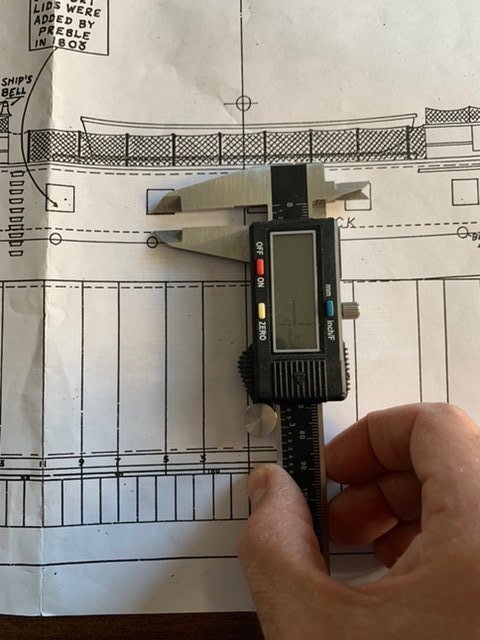
No pictures today. Took about 5 mins with that gauge to get a nice ⅛" all the way around. Based on the excellent build log by @ERS Rich, notably these pictures, as well as actual pictures from the ship in Boston, the caprail at the bows is about the same thickness as around the rest of the ship. The rest of the "walls" - bulwarks, gunwale, etc. - at the bows are TBD, but appear to be roughly similar to the rest: either consistent thickness, or thickening some as it goes down, especially below the spardeck. I used a combination of chisels and gouges to dig off much of the material around the sides. Unfortunately, these are rather crude tools, so I am left with a lot of material. I have been sanding it down slowly but surely, combination of a sanding block (I really like this one), sanding contours, and files. I have been tempted to use a power hand sander, but really worry about doing something very difficult to fix. The port and starboard sides are getting there, slowly, from forward to aft. The bows will be difficult due to: the sheer thickness of the material left there from the original hull as shipped by BlueJacket, the port to starboard curve, and the inward curve as you go down from the caprail. I will tackle that part last.
-
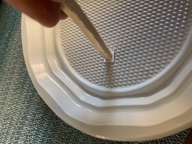
Finally got my marking gauge, after being away on vacation for a while, so back on the game. I set it to ⅛”, and away it marks. I need to figure out how thick to make the bulwarks at the bows. The port and starboard side are fine at that thickness, still figuring out the bows.
-
Wow @ERS Rich that spardeck is beautiful!
-
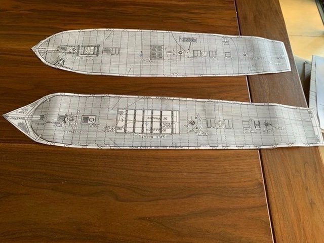
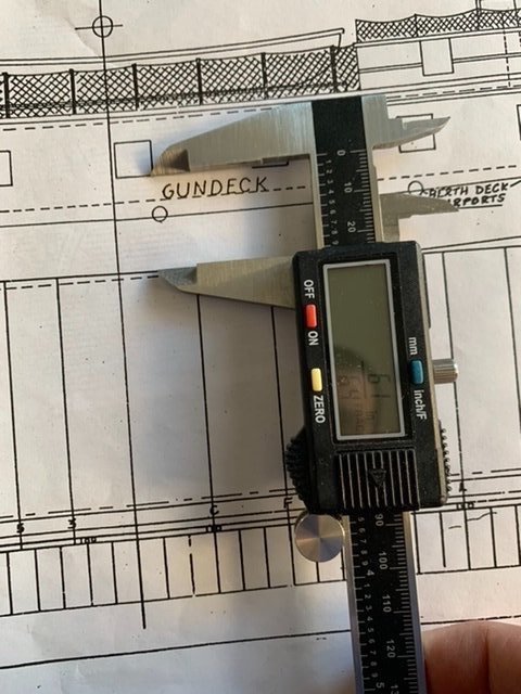
While I await a marking gauge so I can get the bulwarks the right width, I decided to tackle marking the gun ports, starting with the gundeck. I definitely do not want to cut them out before finishing the bulwarks. It is much easier to shape them and send them when they are a single surface than when they are interrupted by holes (the ports) every ½" or so. In theory, the gunports should be easy: they are all the same sizes (3/8" x 3/8") and are the exact same height above the gundeck at ¼". In practice, it isn't quite that easy, since the gundeck itself curves upwards as you go from amidships to the bow or stern. If I had the gundeck marked precisely on the outside of the hull, then it would be easier, but that just defers the problem of getting the gundeck marked properly. I may yet do that, but the technique and effort for marking the gundeck is the same as the gunports, so might as well do it once. I did the following: Took an extra copy of the blueprints and cut out the spardeck and gundeck plans Laid the gundeck plan on top of the hull, sure to align the (X) midship marking For each gunport, measure from the bottom of the gunport to the waterline, which *is* marked on the outside of the hull Transfer that height to the hull, placing it roughly underneath the location of the gunport in the gundeck plan, which (from before), is sitting on top of the hull. Be extra careful as the waterline is straight, and the ports, while each one is straight, do angle slightly one from the other as you get further from the midship point Made another small copy of part of the hull profile, to get just a few gunports Measure them until I find one that is exactly the desired 3/8" x 3/8". The best one turned out to be just forward of the midship line Cut it out precisely Glue it onto a piece of scrap wood Hold it onto the hull: bottom aligned with the marking from the height-from-waterline measurement, left and right (technically, aft and fore or reversed, depending on sides) aligned with the edges of the gunport in the template on the hull Trace the outline. You have a gunport! Repeat for all of the gunports on the gundeck In practice, I would do one thing differently if I had to do it again (and I may yet): trace the outline from the paper onto something stiffer, like Bristol board. It makes it much easier to trace the outlines.
-
For that part yeah. For the bulwark width, still a little stumped.
-
I sat with the blueprints and a long metal ruler, placed it along the edge of the larboard and matching starboard gunports on the deck plan, and saw where it lined up on the profile. For the spar deck, it was just right. For the gundeck, all were just right except the bridle ports up near the bows, which probably is an artifact of the curvature (or missing) on the profile. I think you may just have gotten unlucky with a bad printing of theirs, Kurt, or they heard your criticisms and fixed it in future printing. That also answers how I will do the gunport locations: with both profile and deck plans matching, I will stick with those over the slightly different Marquardt. In terms of symmetry, I wasn't totally sure what you meant, so I measured at the top (i.e. where the caprail would be) from the very bows of the ship (edge of where the bowsprit will go) to the sternmost part of the bulwarks on both starboard and larboard sides. Both came out to precisely 60cm. which looks fine to my inexperienced eye. Now if only I could figure out carving the interior of the bulwarks.
-
Wow what a build! I love the details. I’m doing a bluejacket Connie right now, so looking at how others are building different models. I love your detailed techniques. she’s coming along beautifully!
-
Thanks for the warning @KHauptfuehrer I am unsure what you mean by “stem to stern on both sides”; isn’t the stem in the middle? also, how did trying to fix it mean you would have sanded through the gunwales?
-
I’m also becoming aware of what @KHauptfuehrer wrote about the gun ports not quite lining up. They’re distinctly different locations in Marquardt vs the blueprints provided with the model. I’m still measuring the locations of them on the profile vs the top down views on the blueprint. in any case, Marquardt vs blueprints? 🤷♂️
-
There is little doubt that I will have to modify. I measured the thickness of the hull (really the bulwarks) at the very top (caprail), and then at the bottom of the gundeck. caprail: 15" thick in reality, scaled at 1:96 is 5/32", which is a little more than ⅛". I have plenty of room to trim down to that. Should be ok. gundeck: 21-22" thick in reality, let's call it 21" (easier to scale) at 1:96 is 7/32". Add the 3/8" (= 12/32") overhang, and it needs to be at least 19/32" thick, or a little more than ½". Even then the remainder - 7.32", or just under ¼", will be quite than (and perhaps brittle). And there's the rub. Other than right amidships - templates C through 17 (depending on the side, maybe a little more towards the bows at L or towards the stern at 23 - there just isn't that much material left. At two spots, it actually is exactly 3/8"! It is possible I shaved down too much (obviously, it didn't seem like it at the time), but that is neither here nor there. I need a solution as to how I am going to continue to get the right shape. One possibility is to have <3/8" overhang, say half of that at 3/16". That would make the minimum thickness required to be 13/32", which I have everywhere (except at the very bows, but they curve forward and thicken that way). A little bit stumped.
-
Thanks @KHauptfuehrer I’ve got Marquadt and will check it out. I’ll also see if I can find some MS builds here
-
Next step: shaping the bulwarks. Unfortunately, the instructions are *really* weak on this, lots of confusion. One piece that stands out to me is that it says the bulwarks are 21” to 22” thick, thinning down to 15” at the caprail. This is the key shaping directive, but the rate of narrowing and where it starts is unclear. Is it 21-22” thick at the foot of the gundeck and thins evenly to 15” at the caprail? Does it stay 21-22” thick until the spardeck and then thin? Somewhere in between? the other confusing part is how it “leans”. The photos show an inward slope such that the top of the bulwarks at the caprail overhang the bottom at the gundeck by 3/8”. If you combine that with the confusion above, it isn’t clear how it all comes together. It appears to be a slope on the inside such that it is 3/8” overhang, and a steeper slope on the outside such that you have the slope compounded by the thinning of the bulwarks (wherever it is that they start thinning). it also isn’t clear to me where the material should be removed. Assuming the bulwarks to be 15” thick at the caprail, which translates to 5/32”, do you trim the excess from the inside at the caprail, and then further carve in below it to get the inward slope to an overhang of 3/8”? Or do you carve from the current inboard to get the 3/8”, and then remove sufficient material from the outside to trim it down to 5/32” thickness? I assume the former, since we did a lot of work to shape the outside of the hull to the templates, but it isn’t totally clear to me. I’m hopeful a closer examination of the plans will yield more insights.
-
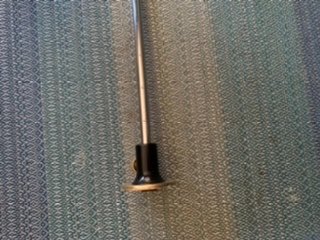
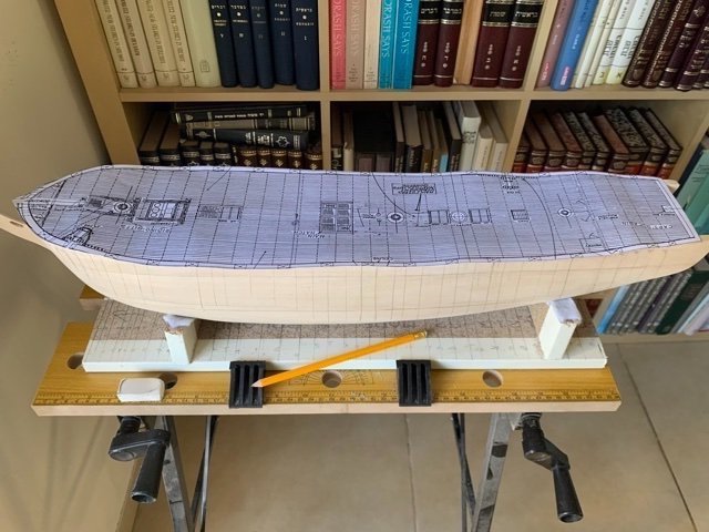
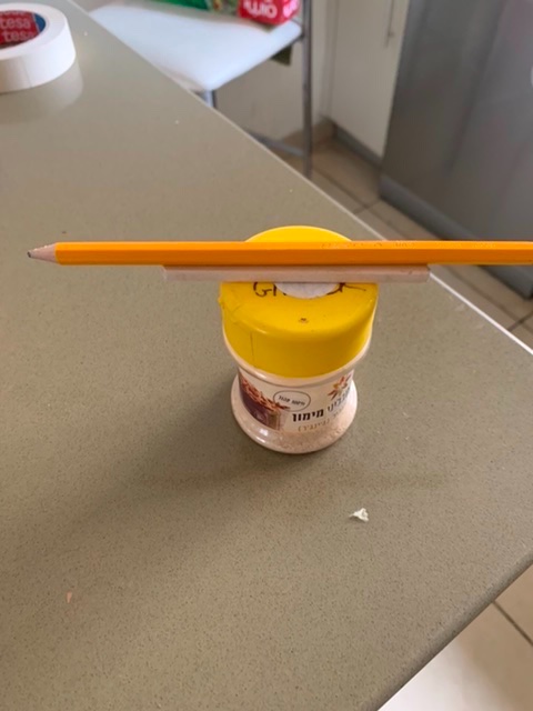
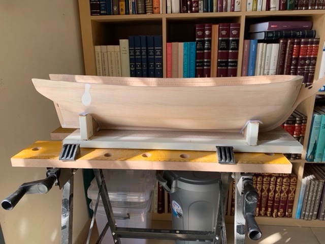
Now that it is in a cradle, I decided to readdress the waterline marking. I will need to do this several times, since I am marking it now, in order to align and cut the gun ports properly, but also again after I prime and paint the hull. Might as well get it done though. There are two challenges here: Get the elevation of the hull correct. Since the waterline at the bows is 20'0" (at scale, 2.50"), and at the stern it is 22'0" (at scale, 2.75"), I need to tilt the bows up to make them both parallel. Create a mount that can hold my marker (a pencil) at precisely the right height). My process: Use the profile template to mark the waterline at the bows and stern. Interestingly, at the bows it was right at the bottom edge of the rabbet for holding planks in the knee (is that part still considered the knee?). That made sense. In the stern, it was about midway through the height of the rabbet in the sternpost. I measured it at least 4 or 5 times, so I am comfortable with it, but it is odd. Create a harness such that the point of the pencil is precisely at the waterline marking at the stern. Use different pieces of scrap wood at different locations until the pencil in the harness is at the waterline mark in the bows. Move the harness all around until I have a waterline marked. Do this lightly, so pressure doesn't bend or tilt it. It thus required several runs. For elevation, the remaining length of keel after it was shortened to fit the hull length was perfect. It is ¼"x3/16". I placed it just behind the forward supports in the cradle. For the harness, I tried many different things - different mugs, spices, peanut butter case (my friend the doctor has a new company of fabulous peanut butter called "Holy Butter"; the interesting marketing opportunities when you are selling from the holy land 🙂 ), cans, you name it. In the end, it worked perfectly with a ginger container, on top of which I placed the rudder (yes, I could have used any scrap of 3/16" thickness, and will for the next time, but the rudder was right there), then the pencil, and taped it. Everyday kitchen appliances for detailed woodwork. I feel like MacGyver!
-
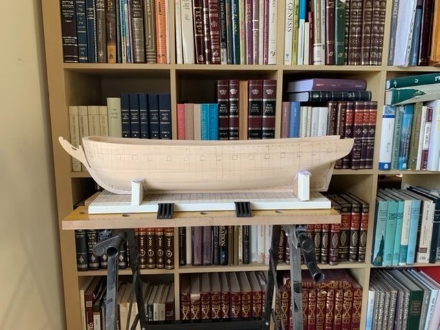
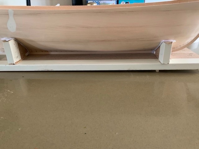
Took a lot of work, but she’s in the working cradle and the wood block is removed. Big day! (I’ll fix the picture orientation next time I’m on my laptop)
-
On to building a work cradle. I’ve looked at the smaller one in @KHauptfuehrer’s log and the larger one in @jfinan’s log. I tried to build something like the larger one without much success. First, the instructions recommend 3.5” high. Given that the waterline is about 2.5” above the keel, that would make it impossible to plank and very difficult to do a lot of the other carving (gun ports, etc). So my first cut will have to be cut down. Second, finding the right materials was an issue. I’m not planning on buying a professional router, so was hoping to use the router attachment on my dremel. I first tried some discarded cabinet from a renovation, all ¾“ plywood. I’m not sure what wood they used, but cutting through that broke 2 bits. Then I got the idea to use some old MDF from unused baseboards of an ikea cabinet. It didn’t break the bits, but still was quite difficult to get precise enough to shape. I did sand it down after cutting, so it’s better, but far from what it needs to be. Do the above builders have suggestions?
-
Perhaps @MrBlueJacket I’ll give the next set a few hours next time I use it. I’m heading stateside on business soon. Any good CA brands I should pick up?
-
I will say, I was not overly pleased with how tightly the CA held the wood of the various parts (stem, keel, sternpost) to the hull. Both were sanded down very smoothly (I used ~400 grit for final passes on everything). It also was a newly opened bottle of fine CA, so not likely to be that it "expired". Without the pins, I am fairly convinced it would not have come close to holding. I am open to advice on the matter, including links to more I can learn about using CA properly, or properly selecting brands (if it matters).


