


Avi
-
Posts
323 -
Joined
-
Last visited
Content Type
Profiles
Forums
Gallery
Events
Everything posted by Avi
-
The marquardt book consistently shows 6 strakes in the wales and 3 in the thick stuff above. My wales planks from bluejacket are ⅛” wide. 6 strakes at ⅛” per gives ¾”. The wales according to my calculation are about 0.6”, or slightly less than 5 planks (0.675”). I’ll either have to do 5 strakes and trim a bit, or trim a lot. the thick stuff planks are 3/32” wide. Three strakes comes out to 9/32” or 0.28”. My scale calculations gave them as 0.35”, or just smaller than 4 planks wide. I’ll have to choose between the correct scale, and the correct number of strakes. i think I’ll go for the number. If I do them both - 3 x 3/32” + 6 x ⅛” - I get 33/32” or 1.03”. Given that I’m looking at 0.95” or so for both of them, I’ll scale it up a bit and make it work.
-
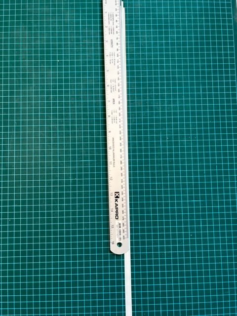
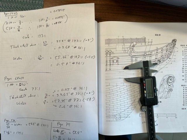
On to my calculations. With thanks to @JSGerson who was helpful, and especially @Tim Murphy from the USSCMSG who even spent time on the phone with me. i have a copy of the model shipways plans on order, should arrive in the next few weeks to help. Tim had a really good idea. The pages in Marquardt are all to scale. While it doesn’t have all of the belts, it does have the wales, the thick stuff above, and some of the thick stuff below. unfortunately, each page in the book is to a different scale. That meant calculating the scale for each one, then converting. Unfortunately, they also aren’t quite draftsman plans, so the measurements varied from one page to the next. I used primarily pages 74-75 (cross sections, especially figure D2/1), 68-69 (external hull, the face on view of the starboard bows and the side view of the same show the belts for the wales and thick stuff really nicely), 64-65 (profile view shows the same belts well). the really nice thing is that the wales and belt above each holds consistent width from bows almost to stern. Certainly more than enough to get started. I’ll include pictures of my work with pages 68-69. Due to the variances in the book (or more likely, my skills with calipers), I came up with widths: - wales: 55.66”-58.9” (3 out of 4 measurements were 57.75”-58.9”) - thick stuff above: 33.69”-35.3” while that is a few percentage points of variance, once I scale it down to my model’s 96:1, it basically doesn’t matter. Wales of 0.58” width vs 0.61”? The human eye cannot see it. I do plan to mark the lower belts A-D as well, even though I might not plank them except for A (thick stuff below the wales), but I will mark them and see. For that, I need the model shipways plans that are on the way. for marking, I’m using art tape. The white art tape I have is a bit wide for the purpose, but nothing that an xacto knife with #11 blade and a straight edge ruler cannot solve.
-
I see that there are the following bands of planks, rising from keel to caprail: bands "D" up through "B" - regular planks band "A" - thick stuff below wales thick stuff above - top of the wales the bottom sills of the gundeck gunports gundeck and spardeck (which can be done in various ways) The critical element here is getting the widths of the wales, the thick stuff above and below ("A"), and possibly "B" through "D". Even though I will be coppering, and therefore "B" through "D" will be covered by copper (and therefore probably won't be planked, but I might), it helps to position the bottom of the thick stuff and the wales correctly. Unfortunately, BlueJacket's templates and instructions don't really have those measurements. There is a page where it shows that the "wale strakes are 7" thick by 10" wide", which doesn't help all that much, unless you know how many strakes there are, and even then, the width changes as you move from amidships to the bows or stern. Working on some good solutions to this, definitely open to help.
-
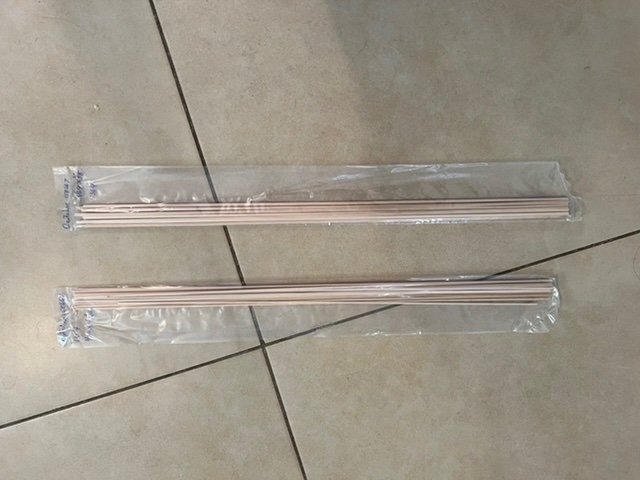
After a too long hiatus (including travel and a minor bout of Covid), my planks showed up this morning. I already had the regular planks. These are thicker ones for the wales and the thick stuff above and below the wales. I’m rather looking forward to getting back to it. I’m going to use the Anatomy and information from other peoples’ Model Shipways hull planking band guides to mark out the bands of the wales, thick stuff above and below, and regular planks, then start with the wales and thick stuff, eventually regular planks topsides and on the interior of the bulwarks.
-
Yes they have all I need. Worked through how much I need and what with @MrBlueJacket by phone, order will be placed tomorrow. Thanks for the suggestion @mort stoll
-
Heh I didn’t think of it. They probably would. It means waiting a while to get started planking - I absolutely want to do the wales first - but worth it.
-
That’s where I was starting to go @KHauptfuehrer, and was looking for that picture of yours. yes the BJ planking is 0.02” thick, or about 3/128”, halfway between 1/64 and 2/64 (= 1/32)”. i like your plan. So you used the BJ planks as is for the “thick stuff” above/below the wales, BJ planks sanded down further for the rest, and got 3/32” sanded down for the rest. I’m wondering where I will get 3/32” stock around here, or even what to call it. If I had an extra set of BJ planks, I’d even think of just doubling them up for the wales.
-
Oh interesting. Apparently the official definition of “thick planks” was >4 inches thickness. That would explain the wales and “thick stuff”. If I can get the right dimensions on those, I’ll be in business
-
> Constitution‘s hull planks are on average 35 feet long, vary in width from 5-7 inches, and 4-7 inches in thickness. from official museum page still not exact, but getting there
-
I’ll add that @ERS Rich was super helpful, shared what the Model Shipways (which planks to the keel, as it is plank on frame) model describes. - keel to wales: 4 belts of 9 strakes each - wale: 7 strakes - thick stuff above the wales to lower gunport sill: 3 strakes - gunports: 4 strakes - above gunports to planksheer: 4 - planksheer (which is sill of spardeck gunports) - planksheer to main rail: 4 - main rail to top rail: 2 Interestingly, the MS has the following thicknesses: - 3/32” wales - 3/64” above the wales (no distinction between thick stuff above the wales, 3 strakes, and side planks above those) - 1/16” below the wales (no distinction between thick stuff below the wales, 3 strakes, and side planks below that) so it does recognize the different thicknesses, but treats them somewhat differently. I’m very grateful to @ERS Rich for helping share perspective. I think I’d like to get at least the wales a bit distinct, even if I cannot quite get the thick stuff above/below to be distinct from the side planks. I definitely will try to do the bands, though. Given that bluejacket is plank on solid hull, the actual thickness doesn’t matter, only the relative thickness. I’ll go hunting for some information on the actual thicknesses of the wales, thick stuff, and side planks on the real ship, to determine how much they “stick out” relative to each other. Divide by 96 should give an answer as to how much thicker the wales should be than the bands above or below. i may find this to be a fool’s errand, that the difference, scaled down to 1:96, is so tiny that I cannot make it happen. But I’d like that to be a conscious decision.
-
> shows 3 do you mean 3 thicknesses @KHauptfuehrer? It looks like there’s a “step” inwards between the wales and the next band up (“thick stuff above the wales”), that next band being 3 strakes. And it looks like there is another between that band and the gunport band. is that the “3” to which you refer? > really is your choice i know. But the more input I can get on how it really is and was built from experienced smart and helpful people like you, the more accurate I can make mine.
-
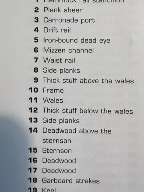
As I prepare to plank, it’s a long new journey, learning about some of the terms, how to bend planks, spiling, bands, etc Most of the guides here are for full on planking, ie keel to sheer (or wherever). They mostly discuss separating the section between wale and keel into 4 sections, etc. That isn’t very relevant here, as all of that will be under copper. Even above the waterline, though, I’ve found some conflicting info. the bluejacket guide states: > there are no thickened wale strakss that mostly fits with what is in the guide’s pictures. however, it doesn’t sit well with what is in “Anatomy of the Ship”. In multiple places (see picture), it refers to wales (about 5 strakes), thick stuff below the wales (3), thick stuff above the wales (3), and then side planks. Not quite sure what the right way to proceed is. Am I looking at 3 distinct thicknesses? Or just 1?


-
My problem: sanding my build scratches away paint. Working on the hull of my USS Constitution build, I sealed the wood, primed it with two coats, then put on two coats of copper below the water line and black above. Primer and paints are Vallejo acrylics Model Color. Once fully set (I waited days) I tried sanding to smooth down the paint where needed, etc. I used 2000 grit wet, which should be high enough. I moved very gently in circles, using only light thumb pressure. It didn’t go so well. It smoothed it beautifully, but also removed paint, to the point where I could see the primer or wood underneath. That definitely wasn’t the goal. what am I doing wrong? Isn’t high grit wet sanding supposed to be good at smoothing it without scratching away the paint?
-
Well I tried sanding to smooth down the paint. It didn’t go so well. Fortunately this will all be covered with planking or copper, so the blemishes don’t matter, but I would like to understand why, so I can get it right when it does matter. I tried wet sanding the copper and the black with 2000 grit wet. I moved very gently in circles, using only light thumb pressure. Basically trying to smooth out where there is buildup of paint, or raised anything (might be dust that got in). It smoothed it beautifully, but also removed paint, to the point where I could see the primer or wood underneath. That definitely wasn’t the goal. I will post a new thread to the painting techniques forum. Open to answers here as well.
-
Second coat of black, and two coats of copper (second coat of copper still drying). It looks like it could benefit from a third coat of copper, but since this is just the extra hiding under the copper plates, I will not bother. Both the areas - black and copper - could use some wet sanding of very high grit. I will get to it next week (take advantage of Christmas to New Years quiet time). I accidentally touched the stem with the black paint. I could sand it off, but it’s a hard angle, and since it will be covered anyways, it doesn’t matter. Side note: I really enjoy seeing the copper flakes in the paint.

-
Picture after first coat of black paint on topsides and interior. It’s taking some experimentation to find the right mix of paint and thinner, but as this will be covered with planks, it’s a good place. it clearly needs to dry, a light sanding, and a second coat. It doesn’t *really* need it, as planking will cover everything, but it’s good practice for ahead when precision will count more. You’ll see that I decided to paint the interiors of all of the gunports on both decks black. The manual is somewhat confusing, and implies that it might be white, but the current ship clearly has black in the pictures, I like the look, the manual wasn’t clear, and we don’t have any colour pictures from the early 19th century anyways. 😃 This isn’t my usual location, as you can see. Inclement weather, had to work indoors. It’s a good thing I’m using acrylic paints, and I put plastic sheeting to protect the table.

-
That is art right there. Absolutely beautiful @ERS Rich
-
The experiments were a good idea. no pics to post for now. I wiped the hull extra clean with microfiber cloth, then put on a coat of sanding sealer, let it dry, and sanded it with 400 grain. It was really interesting to see how it brought up the fibers and grain. I sanded one side, then brought it to my wife to compare the two sides. Was pretty cool. i decided on only one coat of sanding sealer here, as it is all going to be under the planks or copper. i added a single coat of Vallejo Medium Primer on the entire outside of the hull, and the inside of the bulwarks. I plan on sanding it after it dries, but as it says it takes 12 hours to cure, I’ll let it sit a day. I had to experiment a bit with thinning. At first I thinned it 50/50, but it gave barely any coverage at all. I remembered that it is supposed to be the consistency of milk, and realized that the primer itself already is that consistency. Further, it says on the bottle that it can be loaded into an air spray can as is, so I guess it already is pretty thin. i did the rest of the first coat without any thinning, got much saner coverage. It still isn’t a smooth grey cover, which surprised me as it is unthinned primer, so I guess it needs another coat. Tomorrow I will sand it lightly and add another coat. After that dries, I’ll give it another light sanding, then paint. I’m happy to hear thoughts about what to expect after a coat of primer on top of sealed wood.
-
Acrylic paint tips and techniques
Avi replied to Canute's topic in Painting, finishing and weathering products and techniques
Got in touch with the local manufacturer, turns out his product is sort of sealer that gets absorbed plus varnish in one, definitely not intended for painting or any other layer on top. Back to square one. I may have to suck it up and either buy the DecoArt or the Varathane or the Mylands. Mylands is cellulose, so thinning will be smelly. So is the varathane. Oh well. UPDATE: The Varathane is water-based, easy to clean up, no spills. I know, not as good as the cellulose, but good enough for my usage for now; trade-offs. Local importer was out, along with most of his retailers, but one still had. Ordered it, should show up in a few days. -
Acrylic paint tips and techniques
Avi replied to Canute's topic in Painting, finishing and weathering products and techniques
I also am going the Vallejo route; it was just the easiest high quality to acquire here in Israel. Although I do travel regularly to the US (well, depending on covid restrictions), and lots of Amazon ships here, most paints do not. As for the Clou, I have not found it outside of Germany either; I looked in Israel, UK and US. How would I evaluate the quality of a local/imported brand? Or find the right USA-based ones to order on Amazon? So far, I’ve seen a lot on the decoart Americana multi purpose sealer (which is ~$5 for the 8oz bottle on Amazon but doesn’t ship here, and is about 2x that here), and then larger ones like 0.5L mylands and some local ones that come in litres or more. and I have found the rustoleum varathane premium sanding sealer -
Acrylic paint tips and techniques
Avi replied to Canute's topic in Painting, finishing and weathering products and techniques
Do you mind linking to some sample brands? -
Acrylic paint tips and techniques
Avi replied to Canute's topic in Painting, finishing and weathering products and techniques
If I get what you are saying @wefalck, any combination will do in the end: paint straight on the wood with lots of coats and sanding, primer straight on the wood with several coats and sanding and then the paint, sealer in 1-2 coats with sanding and then paint, sealer and then primer (if needed because of the specific paint color) and then paint. All will stick well. It is just a question of what combination works for your needs in terms of minimizing wasted coats as well as covering up imperfections. What you put on top of the paint, if anything, is there to protect the paint itself, for which I have varnish (and can get the recommended wax, although that’s glossy). Is that about it? What do you use for sealer? -
Acrylic paint tips and techniques
Avi replied to Canute's topic in Painting, finishing and weathering products and techniques
Ouch. Just discovered this thread, which left me even more confused. So I can deal, or not seal; use the primer as a sealer, or not. Or I can use the poly varnish as a sealer coat. The more I learn, the more confused I become.😕 -
Acrylic paint tips and techniques
Avi replied to Canute's topic in Painting, finishing and weathering products and techniques
Oh yes. I’ll look into renaissance wax. But isn’t that more of a glossy? speaking of which, although a bit off topic, I’ve been thinking about how to protect the copper plating over the years. Due to oxidation, it’s likely to turn green. I’d heard about people putting a coat of copper paint on it. I’m wondering if gloss varnish or renaissance wax would help. -
Acrylic paint tips and techniques
Avi replied to Canute's topic in Painting, finishing and weathering products and techniques
I think my favourite suggestion you had was not to worry too much, just experiment away on scrap wood. 😀 any particular sealer?

