HOLIDAY DONATION DRIVE - SUPPORT MSW - DO YOUR PART TO KEEP THIS GREAT FORUM GOING! (89 donations so far out of 49,000 members - C'mon guys!)
×


Avi
-
Posts
323 -
Joined
-
Last visited
Content Type
Profiles
Forums
Gallery
Events
Everything posted by Avi
-
Thanks for the detail @vaddoc so you recommend a sealer and a primer? Or the sealer instead of the primer? It was @MrBlueJacket who said he always uses primer but not sealer, at least on the hull. He does sand lightly in between coats, too. > thin to a consistency of milk whole milk, 2% or skim? Each has a different consistency. i think your point is that if I make it too thin, within reason, it just means more coats, but no other downsides. If it’s too thick, then I’ll have many issues. also, do you thin primer? I’m guessing same consistency target as paint? finally, any particular recommended sealers? Thanks!
-
Acrylic paint tips and techniques
Avi replied to Canute's topic in Painting, finishing and weathering products and techniques
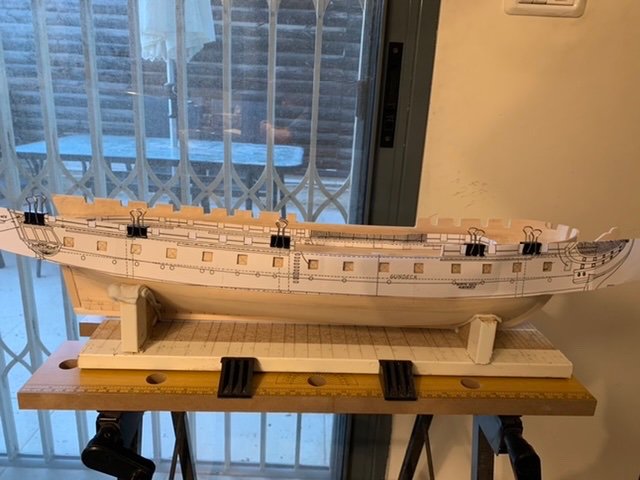
This has been a first class helpful thread. Thank you all for contributing! I’m about to start painting on my build. I’ve been shaping the hull, cutting gunports, adding keel, etc for most of this year. I plan on planking, first going to paint the hull black, so anything visible between planks looks like pitch, and copper on the bottom. I have Vallejo Model Color paints, as well as their thinner and varnish (matte and gloss). Some questions: - the bluejacket person said he usually puts several coats of primer (sanded lightly between coats) directly on the hull, no sealer, then paints. This thread implies sealing first (or instead) would be better? Or is it just various techniques? - how much do people thin their acrylic paints? primer? varnish? - I was going to paint the planks, but I prefer to stain them directly, so it keeps the wood look. This ship will be handled. Should I varnish after? How would that affect the look? thanks to all. -
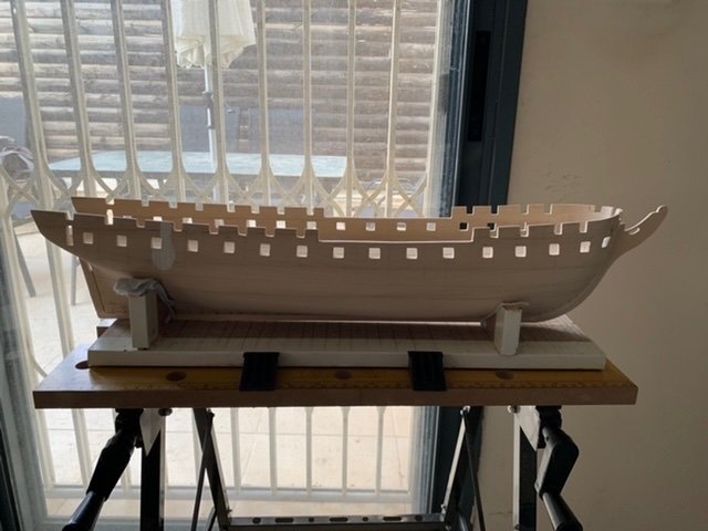
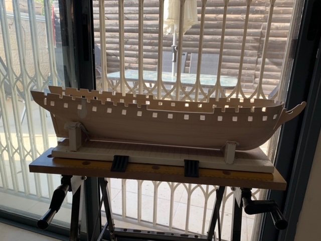
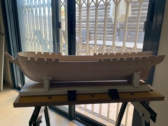
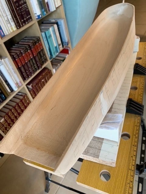
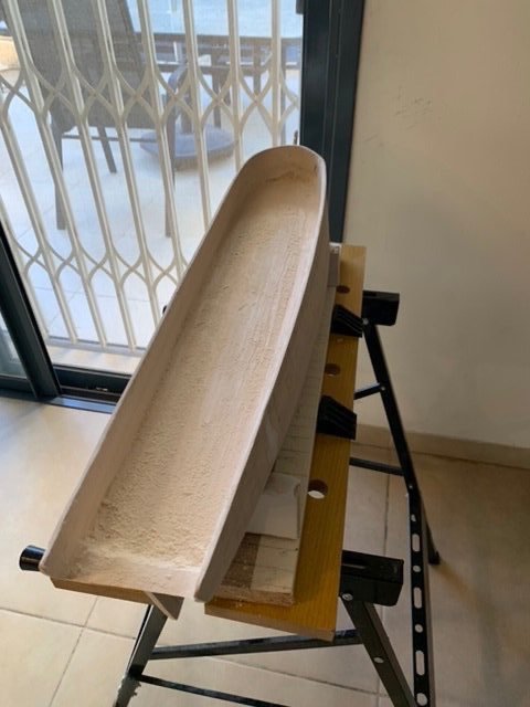
One last picture before I start with painting. I’m really liking how nice this looks with the gunports! I’ll be following @MrBlueJacket’s suggesting of priming and then painting the hull before planking and coppering. A few coats of primer, lightly sanded in between coats, directly on the wood, then the paint. Black on the inside of the bulwarks and outside above the waterline (“topsides”?), so that any gaps between planks look like pitch in the seams, and copper below the waterline, so any gaps don’t show at all. I’m using Vallejo acrylic Model Color paints and will be hand brushing everything. I have their thinner, so I’ll have to experiment to get the right viscosity. I hear a lot about 2:1 paint:thinner, or even 1:1. I also have to figure out whether to thin the primer, and if so, at what ratio. I’ve been browsing the topics on painting at MSW, lots of interesting info, nothing definitive for me though.
-
Having reread the manual, that “hump” is the ⅛” I left “above the gundeck”. I assume that is to ease constructing everything at the stern. Either way, the gundeck clearly is at the level of the top of the block of wood (which fits with the conveniently pre existing camber), so I will file those two doorways down further, hopefully getting a decent height. Done. The bottoms of the doorways are just above the top of the wood block deck area, which should leave just enough room for the decking itself, and a bit of a door sill. And they measure out precisely at ¾”, scale equivalent of 6’. No idea if that’s what it actually was in 1812, but I’m happy with it. On to sanding, then it’ll be time to learn how to use the paints.
-
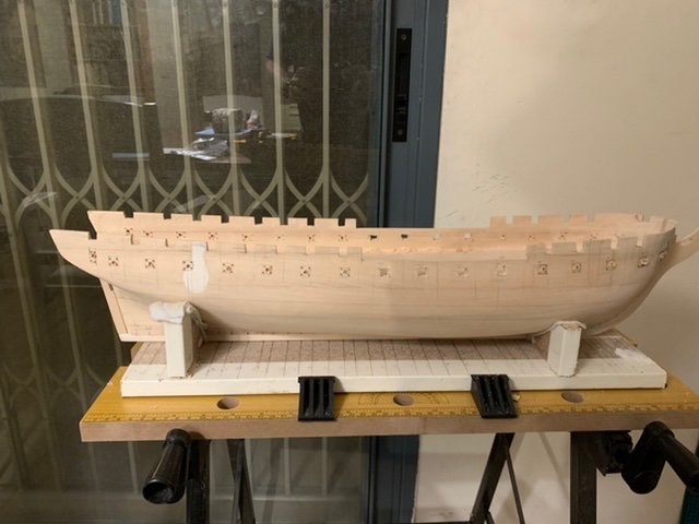
Gunports all filed out. Basically flat file for the size and sides, careful usage of square file for the corners. Looking closely, these are not quite done. I still need to sand them down, both for fine touch of shape and for smoothness. One interesting point is the last “port” on each side, which isn’t really a port at all, but the doorway into the quarter galleries. It doesn’t appear on the plan profile, but does on the deck layout. The width is somewhat less than a gunport, using the deck plan it comes out to 7/32”, which I transferred as is. One of them came out slightly larger, but as it is a doorway, and will be behind the quarter galleries, I don’t care. To calculate the height, I filed the bottom of one down until a bit below the level of the gunports, which should be close to the gundeck, then upwards a reasonable amount without hitting the spardeck or weakening the wood in between the doorway and the gunport opening above. I then measured it and transferred to the other side. I would have liked to make it exactly ¾”, which at 1:96 scale is exactly 6 feet, but didn’t have the headway. Then again, the bottom actually is not level with the gundeck now, but with the extra “hump” of wood left athwartships at the stern. So I might have room to file these down further and get my full ¾” (or closer). I need to read ahead to see how the “deck” surface of the pre carved hull, the gundeck itself, and the extra “hump” come together.
-
Yeah I had to adjust it a bit while clipped on as I worked through it, but it worked out pretty well. Busy expanding the gunports to the appropriate size. It is a slow process, done about 10 out of the 34 so far. But they look great when done.
-
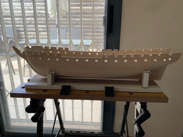
And with all of the gunports cut out! As mentioned above, these are far from final. Next step, I will use the gunport lid to get the right size and shape (square 😁) for each port using files, mainly flat and square. Then sand them down.
-
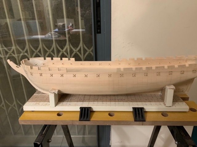
Gundeck gunports nicely marked, thanks to the @mort stoll template system. Proceeded to begin to cut out the gunports. The manual recommends using a 1/16” drill bit to drill in each corner and the centre of each gunport, then connect them with a keyhole saw. I did that, then realized that my saw is just slightly bigger. Fortunately, I had put my drill holes inside of the outline, with some room to spare, expecting to file the ports up to size. I went back and used a 3/32” drill bit, which did the job nicely. I then cut between the holes with my keyhole saw. That popped a small misshapen block of wood out from each. Then I filed the ports. be careful to leave a little extra room so you can expand the hole if needed. so far, I have done only four on each side. They aren’t remotely finished. They almost certainly are too small, not to mention in desperate need of sanding. My plan is to get all of the ports to this state, and then I will file them until one of the gunport lids just fits. Even messy and small, I included a photo to capture the progress.
-
That was a genius idea @mort stoll Look at the attached picture. I cut the tip of my template out at the top of the bulwark (ie bottom of the caprail). For the bottom, I cut the bottom loosely well below the gunports, and then cut out each gunport with a nice sharp xacto knife. I can just clip it to the hull, aligning the top of the cutout to the top of the hull, and just mark out the gunports. the bridle port is almost all the way at the bows, and so distorted by the curve, so I didn’t cut that one out. But it should be easy to extend the line just for that one port.
-
I thought about that, but I was concerned the profile was a projection onto 2D, and doesn't account for the z-axis curve; if I curved it back in, it would be misshapen. Or maybe it wouldn't. Perhaps @MrBlueJacket knows about the layout of the profile and its projection?
-
Spardeck ports are basically done. Used internal calipers to transfer each port, as described above, then files to get it to the right width and height. The width appears to be consistent across all of the ports, but not the height. A few things I haven’t done yet: 1. Decided if I will line them. If I do, I need to add some more width and height to make room for the wood lining. I will decide after doing the gundeck ports. 2. sand then down. Not much point if I might need to file them larger for step 1. 3. The last port on the port side, aft side of the port, angles up towards the top of the bulwark, making it too large. If I decide to line the ports, this will be fine; if not, I will fill it in and sand it down. Either way, I need to wait for a decision on step 1 first. On to the gundeck ports. First, I’m hoping to get some comments on my question above about how to align the gundeck ports.

-
Used inside calipers to measure the 4 spardeck gunports forward of the opening in the bulwarks. All have the same width, all have the same height (or so small as to be immaterial). Kept my calipers open at that width, and filed left and right sides of all 8 (or those that needed it) until the calipers just fit inside. Then set the calipers to the height, and filed the bottom of the few that were too short until the calipers just fit inside. Then used square calipers to get the bottom right and left corners to be good. These now are precisely right. Will move on to the spardeck gunports aft of the midships bulwark openings. Then I will deal with the openings for the bowsprit and catheads. I haven't decided yet about using their recommended 1/32" stock to line the inside of the gunports. If I do, I will need to file off some more on the sides and bottom of each.
-
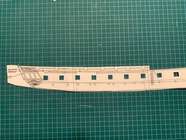
Next struggle: how to get the gundeck ports exactly right. Since they need to be exactly bordered on top and bottom by the plank strakes, and will have a white band painted to boot, positioning becomes really important. As far as I can tell, they are not parallel to the keel, nor to the waterline angle, but have a bit of a convex curve to the line, with the lowest point around midships, curving upwards quickly towards the bows and more slowly towards the stern. This seems to fit with both the profile blueprint and the architectural diagrams in “Anatomy of the Ship”. Did others find the same curve? How did you manage to measure and lay them out correctly?
-
Forgot to mention. It’s very easy to get used to the idea that the bulwarks are strong and resistant. Once you dremel/plane/chisel/gouge/sand them down to ⅛” thickness or so, they’re much weaker. Be sure to hold them with a hand near where cutting or filing. Most of the time I remembered. At one point I forgot and snapped a small piece off. Nothing some CA couldn’t handle, but it’s much easier to remember and not break anything.
-
Remeasured all of the gunports and various other openings. Finally got to start cutting then open, which surprised me how exciting it is! I’ve spent the bulk of work over the last months - possibly half a year - sanding and shaping the hull. Sure, there’s been finer work on the bulwarks, and the sternpost, keel, stem and knee were fun, but it’s been a long haul without seeing too much change. Now, in two days, I see the progress. It’s exciting! so far I’ve only cut those from the top of the bulwarks, ie spardeck level openings. I used a jewelers saw to cut the bulk of the openings. I intentionally cut them smaller than needed, but not by much. It’s easier to expand a hole than to correct if I cut too much. I then used files - mainly flat but also square - to shape and finish the openings. I used sandpaper on the large midships openings, starting with 80 and moving up to 400 grit. As you can tell from the attached pictures, I’m not close to done, but progress is being made. once I’m done with the spardeck level openings, I’ll do the gunports on the gundeck. My plan is to experiment with two different techniques. One is to drill small holes in each corner and then cut away with a keyhole saw. The other is to drill a larger hole in the centre, and the just use files to complete the opening. We will see what works. But plenty to do on the spardeck first.
-
I’m pretty much done shaping the bulwarks. They’re the right thickness, and, after using progressively higher grit sandpaper up to 400, nice and smooth. There definitely are spots where I wish it were slightly more straight or flush, but as I plan on a thin layer of CA before planking, I should be fine. you can see at the bows where I dremeled too much and had to fill in with putty, then sanded it to shape and smooth by hand. pictures attached. next step: on to remeasure the gunports and opening in the spardeck bulwarks amidships, and cut them open.
-
Just came across this. Do you know of a decent guide (or thread here) to understanding the difference between nibbing and hooking? I’m building a constitution model (see my other thread), and while I’m clearly a few months away from dealing with it, it does affect the waterways, which is part of the planking, which is rather soon. The bluejacket guide has a single pair of diagrams which seems to indicate that the ends of the planks are underneath the waterways. That makes no sense, as the deck planks are flush with the waterways in every diagram and picture I have seen. In any case, as @druxey stated above, nibbing is a later development, while the model I’m doing is 1812-1815. So, how do I understand both?
-
The putty sanded down beautifully. Once the paint and planks are on, it will be invisible. It also looks like I didn't Dremel too thin anywhere else. I might have a chunk of hand sanding left to do, especially using the contour sanders, but that is ok.
-
It turned out to be a great idea. I had to be very very careful, and even then I dremeled it too thin by the starboard bridle port and had to put a nice thick layer of wood putty on it, but other than that, dremel was far easier. I even got to the outward curve from the bottom of the spardeck towards the bottom of the gundeck. In figuring out where to begin that curve - bottom of the spardeck- I did the following 1. measure spardeck line on the profile above each gundeck gunport using external calipers 2. transfer the line to the model, where I already have the gunports marked 3. measure those spardeck markings from the top of the bulwark using outside calipers 4. transfer the marking to the inside of the hull 5. connect them all with a marking gauge I decided to check the top of the bulwark from the spardeck on the profile and compare it to what I had on the model. My model had a solid ⅛” in many places. Looks like my model needed the height of the bulwarks trimmed down. I verified it by measuring the height of the top of the bulwark on the profile from the gundeck, then comparing to the model. Sure enough, I needed to trim it down. shoulder plane did a fantastic job, followed by some easy hand sanding. I then took my marking gauge, set it to ⅛”, and remarked the thickness of the bulwarks. Then used a chisel to remove the inside, hand sanded some, then on to the dremel as above. in the end, I finally have the bulwarks where I want them. Remaining: - wait for the putty to dry and sand it down - gouge the angle where the bulwarks meet the gundeck, to get the right angle and to make room for the waterway - hand sand all of the inside to get it as smooth as it needs to be to attach planks. If there are areas where I dremeled too deeply, I’ll fill in with putty or thick CA glue.
-
Dentist? Funny, every time I use the dremel I think of my dentist! 😂
-
@Jerry Berenson she’s a real beaut! You’re only a year in? I find that progress amazing. Yeah I’m spending a _lot_ of time thinning those bulwarks. I used chisel and plane where I could, but I’m finally at the point where it just needs to be hand sanded. The most surprising part is some of the harder “striations” (for lack of a better term in my limited knowledge), where the wood doesn’t want to wear down under the sandpaper. It’s been a long haul. I’m close. after that I still need to finish the bows - my recently acquired external calipers show about ¼” when I need to get then down to closer to ⅛” - and then getting that inward curve. I even could live with having sanded down a bit too much, as a thicker layer of wood glue, or thick CA, could smooth it out. But if I don’t get it thin enough then I’ll have the issue you raised; and if it is not smooth and uniform enough, it’ll make attaching the planks very challenging.
-
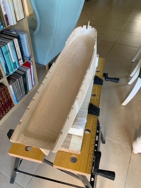
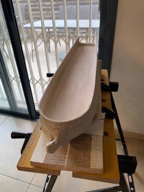
Not quite done with shaping yet. It’s been a long haul of back and forth between block plane, shoulder plane, sander, chisel and gouge over and over again. I’m almost at the point where the bulwarks are the correct thickness and 90 degree vertical from the aft end of the bow curve all the way to the stern. Almost. It needs a few more runs of all of those tools. Then I need to return to the bows, which is harder to do both because of the curvature towards the bow, as well as the inwards curve on the vertical from the caprail in towards the gundeck. My current calipers (digital pair, in one of the other posts) is not one of those pincer shaped ones, so it doesn’t help here. I’ll pick up a proper simple outside calipers like that next week. Speaking of the bows, there was an enormous amount of material to remove inboard. I started by gouge and chisel, realized it was absurd, so I broke out the dremel with sanding drum. 10 mins of dremel saved me many hours of hand effort and frustration. Speaking of frustration, there have been spots in the wood where the texture got harder or, well, grittier. For the harder, it become very difficult to sand those down, leaving a pronounced ridge line. I used a gouge, cut through all the way down, then sanded smooth. For the grittier parts, it was just strange, the plane would get stuck, felt like a car going over gravel that’s too thick, bump bump crunch. Just lots of gouging and sanding for those spots. Once all of that is done, I need to get the inwards angle for the gundeck. My plan is to use my marking gauge to mark the bottom of the spardeck (or more likely the midpoint of the deck itself, between bottom of spardeck and top of gundeck), and then use a combination of gouge, chisel, sanding block/contour sanders, and planes and cut on an inwards angle. Attaching one picture for the current state.
-
Sorry to be a bit slow in posting. The Veritas importer replaced the block plane, new one works just fine. It doesn't work on the entire hull - anywhere there is an inwards curve, i.e. concave, it cannot get to the surface. But for most of the bulwarks, a combination of the mini block plane and mini shoulder plane has worked. I pretty much am at the limit of what those can do, am going to break out the chisel and gouges. They will handle both the very aft of the bulwarks, where they meet the slight raising of the hull where the counter will go on the outside (per the instructions); as it is both raised (so the plane cannot get closer than about 1cm to it) and curved inwards, and the bows, where gouging is pretty much the only way to remove all of that word on that double curve (port and starboard towards the very bow, and inwards from caprail to gundeck. Fortunately, I had the Veritas tool vendor throw some of those sharpening paddles - plastic paddles with diamond "sandpaper" (not sure what they actually are called) and Arkansas stones of various shapes into the delivery package, so I should be able to sharpen them correctly. And hopefully avoid my fingers this time. 🙂 Some pictures will be forthcoming once I make more progress.
-
I like the idea of holding it in a vise. And I have the perfect one for when I need to shape other things than the hull. for now, the shoulder plane (albeit too narrow compared to the block plane) is shaving nicely, I got a lot off. It will require more sanding to smooth it out, but it did a nice job.
-
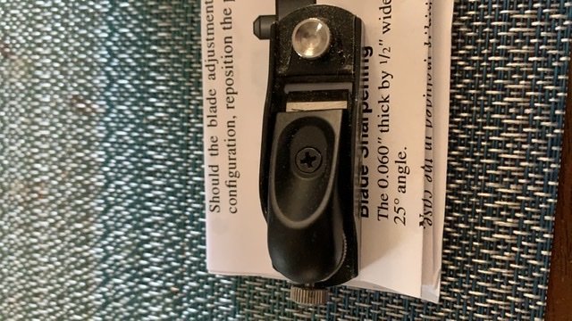
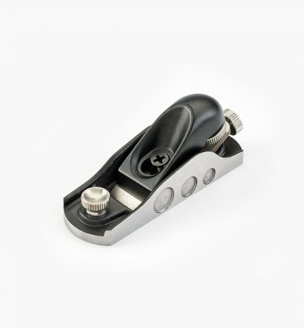
@ERS Rich the planes were a good idea. Almost. I spent quite some time trying to figure out why the mini block plane wouldn’t cut. Eventually I called their excellent support in Canada, who spent an hour on the phone with me. Eventually we realized that my tool was defective. The screw that holds the cap iron in place is supposed to be in a slot, so the cap iron can slide backwards and forwards to adjust it, which puts the right pressure on the blade at the right place to get a cutting angle. Mine is a single screw hole, so it cannot adjust and will not cut. Support guy had me remove the cap iron entirely and hold the blade down by hand from on top. Lo and behold, is shaved wood like a charm. My local retailer is going to check it and get back to me. Veritas support even offered my retailer to call him if needed. Those veritas tools are not cheap, but the company does stand behind them. Attached the picture of my plane, and the one from veritas site.