HOLIDAY DONATION DRIVE - SUPPORT MSW - DO YOUR PART TO KEEP THIS GREAT FORUM GOING! (Only 13 donations so far - C'mon guys!)
×


Tim Holt
-
Posts
196 -
Joined
-
Last visited
Content Type
Profiles
Forums
Gallery
Events
Everything posted by Tim Holt
-
 Ah sorry for the Swift confusion. It’s the AL Swift 1805 - the little cheap kit. See And I can see when I get back to my computer (on phone now) I’ve got some good reading and references. Thanks for that!
 -
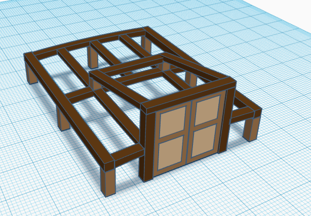
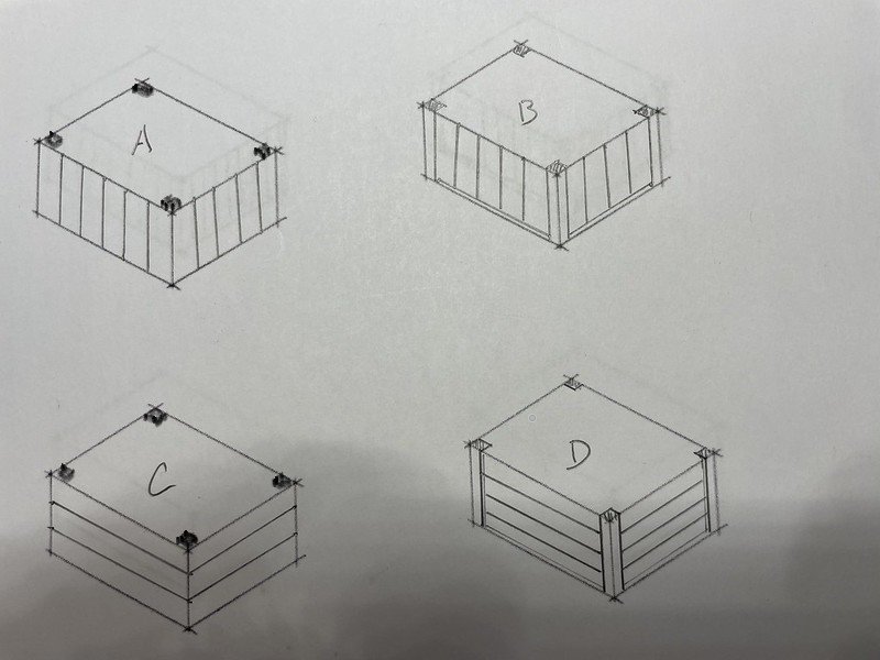
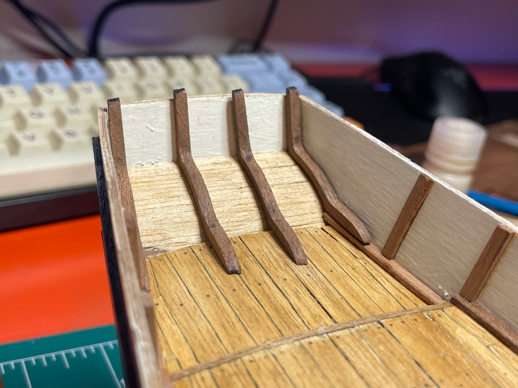
I'd imagine that a companionway might be framed something like this for example. The beams may be a bit too oversized, but it gets the idea across. But then I'm just making this up so any insights of how this might actually be done would be useful.
-
On my meager AL Swift 1805 build, I'd like to build the cabin up with more traditional framing rather than just pieces of ply with thin wood glued on. The instructions show basic vertical orientation of the siding, as well as no visible corner post. For the real thing, it seems there would be some framing inside to give it overall structure, and at least on most all land structures, siding is oriented horizontally rather than vertically. Here are some quick sketches of how I imagine the real thing might be constructed, where... A is as the kit essentially says to do it - no visible corner posts with vertical siding B is the same, but now the corner posts are actually visible on the exterior C is no visible posts with horizontal siding D is visible posts with horizontal siding Assuming this is going to be left bright and not painted, the visible posts option does seem to offer a nicer aesthetic with a contrasting wood. But would you actually build it that way in real life?
-
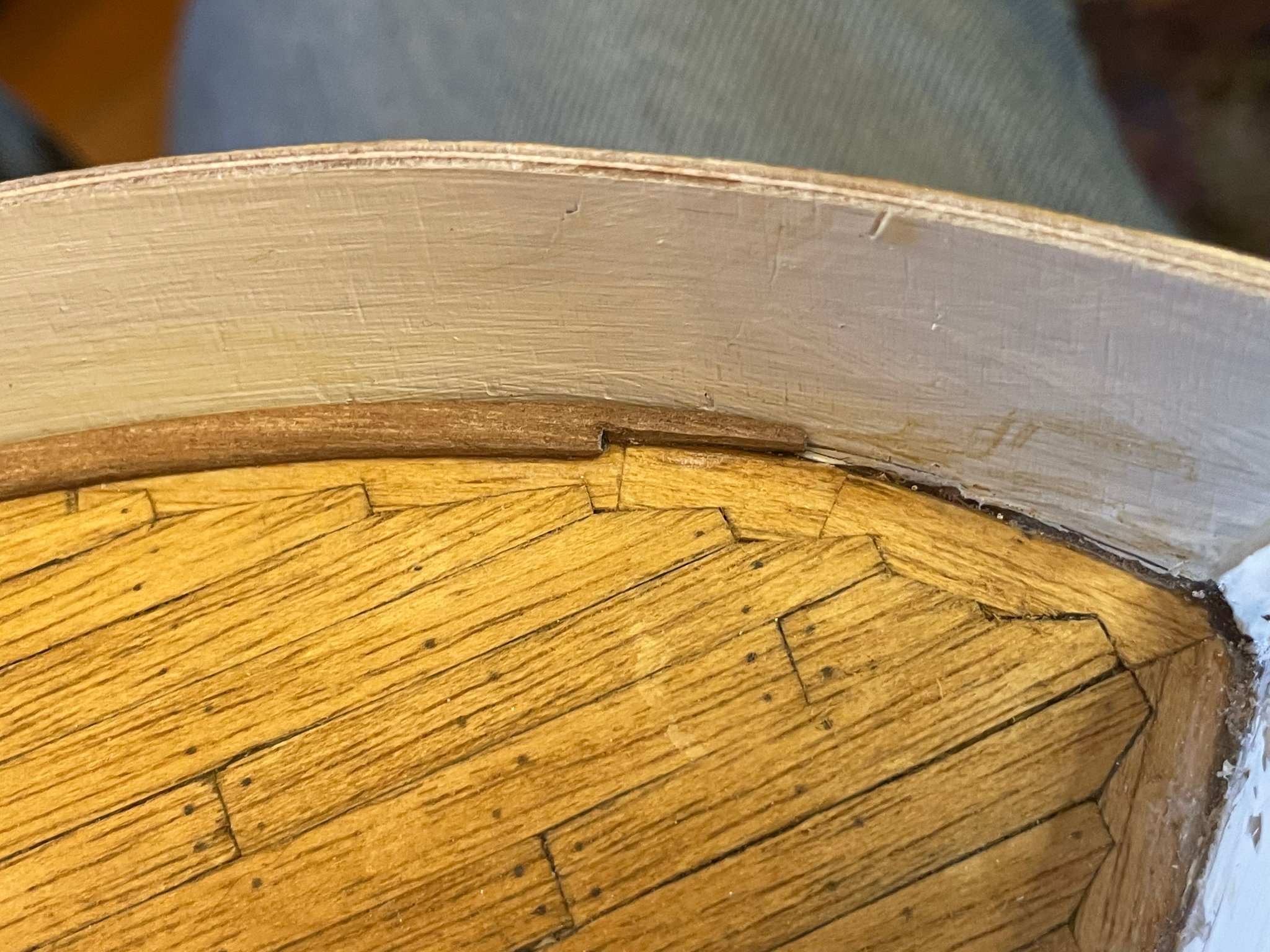
Update for the last few days. First up, I redid that hatch coaming I'd done before. My joints were rather gaping and so I rebuilt with lapped and stacked 1/8" square mahogany. Gluing up... Then on the deck... Just a dry fit right now, and it needs a bit of chamfering and such to finish it up. You can also see the coaming base in place for the rear cabin. Probably going to just frame and build one up from smaller square stock for corner post, then planking for siding. I also got the top rail on as you can see. All stained with Minwax Jacobean (really dark) and glued on with CA. What I won't show you is how the very front of the top rail doesn't exactly line up with the keel - an issue I didn't see until after I took some pictures. Probably have to saw it off and make a new one with the right fit. It's kind of nice to have a "make the mistakes and learn" model to start with.
- 44 replies
-
- 1
-

-
- first build
- Artesian Latina
- (and 1 more)
-
Thanks Chuck. I'd not thought of the laser cutter bed size, but that also makes sense. I've got access to a Glowforge at work (~20" bed width), but as you point out, scale lengths is also a consideration.
-
I've got a sizeable piece of Alaskan Yellow Cedar - about 8" x 10" and maybe 10 feet long. It's rough sawn. I've contemplated cutting it up into shorter lengths and then into usable wood for future projects, but not sure about what size, or whether I should even bother until I have a specific need. I could cut and mill it down into say 4" x 4" blanks for later cutting into thinner/narrower pieces, but then I'm not sure about what length to cut. Syren Ship Model Company sells pre-cut pieces, mostly only 14" long, and I'm not sure if 14" is because all they had were short pieces of wood, or 14" is more than versatile for anything you do. Any advice?
-
In the previous comment, I mentioned using some mystery wood from my father's old instrument making days. I've got quite a bit of interesting wood from this, including pieces of mahogany, ebony, maple, and actually quite a bit of Alaskan Yellow Cedar (8" x 10" x 10' single piece), plus a lot of Port Orford Cedar. At some point I'd like to mill up some of the AYC with an eye towards using it for a model some day, but not until I a) work on some basic skills, and b) have a really clear project for it.
-
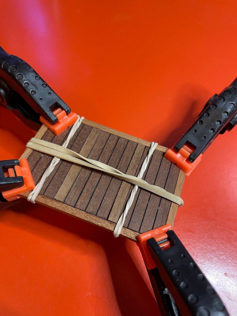
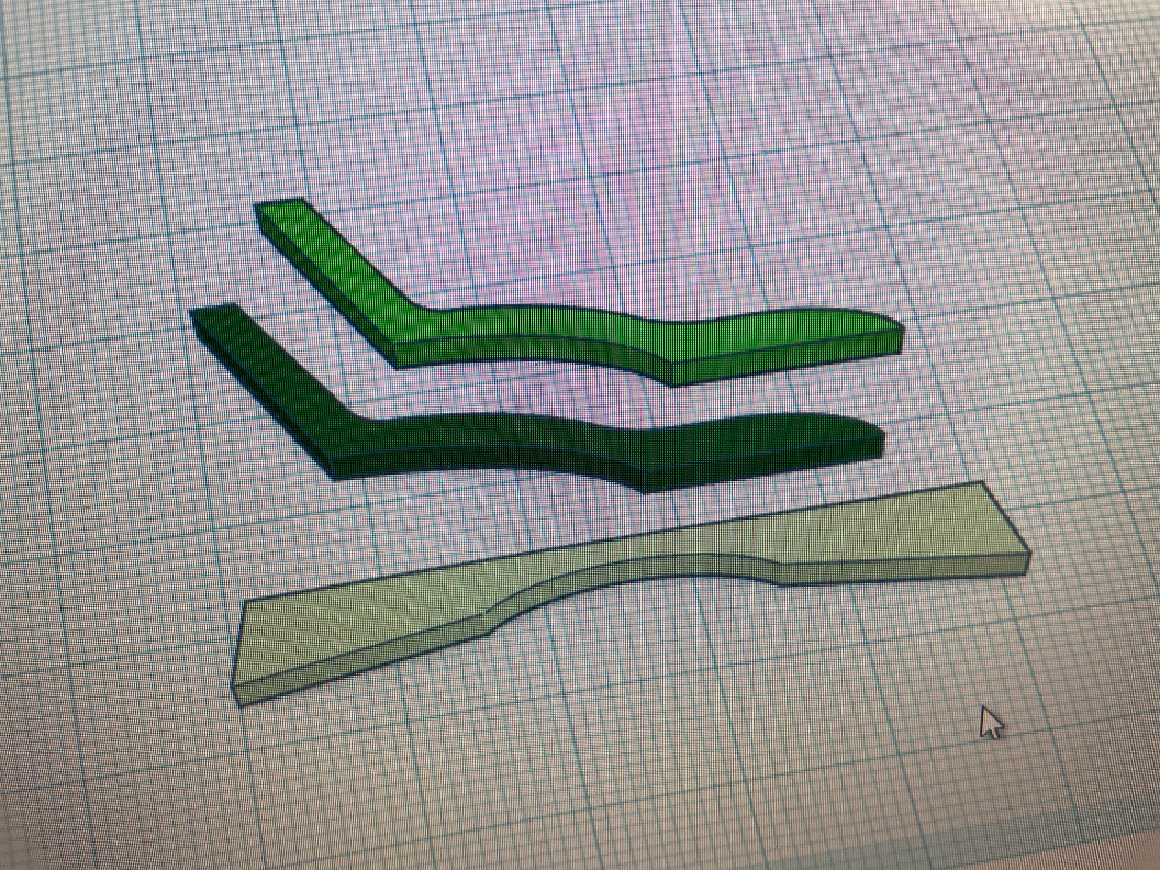
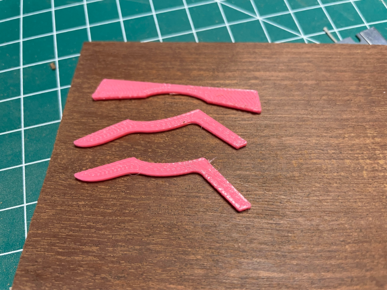
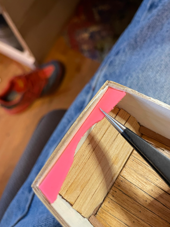
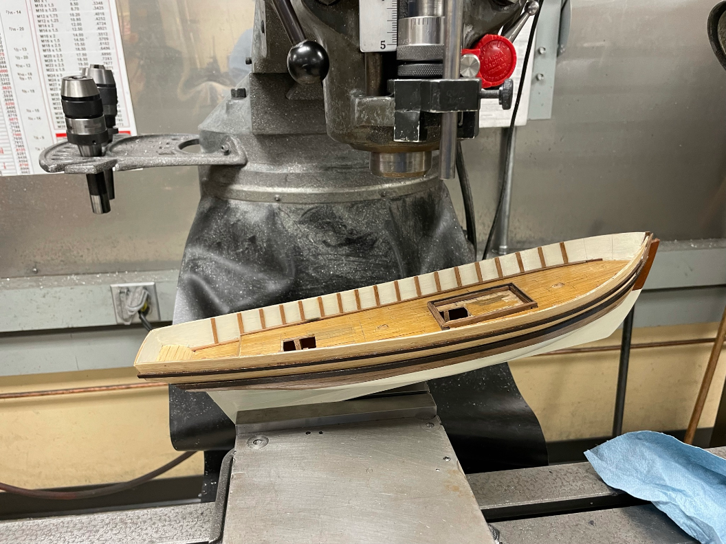
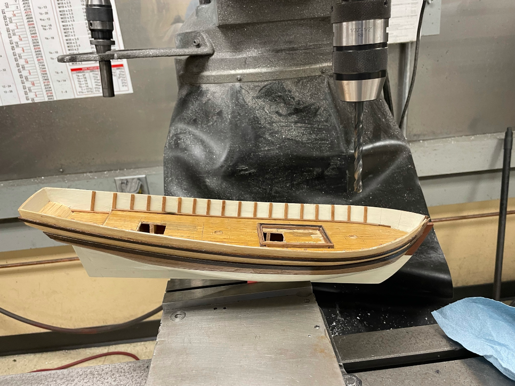
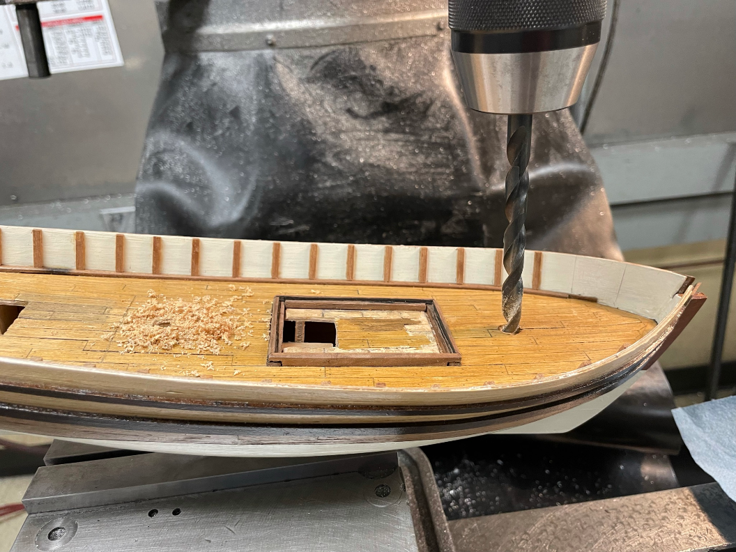
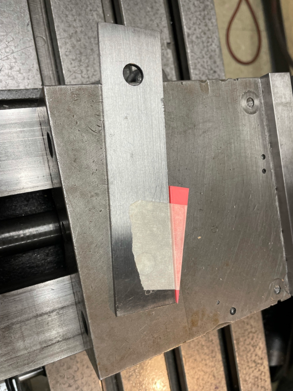
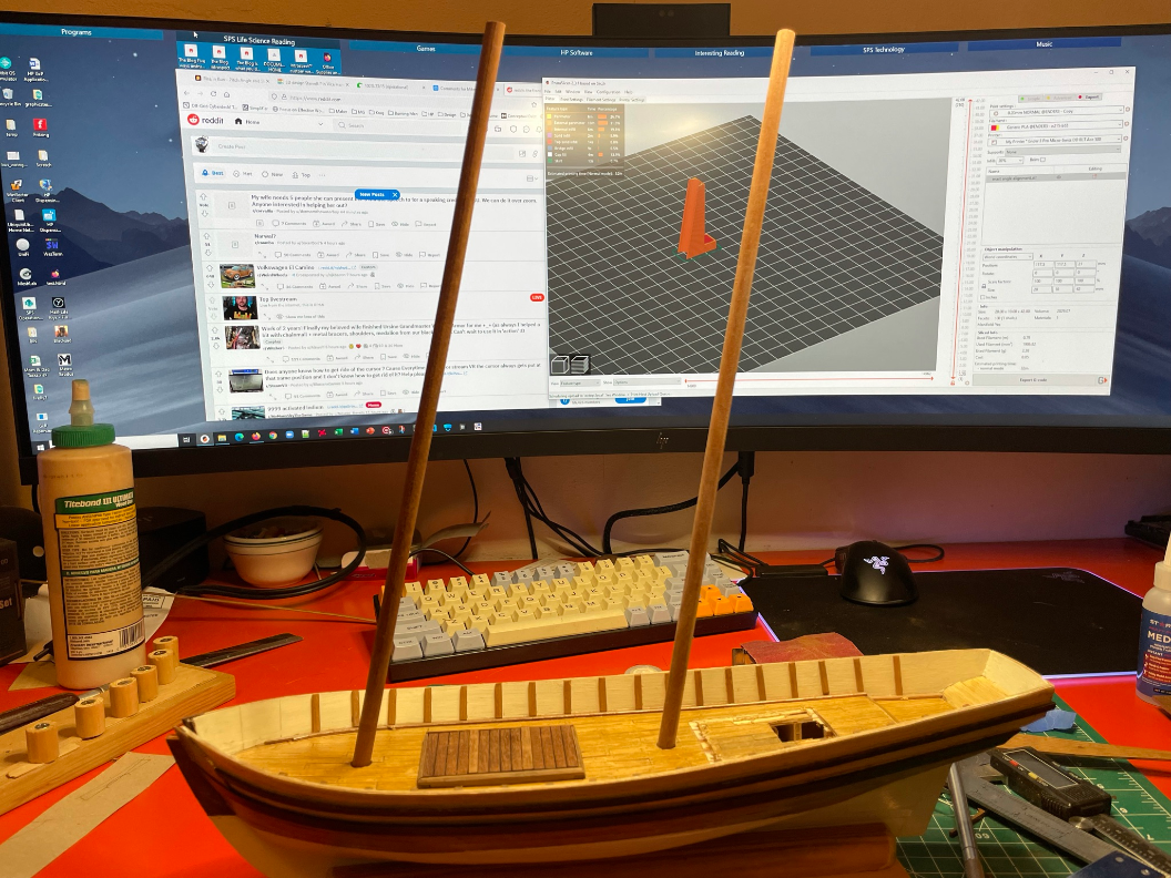
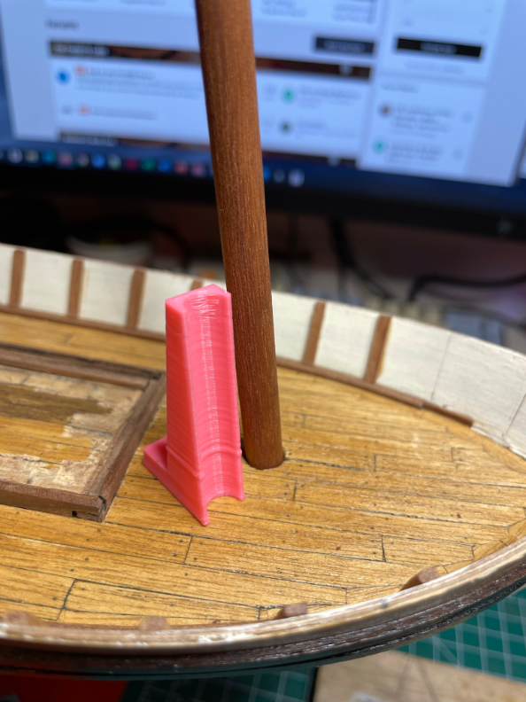
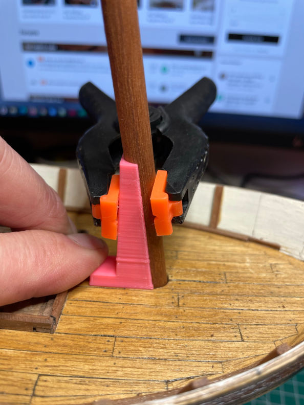
Bunch of random things this weekend. Bulwarks, masts, transom supports, hatch cover, plus some 3D printing and laser cutting of parts. Let's start with making the top rail for the bulwarks. I have a bunch of odd and interesting instrument wood from my father, who used to make instruments. I decided to make the top rail out of some interesting dark wood I have as it's already cut thin for instrument sides. Rather than use the plan for the curvature, I actually traced the edges of the plywood bulwarks with a pencil, then used a knife to cut them out. Here's a shot where you can see the pencil trace. By the way, that little sanding block is something I 3D printed based on a pattern from Thingiverse. It's the same width as sanding strip spools, so it's easy to just tear off 4 inches or so of whatever grit I want and put it on. I'm not quite sure what the wood is. It's not mahogany or walnut. It shows some grain, but seems fairly dense. It sands down to a fine sawdust not unlike mahogany, but doesn't have that smell (nor of walnut). I used the same approach to cut two pieces (port & starboard) for the front as well. I cut a basic scarf joint to join the main rail sections to the front section. I put that on the shelf to dry, and didn't get back to it, as I needed to add bulwark stanchions first. I ended up making a tiny square out of a bit of plywood to mark lines, then glued them on with wood glue... Continuing to jump around a bit, I next decided to make some new stern transom supports. The original stamped out ones were pretty thin, and not very cleanly cut. Also, they didn't quite fit the way the transom came out as I planked it first, then went to add the supports. Lesson learned that I should put the supports in first, then add the planks. To make a good fit, I started out by measuring and making a first pass 3D model of what they should be shaped like. I did the stern belaying pin rack while I was at it, as it also needed to be a bit wider. Here's a photo of the parts (two sizes of supports) in Tinkercad, a free web-based CAD program I use. Once I had the model made, I did a quick 3D printing of the pieces for test fitting. Once I had a good shape that fit well, next step was to export the top view of the CAD files as SVG files, which I could use in a laser cutter available at work. Using another piece of instrument wood, I chose a thin piece of mahogany for the parts. The laser cutter (Glowforge) did a fairly good job, however the 3mm thick mahogany I used didn't cut that well. It burned easily, and it took a number of passes at a lower power, followed by a lot of cleanup of the char to get them cut all the way through. While I was at work to use the laser cutter, I thought I'd also drill the mast holes. We have a big Bridgeport mill in the shop (2 of them actually), so I was able to clamp down the model via the keel, at the right angle. Here are a few pictures of the setup, including the first where after taking the picture I had a brief "oh crap" moment. I didn't drill the angle wrong, but I'm guessing others have done it Here's a picture of how I got the angle right. That's a single parallel that's a bit narrower than the keel, and then a 3D printed angle piece I made that's the right angle for the masts. And here are the masts in place as a dry fit. And a sneak peek at two more things to come... And here Once home I put the transom supports in place (dry fit here). The original model only has the two inner ones, but I made a second set for the outside as well. It just looks better IMO. Still not sure if I'll use them or not. Another thing I did while there is cut some of the same mahogany to make a deck hatch cover. Here's the result, with two in-between strips of a different kind of wood. The mahogany isn't actually cut, but is 3 solid pieces with laser cut scores (about .25mm deep) for the board separations. It's really quite a nice look, as the char gives that nice black caulking look. Here's one other 3D printing thing I did to help with the masts when I do set them. I made a little correctly angled jig with the mast diameter (8mm) cut out along one side. I can then clamp the jig to the mast and keep it nice and straight and aligned if I need to hold it steady.
- 44 replies
-
- 2
-
-
- first build
- Artesian Latina
- (and 1 more)
-
Experiments in Card/Paper Modeling
Tim Holt replied to John Fox III's topic in Card and Paper Models
This is quite interesting! It's nice to see an alternative approach to our usual methods. -
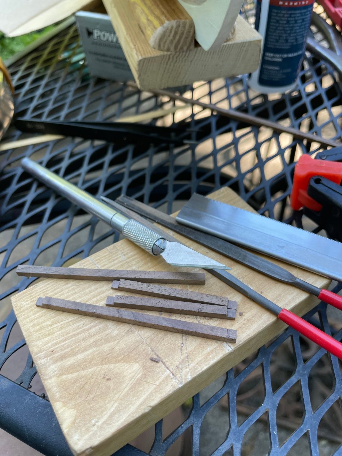
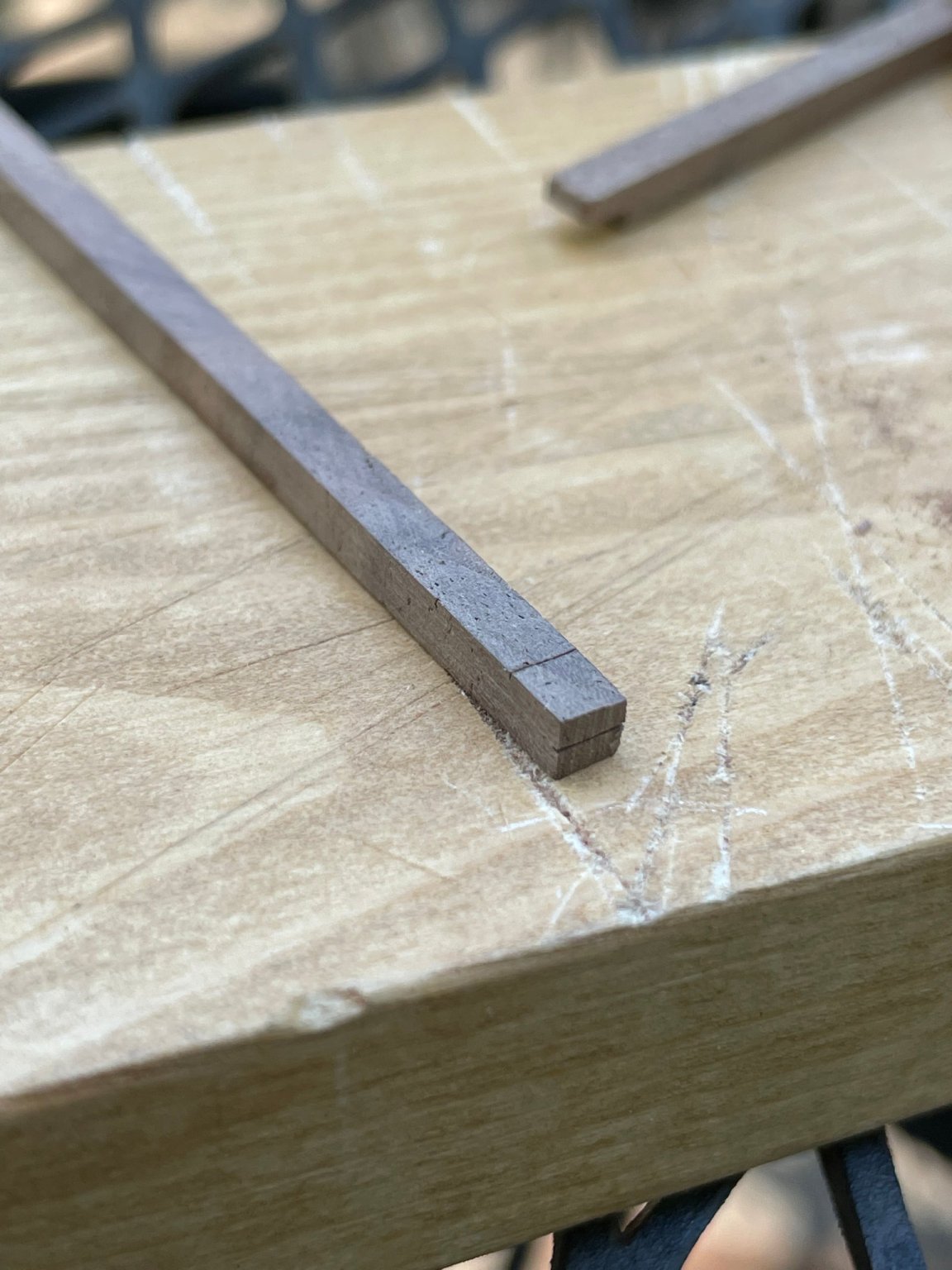
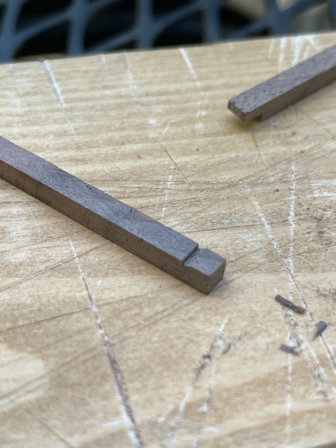
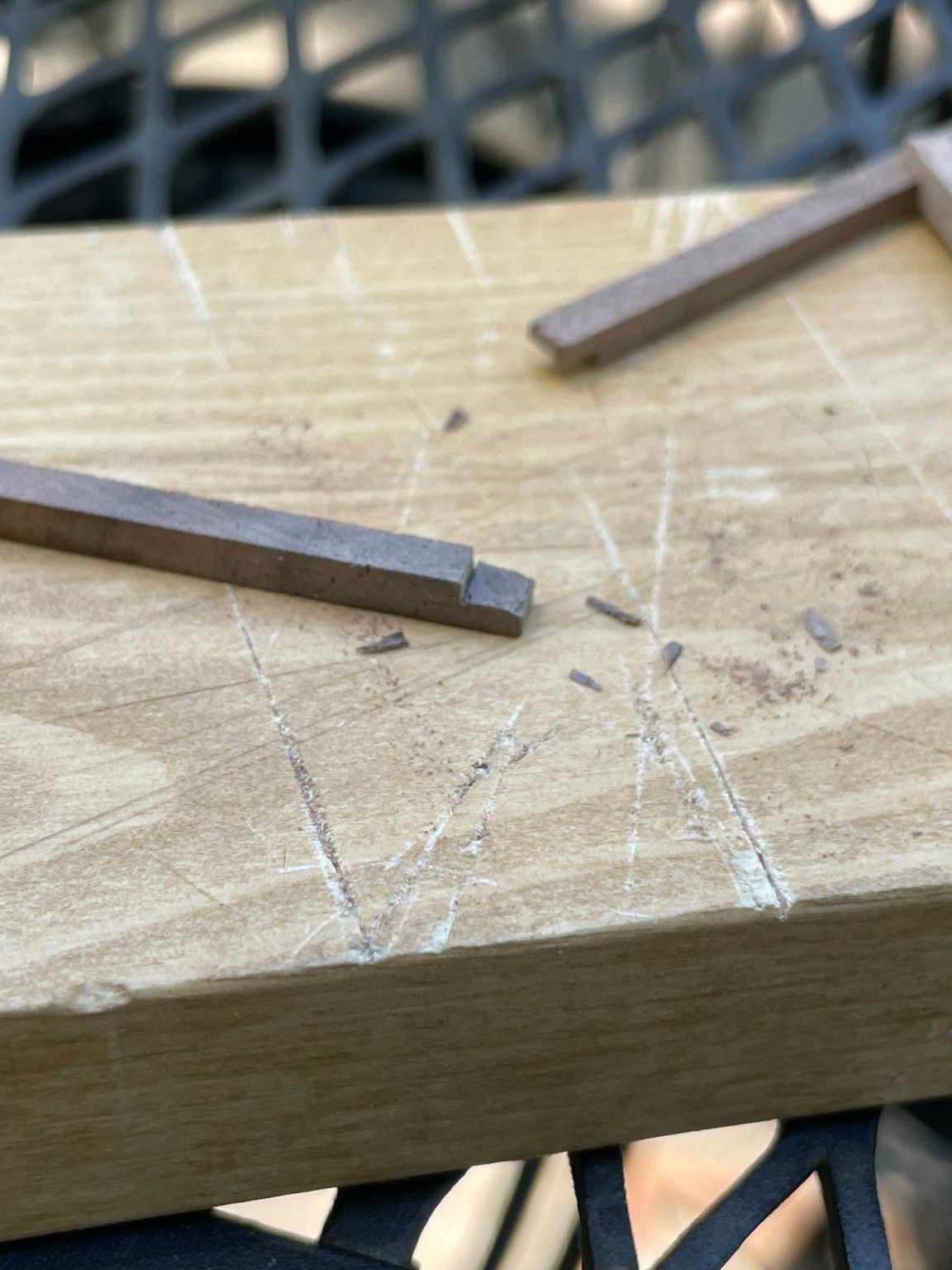
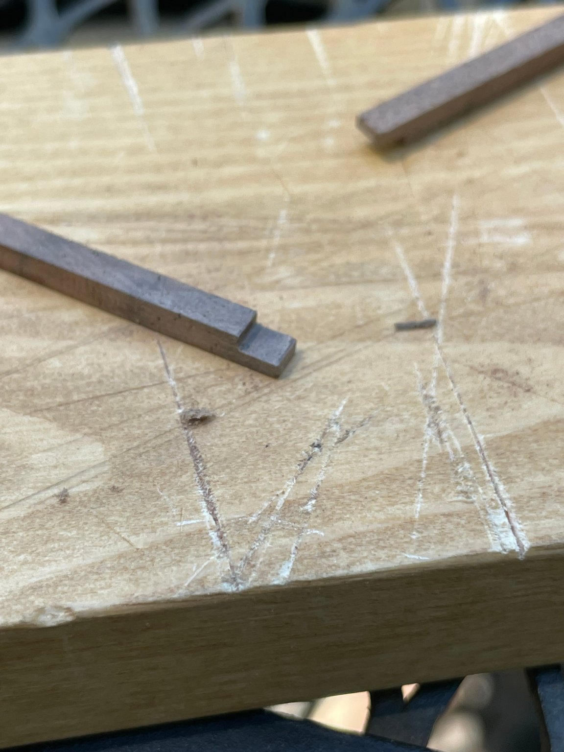
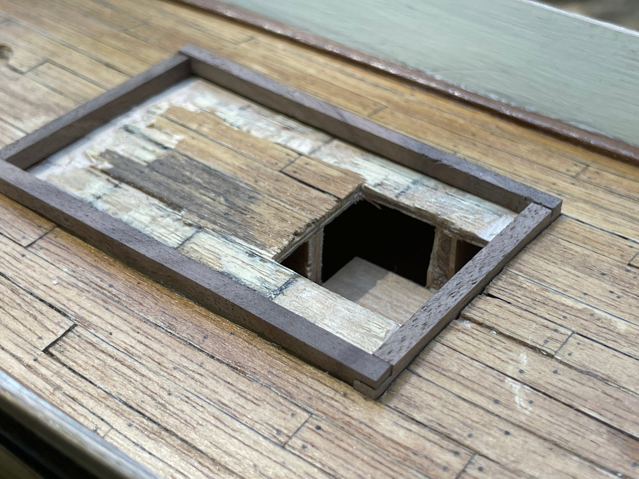
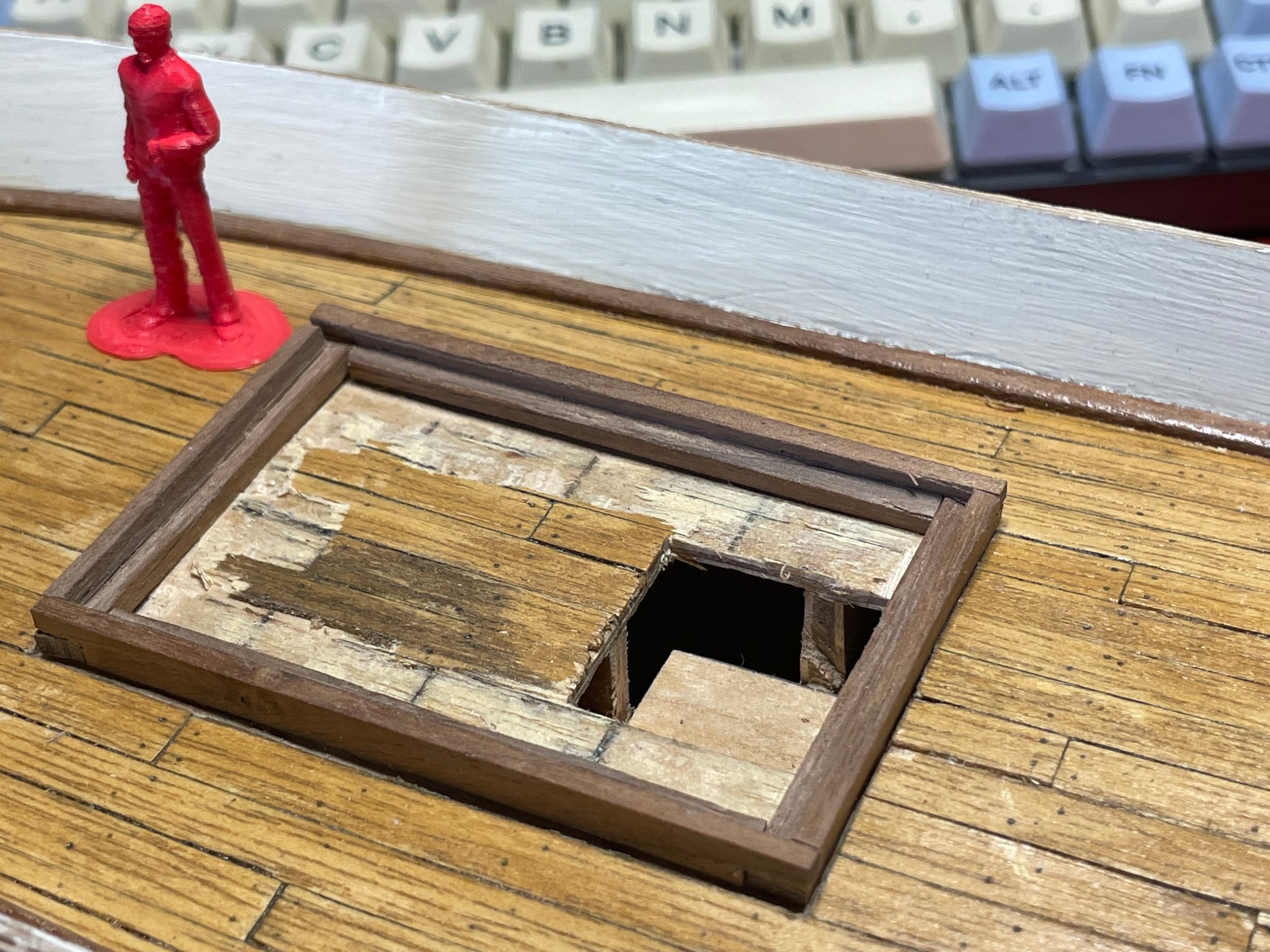
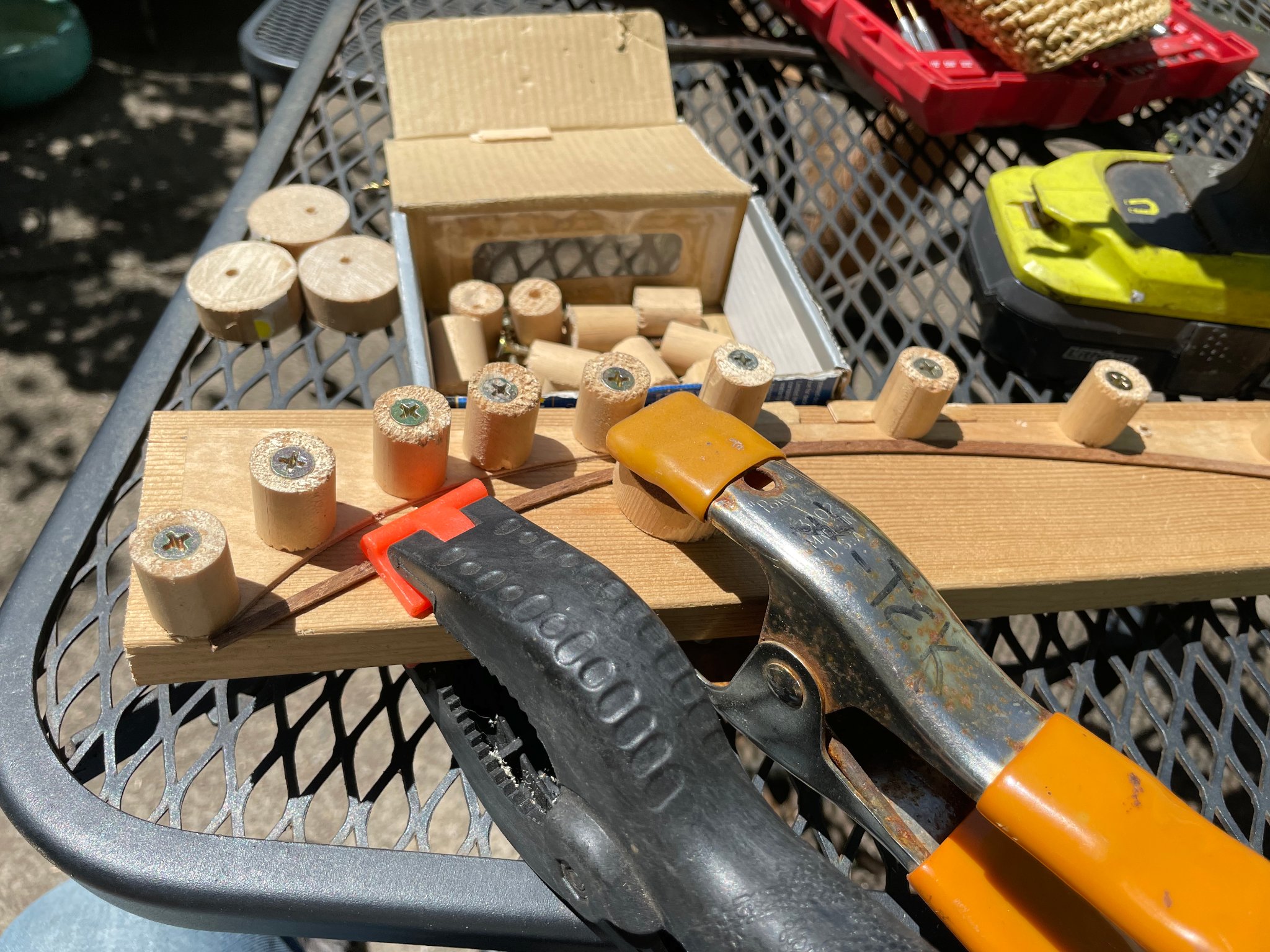
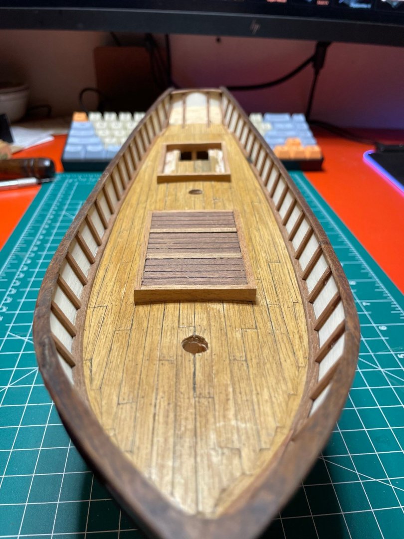
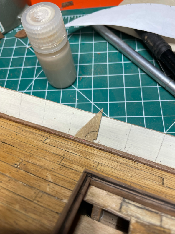
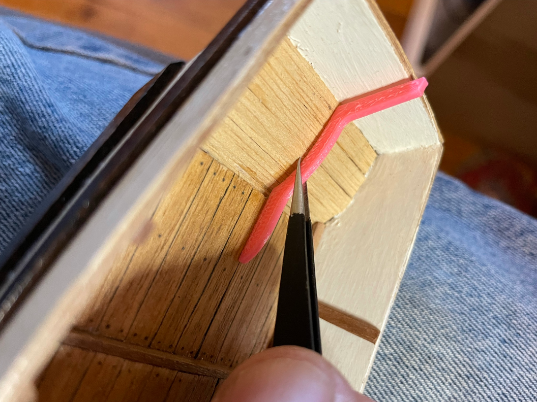
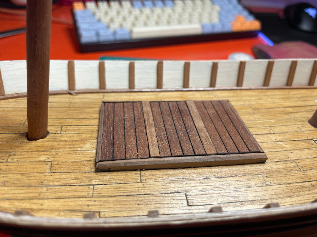
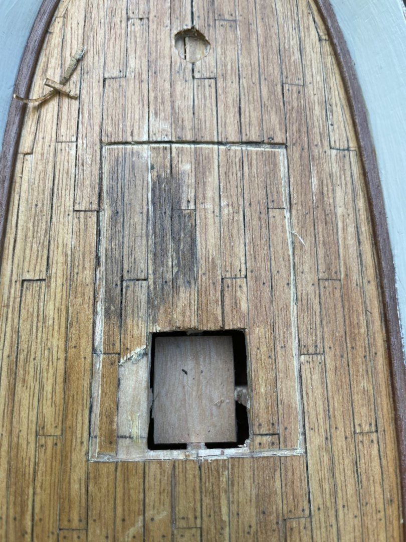
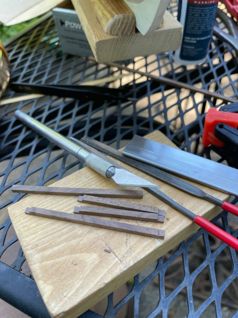
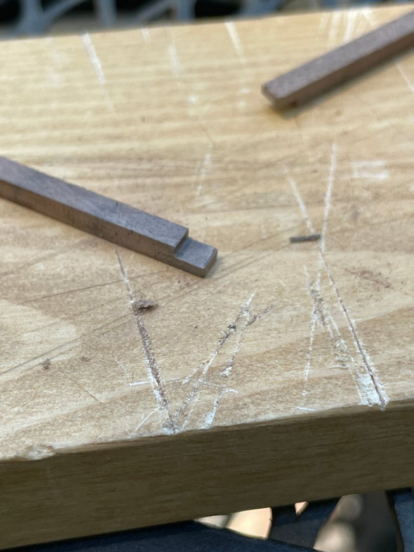
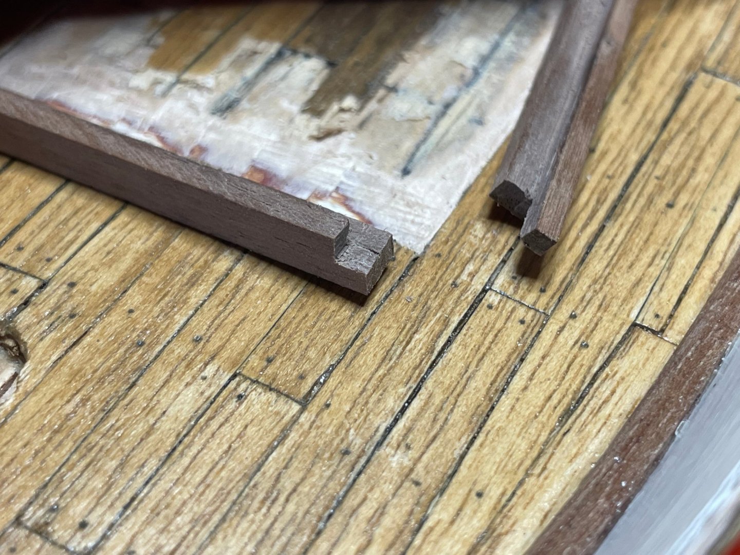
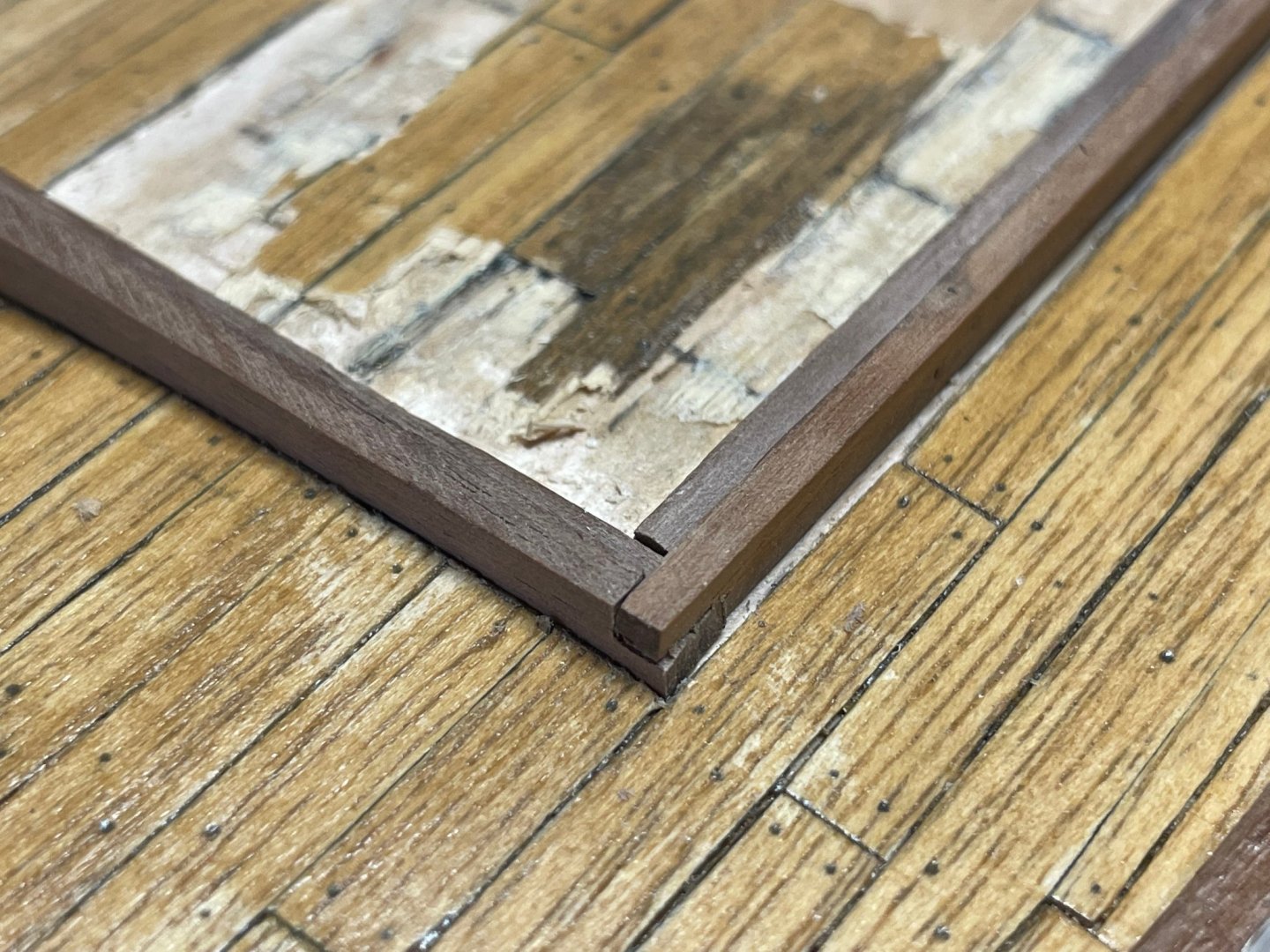
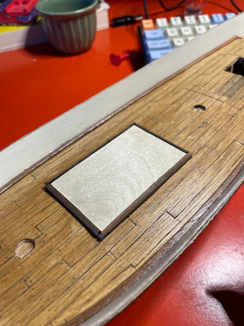
Another fast forward, this time for deck layout. The Swift kit has two cabins, fore and aft. I don't much like how heavy the kit ones look, and didn't really like the look with two. So I decided to replace the forward one with a deck hatch cover, not unlike how the OcCre Polaris looks. I like the look a lot more where the deck structures are not on top of the deck planks, but the deck planks butt directly into the coaming. And one note - it's a LOT easier to lay the deck coaming and other such things down onto the sub-plywood first, THEN apply the planks. Live and learn. I started by using a sharp knife and straight edge to cut out the bounds of the front hatch. Then I started making some 1/8" x 1/8" coaming with little lap joints. To illustrate how I made the lap joints, here's a few step-by-step pictures of one. First, score where the cut will be... Then use a sharp knife to pre-cut just a bit of a notch. Then you can use that notch as a guide for a fine toothed saw. The notch gives you both a clean edge, and good saw blade alignment. Then I cut down the part to be removed with a knife. You have to be super careful with non-straight grain wood like walnut, as it won't just split off a nice flat section. Lastly use a small square file to clean up the joint. Here's a dry fit of the pieces in place. Now about this time, little red scale ship guy showed up and took one look at that tiny coaming and said, "That's not going to do much if the deck is awash - it has to be taller!" So the whole thing got reworked with 1/4" x 1/4" walnut, much to his satisfaction. I ended up hand cutting all the joints and rabbet. I'm starting to see the allure of those tiny table saws. Here are two closeups of the corner joints with the rabbet... Lastly, here's the whole thing with a thin piece of inset plywood that will be the gluing surface for planks covering the hatch. This now brings me up to the present time. Next post in a few days ought to be that hatch finished up.


- 44 replies
-
- 3
-
-
- first build
- Artesian Latina
- (and 1 more)
-
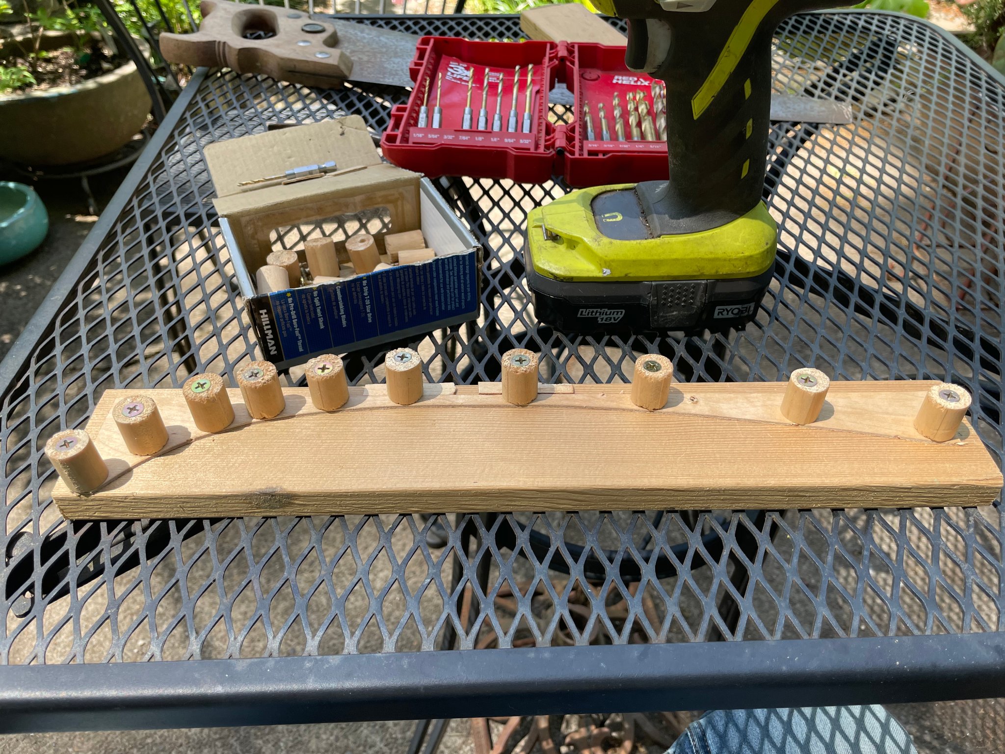
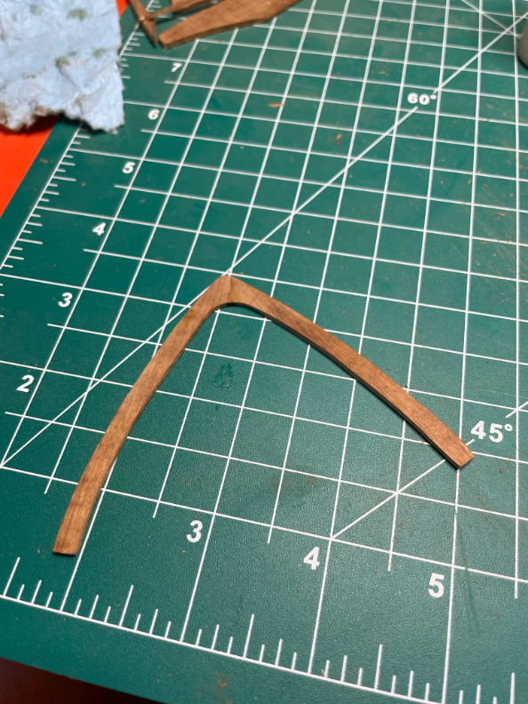
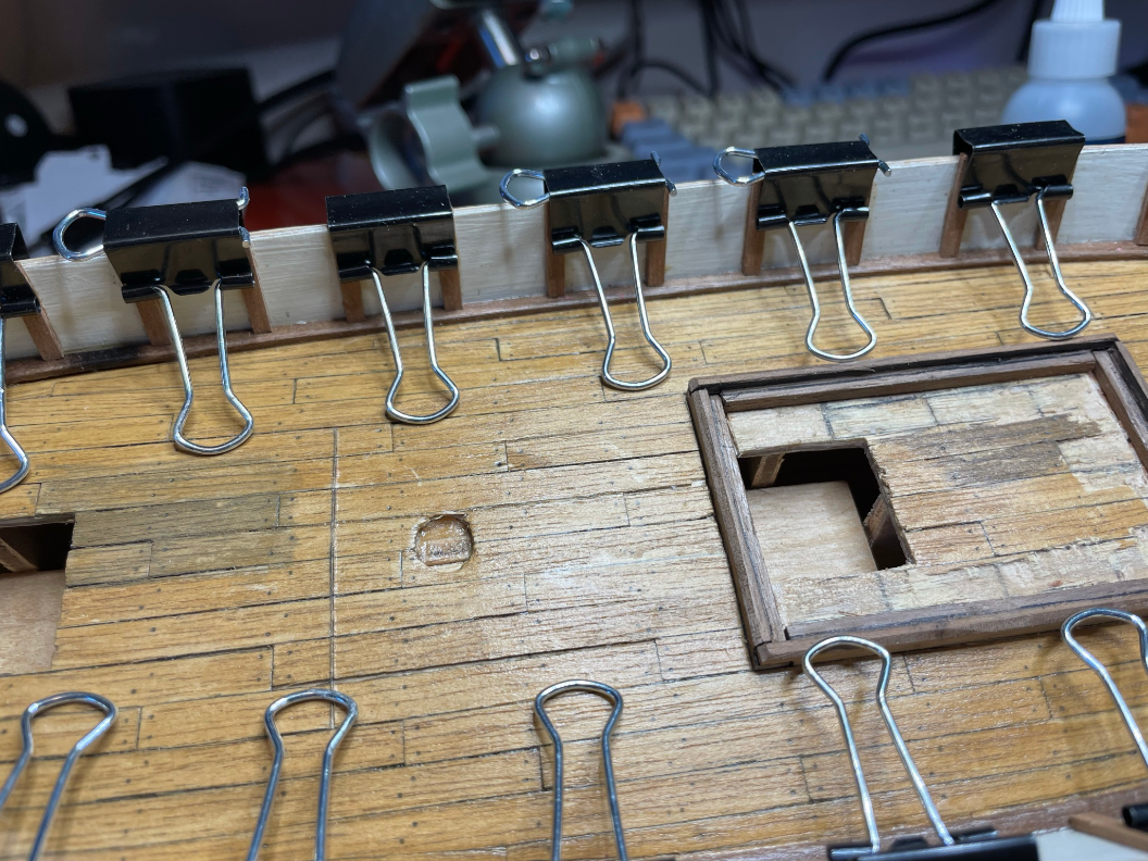
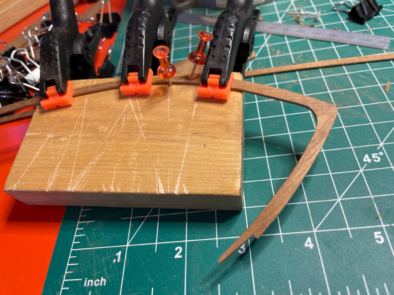
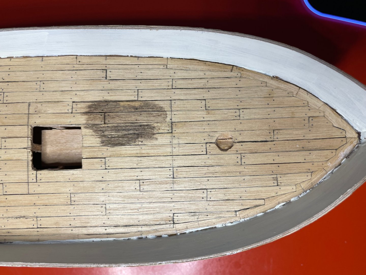
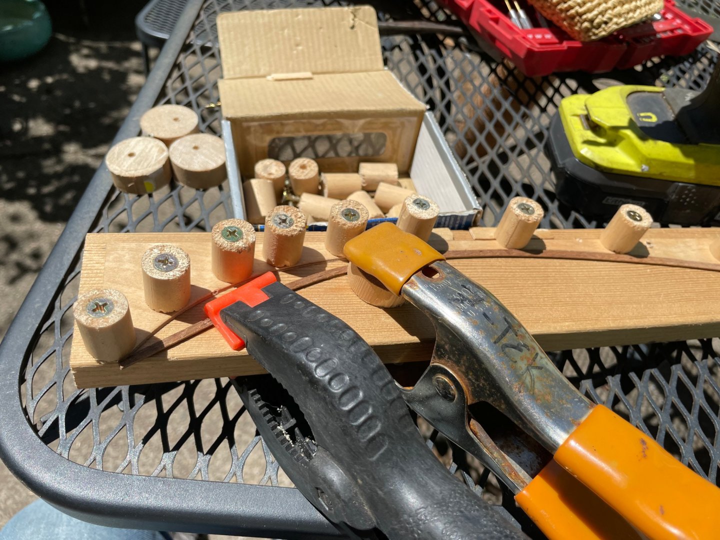
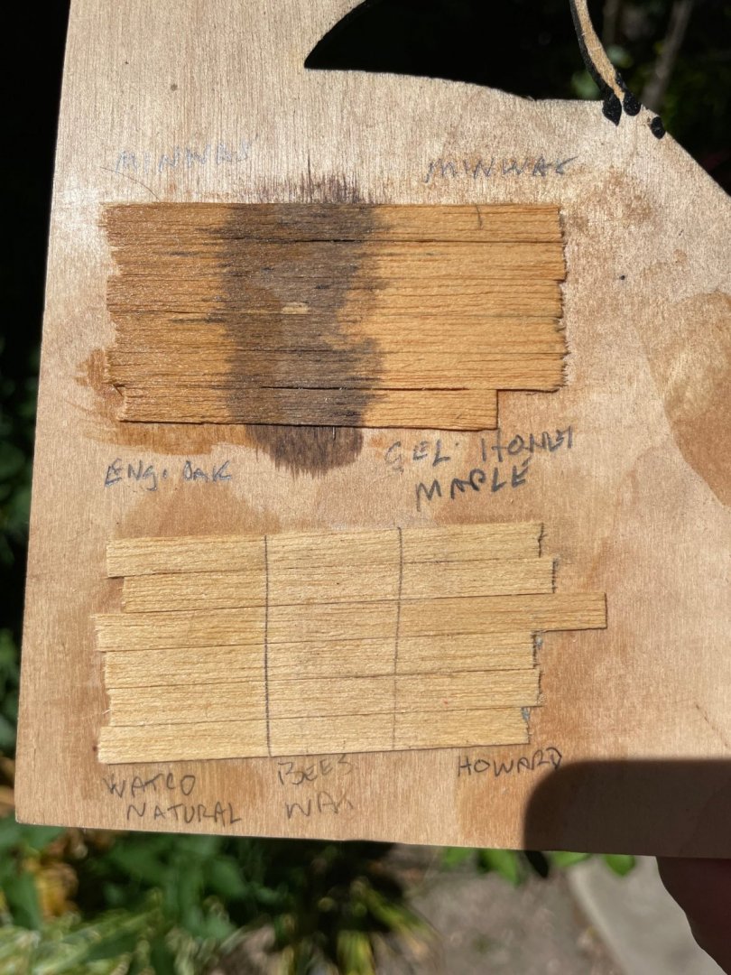
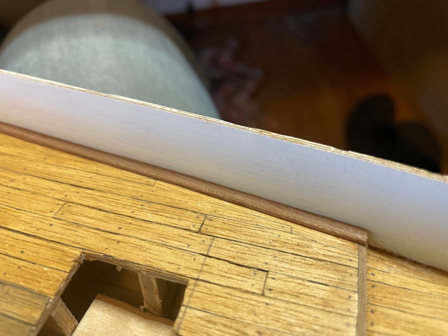
Another fast forward, this time for the deck planking. I cut individual 70mm strips of planking, and used the typical technique of darkening the edges and making small dark points for nails. I used a black coloring pencil for the edges which was much darker than a pencil. It had a tendency to smear a bit, but I kind of like how it dirties up the deck a bit. For the nails, I just used the tip of a mechanical pencil lead. I then scraped the whole surface down smooth with a razor blade before I glued the bulwarks on. I also took a stab at joggling the deck planks, and rather like the look. Not always the tightest joint, but I like the look. Oh you can also see a first course of paint on the inner bulwarks. I decided to not apply planks to them, and just went with a straight white look. And that dark splotch was a little stain test on a place where some deck furniture will go. Too dark for me and I lose a lot of plank seam details. Next up I setup a jig to bend the deck stringers. Here's a few pictures of the setup I built using some dowel sections, as well as the outside waste material from the original plywood sub-deck as a pattern. In the end the stringers still snapped on me in the tight curve section, but that's just an opportunity for a scarf joint if you ask me. While the deck stringers were cooling and drying, I did some finish samples for the deck on a scrap of plywood. For each I applied them, let them dry, then covered with a few layers of satin varnish. Top row L to R: MinWax English Oak, MinWax Special Walnut, MinWax Gel Honey Maple Bottom row L to R: Watco Natural, Beeswax, Howard natural refinishing oil. In the end, the MinWax English Oak won. Here it is with the newly bent stringers in place...

- 44 replies
-
- 2
-
-
- first build
- Artesian Latina
- (and 1 more)
-
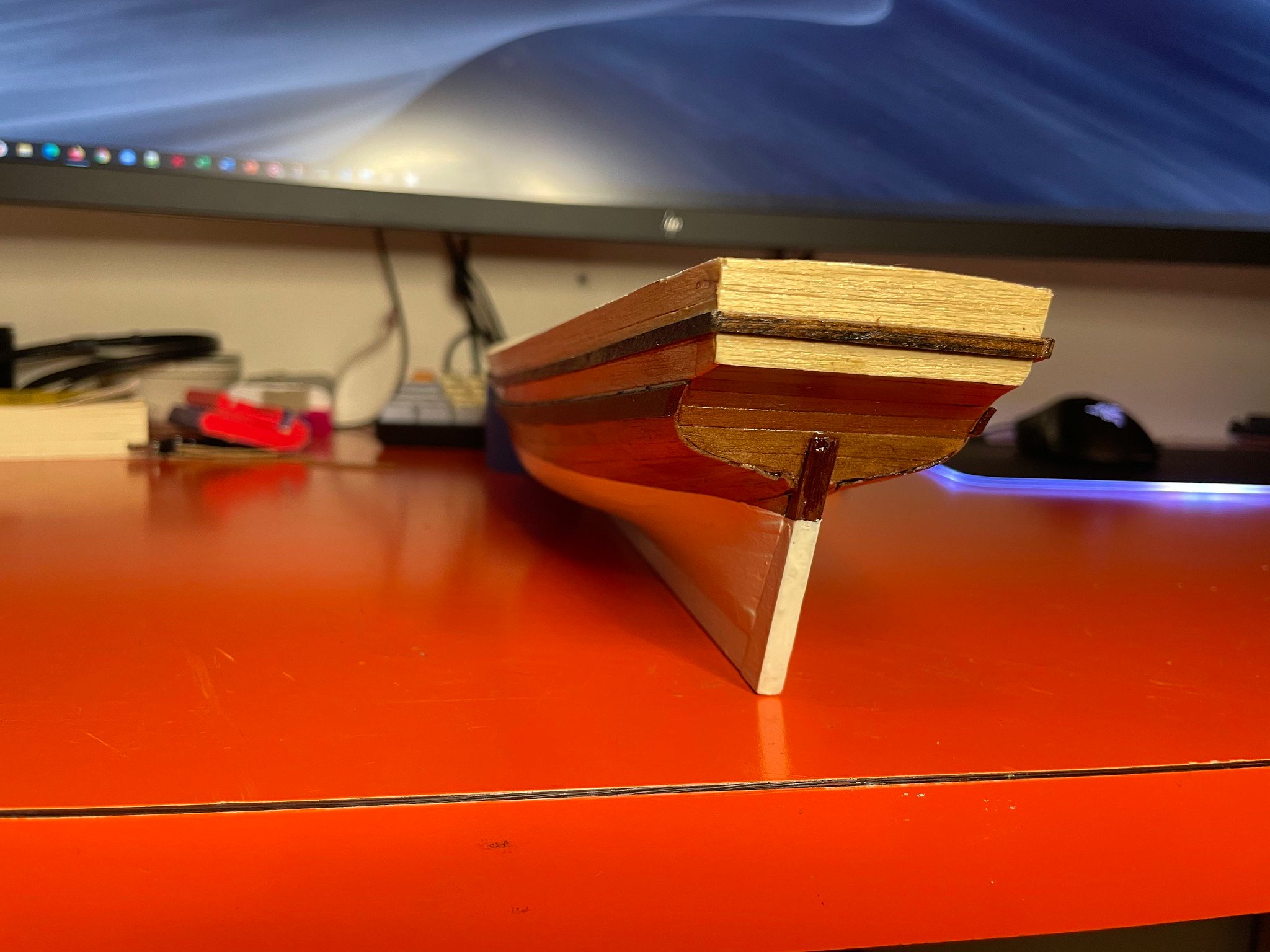
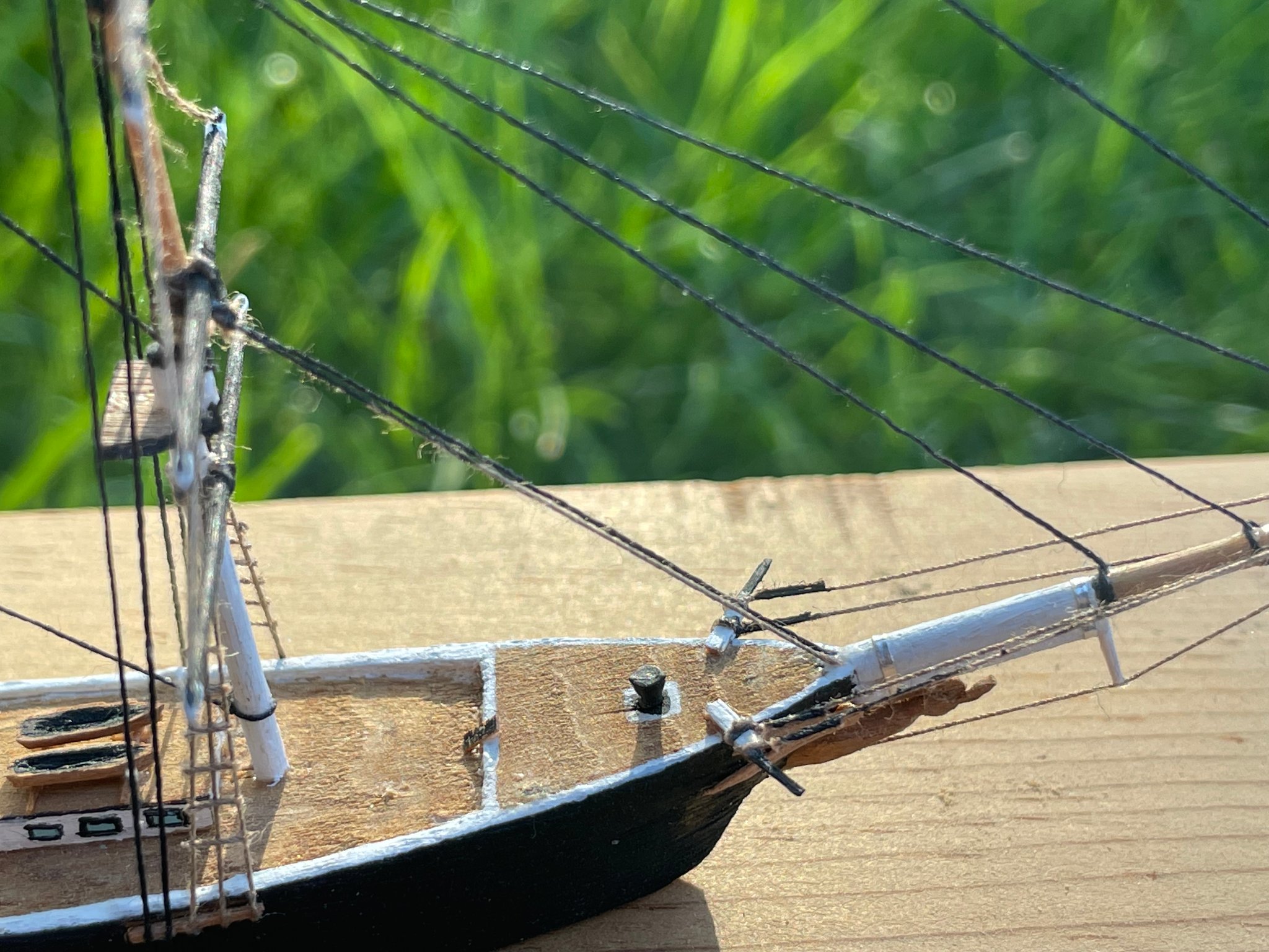
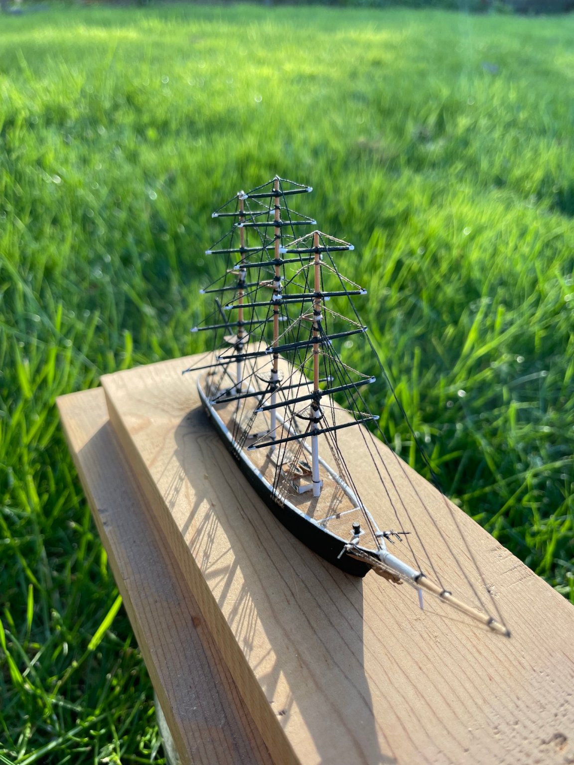
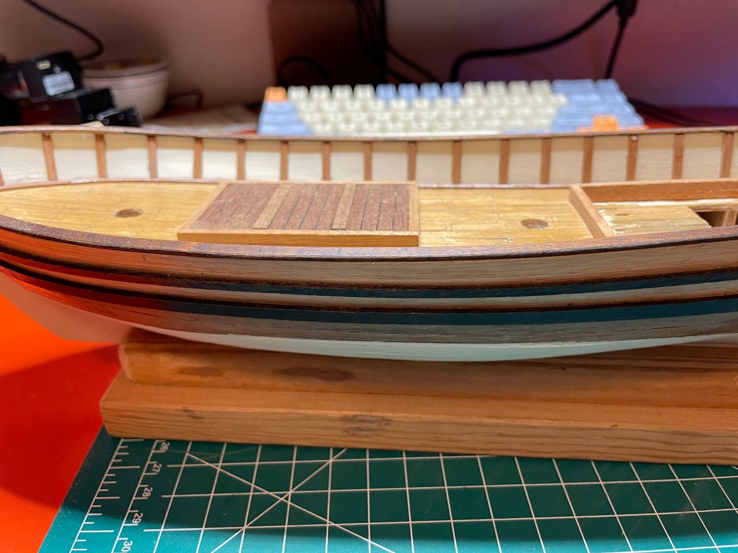
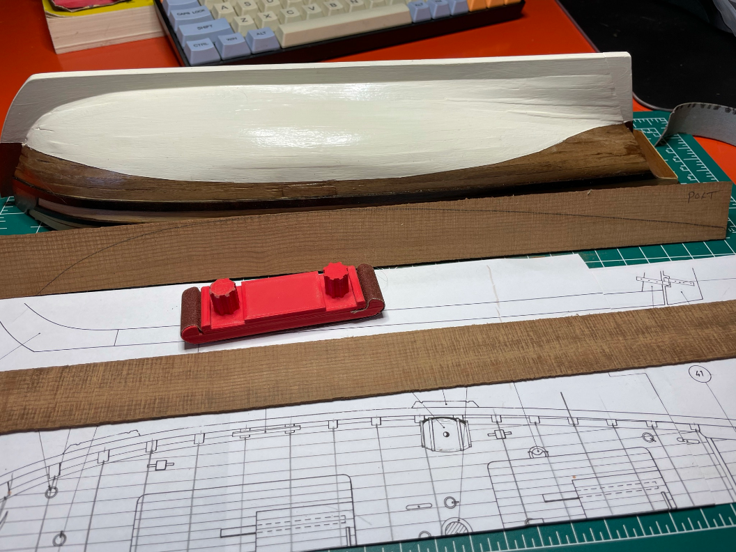
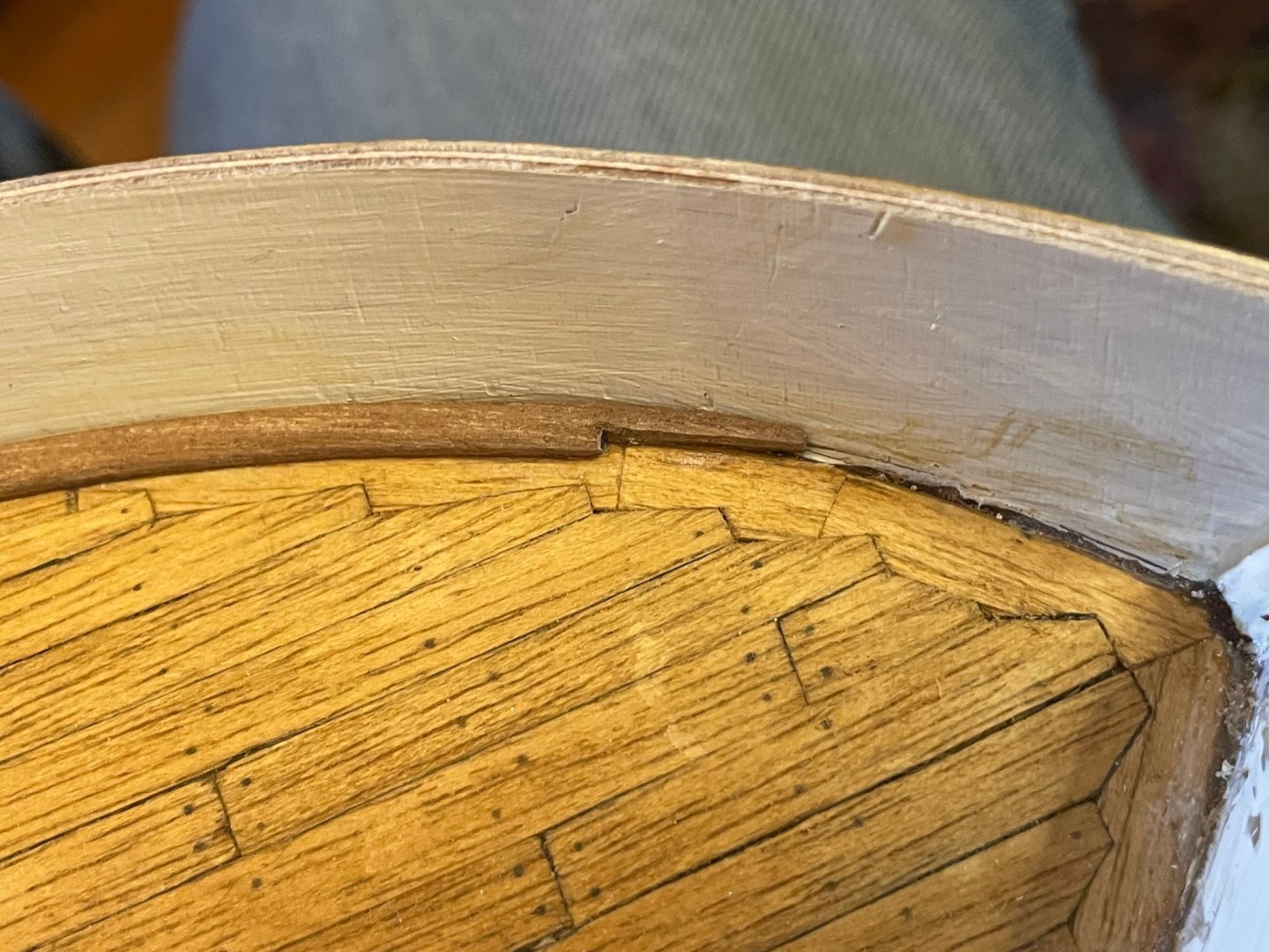
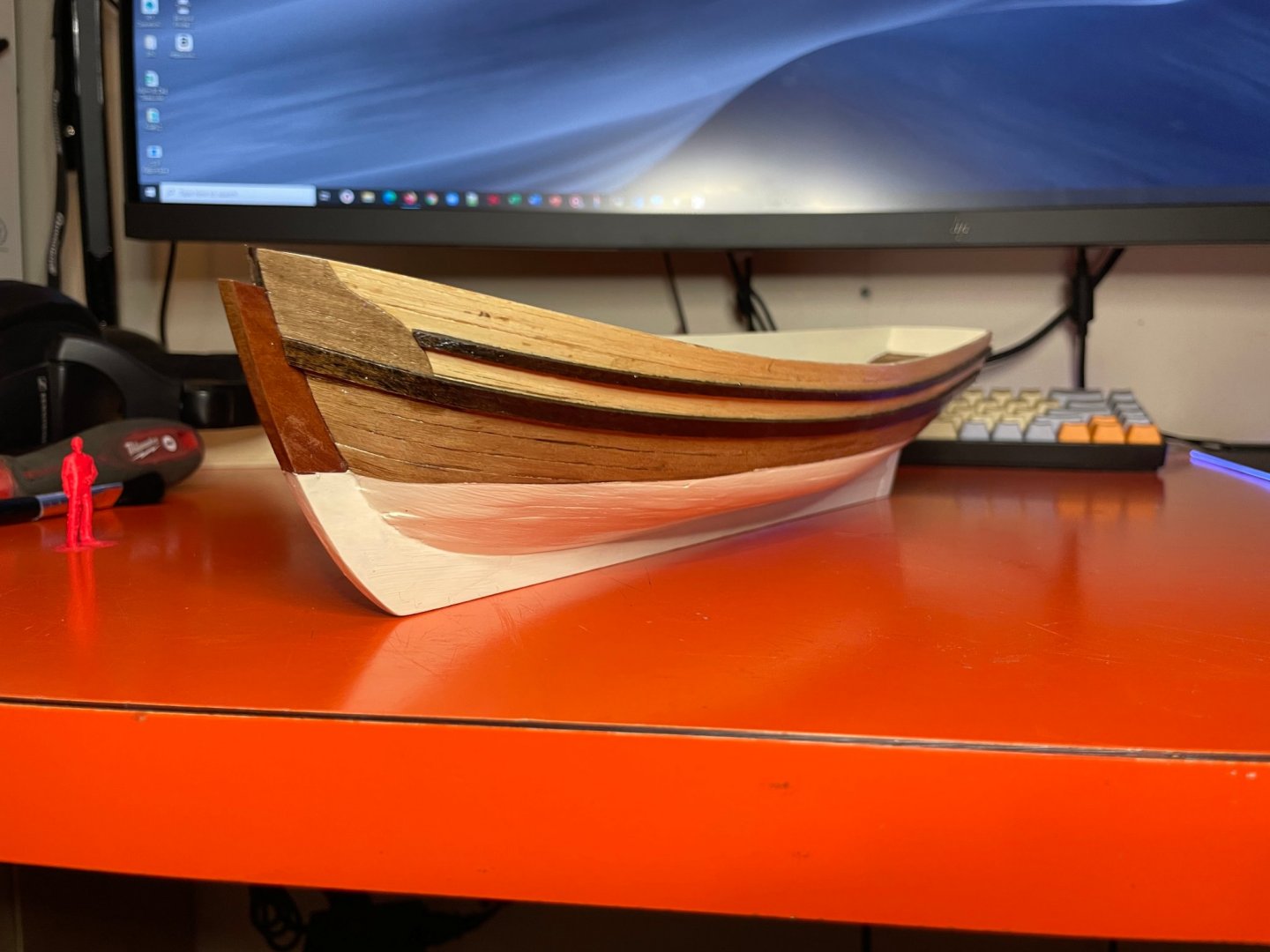
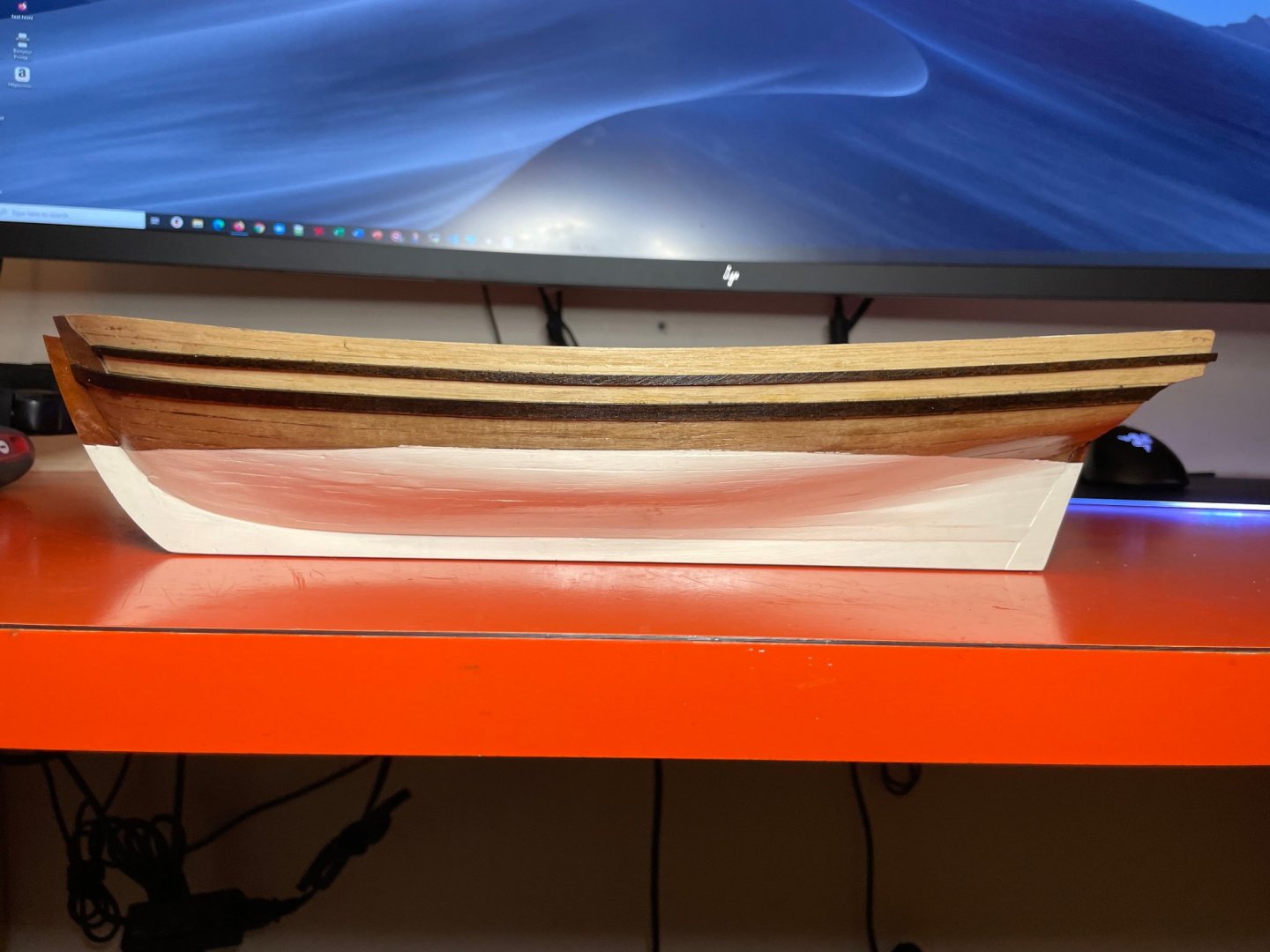
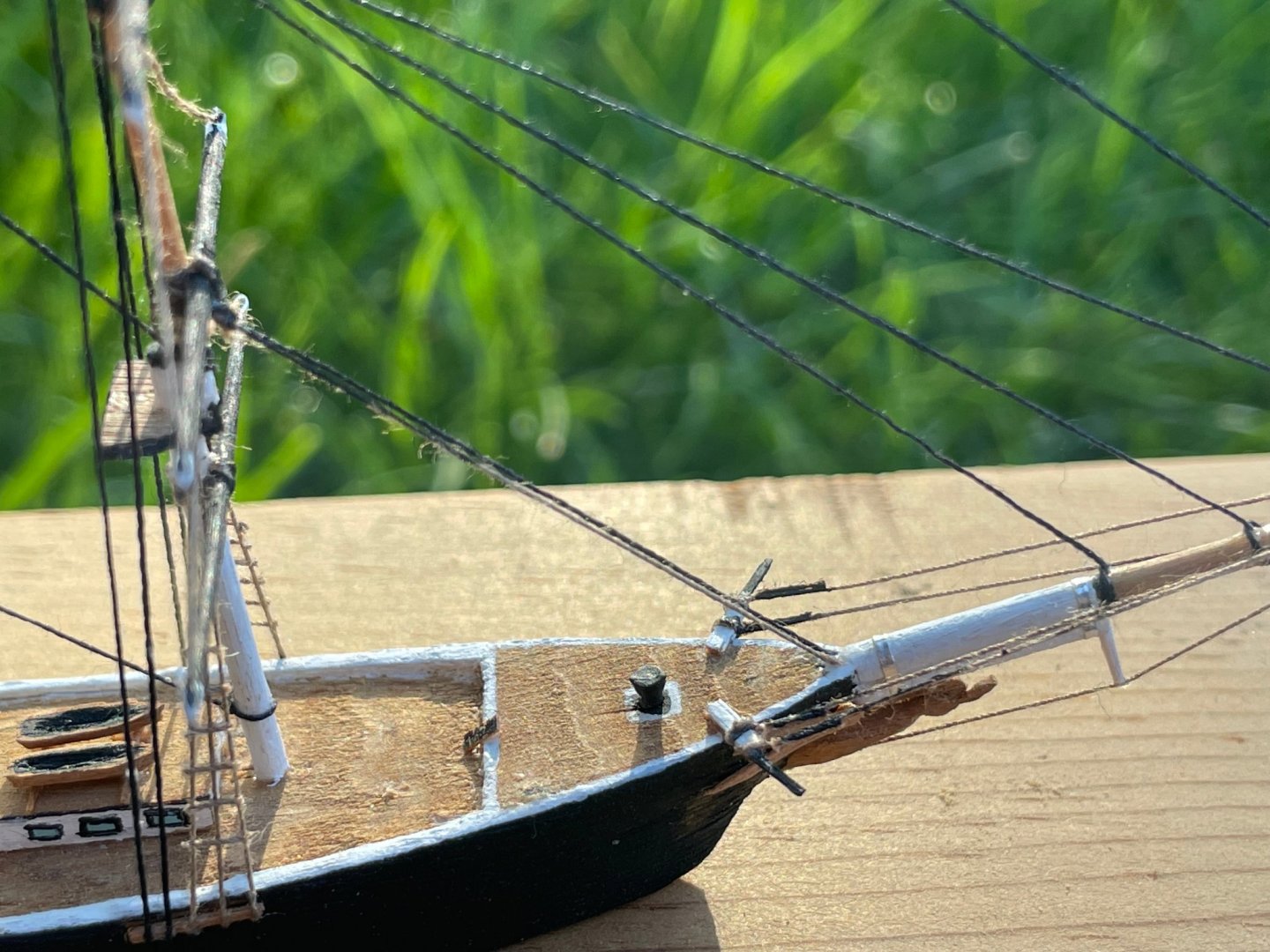
Fast forwards to the hull planking completed. Here are some pictures of how it looks now... I went with a white painted hull, though the second layer of planking wasn't too bad and would have looked OK with just varnish. For paint, I used FolkArt brand 2939CA Vintage White satin acrylic paint, hand brushed. For the fenders, I used MinWax Jacobean 2750 stain, as I quite like the black rail look but prefer the dark stained wood to actual black paint. I then finished everything off with a clear satin varnish (DecoArt DuraClear Satin). Oh yes and in that first picture, you can see "little red ship guy", a small scale figure I 3D printed. He's kind of handy to get a sense of just what the size of things are, and I'm specifically looking forwards to using him as a reference for waist height when placing the tiller. PS I'm still running those OcCre Endeavor build videos in the background - that music is just so calming...

- 44 replies
-
- 2
-
-
- first build
- Artesian Latina
- (and 1 more)
-
Like many, I had an old kit sitting around for years (this one from early/mid 80's) and finally got to it. It's one of 4 models I have, two I bought to build "some day", and two more my father bought but passed on to me when he realized he was running out of "some days" as it were. I didn't start recording all the steps so this is going to soon jump right into the thick of it with some pictures of things I finished up in the last month. I'm also going to artificially break down some of the steps into separate posts just so there's a bit more of a focused subject for each one. Before showing what I started recording with photos, I thought I'd share some of the steps I did "off camera" and what I learned, plus what I used as motivation and learning. First, the plywood bulwarks were a real pain to get right. I quite like the approach that the OcCre kits take, where there is a notch in the bulwarks that fits into a protruding part on the deck plywood so they go just where they should. If I'd seen this before I assembled mine, I'd have been tempted to modify them to use that technique. Second, rather than plank the first layer around the very bow and stern, I built them up with balsa infill. I left the infill proud of the frames such that they had the same surface as the main hull first layer of planks. I got this trick from the YouTube builder Harry Houdini Models. See this video starting about 2:30 for the technique. Third, I quite liked the planking approach that OcCre uses on their models, where they place full width planks without tapers, then fill in with wedges. Their Endurance YouTube series shows it well I think, plus it's got the most pleasing music I've ever heard on any build video! Here's their starting video for planking. Next post will be a fast-forward to the close to finished hull.
- 44 replies
-
- 2
-
-
- first build
- Artesian Latina
- (and 1 more)
-
Hey and that was made in the 80's while working on a ship with a cigar box for my supplies and tools! Now I've got the internet, nice tools, and even a Luxo magnifying lamp on my work bench That and don't have to wedge my knees up under the desk so I stay steady while the world doesn't stay steady. I can definitely see that these old AL kits from the 80's are not so great compared to what there is now. A lot of it with them at this time is obligation - for myself for the many years I've had them, and for the fact my Dad passed them on to me. The Swift is coming along pretty well, and per the earlier suggestion I suppose I should start a build thread on it. I've been redoing a few things with it from scratch, and have been thinking about modifying the deck to match the style of the OcCre Polaris, which looks for all the world like a better Swift.
-
lol @ Adam Savage reference
-
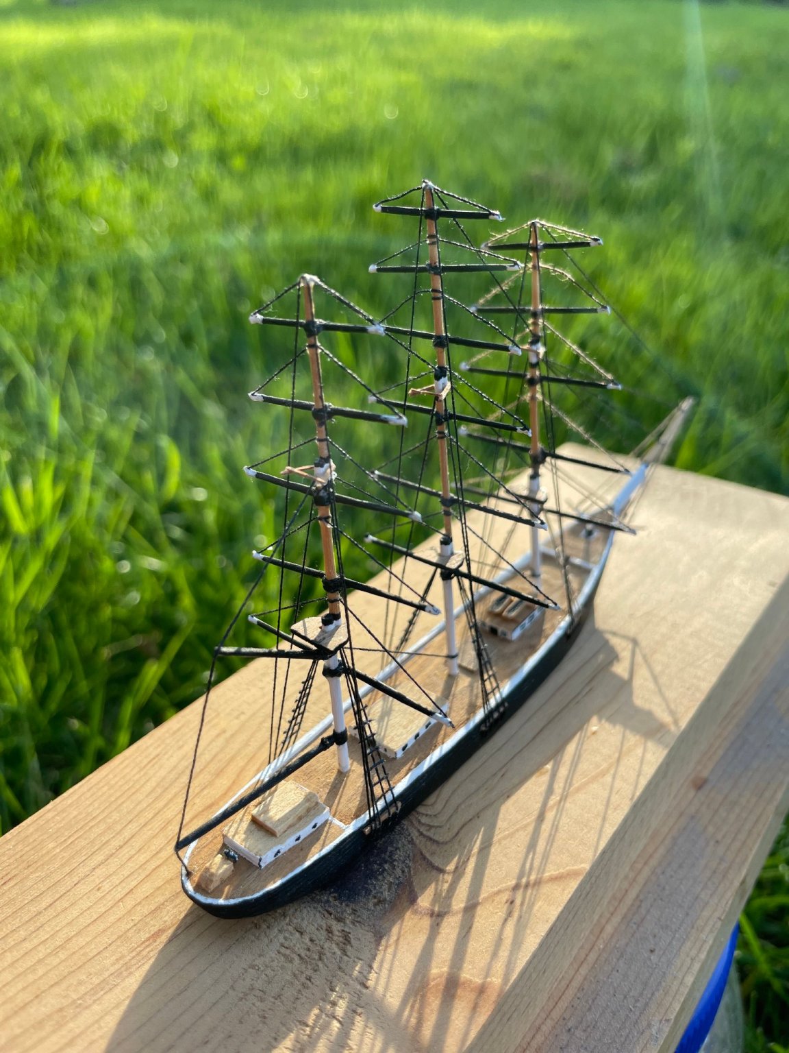
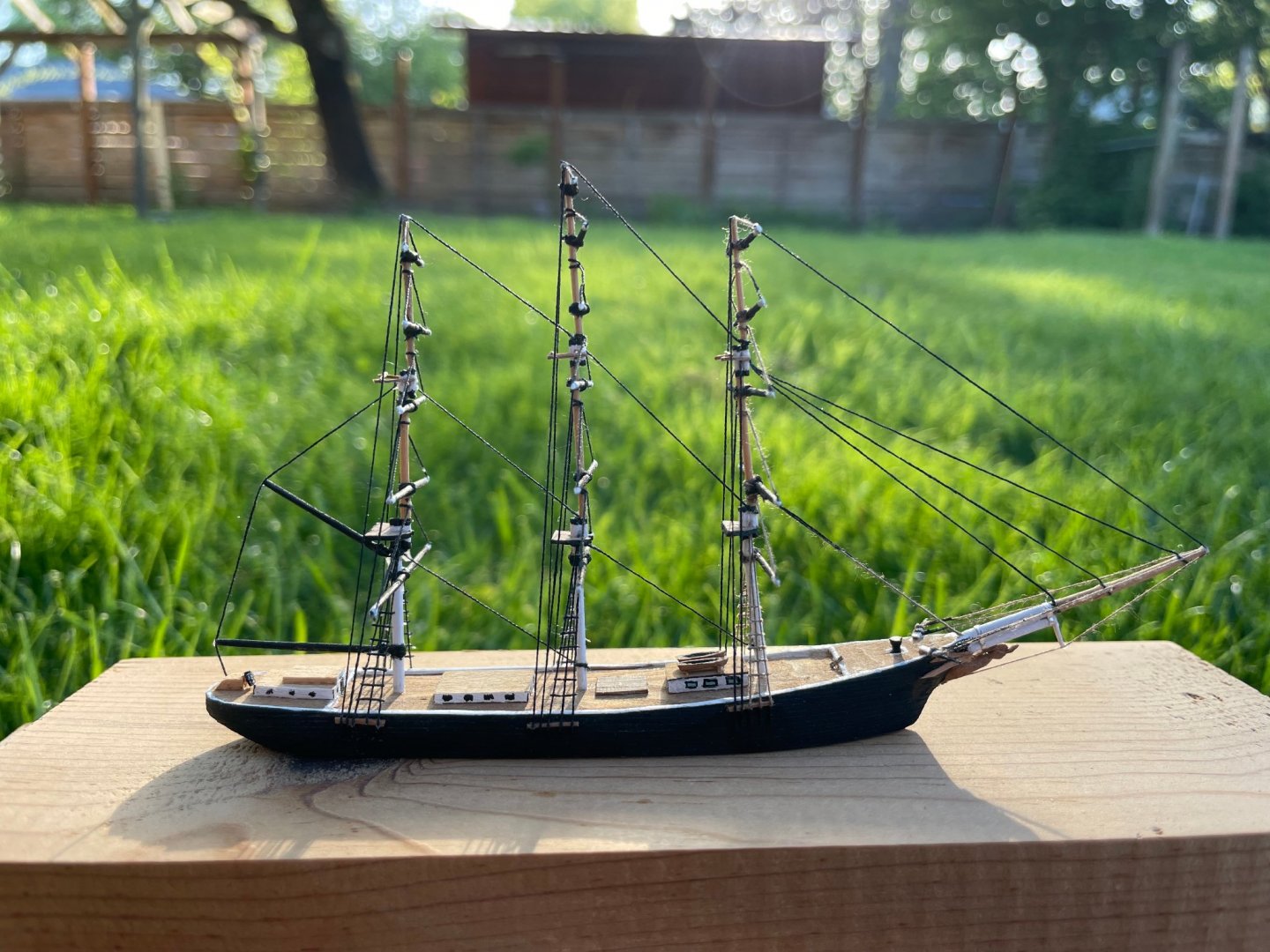
Greetings from (not always) sunny Oregon, USA. I've always been a huge fan of square riggers and sailing, and even worked for many years as a Marine Technician on Oceanographic research ships. As we can be prone to do, kits kept showing up but they never got started. But in this interesting year plus of working from home (software development), I started working on my simplest kit (a very old AL Swift/1805) and actually accomplishing something this time. The hull is all planked and I'm just finishing it (the hull) up before I move on to the "easy stuff". I'm actually getting somewhere, thanks to this forum and the wonderful online videos available now days via YouTube ,etc. Kits in my "attic" right now include an 80's Artesania Latina Swift/1805 (in progress), AL Harvey 1847, AL Falcon, and a "way over my head at the time" Model Shipways Flying Cloud from 1980. I will say that the Flying Cloud plans are just gorgeously drawn compared to what the others are. Oh one of the best things with the kits I got from my Dad is the order receipt where he wrote, "Please send to my work address!!!" as I'm sure in 1980 he didn't want my Mom to know he'd spent $134.00 I did actually do some ship models many years ago when I was at sea. Thread, toothpicks, scrap of pine, some paint, etc. It was easy to pack a modelling kit without taking up a lot of space. These were smaller models, made from scraps of pine, toothpicks, thread, etc. Below are a few pictures of an early one...


- 11 replies
-
- 20
-
-
One comment on this particular paint and color. I picked some up, along with Folkart "Cottage White" and "Wicker White". At first I thought the "Vintage White" was rather yellow looking based on the bottle, but it looks quite good when painted on.
-
Home, bench top laser cutters.
Tim Holt replied to Bill Hudson's topic in Modeling tools and Workshop Equipment
Oh in addition to Inkscape, you can also use the free, web-based Tinkercad (https://www.tinkercad.com/) to create 3D models for both 3D printing and export to SVG cut files for laser cutting. When you export to SVG, it just creates lines from the top view. -
Home, bench top laser cutters.
Tim Holt replied to Bill Hudson's topic in Modeling tools and Workshop Equipment
If you've not seen the Syren Ship Model Company's laser-cut blocks, you should check them out. This is a great example of something a laser cutter is great at, and also of a definitely not one-off part. https://syrenshipmodelcompany.com/internally-strapped-rigging-blocks.php -
Home, bench top laser cutters.
Tim Holt replied to Bill Hudson's topic in Modeling tools and Workshop Equipment
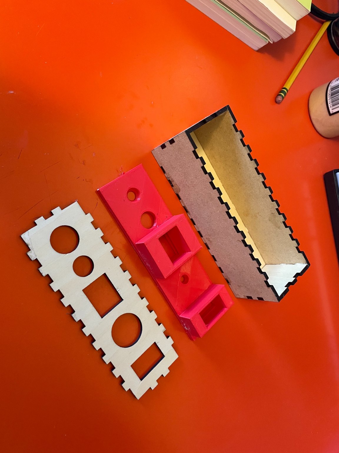
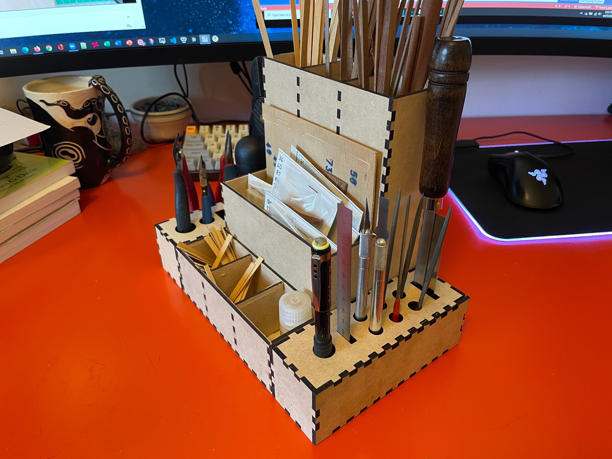
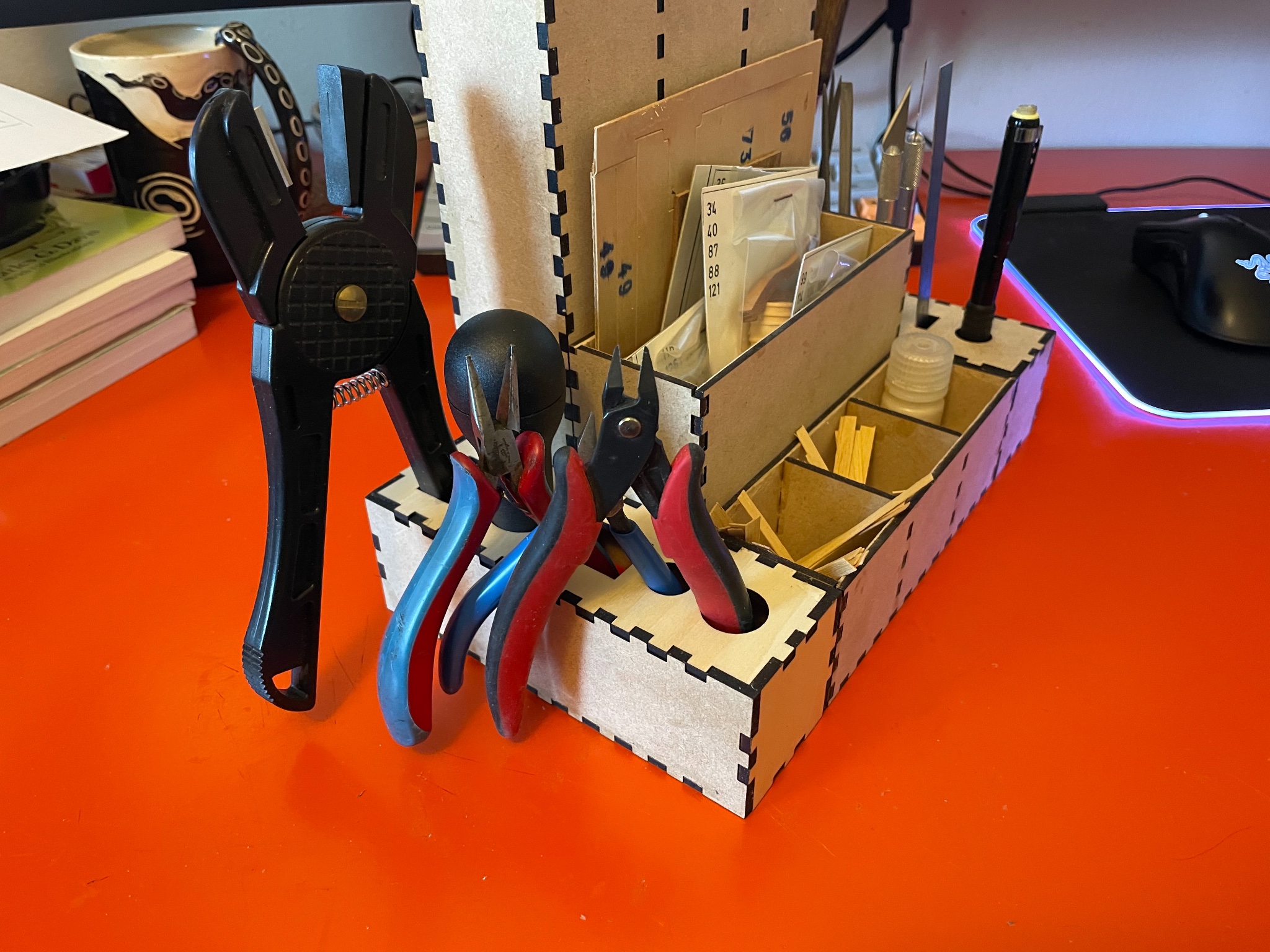
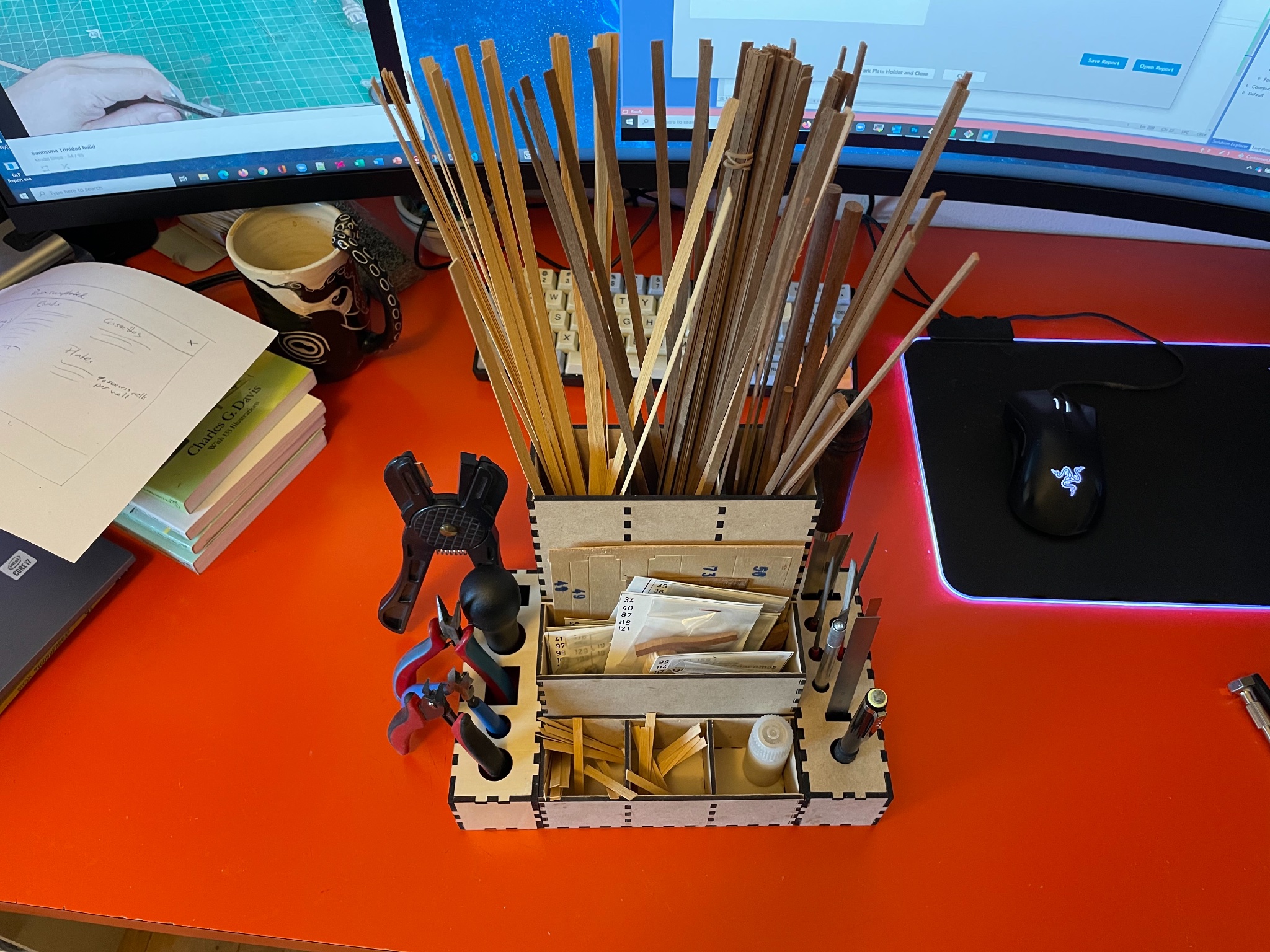
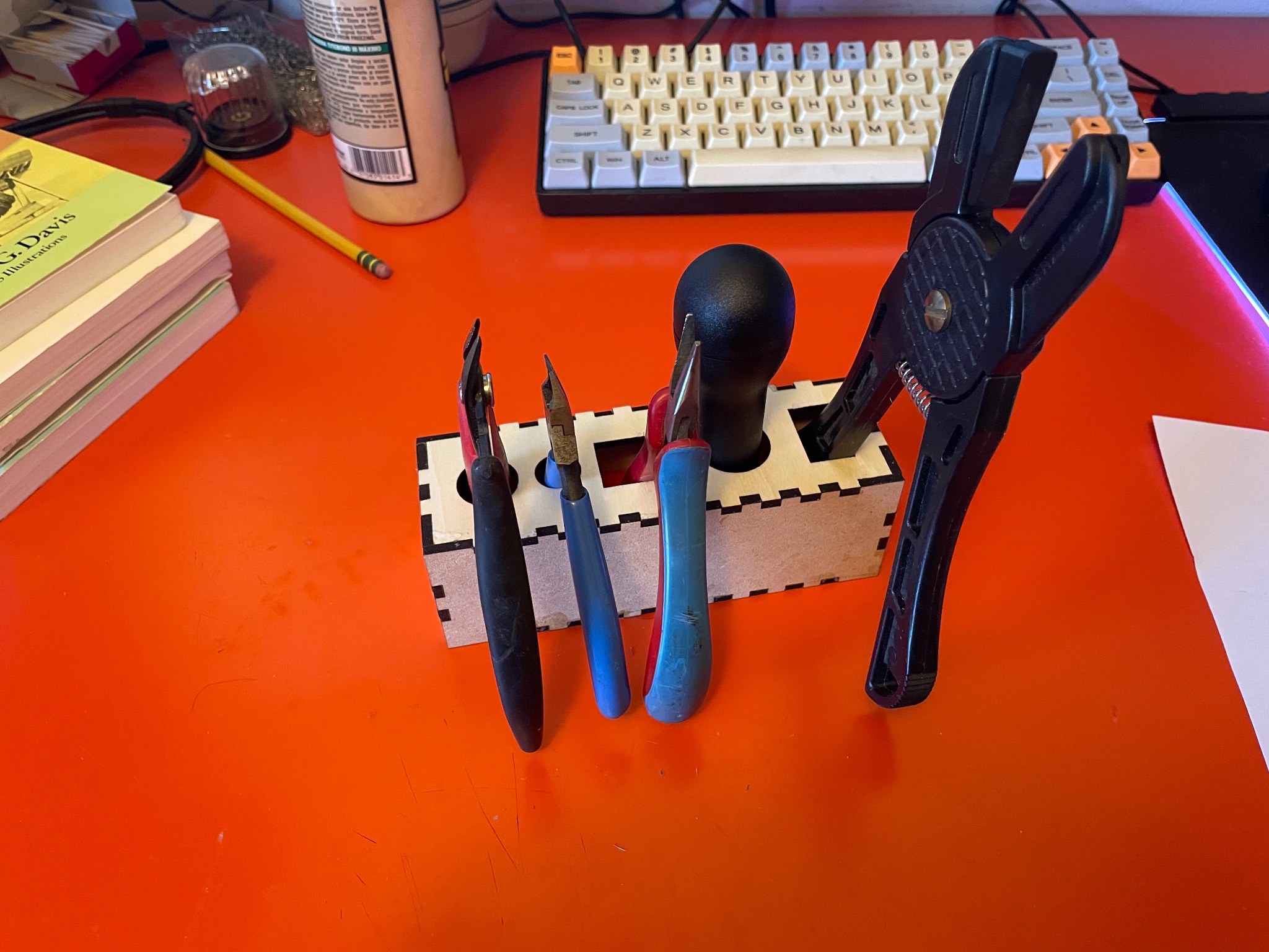
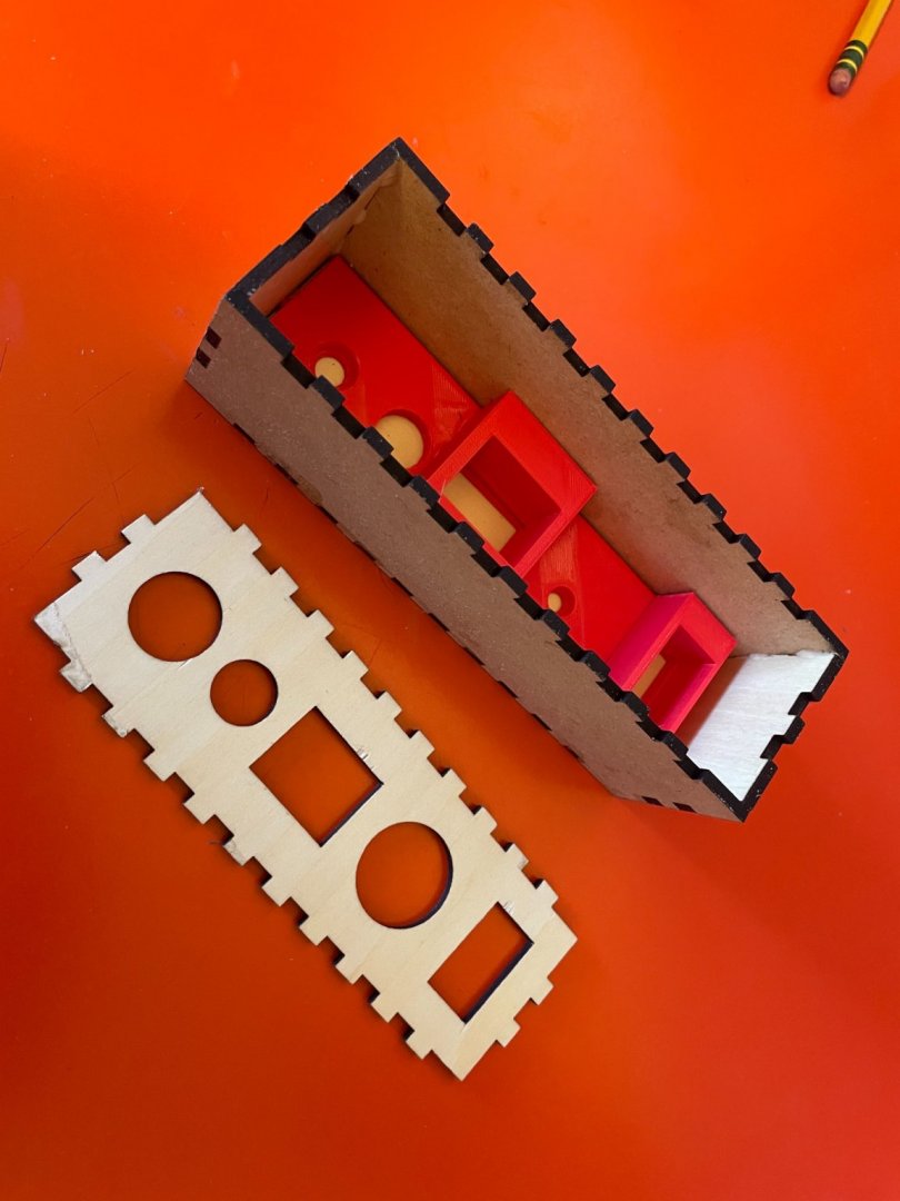
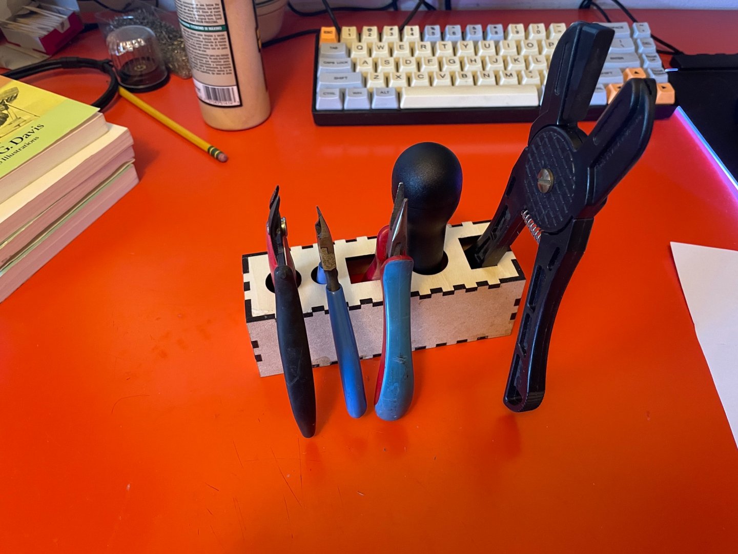
They can be really useful for secondary things. Here are some pictures of a material and tools holder I cut out recently. Some 3D printed inserts to keep the tools in place. it’s basically just a set of separate boxes glued together.


-
Nice to see an old version of this kit being built. I'm currently building one that's got a Copyright 1982 on the box, so probably same as yours. It's a lot simpler (and the instructions pretty slim) so I feel your pain as it were!