HOLIDAY DONATION DRIVE - SUPPORT MSW - DO YOUR PART TO KEEP THIS GREAT FORUM GOING! (Only 13 donations so far - C'mon guys!)
×


Tim Holt
-
Posts
196 -
Joined
-
Last visited
Content Type
Profiles
Forums
Gallery
Events
Everything posted by Tim Holt
-
 Congratulations! That must feel good to put a bow on it and call it done.
 -
Greetings From Beaverton, Oregon
Tim Holt replied to datadiscovery's topic in New member Introductions
Welcome Pete, from middle Oregon. -
One "PS" to the Bluetooth idea. I mentioned that the caliper itself doesn't have much of a battery - just one little 1.5v button cell. But one of the things you can do with that external connector is send power to the caliper. So one idea would be to have a small rechargeable battery as part of the unit, allowing you to run the caliper for much longer without having to replace those little button cells. You could then plug it into a USB-style power connector (or USB cable from computer) to recharge it. I'm about to go on a 2 week vacation and hope to dive back into this when I get back.
-
Agreed, but you need the cable to connect to the semi-proprietary connector on the caliper itself. Plus you have to power the Bluetooth, and the 1.5v battery in the caliper isn't going to cut it, not to mention you still need a computer to read the caliper and send the Bluetooth signal. The whole thing could be taken down to a small add-on you just plug into the top of the caliper, but there's still the matter of powering it. It would need its own rechargeable battery, but it would add bulk. You would in the end still need a USB cable to charge the battery.
-
Feature Suggestion
Tim Holt replied to CDR_Ret's topic in Using the MSW forum - **NO MODELING CONTENT IN THIS SUB-FORUM**
I also did not find the arrows immediately, and for a few weeks was frustrated that I could view one image in a gallery, but not the whole gallery. I didn't even realize you could get to the main album for a picture for a while either. You have to hover your cursor over the popup text and find the unadorned text in the title that is the link to the gallery. One of the current ones is just the word "Tom". It would be nice if the entire text string "From the album: Tom (12 images)" were a link to the album instead. -
Black Pearl by LFNokia - 1/48 - open hull
Tim Holt replied to LFNokia's topic in - Build logs for subjects built 1501 - 1750
I really enjoyed your weathered Santisima Trinidad build series. I imagine you're going to have a lot of weathering on this one too! -
That sub-decking wood is quite interesting. It looks like some of the maple I've pre-inherited from my father which was intended for violin sides.
-
I still need to work out the interaction and interface. Right now I figure these are the basic things I'd like to be able to set... The scale to some value from a list of more common scales. Something like hitting an "up" and "down" button to cycle through a list of common scales. Enter the scale to any number you'd like. A bit more complex, but probably doable. Detect the scale from measurements on existing drawing. I'd personally find this extremely useful when trying to pull dimensions off an illustration or copies of historical plans. What units to convert to (imperial, metric). This really comes down to what you find most convenient to think of in terms of real life. My plan is to mount the screen and Arduino into a small box along with a few buttons for interaction. Alternately a slightly larger touch screen. And also use the screen to display help information to guide the setup of the scale. The advantage of having a little tiny computer drive the whole thing is that you can get rather detailed (in a non-complex way) with information and options. My day job is being the User Experience (UX) and User Interfaces (UI) lead for a bio/life sciences product for a company you usually assume just makes printers, so this is something I want to make easy, clean, and simple. My mantra is that any interface that requires a manual or training video is too complex, unless you're working with a very complex task to start with. And even then, you look for ways to make it simple. Working out scale dimensions for a model is not a complex task - laborious yes, but not complex.
-
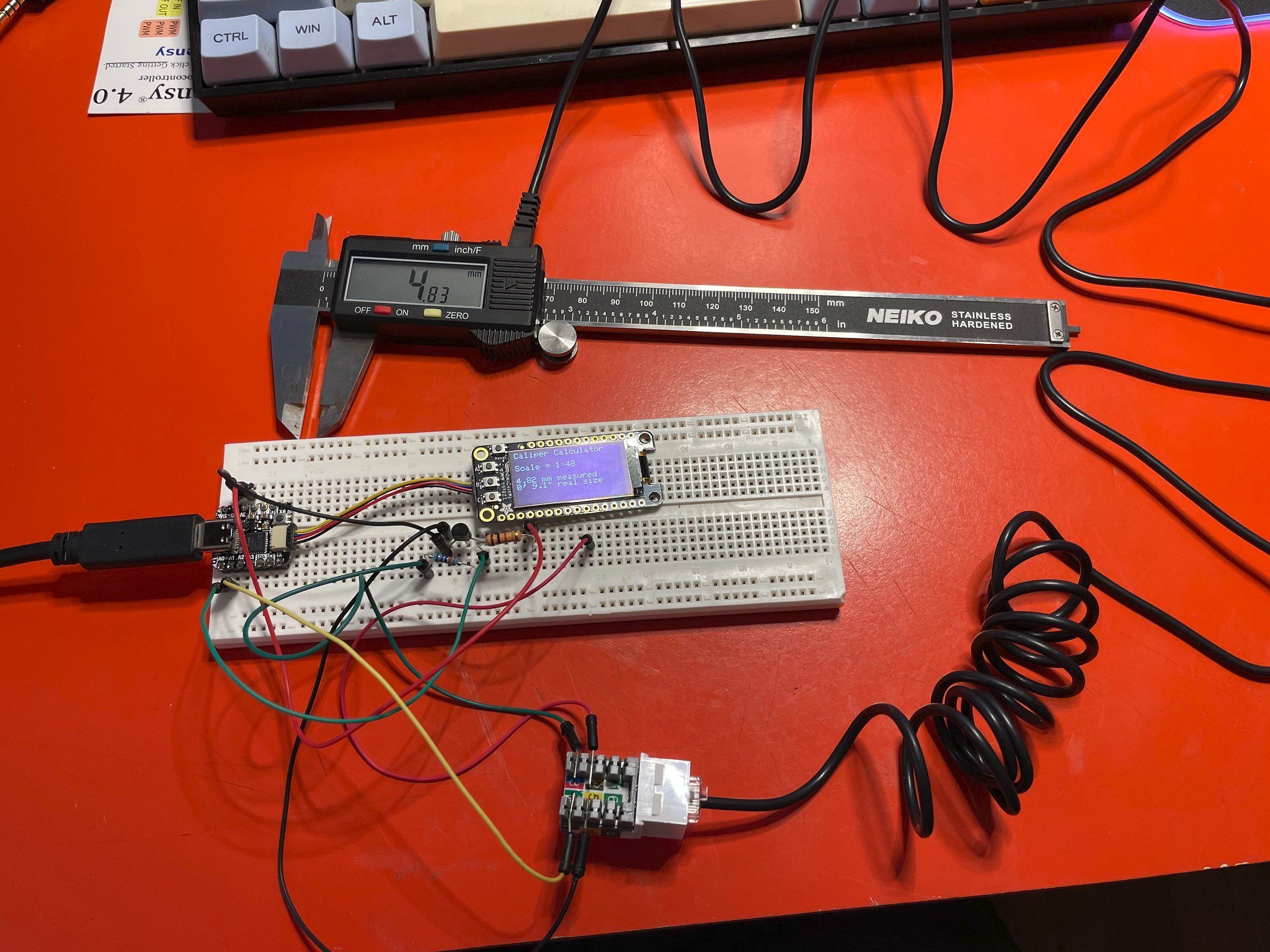
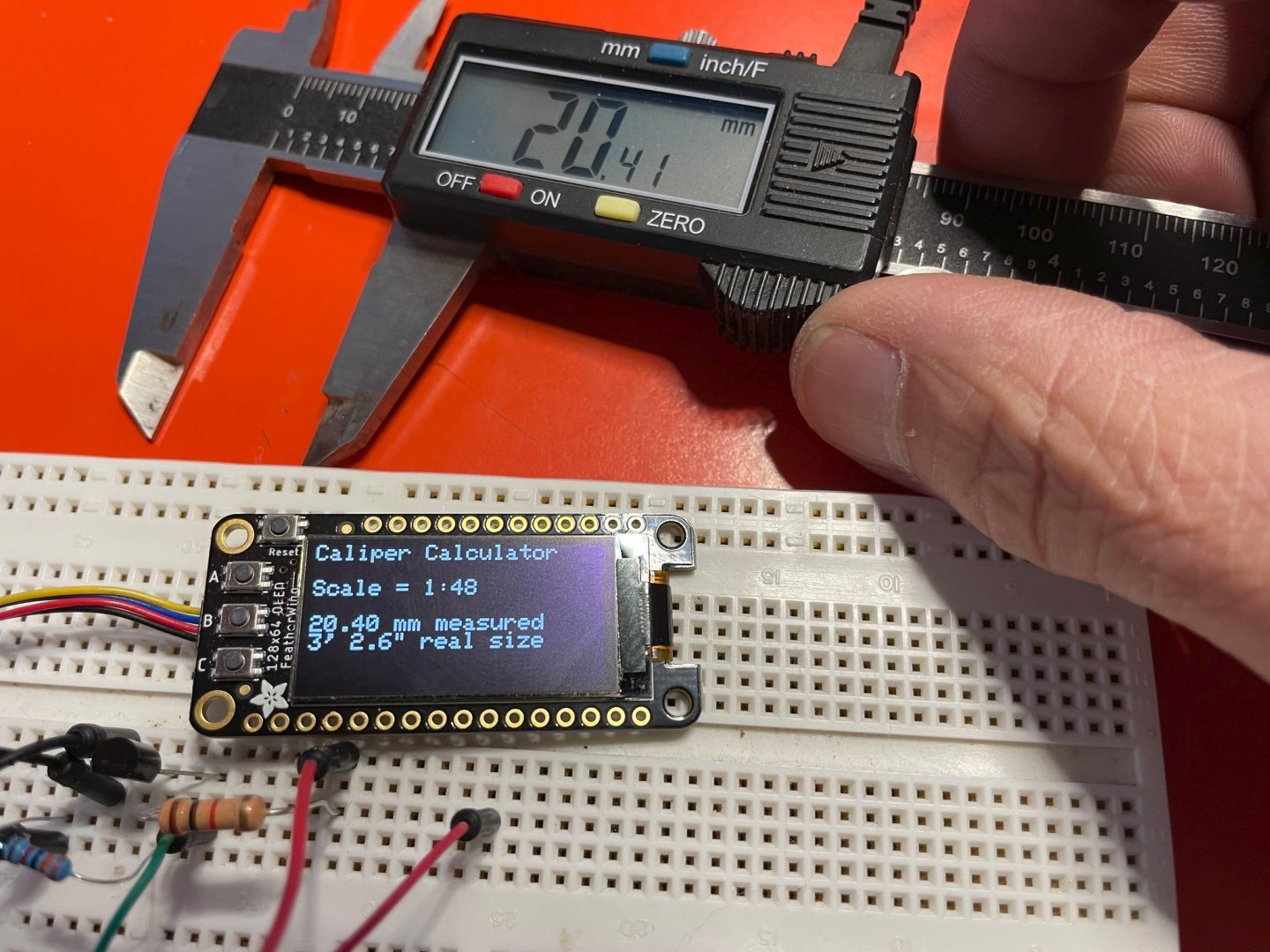
I'm probably not the only person who's often measured something with digital calipers, then gone and tossed the dimensions into a scale calculator to get the real dimension. So I came up with a little hack today to try and automate the process. Here's a picture of the prototype... As you can see, the little digital display on the breadboard is showing the scale being calculated (1:48 which is hardcoded at the moment), the length measured on the caliper (20.4mm) and how large that would be at 1:48 scale (3 feet, 2.6 inches). As you move the caliper it automatically updates the display with new values. As background, it ends up most cheap calipers have a digital port on them. If you've got a caliper, look for a little slide off panel on the top with 4 contact stripes on the circuit board inside. This puts out a digital signal for a DRO (Digital Read Out), as the guts of these things are shared with or very similar to DROs for benchtop mills and such. Here's a bigger shot to show the whole thing. On the left of the breadboard is a little Adafruit QT Py dev board (Arduino compatible) which is plugged into a small OLED display. The cable coming out of the caliper takes ground plus data and clock signals to the Arduino. The clock signal is being boosted from 1.5v up to 3.3v with a little transistor circuit in the middle. I want to keep working on this as a smaller, more self contained device, obviously without so many loose wires. I also want to have it so you can set the scale you want and change units. One interesting feature would be to let it determine scale from a drawing. You should be able to take a ship drawing for example, measure off 10 feet on the drawing's scale, and have the device tell you what the scale of the drawing is. Then with that scale, you can start taking dimensioned lengths directly off the drawing. The cable by the way is a specialized plug that goes to an RJ-11 (phone jack). It's the same kind of plug used on DROs, and I picked up the cable from Little Machine Shop at https://littlemachineshop.com/products/product_view.php?ProductID=3483

-
Thanks, I appreciate the offer! I've been reading through the manual for the Katy again, and feel like I can glean a fair amount from just the manual. Sounds like I've gone down a similar path with a willingness to redo the deck layout. I've removed the forward deck house, and replaced it with a grating and forward stack at this point. In fact a lot like the Katy forward deck layout. One thing I can see in various pilot boat designs is that they have a very minimal bulwark - something that Chappelle's books refer to as a "log bulwark". I've been a bit tempted to carve down the bulwark height on the kit, but I also think I should just leave well enough alone at some point
-
Indeed I've referenced it quite a bit! If not for the complications of COVID I'd offer to buy you a beverage in exchange for picking your brain a bit. I am also in Corvallis.
-
I'm building the AL Swift Virginia Pilot Boat 1805 kit - one of the original versions from 1980's. I've seen several pictures of the Katy plans and indeed they seem far more detailed than what I have. I've considered it as a reference, and would love to get a copy of the instructions and plans to use as a reference (instructions PDF is online). I have a Model Shipways Flying Fish kit also from the 1980's, and the level of detail in the plans and instruction book are really quite amazing. I like how they show multiple ways to build various things, from the realistic but difficult to the simpler.
-
She's not caught on fire or gone dark on me yet
-
Hehe no fires yet
-
¡todo el mundo necesita un gato o dos ayudantes! Everyone needs a helper cat or two!
-
And that very well may be just what I do I guess. I mean I did rewire my MG Midget with a new custom-made harness, setup the LED headlights with relays, plus replace all other bubs with LEDs...
-
That I assumed, yes. I wasn't referencing square rigging in terms of using it - only that the reference I mentioned had it, but that it wasn't applicable. I want to stick with basic gaff schooner rigging, no square. Keep the masts and other things as they are as much as possible. And interesting in terms of the crew size RE: sailing back, etc. Really I'm just trying to make my crappy little old kit have some realism rather than just building it by the instruction book. Lots of things seem (and are) big shortcuts, and I'd like to understand what the correct approach would be. I doubt for example a stay is just a rope strung between two eyes.
-
As a preface, I've been gathering various references for 2 masted schooner rigging to better understand how my lowly AL Swift/Virginia Pilot Boat 1805 would be rigged if real. I also realize rigging depends a lot on the size, the year, the country of design origin, etc. I've yet to find a good solid rigging reference matching the ship, which I believe you'd call a 2 masted gaff-rigged schooner(?) but I've found some reasonably similar designs with clear overlap in rigging. Designs from same country, approximate year and size. And to my subject line question, I want to know if I can (or should) selectively take these shared similarities in a design, and use them as reference. For example Lennarth Petersson's Rigging Period Fore-And-Aft Craft seems an oft-sited reference, and it has an American Schooner section based on Experiment, built in 1808. Clearly nothing related to square rigging applies, nor extended jibboom and a few other differences. Plus it's larger so a heavier fore & main stay, additional shrouds, etc. But then the drawings of the fore and main throat & peak halliards plus vangs seem reasonable, and common to both regular and topsail schooners. Thoughts?
-
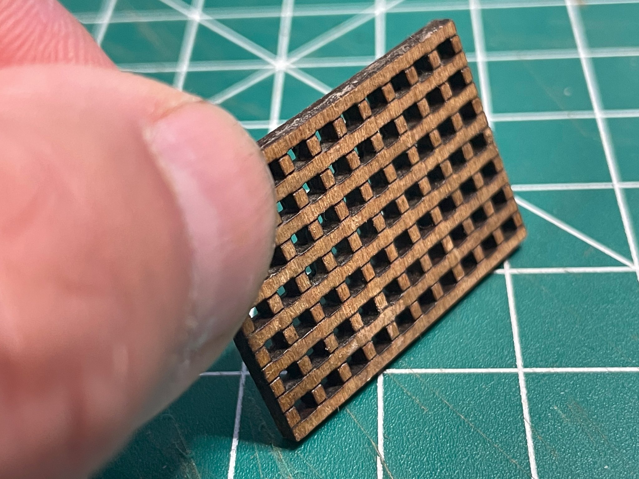
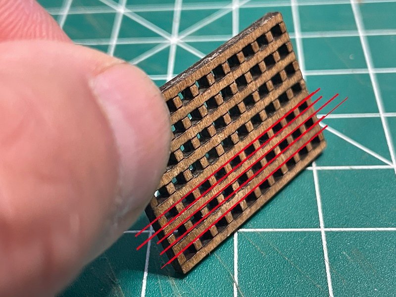
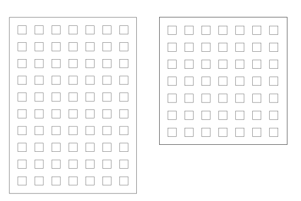
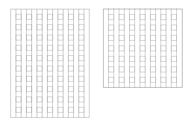
I took my first stab a while back at making a single piece laser cut hatch grating. This is a style used on Vanguard's grating set. Here's a picture of one I cut out using some Maple, about 1.6mm thick. It's not as clean looking as a machined or cut wooden grate, and there is a bit of risk that excessive visible grain in the wood will not look right. But it's guaranteed to be at right angles, and it makes framing a "perfect" hatch a bit simpler. To some extent the char is a drawback, but I like the "dirty" look of the grate, as this is more the style I like. Also, a benefit of the laser char in the square holes is that it darkens the grating, creating more of that "and below is a dark area" illusion. I actually applied flat varnish down in the cut holes to help fix the char so it wouldn't smudge. To create them, you end up making two passes on the wood with the laser cutter: a cut pass to make the holes and cut around the outside, and an etch (partial cut) to create a visual separation with the sections. I've annotated the picture below with some red lines showing where the etch lines are. The etch lines create the illusion of the vertical pieces being separate. To make the cuts and etches, I used Inkscape (a free vector editing program) to create two patterns. First the cut lines... To create the above layout, I started by making a 1.6mm square, then began duplicating it at an even spacing until I had an area big enough for my grating. Then I put a bounding box around it for a final separation cut. Then the etch lines, which I just created using the above pattern to let me know where they should be I actually created these on top of each other in editor layers so that they would line up. Here is a picture of them together in the editor. Then I exported the cut and etch layers into separate SVG files (one for cut, one for etch), which I then passed to the Glowforge laser cutter to create the cut and etch tasks. Here are a few things I've though of doing beyond this first attempt... Just create an entire sheet of grating without any cut bounds. Then I could just cut out any shape I wanted to any size (in grate grid square steps). If I want my grating to be a very specific size (width and height), it would be easy to just rescale the entire cut to match exactly the size I want. Using individual grating strips, I can't resize the grate, as they are forced to be dimensional increments of the thickness of your wood. If putting a bounding cut around the outside of a sized grate, leave a few small gaps so that the cut doesn't go completely around the whole grate. The main reason I'd do this is because when the outside cut completes, it will sometimes drop the piece of wood a small amount if it's not sitting flat on the cutting bed. That means subsequent cuts and etches may not quite line up right. Leaving the small gaps means the grate section won't fall down.


-
I have an Ender 3 Pro, which I quite like. That said, there are some updates to it that I did perform which made it a lot easier and better to use. Some of the things I did were to specifically to reduce noise, as my printer is on my desk near my work area. I upgraded the control board and screen with a BIGTREETECH SKR Mini E3 V2.0 32Bit Control Board with TFT35 E3 V3.0 Touch Screen Display. This both greatly quiets the stepper motors but also gives you a nicer user interface. An ANTCLABS BLTouch Auto Bed Leveling Sensor. This REALLY helps with bed leveling and creating a higher quality print. Micro Swiss All Metal Hotend which I got for printing TPU filament. TPU is rubbery and not normally something for modelling, but I was using it for another project. Spring steel heat bed platform with PEI coating. This goes onto the print bed, and is easy to just pop off and remove your print when cool. You can flex the sheet and have it just pop off the bed without any scraping, etc. New Noctua brand fans to replace existing ones. These are much quieter! Now all that said, by the time I was done with all this, I'd spent a lot of money - probably as much as (if not more) than the original Ender 3 Pro. In hindsight, I probably should have just bought a Prusa I3 MK3S+ printer kit. They basically have most of the things I added, and works right away. Oh one other thing I have done which I like. I have a Raspberry Pi running the OctoPrint package. It gives you a full web interface to your printer, where you can submit jobs, monitor jobs, etc. No more SD writing print jobs to SD cards on the PC, then moving it to the printer, etc.
-
Any other Glowforge laser cutter/etcher users?
Tim Holt replied to Tim Holt's topic in 3D-Printing and Laser-Cutting.
Experimentation definitely does pay off. No direct air assist but it does have an integrated exhaust fan as it's a closed case. We have it hooked up to an air exhaust system at work to pull the smoke out. It's pretty aggressive at pulling the smoke off, but doesn't blow directly onto the cut. The cutting bed is a raised metal honeycomb and the air pulls down from below, which means plenty of smoke until the cut is all the way through. Just doing some reading and it seems some people are making mods to their Glowforges to add air assist. I may have to look into this! -
Anyone else using one of these? I have access to a Glowforge via a Makerspace at work (large tech company), and lately have been experimenting with various hardwoods in it. Like probably anyone using a laser cutter, char (burnt) edges is a common issue. But then so is not cutting all the way through, which means a part can't be separated out. One thing I've sort of learned through trial and error is that sometimes the answer is to turn down the power of the laser rather than speed up the cutting. Initially I kept just pushing up the cut speed, but it proved to be more effective for the wood I have to use a lower power on the laser (from 100%) instead. Still experimenting, though getting closer to a good cut setting for thin (1.6mm) hard maple.
-
Resin printers really are a game changer compared to typical FDM (typical filament type) printers. That said I've seen some pretty amazing clear prints out of Prusa and other printers that had been very tightly tuned. Things like automatic bed leveling, stepper PID tuning, direct drive instead of Bowden tube, etc. can help a lot.
-
OK interesting. I was watching your demo videos, and noticed your initial twist time with the drill is pretty short (about 9 seconds) but then it's geared up so a lot more revolutions occurring. Then the laying up is much longer (20+ seconds), but then that's just 1:1 with the drill revolutions. That's not very precise given the speed variation of the drill, but it got me curious just how many actual revolutions were occurring in that video example - or rather what the ratio was. I'm just wondering if there isn't some base theoretical ratio for different setups for rope size, thread type, etc. Since I can count my revolutions precisely, it would be nice to dial in a desired count for each step based on that ratio plus how long of a setup I was using. Sort of like having a torque wrench and a bolt torque table.