HOLIDAY DONATION DRIVE - SUPPORT MSW - DO YOUR PART TO KEEP THIS GREAT FORUM GOING! (Only 13 donations so far - C'mon guys!)
×


Tim Holt
-
Posts
196 -
Joined
-
Last visited
Content Type
Profiles
Forums
Gallery
Events
Everything posted by Tim Holt
-
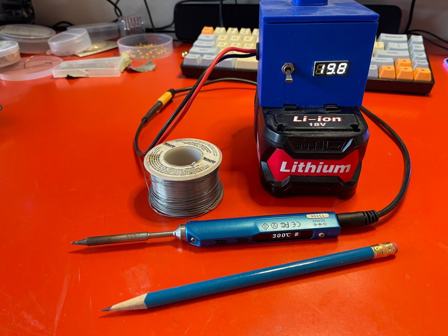
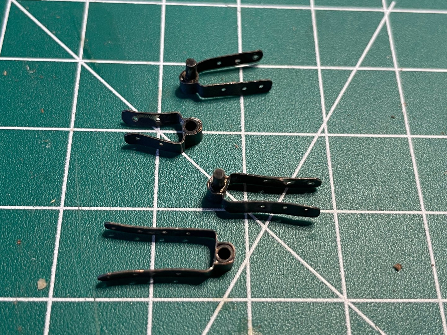
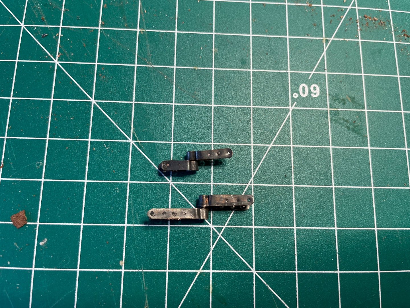
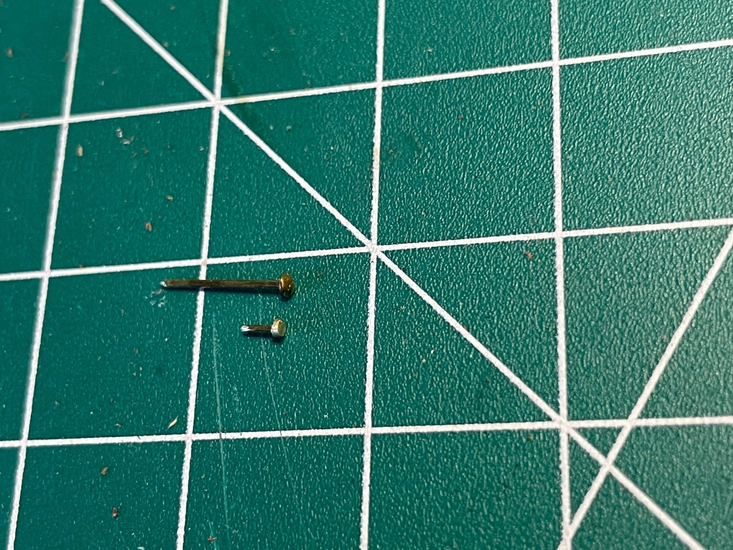
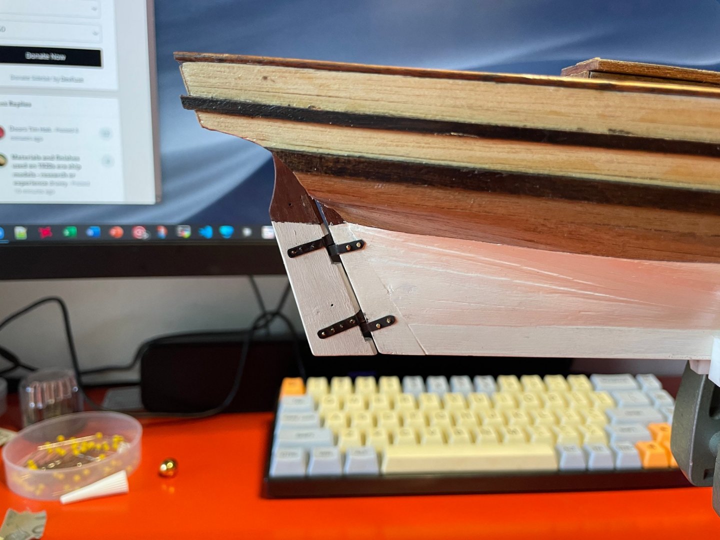
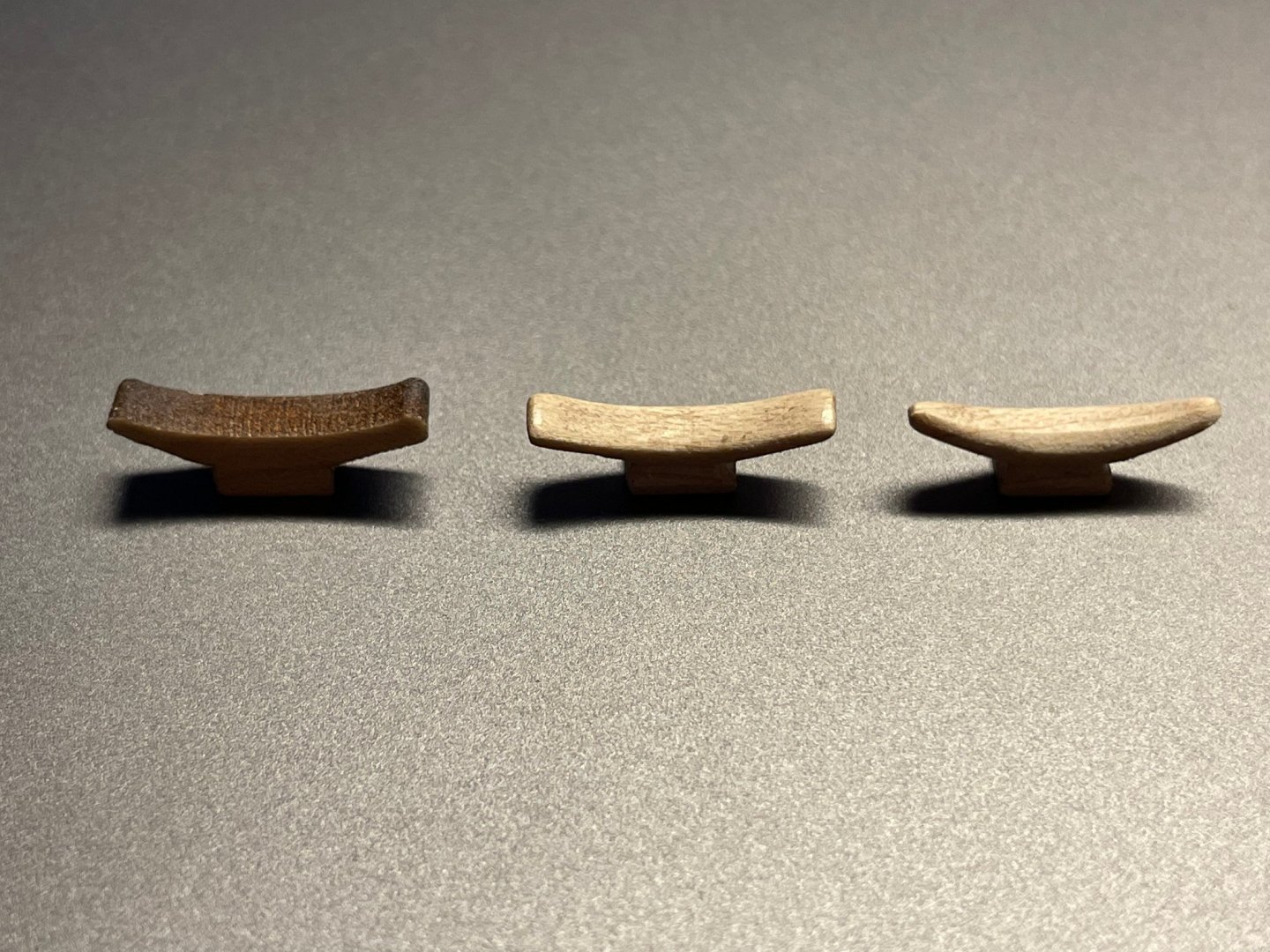
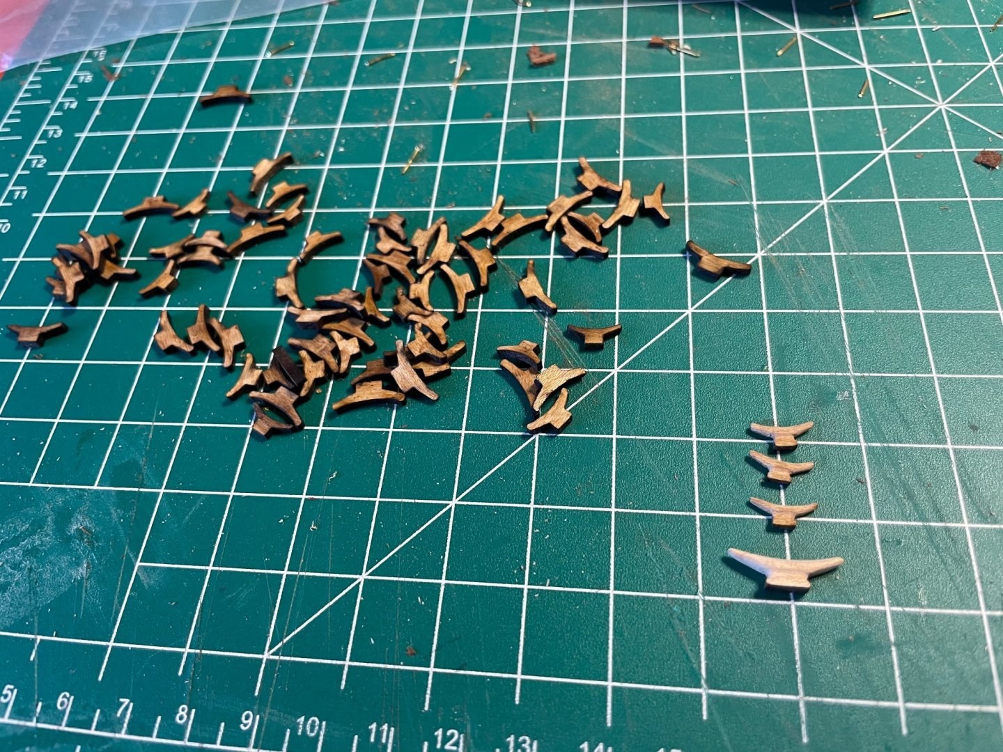
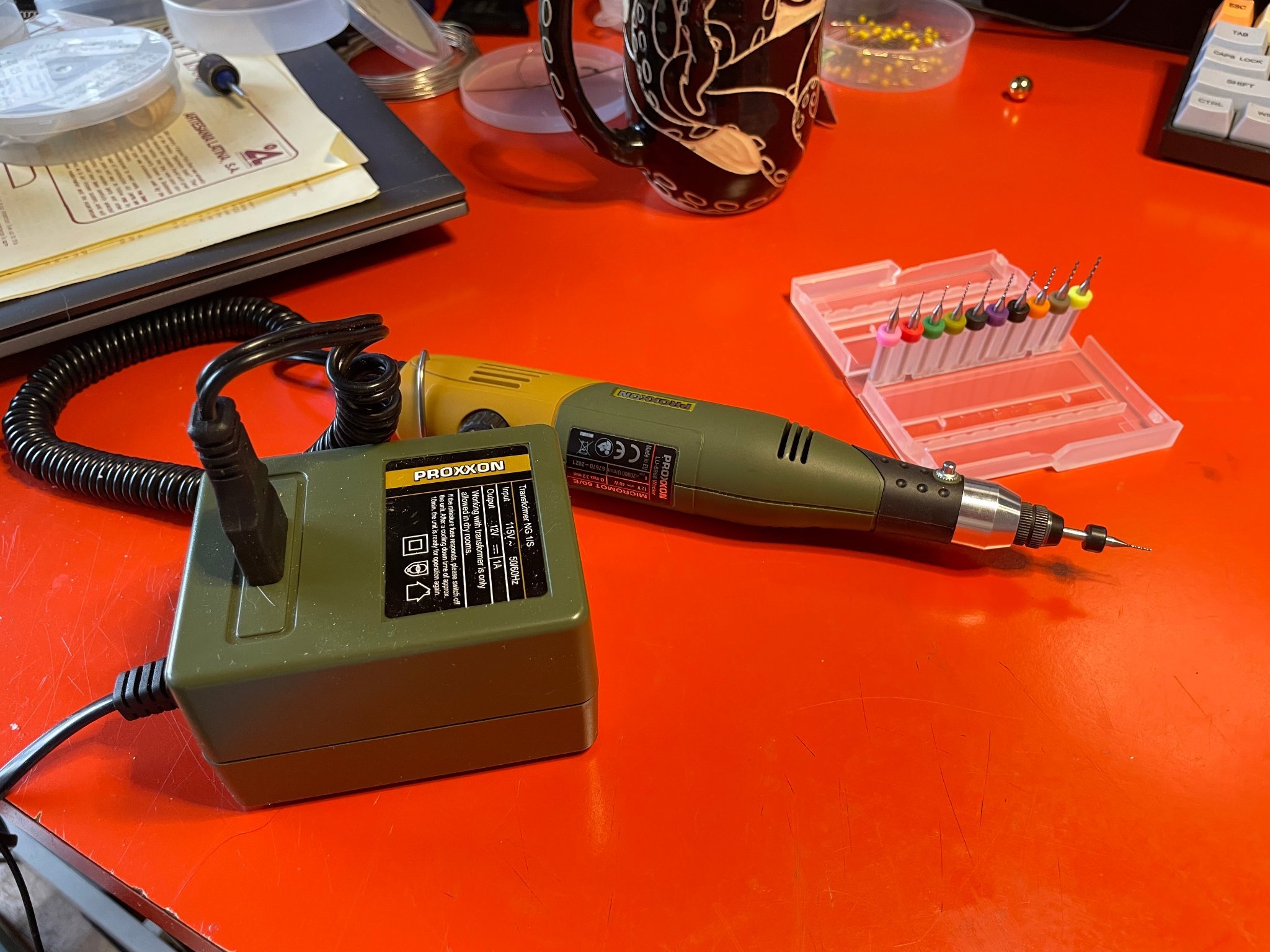
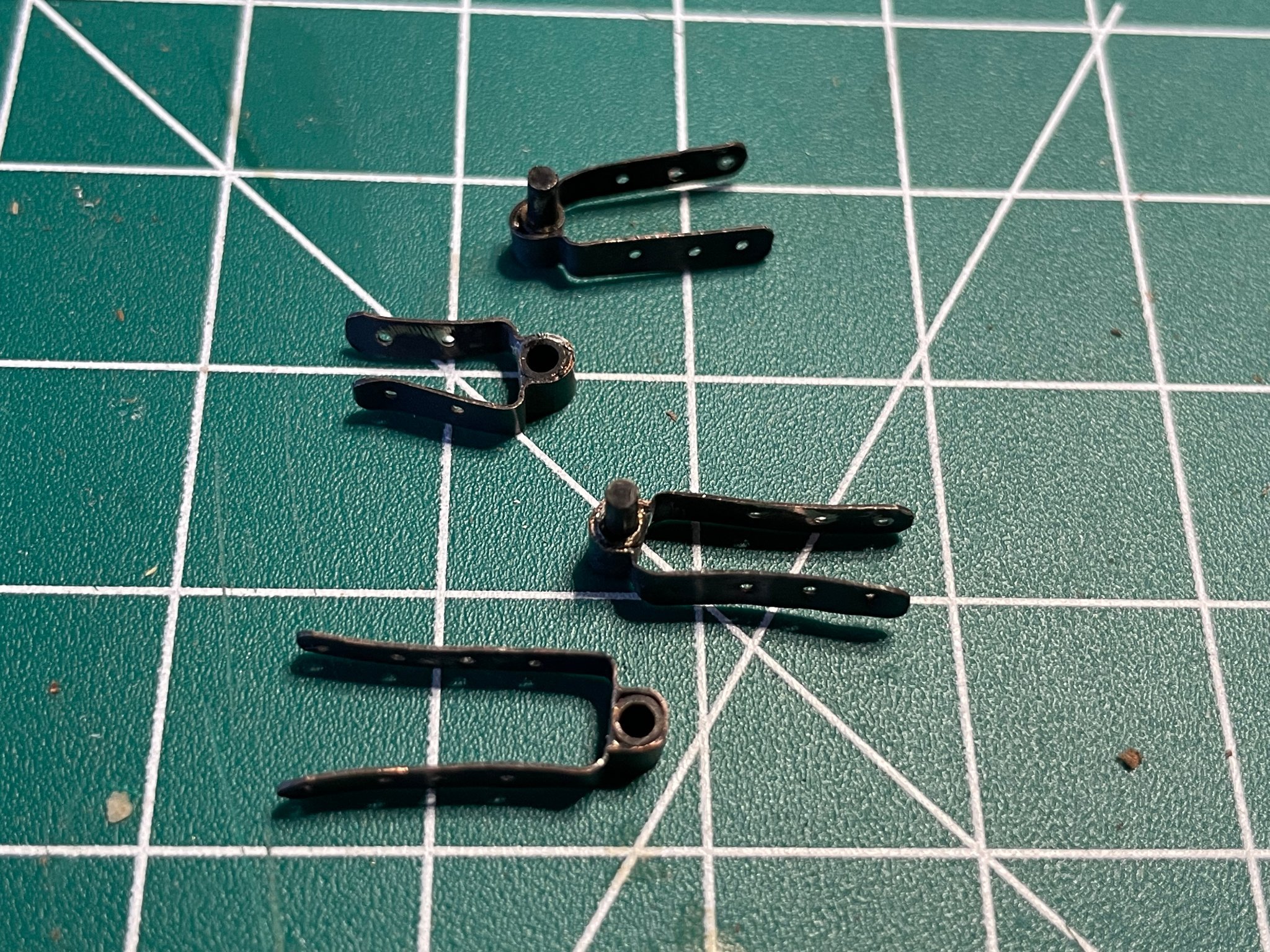
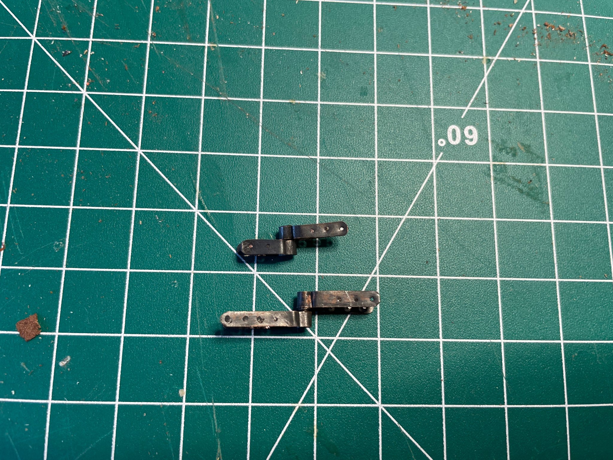
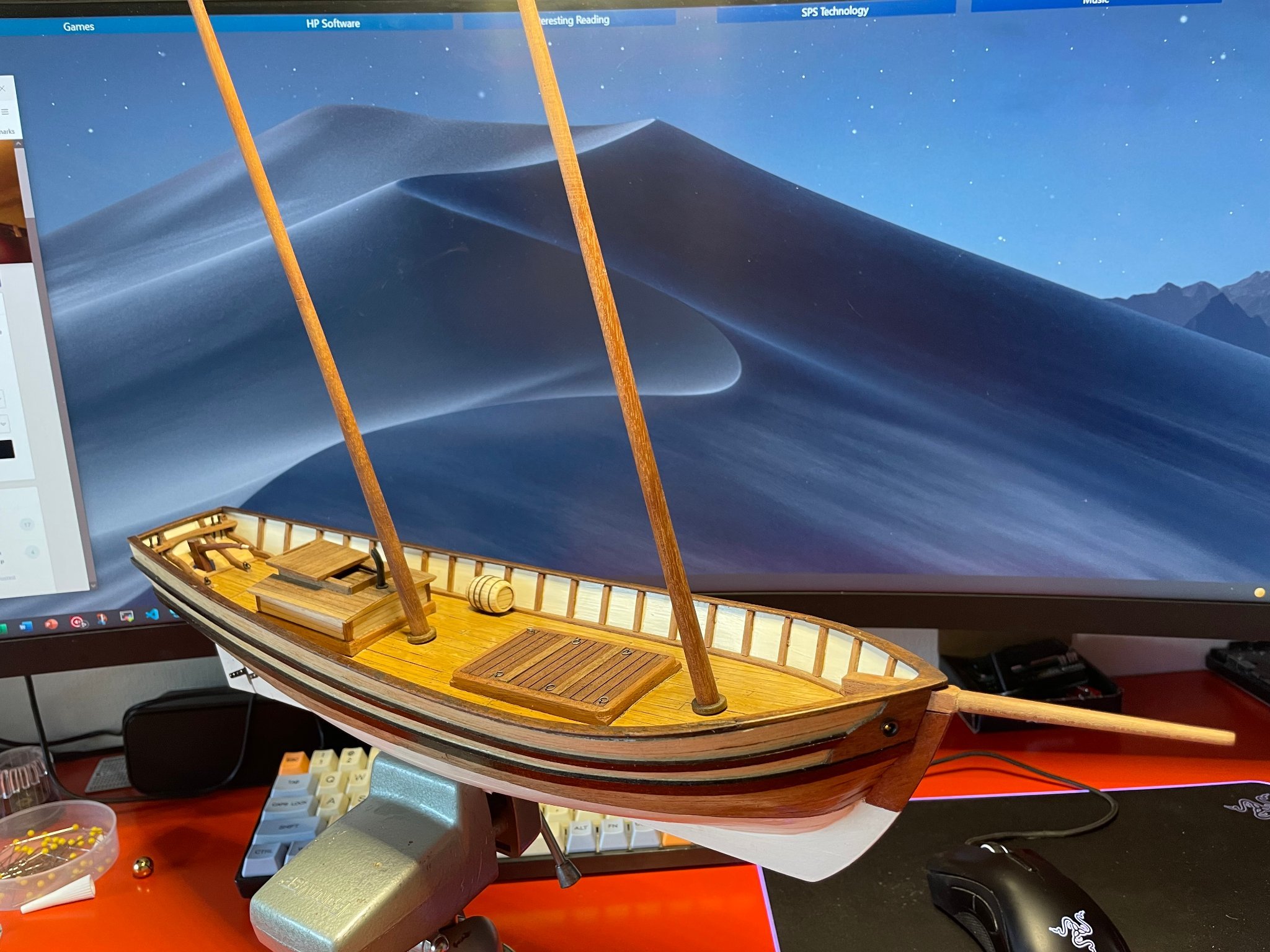
 Been experimenting a bit the last few weeks with pintles, gudgeons, laser cutting, rudders, and tillers. Also delving into blackening various brass parts with Birchwood Casey Brass Black. Rudder and Tiller #1 First, building the rudder. The kit's rudder is just a single piece of wood, which I didn't shape much beyond putting a bigger bevel on forward edge, plus trimming the length to not stick up too high into the stern. I also spent some time carving down the tiller that came with the kit (a massive beast) into something that a person's hands could perhaps actually grip. I used this design from Davis's The Built-Up Ship Model. Dimensions are a bit shorter so it wouldn't extend the full 9 feet, else the poor tillerman would have no place to stand to actually operate it. The tiller is then mortised into the rudder. Pintles and Gudgeons I actually made these several times before I got a set I liked. I ended up using some thin 30g copper sheet, then small bits of brass tubing and rod. I followed the "Making the RUDDER - RAGUSIAN CARRACK" video from Olha Bathvarov on YouTube for reference and encouragement. I also used small brass pins that I cut down then ground the heads smaller. Then treated all with Birchwood Casey Brass Black. Rudder and Tiller #2 With everything made, it was time to put it all together. Here is the final result. She's starting to look like a real ship now! Oh yes in that picture you can see a little barrel resting on the deck. This was one of the Syren Ship Model Company's QUICK barrels, which I got in the mail, along with some nice blocks. Laser Cutting Having access to a Glowforge lasercutter and a good collection of thin hard maple (unused violin sides), I decided to try making some belaying cleats to replace the oversized ones that came with the kit. I used a small round file and fine (220 and 320) sandpaper to clean up the results. Here are some pictures of the sequence - from raw cut, initial cleaning, and final cleaning. Once I had some good sizes and a pattern worked out, I went ahead and cut a bunch of them with some varying sizes for future use. Tool Notes I ended up getting a new Proxxon Micromot and some fine drill bits last week. I have to say I love that tool - it's helped me a bit with precision and is a lot easier to use for drilling small holes. I also wanted to share a picture of my soldering setup. I'm using a TS100 style soldering iron, which seems pretty popular now days. I use it a lot for electronics projects, but also for my brass and copper soldering. Here's a picture of my setup, and as you can see it's quite small (pencil for reference). I actually use an 18v cordless drill battery to run it, with a home-made box on top with a power switch, holder, and meter showing battery voltage. It heats up very fast, and puts itself to sleep if not moved for a while. You can see the little readout on it showing the temperature. Next Up I'm currently reading a lot about rigging, as before I start attaching various rings, cleats and bitts to the deck, I want to get a better sense of how the rigging really should be. I'm pretty sure the as-instructed rigging of the kit is lacking a lot in accuracy and detail, and want to put some time into thinking/rethinking the rigging to be more accurate. @Dr PR's Topsail schooner sail plans and rigging thread has been a good read, and I have a copy of Chapelle's The Search for Speed Under Sail and The Baltimore Clipper: It's Origin and Development on the way via AbeBooks for more reference. Ah yes and some Gutterman Mara 70 and 100 on the way from WAWAK - this rope making thing seems intriguing...
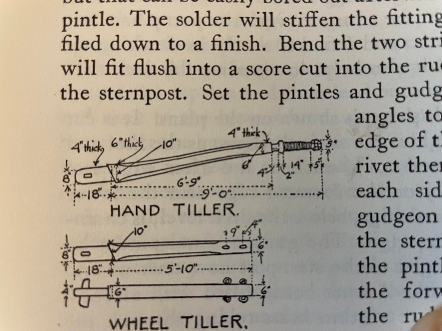


- 44 replies
-
- 3
-

-
- first build
- Artesian Latina
- (and 1 more)
-
Doors
Tim Holt replied to Don Case's topic in Building, Framing, Planking and plating a ships hull and deck
Just trying to use logic (and not history), irrespective of the year, country, etc. it's always true that decks can become awash - some more than others. So it makes sense to always have have a sill or continuation of coaming without a direct opening down to below decks for water. Obviously if you don't, water's going to come in if the opening isn't fully sealed. I'd imagine any ship without a sill would get soaked now and then, and the ship's carpenter would grab some scrap of wood and nail it on to stop "that dammed water from coming in because some SOB thought opening the door when the deck was awash was a good idea." -
Doors
Tim Holt replied to Don Case's topic in Building, Framing, Planking and plating a ships hull and deck
Created by cutting holes in walls - just like they did for the windows. Often if you take the stairs up to the next floor on the boat you can observe this better. -
I like how those stanchions are put in place. It seems to make them line up well with the hull shape, plus gives good strength.
-
Just wanted to add a note on this build. I've got the old solid wood hull version of Model Shipways Flying Fish that I bought back in the early/mid 80's that I started long ago, and realized was over my head. I have to say, from the picture I saw it looks like the same plans as mine. The plans and the instruction book are just incredibly detailed and wonderful compared to the other 3 kits I pre-inherted/bought from AL. The old Model Shipwatys book and plans are gorgeous, and someone back when went to a lot of work to document and illustrate how to build it. Not just how to build it, but how the real thing worked, and various ways to do it from easy to complex. It even suggests you scratch build some of the cast parts if you're feeling like making something better. I still have the kit, though at the time I did a pretty bad job on the hull. Knowing what I know now in theory, plus having access to better materials and tools, I'm pretty tempted to use the plans to work out a scratch built plank on bulkhead hull to finish it off - not so much from what the kit has, but just from how good and detailed the plans seem.
-
Hey just a FAQ request for you vendors out there who sell stuff that's got a single dimension - blocks, cleats, and hearts come to mind for example - give us beginner buyers all the dimensions. For example, is a 1/4" block 1/4" wide? 1/4" tall? Or is that the diameter of the sheave? PS I do now have a gorgeous set of blocks now (thank you @Chuck!) that I will happily keep, and no doubt use on a new future project. PPS I GLADLY have ordered (based on the quality) a set of 3/16" blocks (which is what I needed (I think)) PPPS I thought it was sheave size
- 1 reply
-
- 1
-
-
One observation on Brass Black flaking off I've had. After a full-strength application and a rinse, I can let it sit for about 24 hours, then just wipe it down with a paper towel, or go over parts with a stiff brush. That removes the loose stuff and leaves a nice dark almost gray iron look. I haven't tried it yet, but I imagine for little parts I could put it in a container with some mild abrasive (cornmeal?) and just shake it for a bit to clean them.
-
I’ve had a regular filament type 3D printer for a few years, and it’s great for some things. But resin is definitely the way to go for finer precision items with odd shapes, detail, etc.
-
This sentence out of “The Anatomy of Nelson’s Ships” by Longridge caught my eye today… “The keel is prepared as a beginning; use an old seasoned straight-grained piece of some hard wood - such as a bit of old mahogany table top.” Not a direct source of lumber such as a seller, but old furniture theoretically could work for some wood needs. Perhaps check with your spouse before you start carving up the dining room table though.
-
I've seen it now several places. See https://www.boatus.org/findings/16/ for example - second paragraph of the "Conclusions" section. A google search for "boat cleat size rule of thumb" has it pop up quite a bit. Yet to find it in any older references though.
-
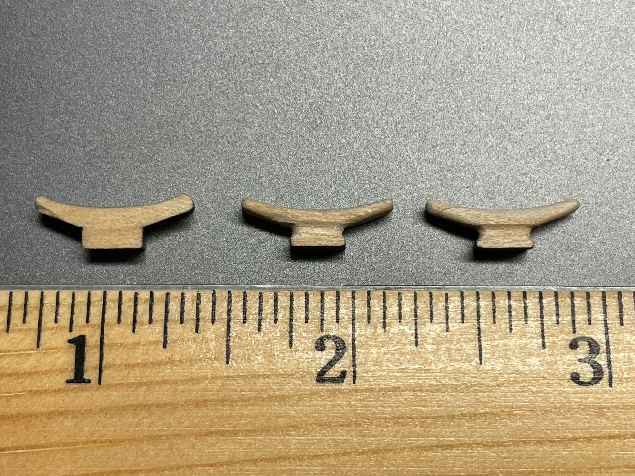
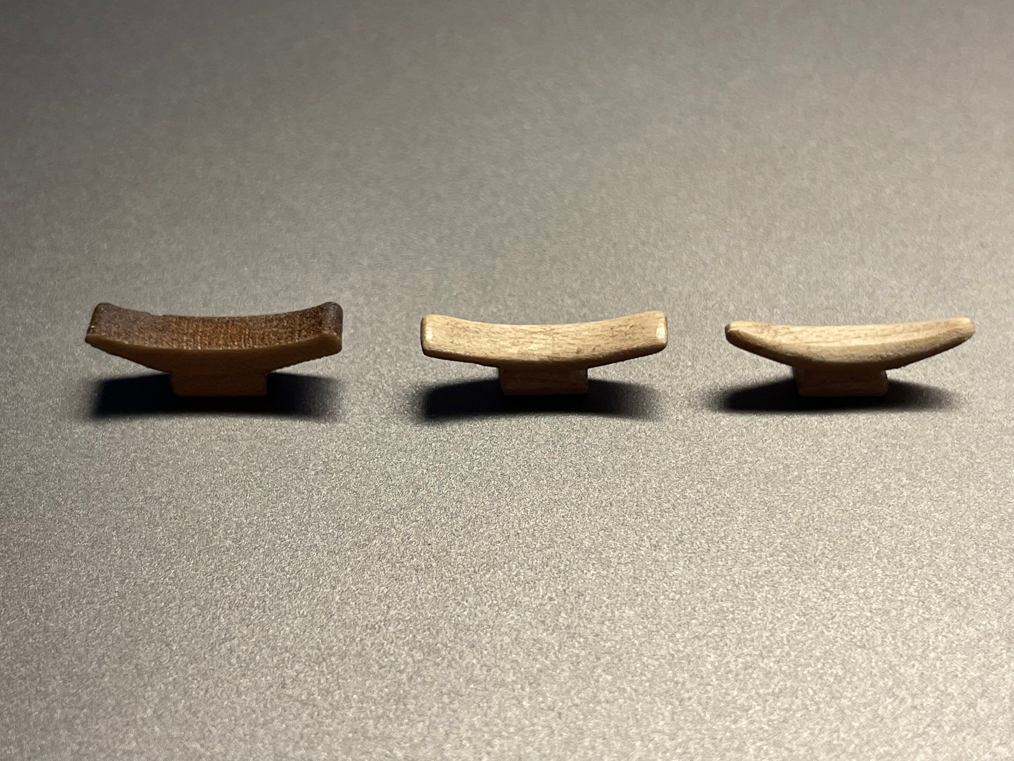
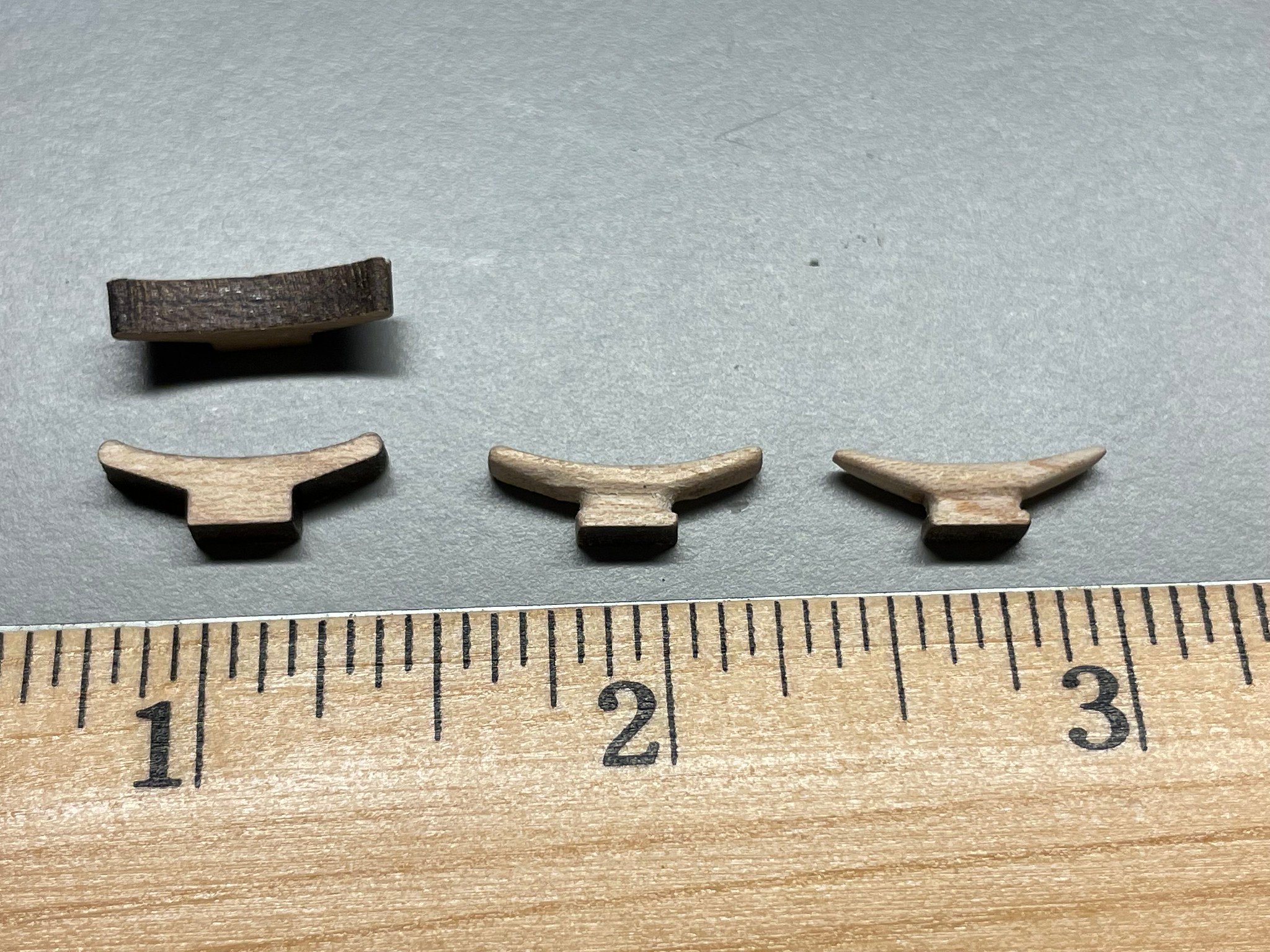
I guess in the spirit of just seeing how it looks, I've made a few of them to try out - partially to see how they look and partially to experiment with making them. I laser cut them out of some 1/8" solid maple, then worked down the shape using a small round file and sandpaper. Here's a quick picture of the sequence... With the laser cutter plan in hand, it's easy enough to scale them to an even smaller size if desired. and PS. These are still way too big (but it was a good exercise).

-
OK thanks all for the advice. It is a Morse Taper I believe. I do actually have access to a mini-mill at work, but it puts a bit of a crimp in the spontaneity as it were.
-
I've seen a rule of thumb for belaying cleats that for each 1/16" of diameter of rope you have, you should have 1" of cleat length - or belaying cleat length = 16 times rope diameter. So 3/4" rope would mean a 12" cleat, 1/2" rope an 8" cleat, etc. Does that rule of thumb still apply going back to the early 1800's? I ask because the pre-made belaying "cleats" (quotes because they are uuugly) that came with my old AL Swift 1805 pilot boat seem massive - 27 inches across and 5 inches thick if scaled up. They'd be for 1.7" rope using the rule of thumb. I want to make some new ones, and am wondering about what size they really should be?
-
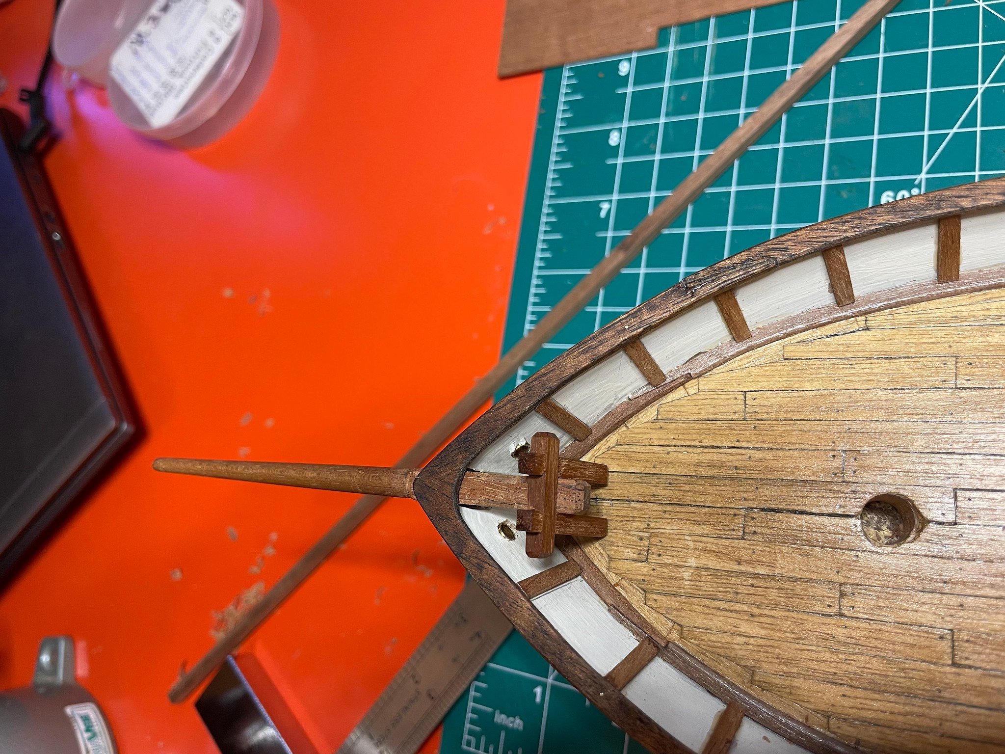
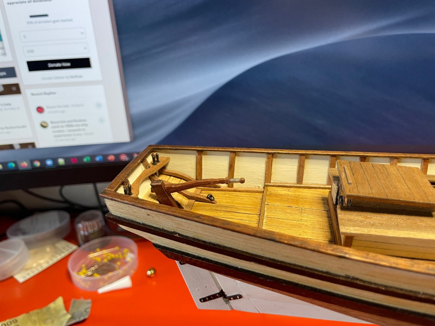
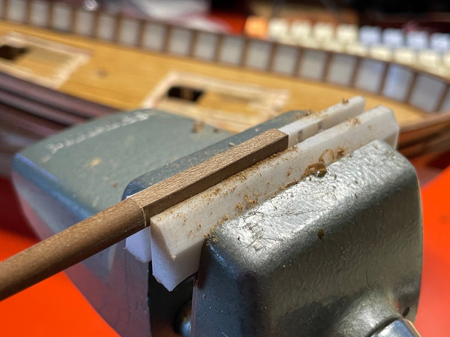
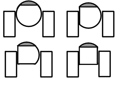
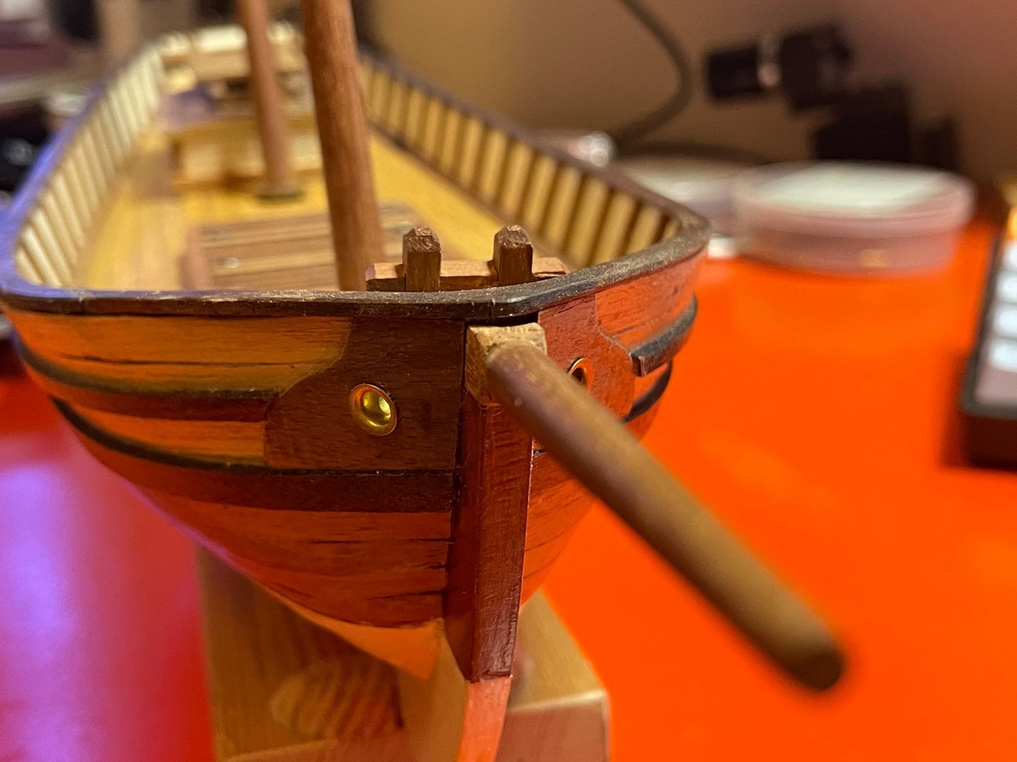
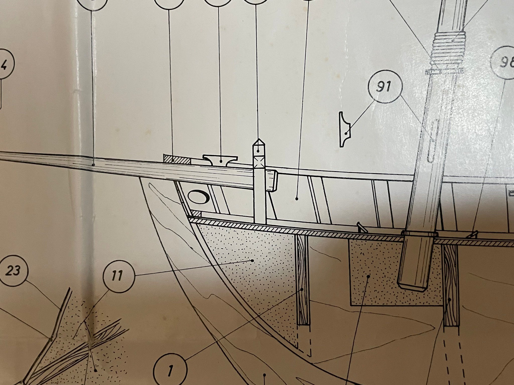
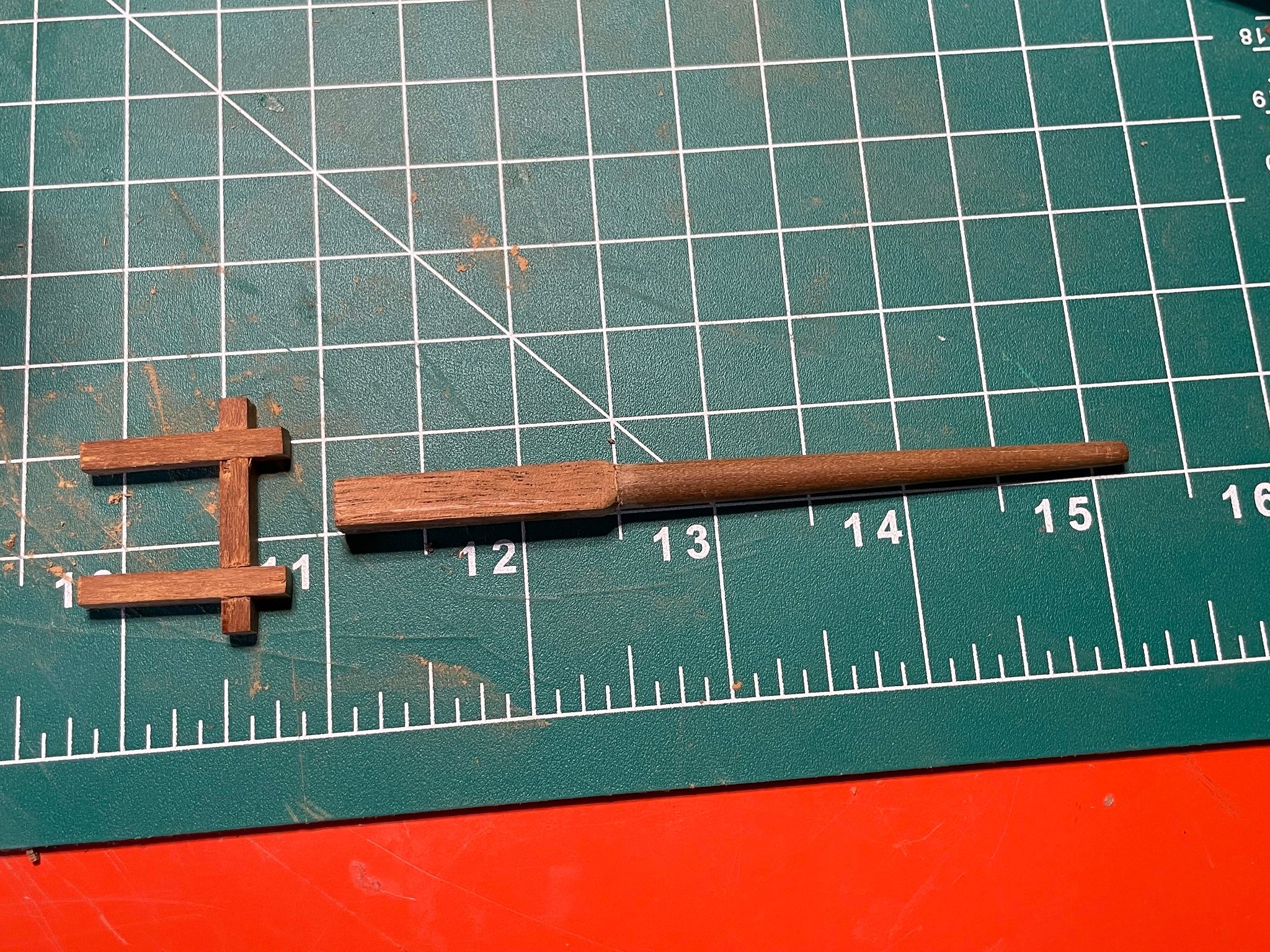
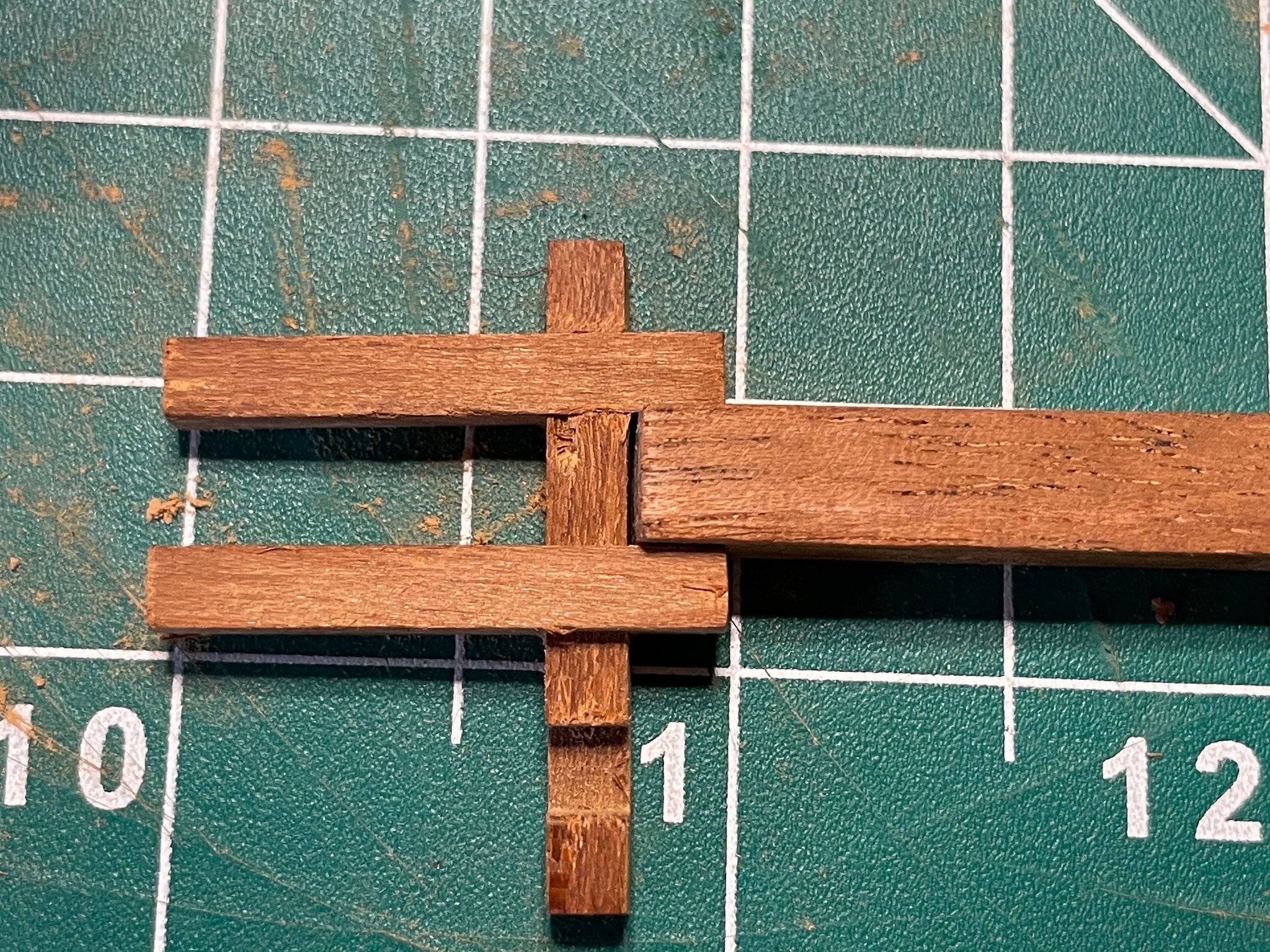
OK part two. So that bowsprit. The way the model had it mounted just didn't seem right. Here's how it's presented in the plans. Basically that bitt was supposed to hold it in place, yet a) there was no actual hardware holding it in place vertically, and b) the vertical posts of the bit were a LOT farther apart than the width of the bowsprit. So it really wasn't obvious how it would actually be held in place. What I ended up doing is not tapering the last 3 or so centimeters of the bowsprit from bow to bitt, and also squared off the non-tapered part. To square it off, I first made one face flat with a file, then chucked it in my vice with that first flat face on one jaw. That gave me a new round side now at 90 degrees to the first flat, and flatted it. Then rotate again and so forth. Here's a sketch of how this works out, with the gray areas being the parts removed. It assumes that the vice jaws are pretty good and parallel. And here's the final state still in the vice. Then I glued 1/32" mahogany to the newly flattened sides, and cleaned it all up to create a now squared off bowsprit. Here's how that looks, along with the bowsprit bitt as it came with the kit. You can see how wide apart the posts are, and how it's not got a chance to really hold that bowsprit in place. Fortunately I was able to just cut a new notch in the crosspiece for one of the posts and trim the cross piece, making it match the now squared up bowsprit. Putting it all together as a dry fit, here's what I have now. Seems like it makes a lot more sense to hold that bowsprit this way. One bonus is that the now squared off bowsprit fits nicely between the two plywood bulwark sections, which weren't long enough to reach the very front of the model, so no place to drill a round hole for the bowsprit as the original plans had me do. I’ll add a gammon strap across the top later. Next up is adding the rudder and tiller. I’ve got the gudgeons and pintles made, but waiting on the brass black to show up for those.


.thumb.jpg.3d270885f2a8bfb9666ae6ceba32f537.jpg)

- 44 replies
-
- 5
-
-
- first build
- Artesian Latina
- (and 1 more)
-
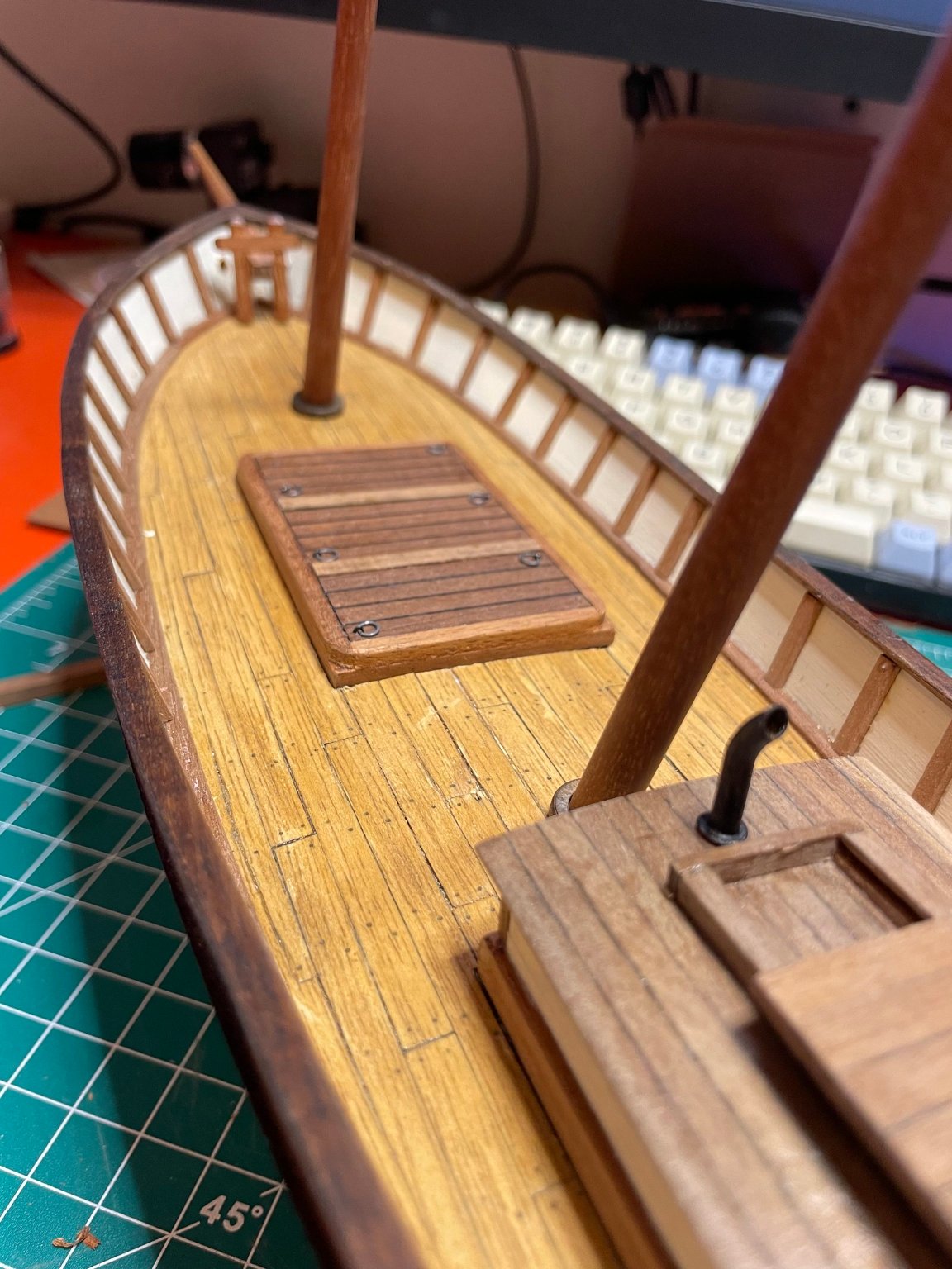
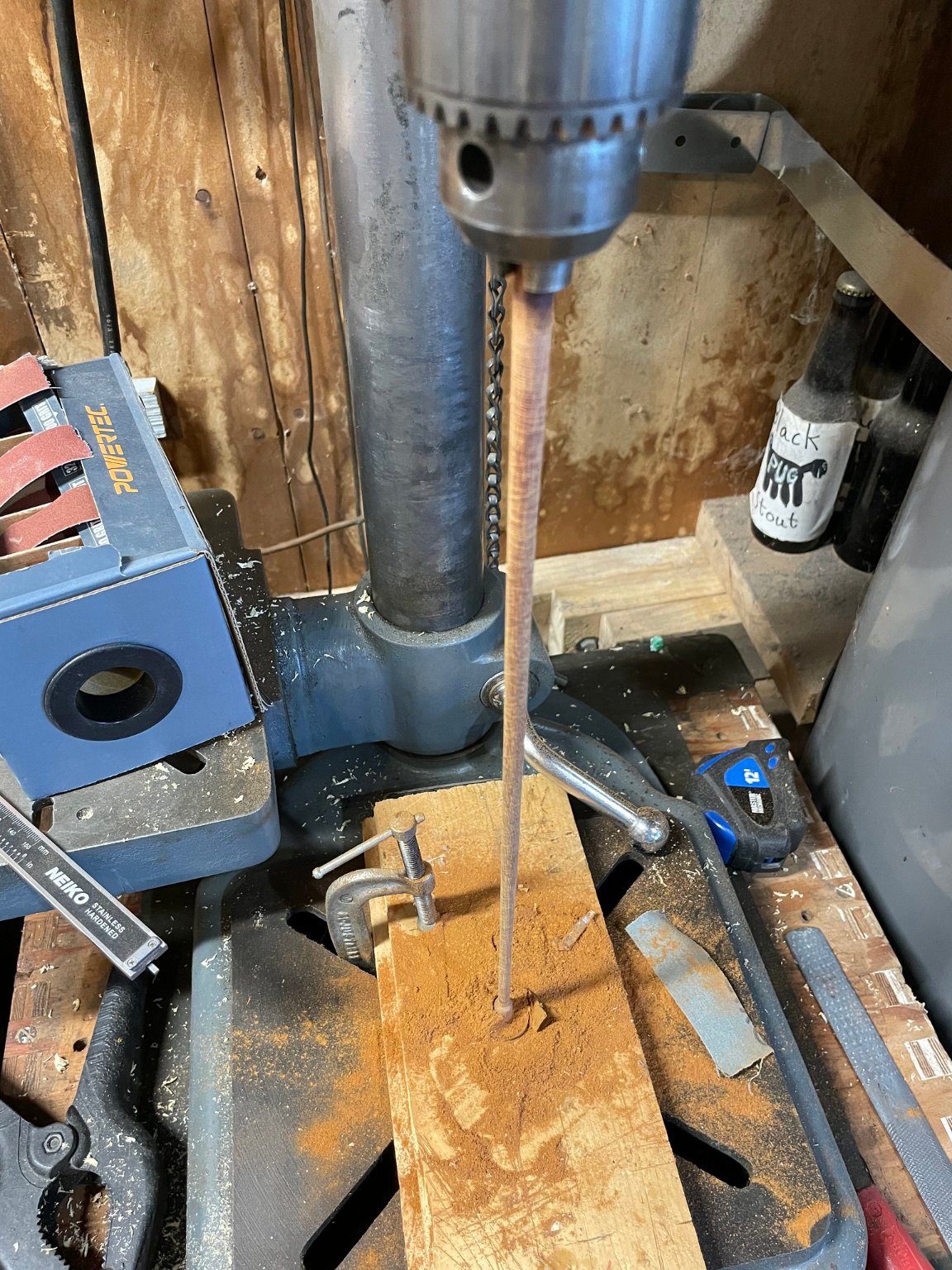
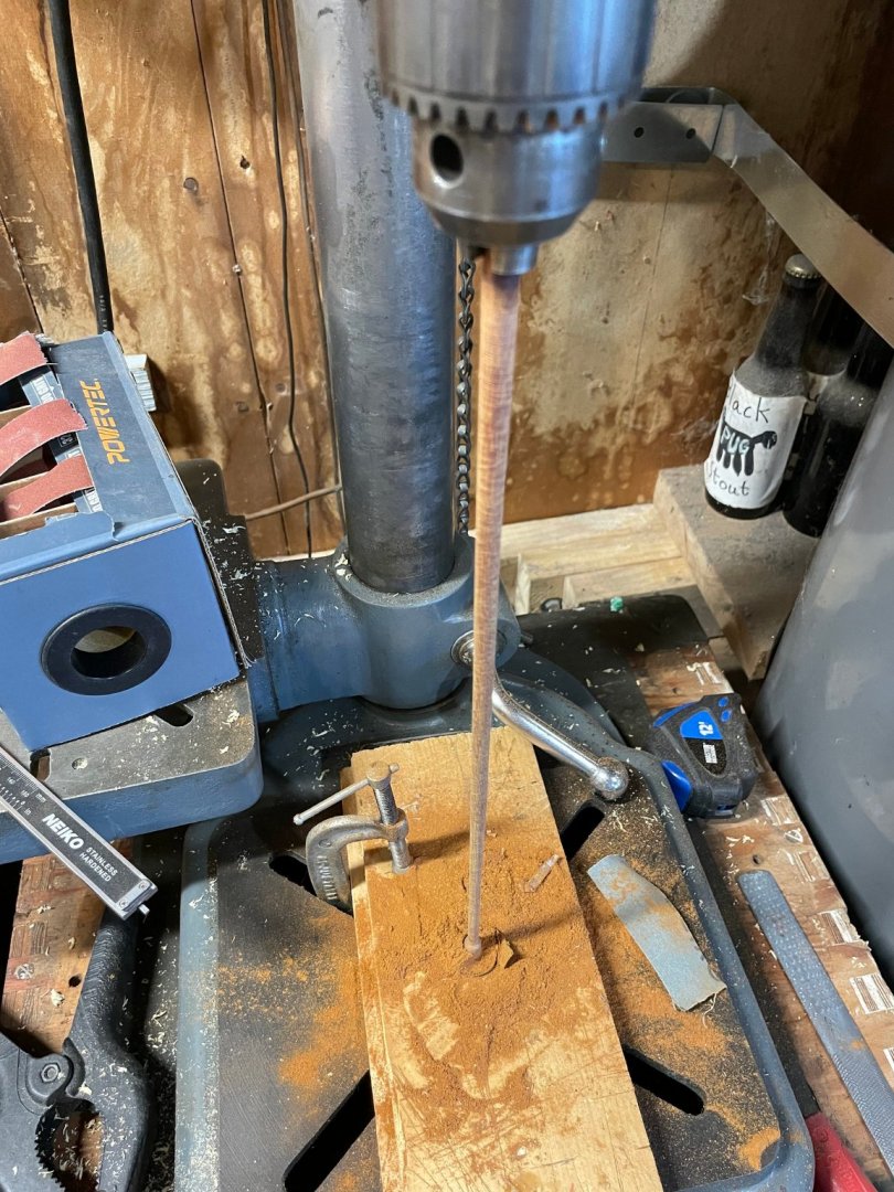
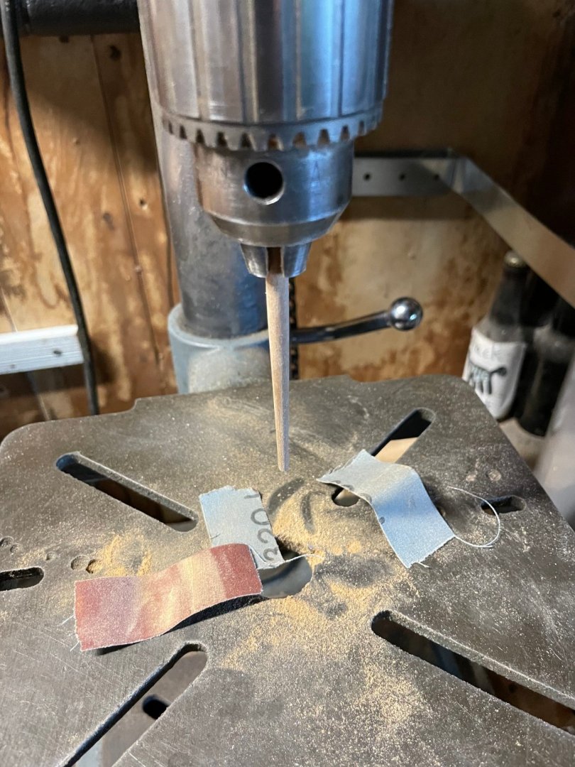
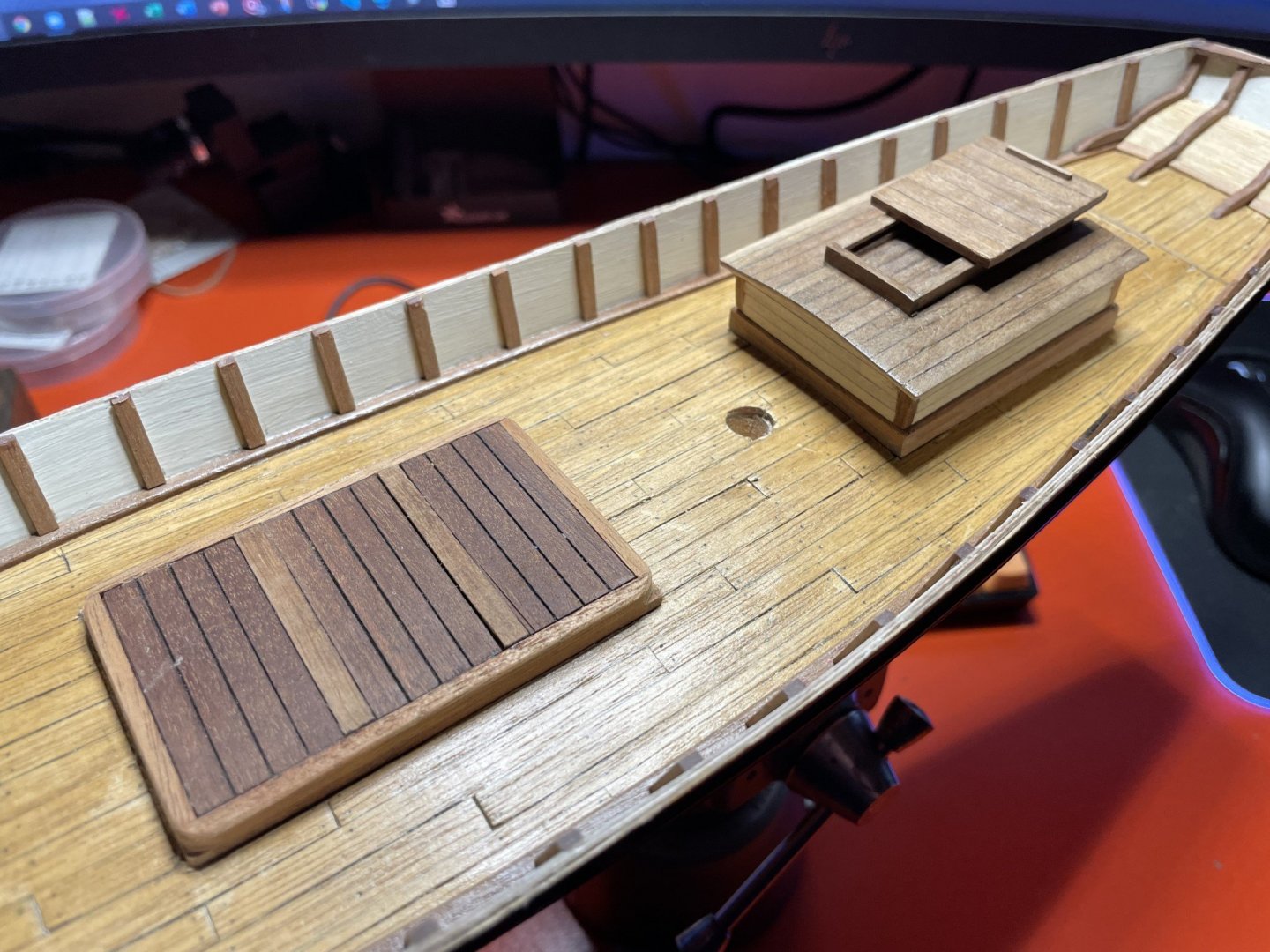
I've done a bit of this and that the last week, mostly focusing on finishing some of the deck furniture, the caprail, a hole for the rudder, tapering the masts and bowsprit, plus working out a new arrangement for how the bowsprit is mounted. First, I fixed up and reattached the caprail, which helps bring it together well. Next, I finished up the aft small deck house / companionway as well as the forward hatch cover. The original kit had a second forward deck house / companionway as well, but it seemed a bit odd having two, so it became a hatch. Finishing these came down to putting some little metal fixtures on them such as the lift eyes eyes, as well as the small vent stack. I did have the original cheap metal cast stack from the kit, but in the last 40 years it disintegrated and was crumbling. So what I did was build a new one using 1/8" brass tubing. For the bend, I made a series of thin slices almost 3/4 the way through along the bend area, then bent it such that the saw cut kerfs closed and left a nice curve. Then I used solder to fill in the gaps, and cleaned it all up with a file. Here's a quick sketch showing the concept... Then I made a small ring of brass wire, and hammered it flat into a disk for the base, then soldered it on as well. To make it black, I just coloring it with a black marker then applied some matte varnish. I've got some Birchwood Casey Brass Black on order, but figured this would work - plus be better on the soldered areas. Next up the tapering the masts and bowsprit. I had two 8mm dowels to be tapered from 8 down to 4mm for the masts, plus the bowsprit to taper from 6mm to 3mm. I did the tapering by mounting the dowels in my drill press, using a small 608 bearing as a pivot to steady the longer masts. Here's the basic setup, as well as how the shorter bowsprit was just mounted as-is with no end steady. Tapering was done with a hand file as well as 80 grit sandpaper for the initial smoothing. I also worked out a mount for the bowsprit, but I'm going to put that into a separate post to not let this one get too long.


- 44 replies
-
- 1
-
-
- first build
- Artesian Latina
- (and 1 more)
-
I bet a lot of us do that I don't speak Spanish but I've had a few on with a Spanish narrator in the background - I forget his name but he has a good voice. And there is something about the OcCre ENDURANCE video music that is just so calming... Your videos have this great mix of upbeat music with the sound of sanding and tools that's also good. It's like you're in a workshop where others are also working on their models, and you get to hear the sounds and look over now and then to see what they are doing.
- 156 replies
-
- 1
-
-
- marisstella
- marisstella model ship kits
- (and 4 more)
-
I've got an old (late 40's early 50's) Atlas benchtop drill press that's a really good solid workhorse. It's solid, heavy, and runs very smoothly - not vibrating like the cheap stuff one buys nowdays. I'd like to be able to mill smaller pieces of wood, and I'd like to toss out my thoughts here and see what the communal brain thinks. As a preface, I've used a massive Bridgeport mill before and know how they work, etc. so understand the whole milling machine concept. I would not mind buying a mini mill, but in the spirit of "not yet another tool", I'd like to think about using my drill press for the job. My "I haven't hit buy yet" plan is to get a small X/Y table that I can attach to the drill press table. It has to be good, very smooth, easy to operate. I don't want slop or play in the X/Y movement. Then buy a nice small mill vice to attach to it, and possibly also a tilt/swivel base as well. I know that drill presses aren't meant for that sideways pressure with bearing arrangements and all that. And the chuck might not be as ideal as a regular collet setup. But I'm talking about milling wood in small amounts, not metal. Crazy idea? Not? PS It's dawned on me that if I do by an X/Y table, I can always buy a mini-mill later and use said table...
-
I quite enjoyed the rudder video today. I often have one of your videos or some by other builders playing in the background when I’m working on my model. A question. Did you put any glue on the pins into the hull for the pintles and gudgeons? Or on the pintles and gudgeons themselves?
- 156 replies
-
- 1
-
-
- marisstella
- marisstella model ship kits
- (and 4 more)
-
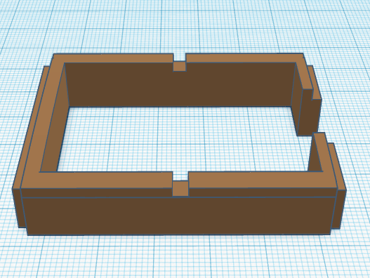
To be clear, it's not at all appropriate for the kinds of sculpted details I'm seeing here, but for really basic stuff (like jigs and non-ship parts), I use Tinkercad. It's a simple free, web based system for solids modeling that Autodesk has.
-
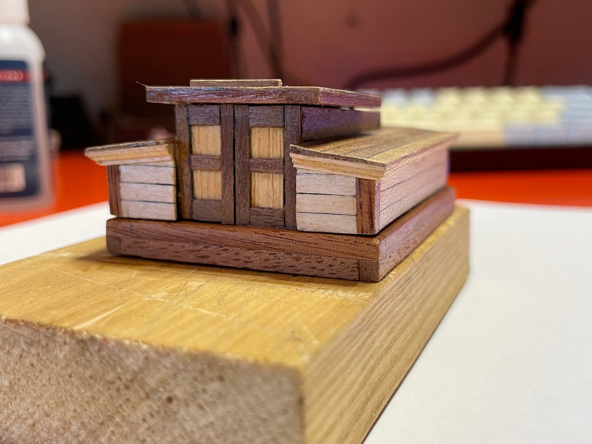
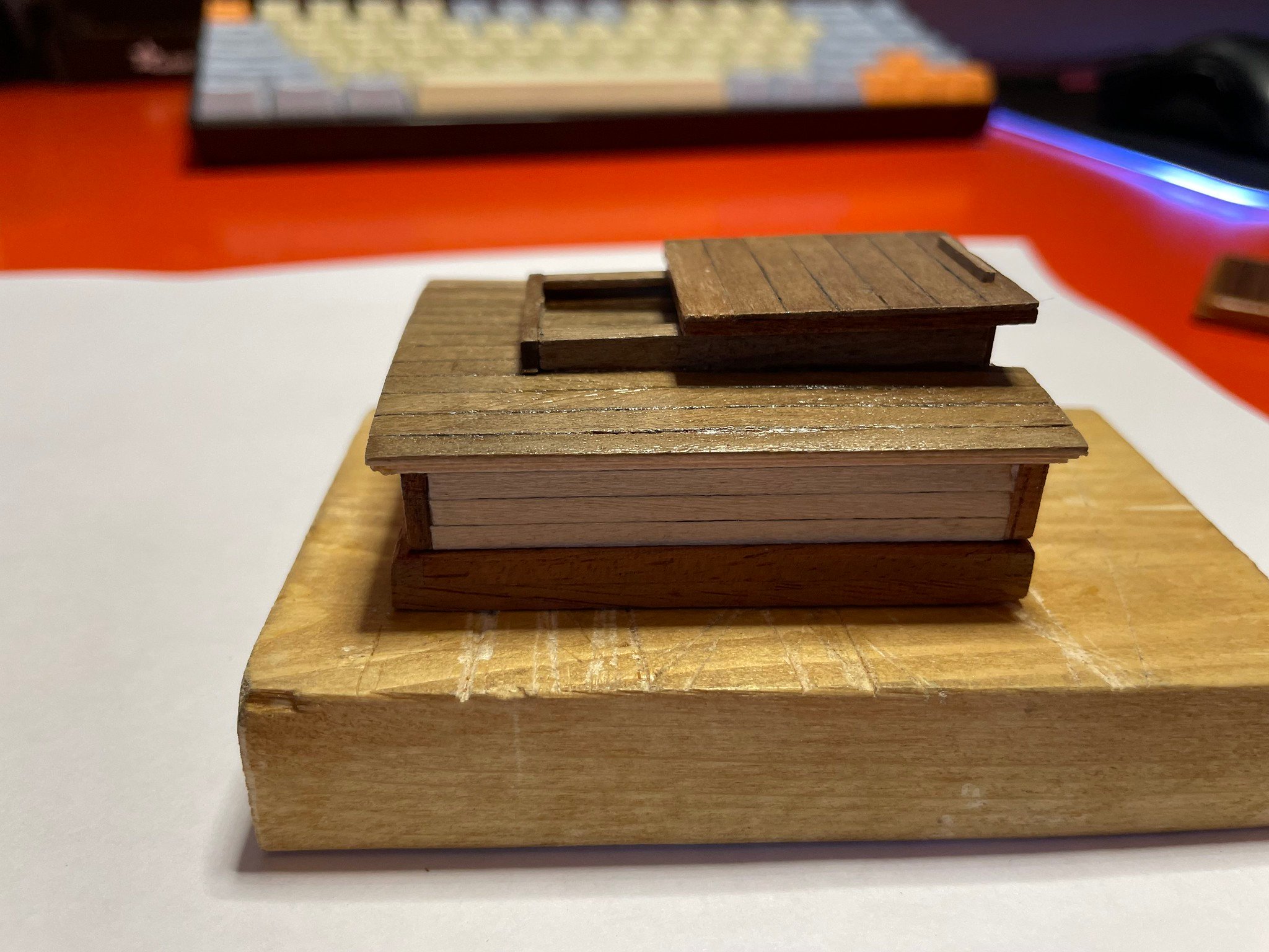
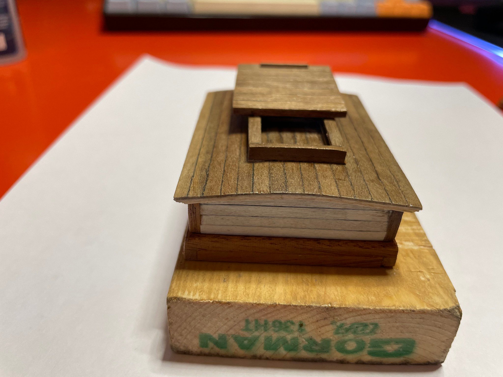
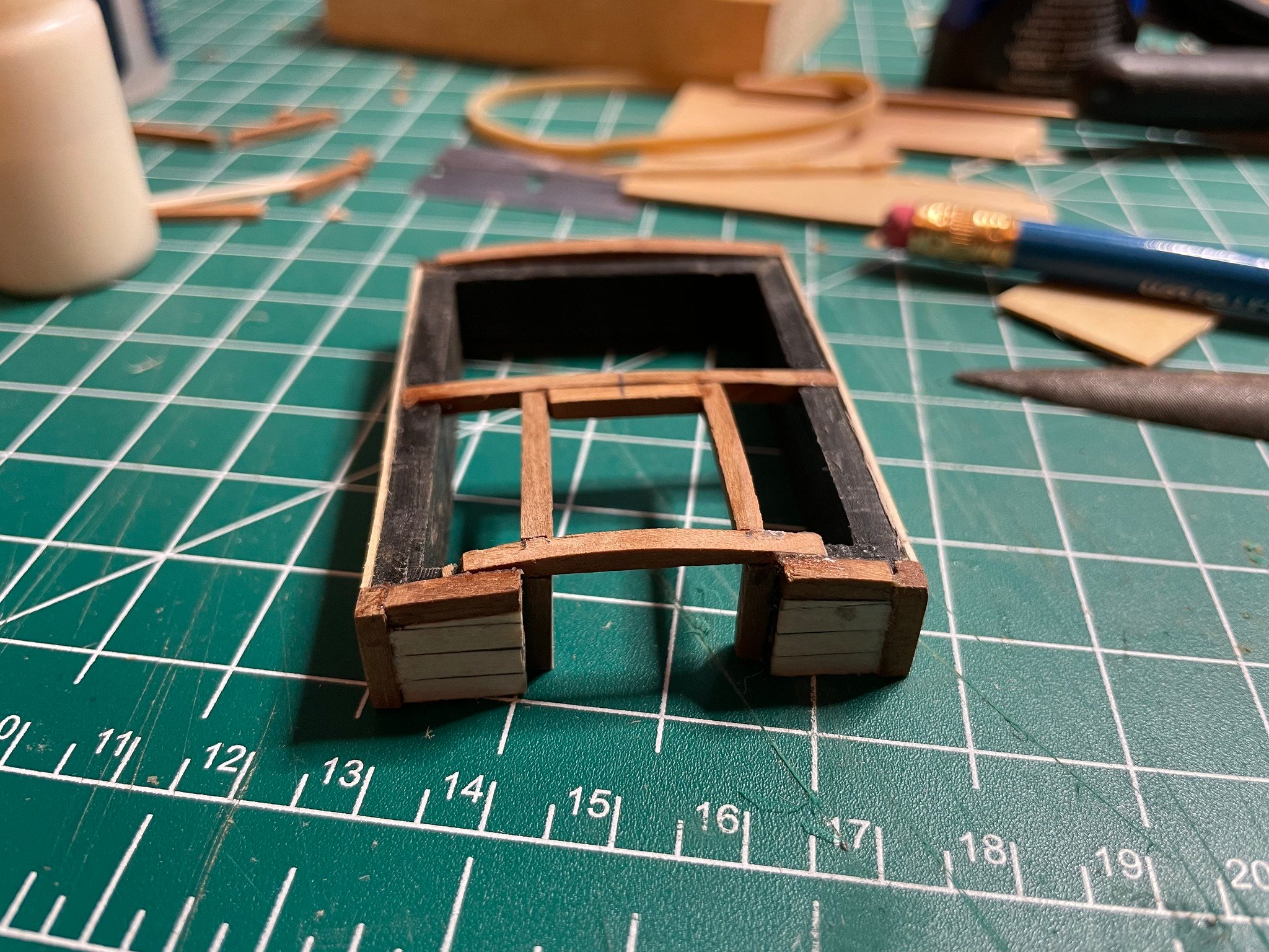
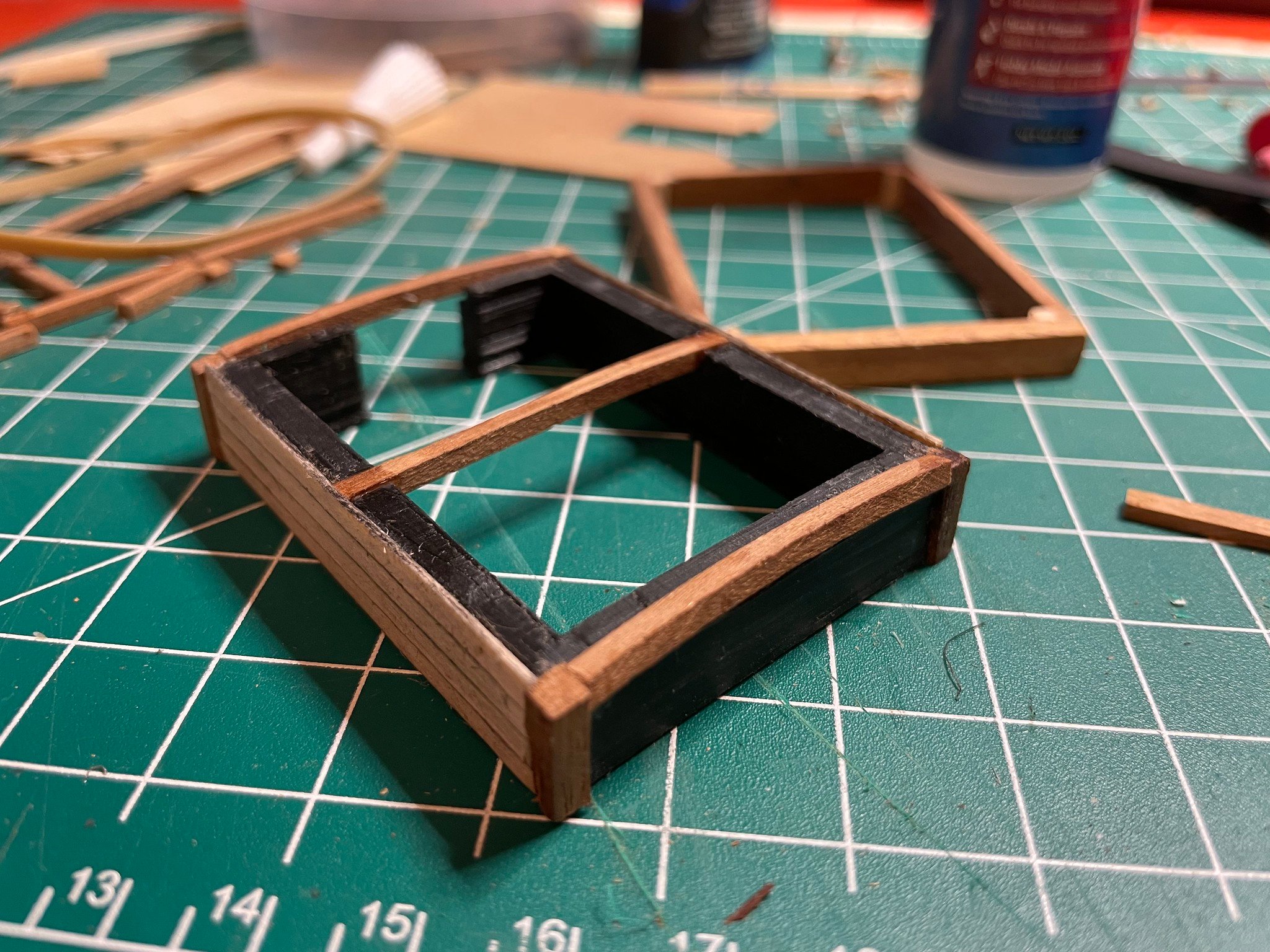
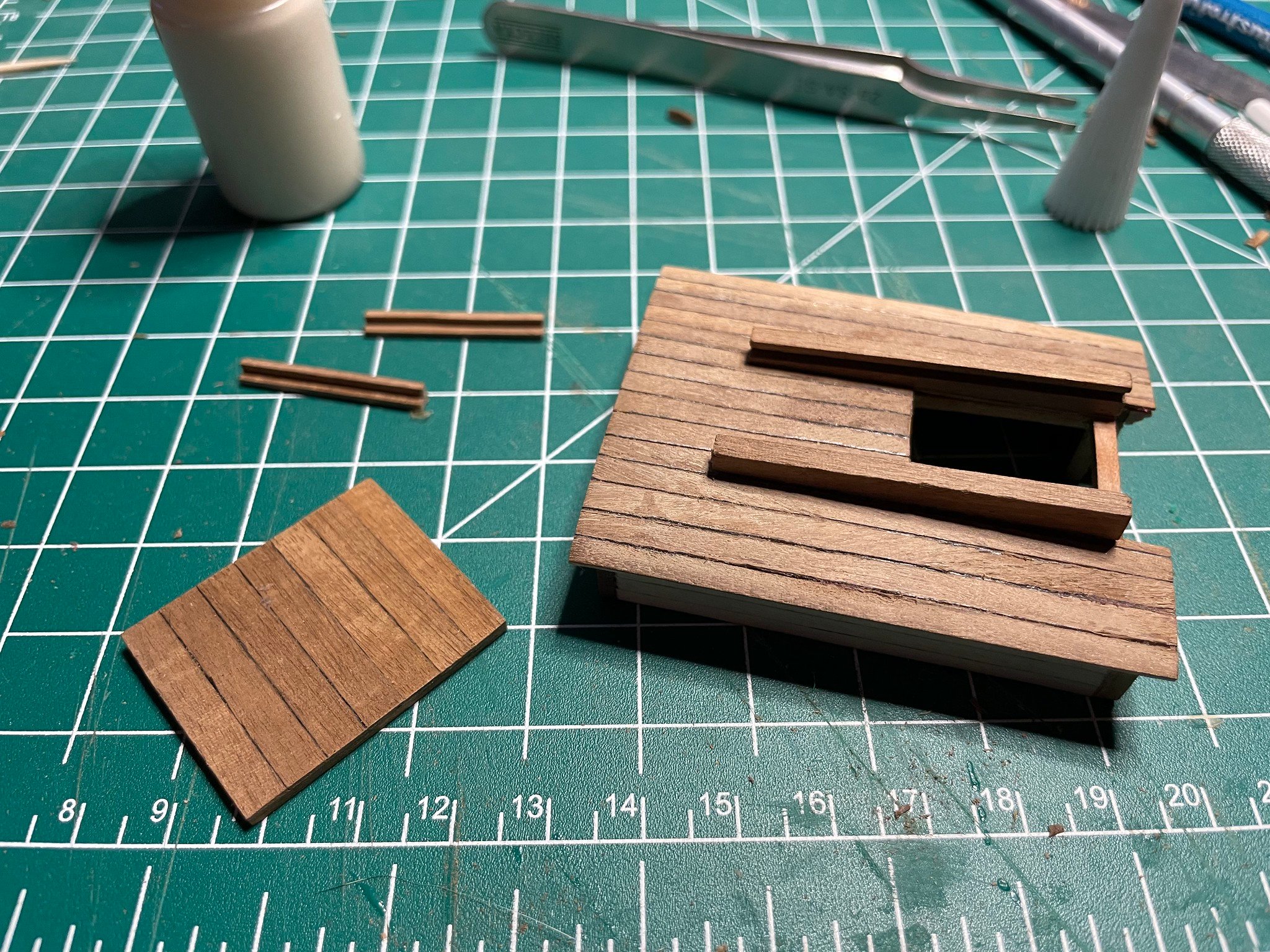
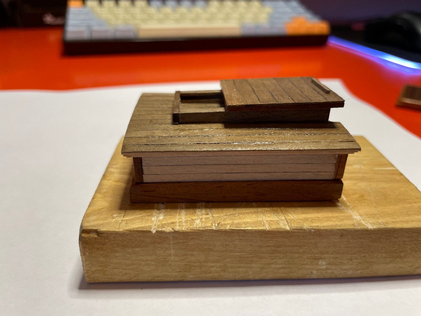
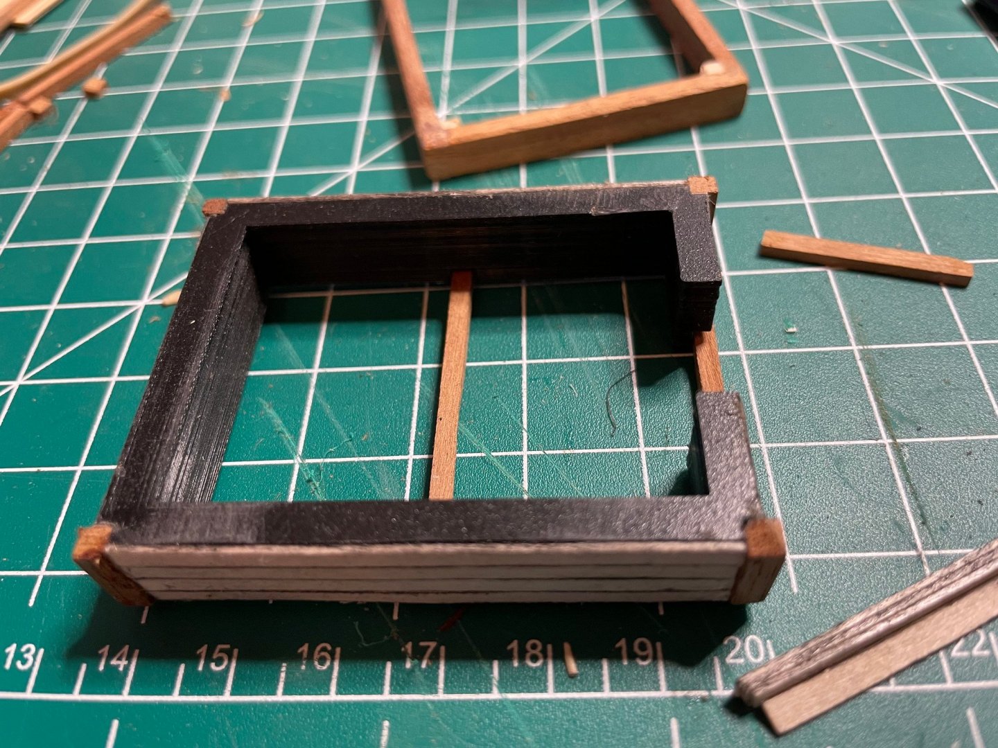
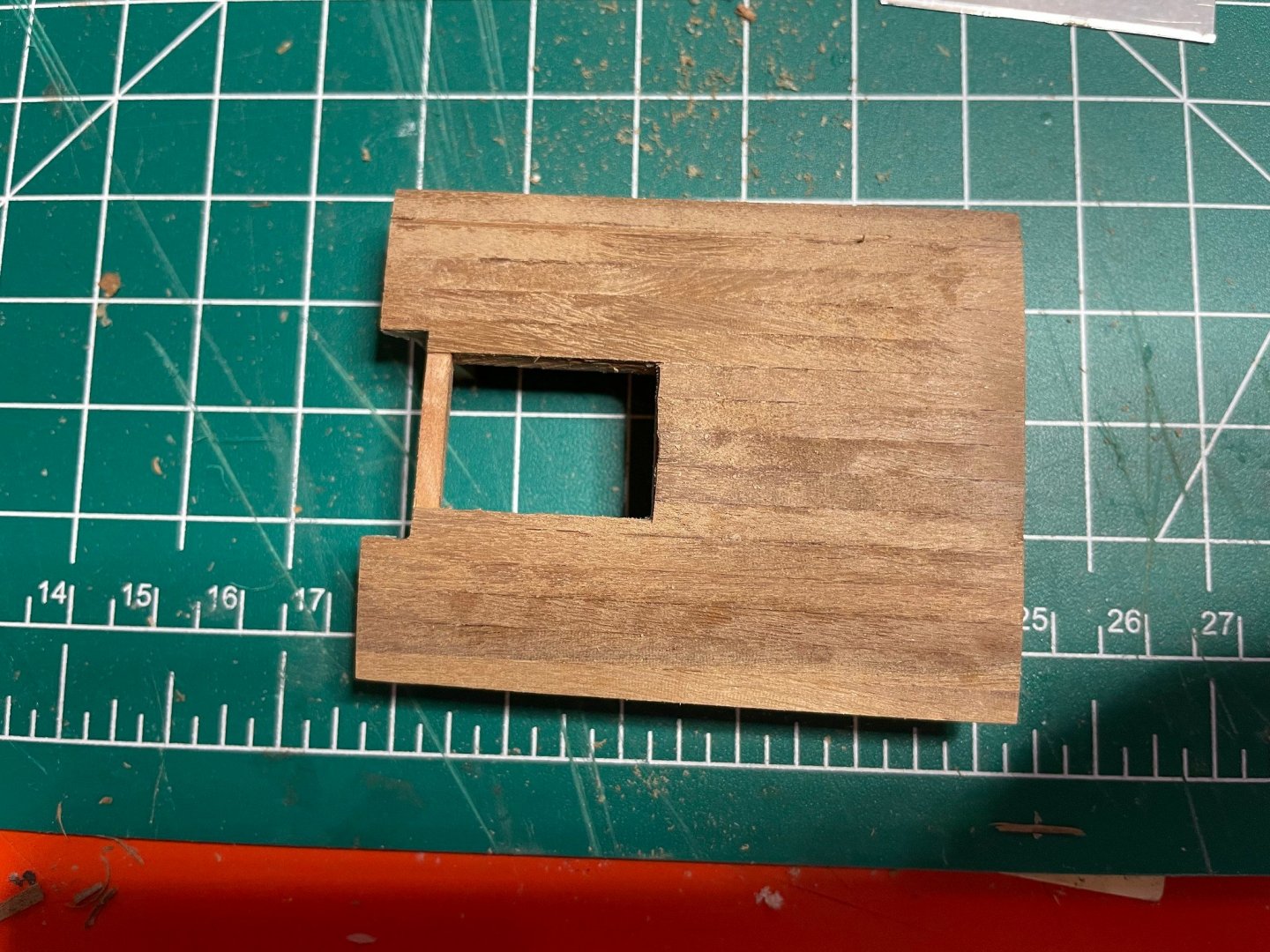
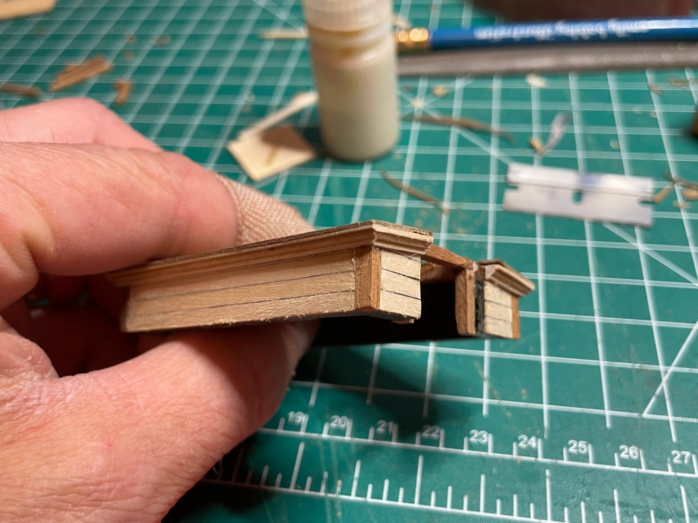
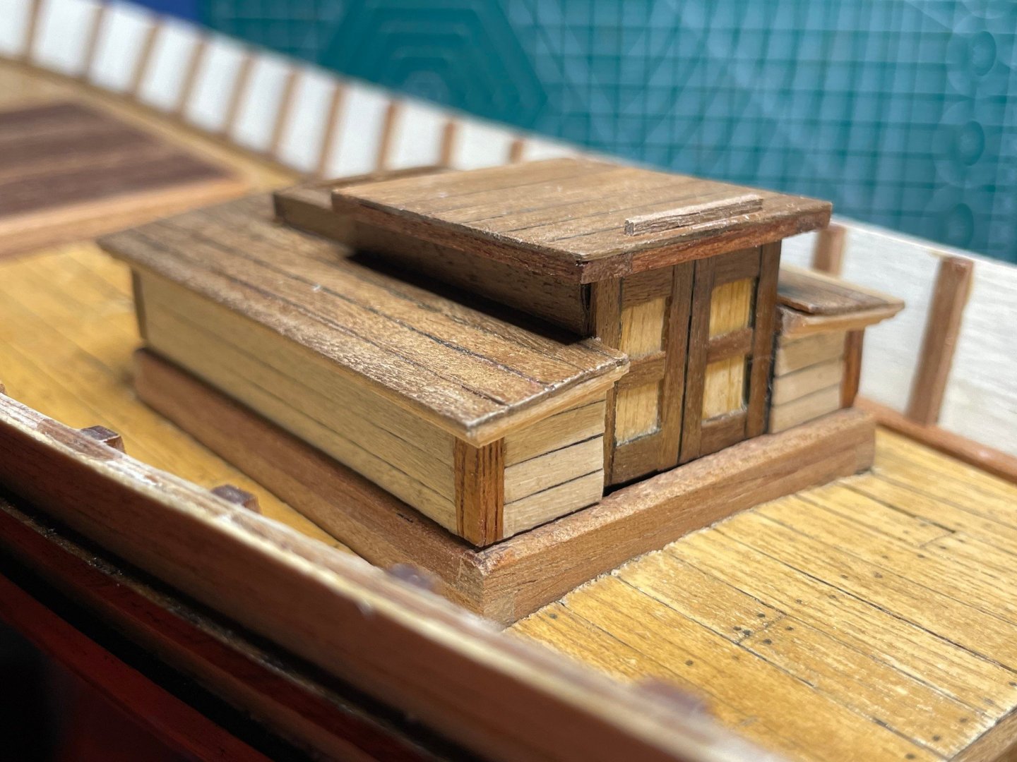
Here's what I ended up creating. I'll start with how it looks completed... I went with corner posts, as well as horizontal siding, but deviated in a rather modern direction for the actual internal framing. I ended up 3D printing an inner plastic form that holds it all together. The form has cutouts on the corner for the posts, as well as cutouts on top to hold bent roof rafters. Siding is just glued directly to the plastic of the form. Originally I considered using it as a jig for the framing, but realized it did a really good job of making the whole thing solid and sturdy. Here's the form with the posts glued on, as well as siding glued directly to the form. Here's a view of the bottom. Additional wood was used to outline the opening accessible when the hatch is slid back.


-
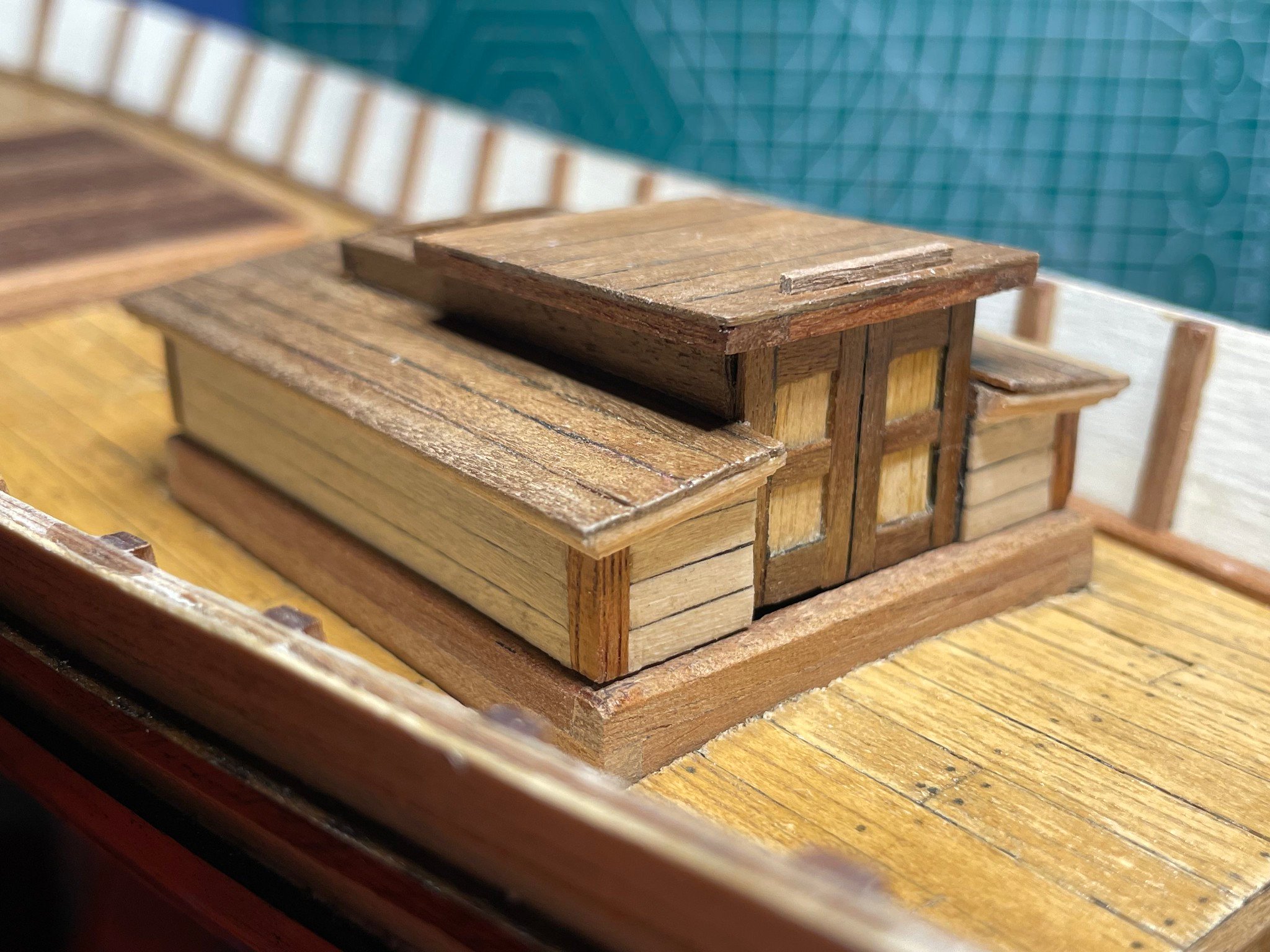
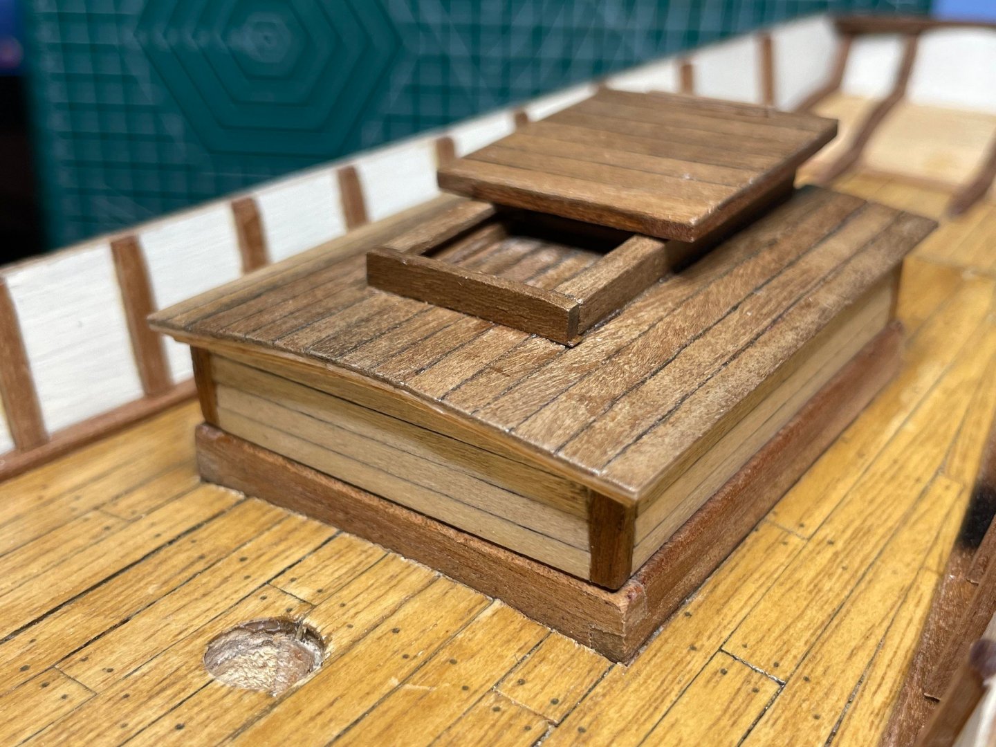
Tonight's post is about building the little aft companionway. Continuing the spirit of using this model as a bit of an experiment, I tried out a new approach to building it. I didn't much want to just glue together the ill-fitting pieces of plywood and cover them with thin strips. I wanted something a bit more "real" looking that had a sense of how it was actually framed or constructed. Originally, I tried actually building a frame for the main structure using 1/8" square stock, but found it very hard to both ensure everything was correctly aligned, but also make sure the whole structure was solid and strong. I started thinking of making a jig of sorts to help me align the corner posts and curved ceiling rafters, but then it dawned on me I could just 3D print a jig, and literally glue everything to it, and keep it on the inside. So I came up with this design (here in TinkerCAD) that I 3D printed in PLA on my Ender 3 Pro. It has the basic interior dimensions of the cabin, with a notch on each corner where vertical posts go. The notches are smaller than the actual stock used for the posts so that they would stay proud. Running side to side on the top, there are also notches where I can put down bent pieces of 1/8" stock to defined curved roof rafters. Then on the right side is the opening for the doorway. Here are some pictures of the construction, where I first glued the corner posts the 3D printed part (in black), the horizontal siding, companionway entrance framing, and curved roof rafters. The last picture of the 3 shows the bottom, and how the 3D printed framework is holding it all together. In the end I just sanded the posts down flush with the siding, which worked out a lot better for the next step, which was adding crown moulding for under the edge of the roof. See this post on how I made it. Then I glued thin narrow strips meant for the original construction to the roof, using the curved rafters as gluing points. This is where I found out I should have had 2-3 more rafters to have more gluing points. Then the tracks for the sliding hatch, and a hatch door. You can also see here that I scribed and marked the roof board joints with pencil, which made it look less like a large sheet of mahogany plywood for a roof. Finally a little strip across the back to keep the hatch from sliding off the tracks, and a little door (that still needs handles). Then some fine sanding and a few coats of satin varnish with sanding between. In both these pictures I've just got it setting on the coaming frame - not glued down yet. Oof, that gap under the door... You might notice here I took the previously pictured caprail off. I didn't like the way it fit, and am going to reattach it at some point.


- 44 replies
-
- 3
-
-
- first build
- Artesian Latina
- (and 1 more)
-
Thanks all. This build is definitely one for experimentation and exploration. I came up with a pretty decent approach to building the the companionway that I’m going to add to my build long before long. A hint of it at Just need to finish that top sliding section.
-
Too late! Most all the Dover Press books now, Longridges Anatomy of Nelson’s Ships on the way. Very tempted by the Anscherl TFFM series.
-
@Bob Cleek thanks for the long thoughtful reply.
-
Trust me I got it bad already So many things on this kit are cheaply fake it’s driving me nuts. And at the same time I look at the faked shape of things and think, “OK but why is it shaped like that? What is the underlying structure that makes it in that form?” But it’s a good learning opportunity and a good chance to make mistakes. Longer term I want to scratch build something. I have a huge personal stash of Alaskan Yellow Cedar, plus access to both a laser cutter as well as bench top milling machine to do some precise shaping.


.jpg.7501dd093c3412f342a26bdcd0191058.jpg)