HOLIDAY DONATION DRIVE - SUPPORT MSW - DO YOUR PART TO KEEP THIS GREAT FORUM GOING! (89 donations so far out of 49,000 members - C'mon guys!)
×


GDM67
-
Posts
103 -
Joined
-
Last visited
Content Type
Profiles
Forums
Gallery
Events
Everything posted by GDM67
-
Hi Ed, Thanks for the words of encouragement! Building a ship plank by plank and bolt by bolt is definitely a new challenge for me and comes with a steep learning curve. That being said, its very exciting. I agree with the template use - I now paste them to both sides of many pieces so I can cut the proper angle. This comes in handy for cutting the footing of frames. Best, G
-
Great work on your boxing joints. I just did a few attempts... for one ship, so I fully appreciate your efforts. G
-
Have you considered adding those copper nails to the build in some fashion? While at the same time preserving them in their intact form. Again, great archeology and build. Very enjoyable to read. Gary
-
I recall an article within the last year or so in the NRG mag on the subject by William Sproul. Gary
-
Hi Ed and Druxey, Thanks for your follow up to my glue question. I will keep trying... Ed, I think you are right about the binding agent. This is exactly what I think happened. Back to building. I have done some (more like a lot of) rework on the Naiad - I was not a fan of the knee of head and a few other areas, so I went back and redid all of this, ok, everything... It caused a lot of pain and as you can imagine, I was not motivated to take photos, but in the end, I am very satisfied with the outcome and the decision. Hey, if I am going to stare at this project for the next four years, its got to be pleasing to my eye. The biggest issue was that I had drastically undercut the bow and made the entry much too fine. I tried to overcome this as I placed the forward cant frames, but simply found that it altered the beam of the ship drastically. So over I started. Needless to say, there was a day of depression... 33 hours later, here we are with a new keel, stern deadwood and head of knee. I find that I am much smarter the second time around. Some lessons I have learned on this build: 1. Chisel instead of #11 blade (too late for my left index finger...) 2. File instead of sanding stick 3. Razor blade instead of sandpaper 4. Micrometer that measures thousandths, not hundredths 5. Successive pieces glued together have a cumulative affect on the size of the subassembly. Constantly refer back to the plans and templates - adjust accordingly. 6. Keep a "Ships Daily Log". Even if there are doldrums, record in it each day. Hey, they had to do it at sea, so why not do it at home??? 7. Don't final sand or final shape a piece during the subassembly phase. The risk of undercutting or misshapaing is significant. By waiting to do this, it will help to bring the entire project together as one. Next up is the infamous Bollard Timbers and stem rabbet... Wish me luck. G
-
Ed, can you share a little more detail on the black glue and perhaps a photo? I have tried it several times, first with a powdered acrylic and second with a acrylic pigment paint. Both times, the glue congealed instantly. I think that I might have invented a new silly putty/crazy glue concoction! It ruined my wifes mortar and pestle... All in the name of ship building What exactly is artist pigment? My local art store tries to sell me a single pigmented black acrylic paint tube. Thanks! G
-
Ed, you have created a monster... Between your books and those of David Antscherl and Greg Herbert, I will never look at scale ship building (thats what I call this thing) in the same light again. Thank you! G
-
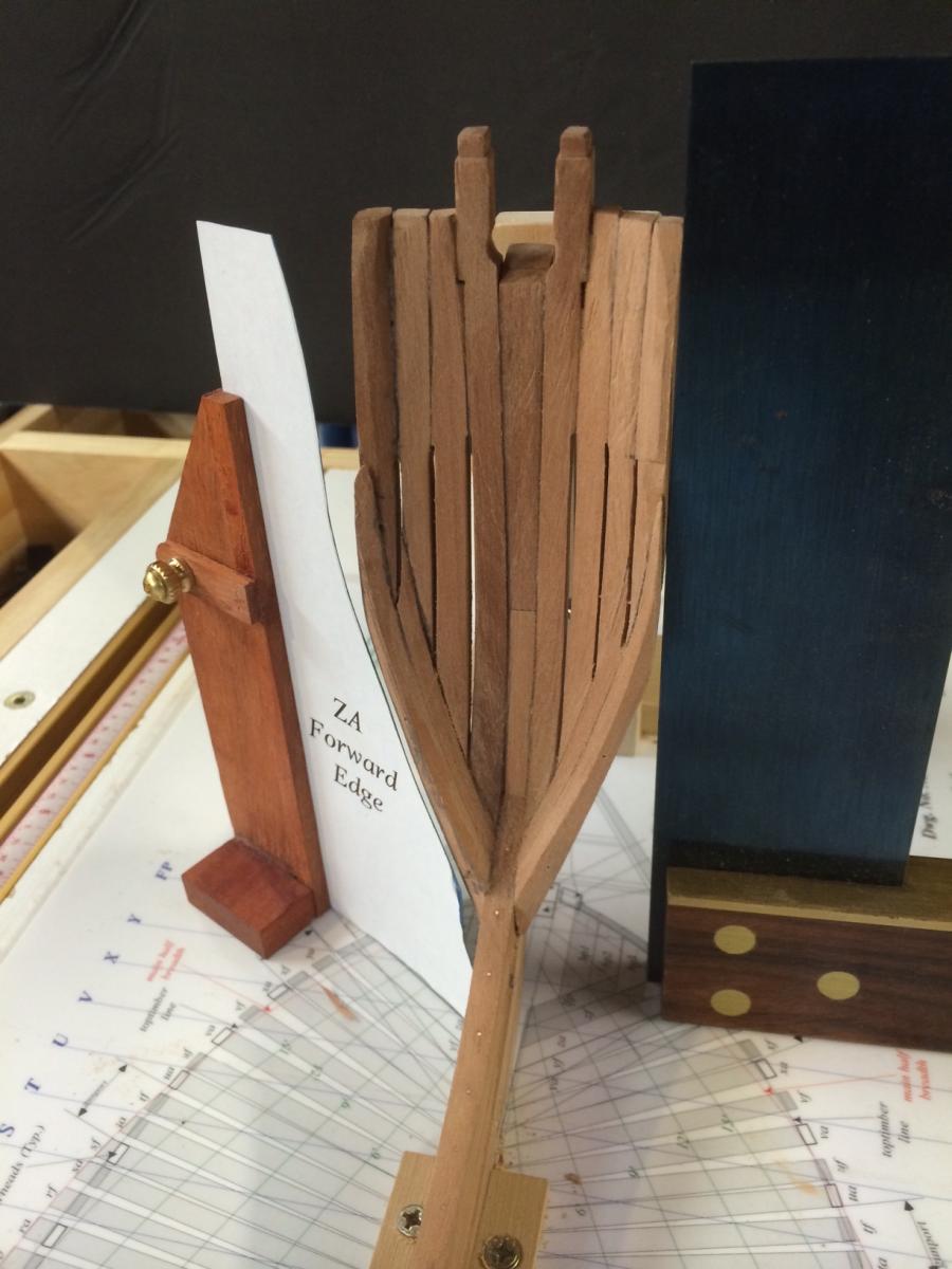
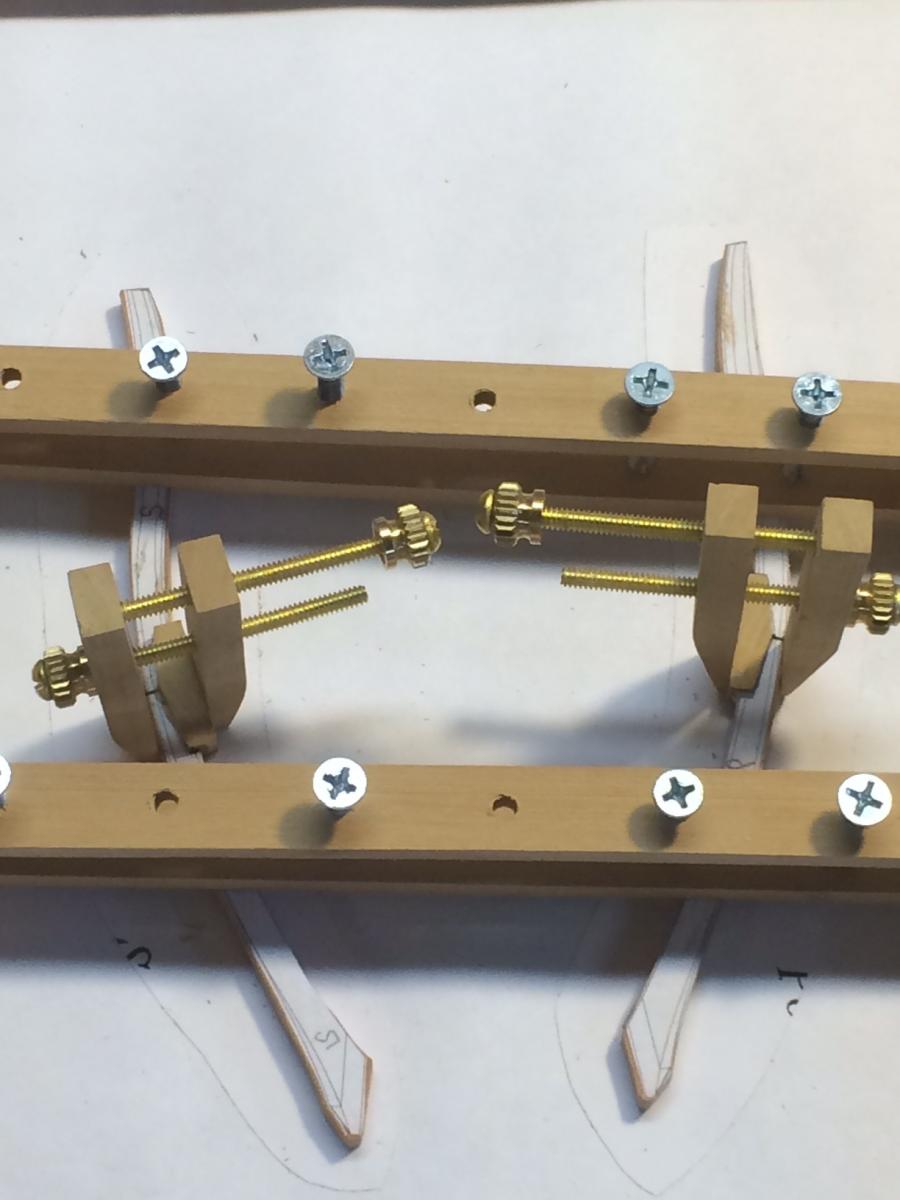
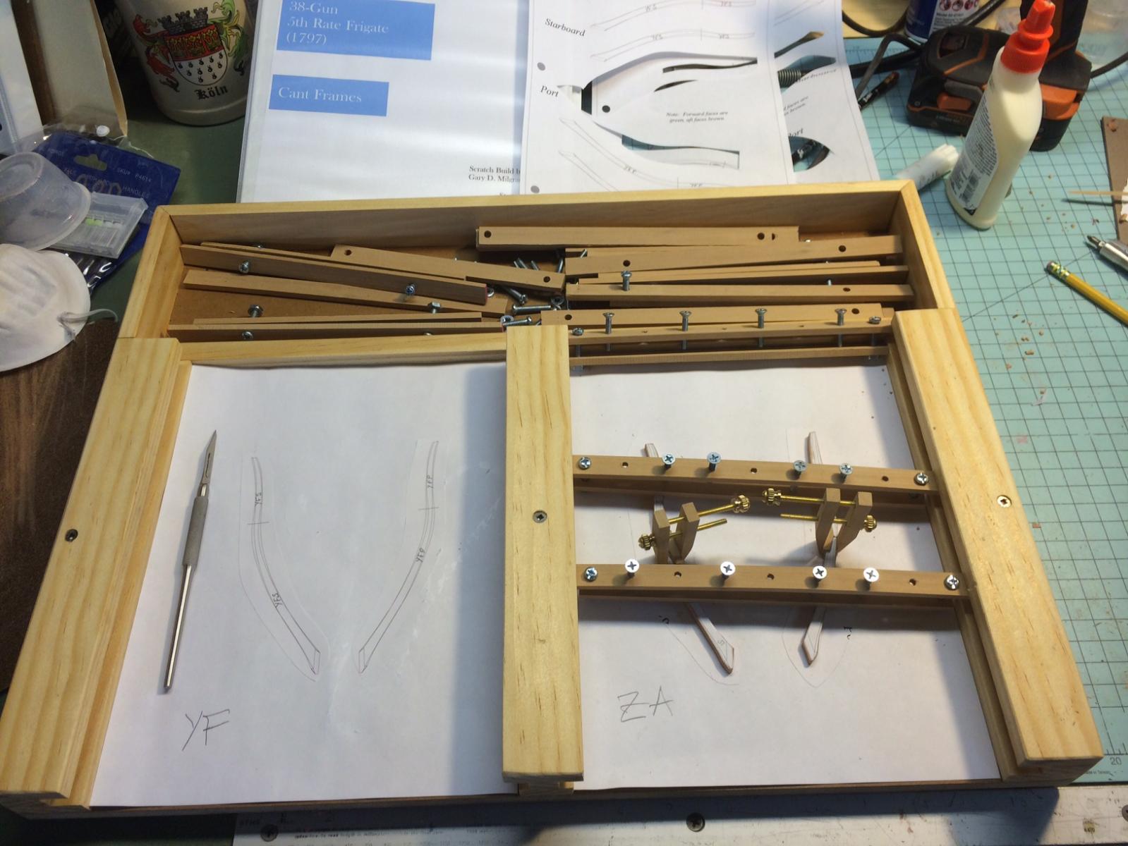
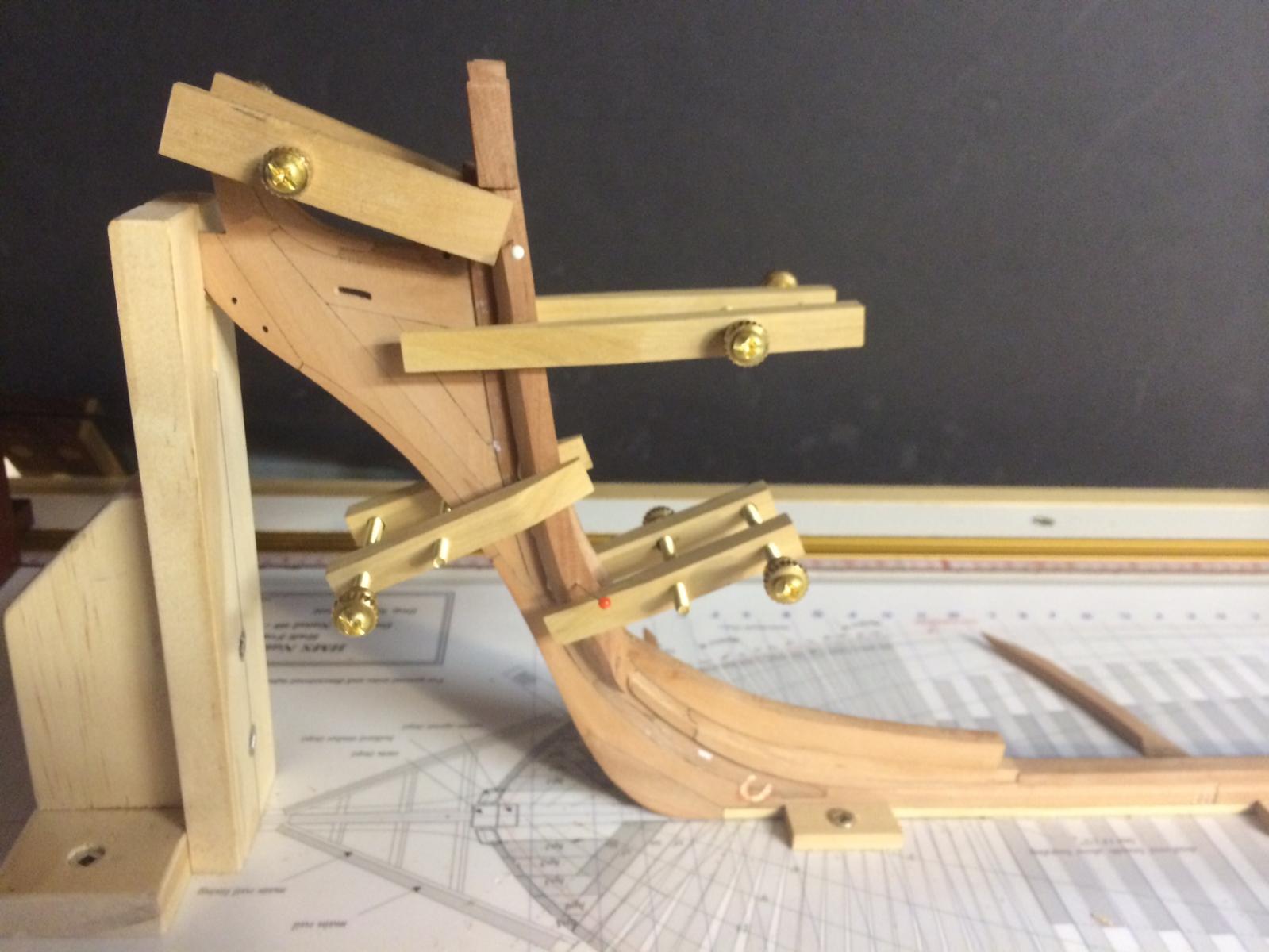
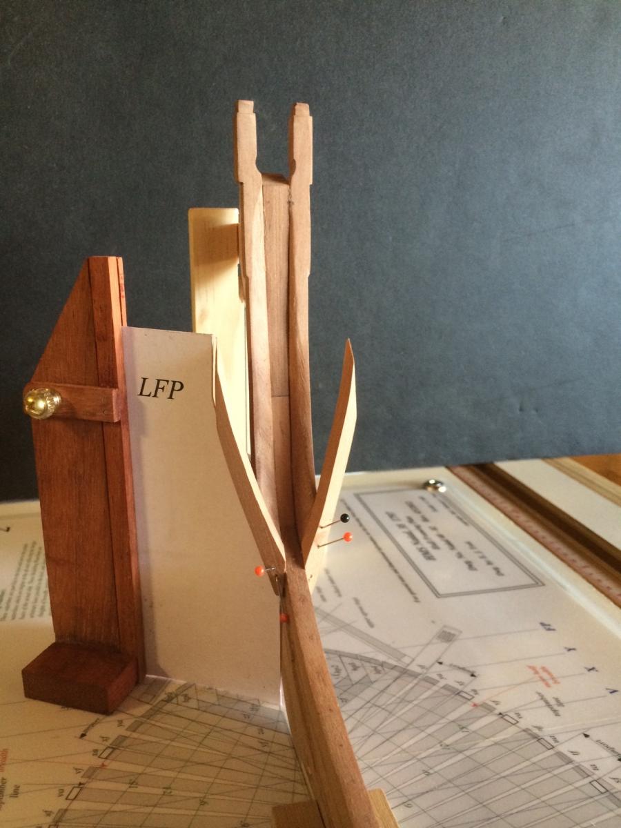
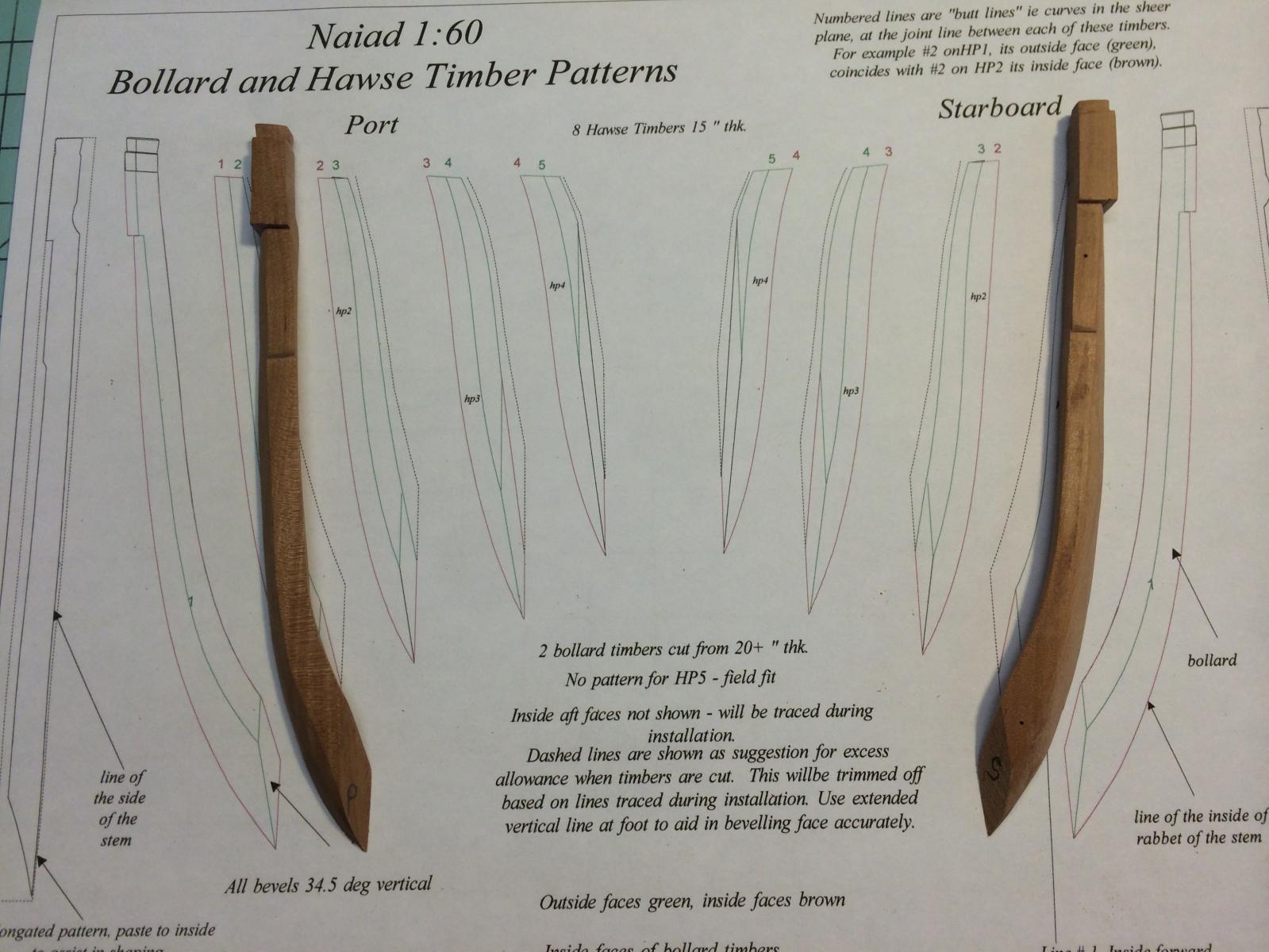
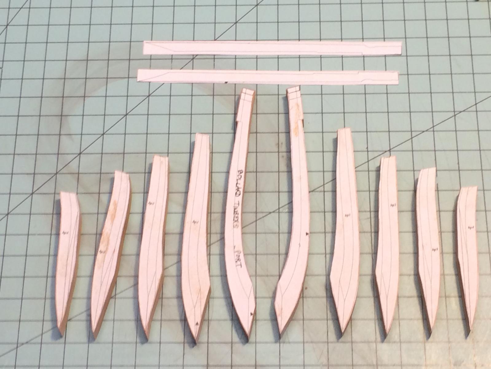
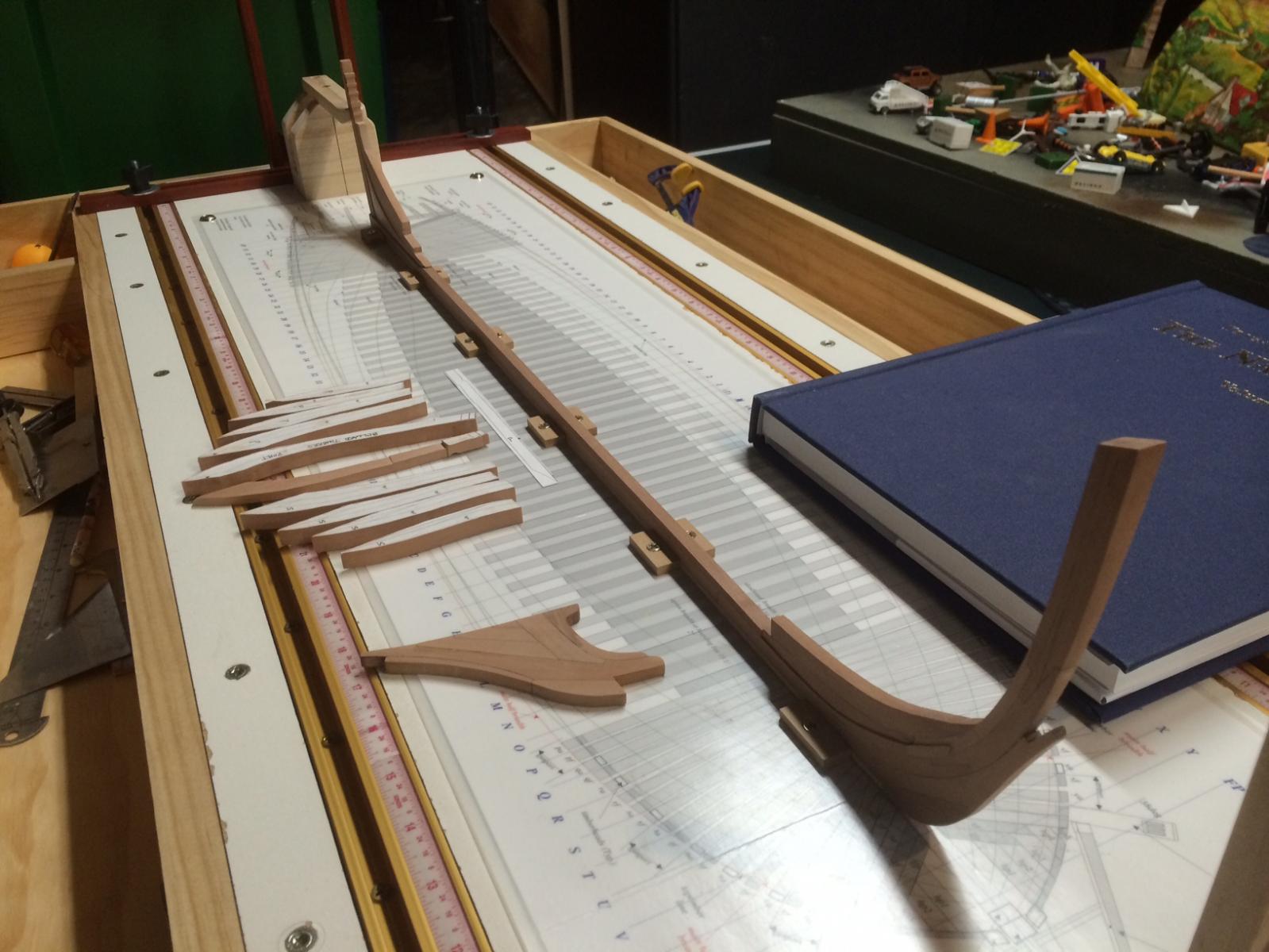
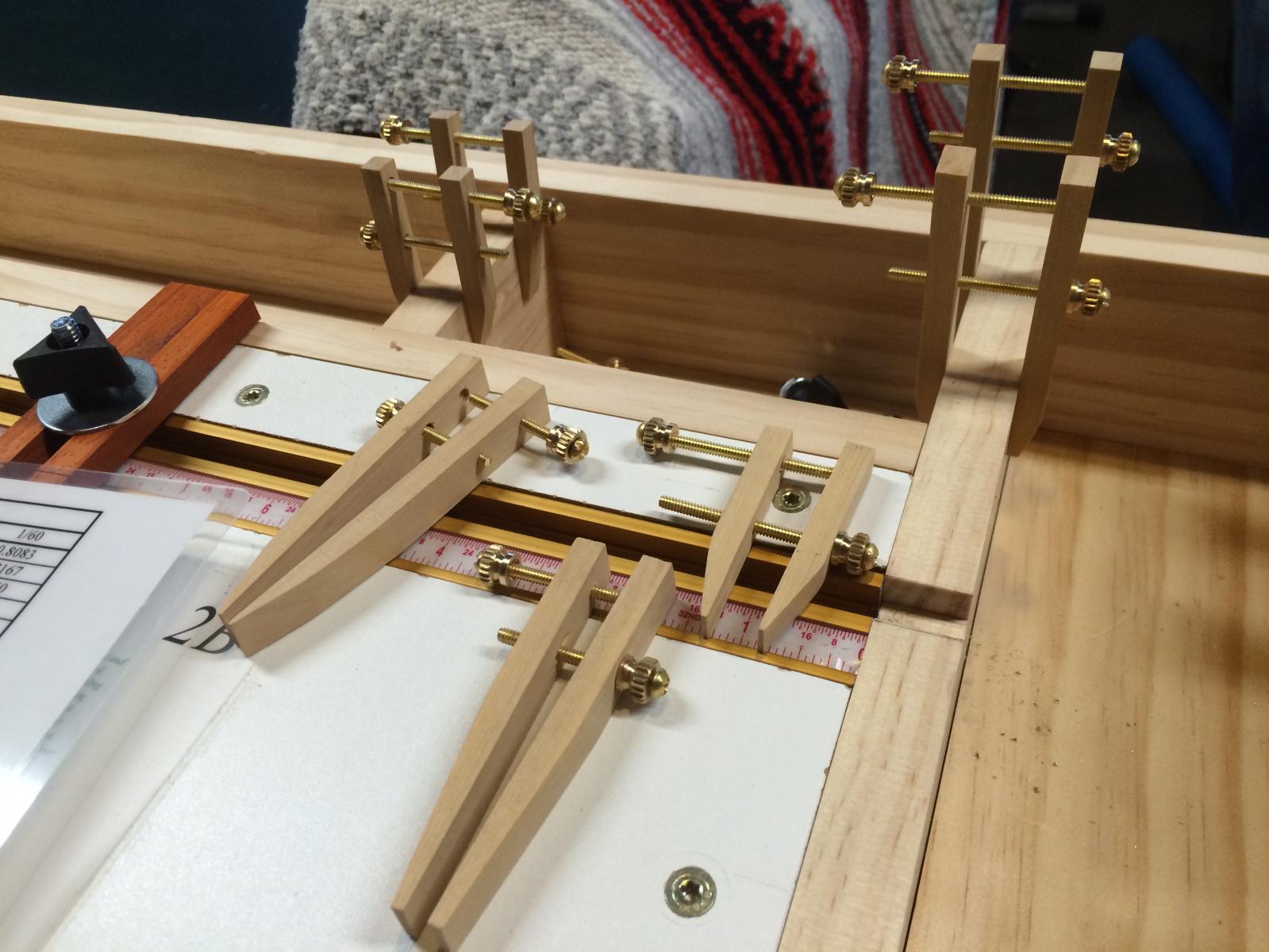
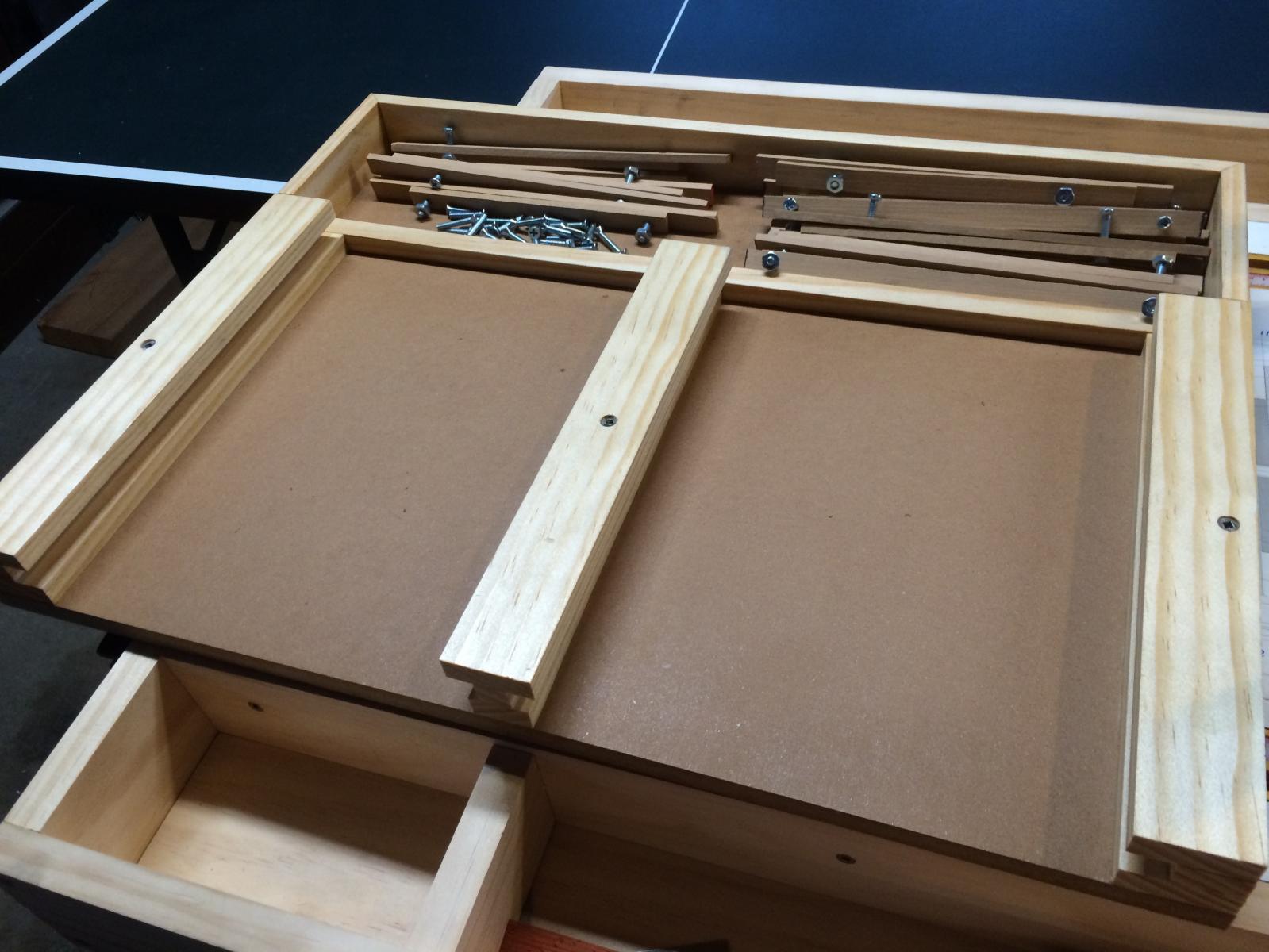
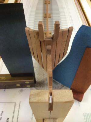
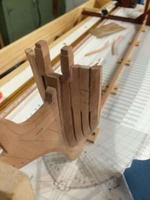
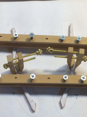
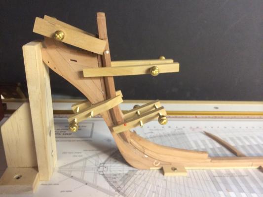
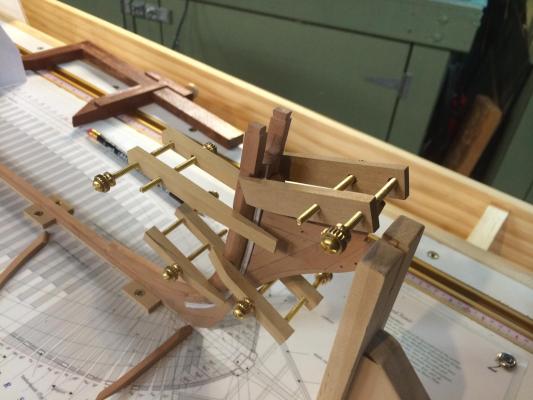
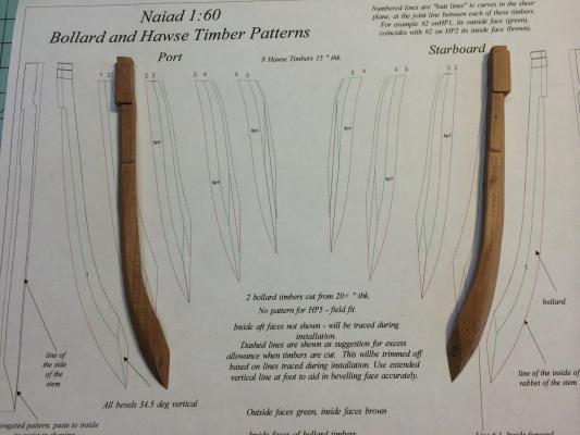
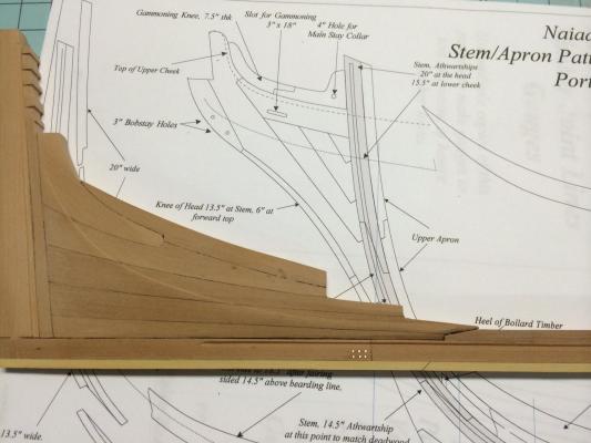
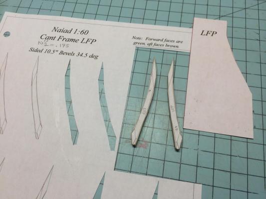
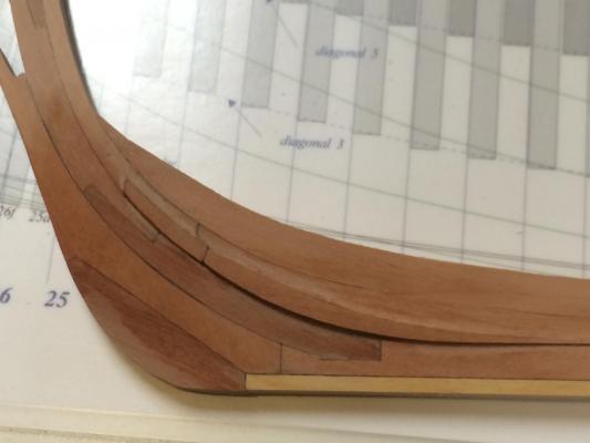
Work on the Hawse pieces progresses, albeit at a slow pace. Please note that there is a lot of finishing work to be done. At this stage, its all chisel, rasp, 60-grit sandpaper... But I thought I would show the worts and all... Shown here is the Bollard Timber fayed to the stem with the roughed in detail of the knighthead. Also shown are hawse pieces 1-3. Note the air gaps. These should be 2” wide and still need to be worked. The template is for the first full cant frame (ZA). Once that is installed, I can go back and fit hawse pieces 4 and 5. I had great difficulty getting the hawse pieces right. I found that field fitting them was the best approach for me, paying close attention to the templates as well as the base drawing. I have now found myself obsessing over a couple of hundredths of an inch when it comes to the drawings. Here is the inside view of the hawse pieces. Note the second full under timber (really a short cant frame). This needs to be perpendicular to the base of the keel. Again, this is all roughed in, using a rasp and chisels. Polishing work will come once the full shape of the bow has been established. THERE IS A GREAT OPPORTUNITY HERE TO RUIN THE SHAPE OF THE HULL AND MAKE THE ENTRY TOO FINE BY UNDERCUT THE ENTIRE BOW STRUCTURE IF YOU GO TOO FAR…. DON’T BE TEMPTED TO FINISH IT TOO MUCH. (This is a temptation for us perfectionists – which by definition is exactly who we are as scale ship builders…) Here is the framing jig that Ed Tosti wrote of in the book. I just love this jig! I made mine a double jig and have tapped all the holes in the cross bars. They are set one inch appart. I have blank bars in the storage tray above that I will tap as I move along. I plan to use this for future builds as well. Now that I have started this style of ship build, I dont think I will build another ship any other way. Its not enough to simply cut out the frame pieces and place chocks between them. The jig allows you to clamp each piece down and then orient them so they match the template. I think you can get into trouble here if you don’t use a jig like this. The cumulative misalignment of a few frames can spell disaster. Above the jig in the photo is a small binder that I made for the cant frames. I have a similar binder for the square frames, scantlings, etc. Keeping things organized is a must for a build like this. There are literally hundreds, of frame pieces to make and each one is an opportunity for misalignment… A close up of the jig in action. The cross bars hold the piece down, while the small clamps hold the chock to the frame at the proper angle. The other side of the chock was glued to its frame in a previous step. Did I mention that I just love this jig? The time it took to build is paying off handsomely. Down below are the first two full cant frames for the bow. Detailing work still needs to be done here. The foot of each needs to be fine tuned. I have found that using a chisel works better for me than the grinder in establishing the foot angle. I have a far too heavy hand at the grinder and this step requires delicacy. I also attach the pattern to both sides of at the footing. This helps me visualize the angle better. The chocks are made from Boxwood, while the frames are pear. Next is to attach the first full cant frame, then to place hawse timbers 4 and 5. I will then place a few more cant frames before doing a semi-final shaping and clean up of the structure. Best, Gary


-
Paul, I really nice build and I greatly appreciate the archeological details as well. More photos please... Your hawse pieces are superbly done! Gary
-
Hi All, thanks for the get well wishes. Despite having 5 sutures in my left index finger, I was able to install Hawse timber #2 tonight. Photos next week. To answer a few questions: The clamps were Ed's design and I love them. I use the typical colored plastic spring clamps for mock up and then fit these clamps for final glue up. I like being able to adjust the pressure of the clamp as required. Ed also shows a clamp that pivots for irregular angled pieces. I plan to make those soon. The foremost cant frame was installed per the book instructions and a great recommendation it is. I relied on this frame for the field fit of the hawse timber feet. As for the pin holes, right now, they won't show because of pieces that will glue over them, but in areas that they do show, I will try to place them where bolt holes will be placed. Thanks for all the interest. As I said before, it's very rewarding. Gary
-
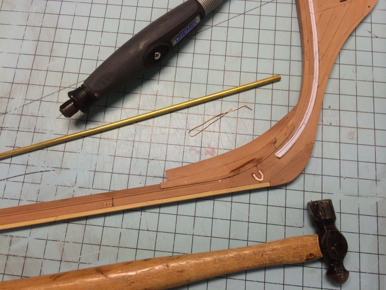
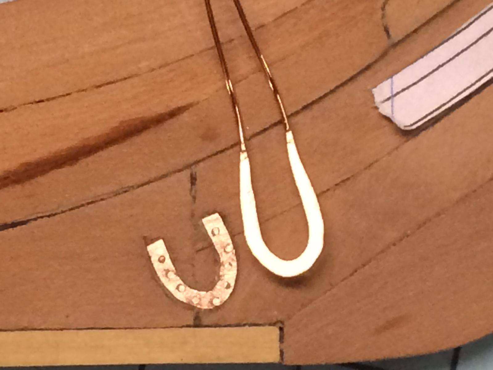
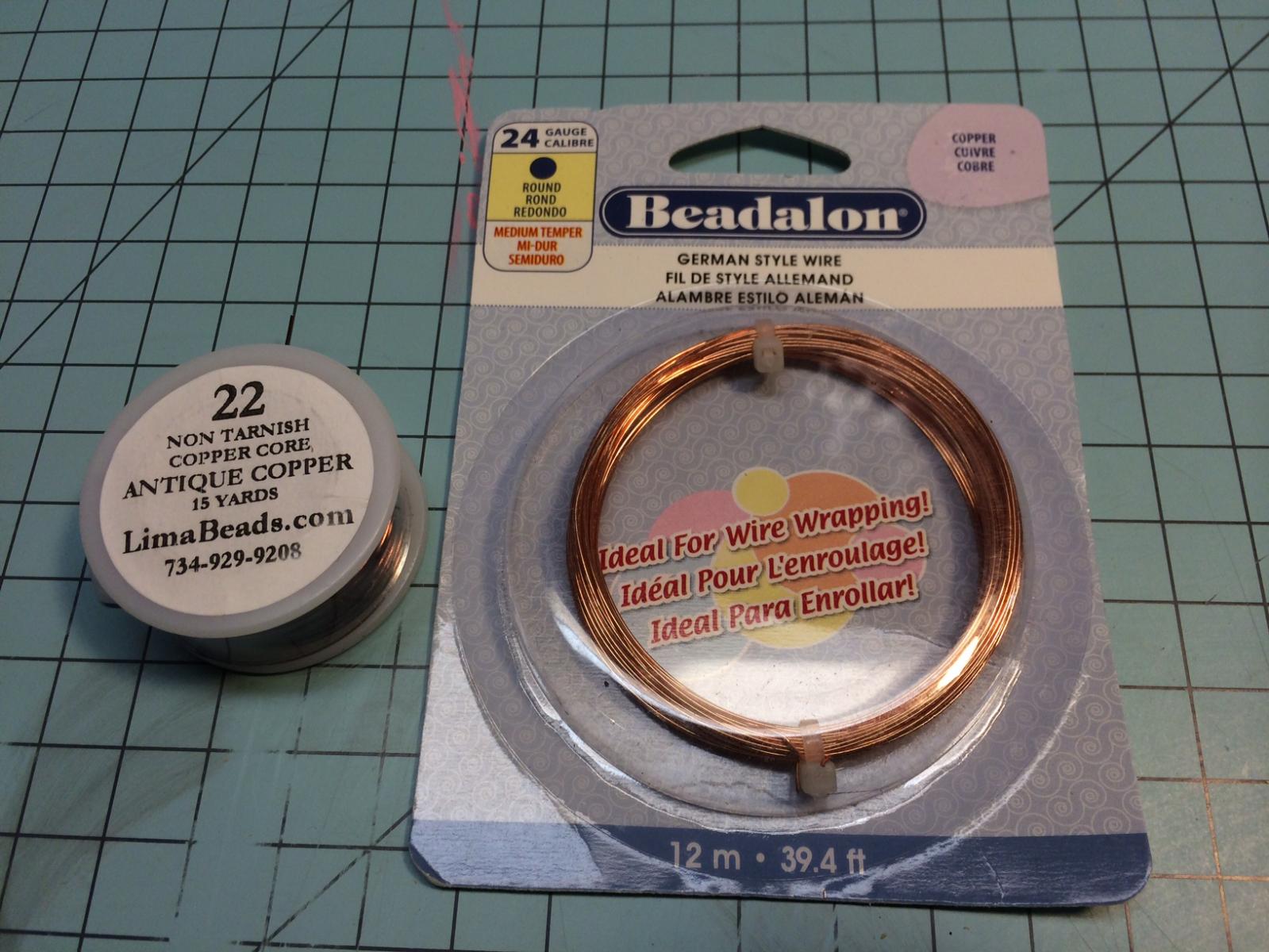
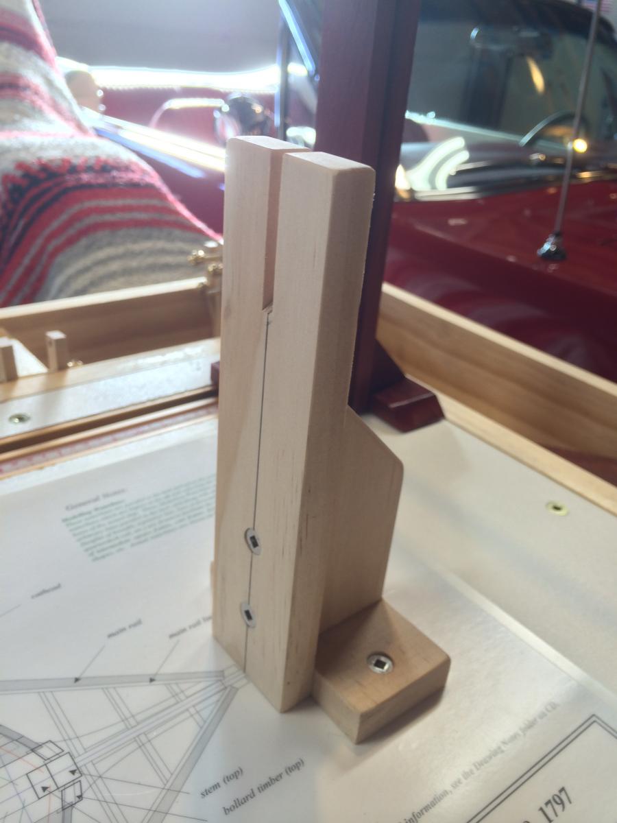
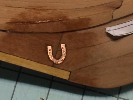
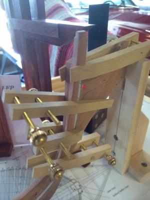
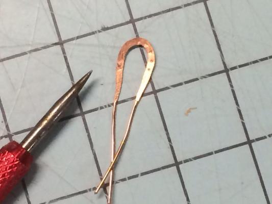
Bollard Timber Saga continued... Afer ten attempts, I managed to get the correct angle on the bollard timbers. In the end, this was very rewarding. What I lack in talent, I make up for in perserverance Here are the port and starboard timbers. They were size and shape matched prior to installation. One of the big take aways for me from Ed's book, Naiad, was the pre-fitting, clamping and pinning of pieces prior to glue in. I see this as a dress rehearsal for how it should go. As a result of these few extra minutes, I now fine tune pieces and am placing them with minimal glue slop. Note the pins. I have already aligned everthing, adjusted my clamps and know it all correlates to the plans. once satisfied, it was just a matter of a little glue and then to slide he piece in place and clamped. Note the alternating clamps. This is so I evenly distribute the pressure and didnt cant these critical frames... Prior to installing more timbers, I went ahead and installed the dovetail plate in the stern keel (not shown) as well as the horseshoe plates at the stem. I thought this would be easier now, given I could lay the keel flat for inlay. I used 22ga copper wire that I first bent around a small tube to get the proper radius. I then hammered it flat, indented for the drilling and the rest was history. I used a small micro chisel to carve the location of the inlay. The bolts are 24ga copper wire that I cut a little proud and then peaned in with a hammer, thus securing the plate. I did add some CA glue for ensurance. Here is the short under frame installed. Pains were taken to ensure they were equal athwart ships. I used the base drawing and a square to ensure thier location. Dont want to be lopsided here. The final act of the weekend was to slice my index finger open with a #11 blade. I spent the rest of the day in the ER, getting stitches. I had gotten sloppy with my knife safety... Ugh...


-
Hi Ed, as with your Naiad, there are so many great lessons packed into this log that can be transferred into any build. I really appreciate the time you are taking to explain them. Best, Gary
- 191 replies
-
- 6
-

-
- young america
- clipper
- (and 1 more)
-
HMS Naiad 1797 by albert - FINISHED - 1/48
GDM67 replied to albert's topic in - Build logs for subjects built 1751 - 1800
Hi Albert, Your log is an absolute inspiration in for my own Naiad build. I have been referencing it quite a bit. The fit and finish as well as overall composition is outstanding. G -
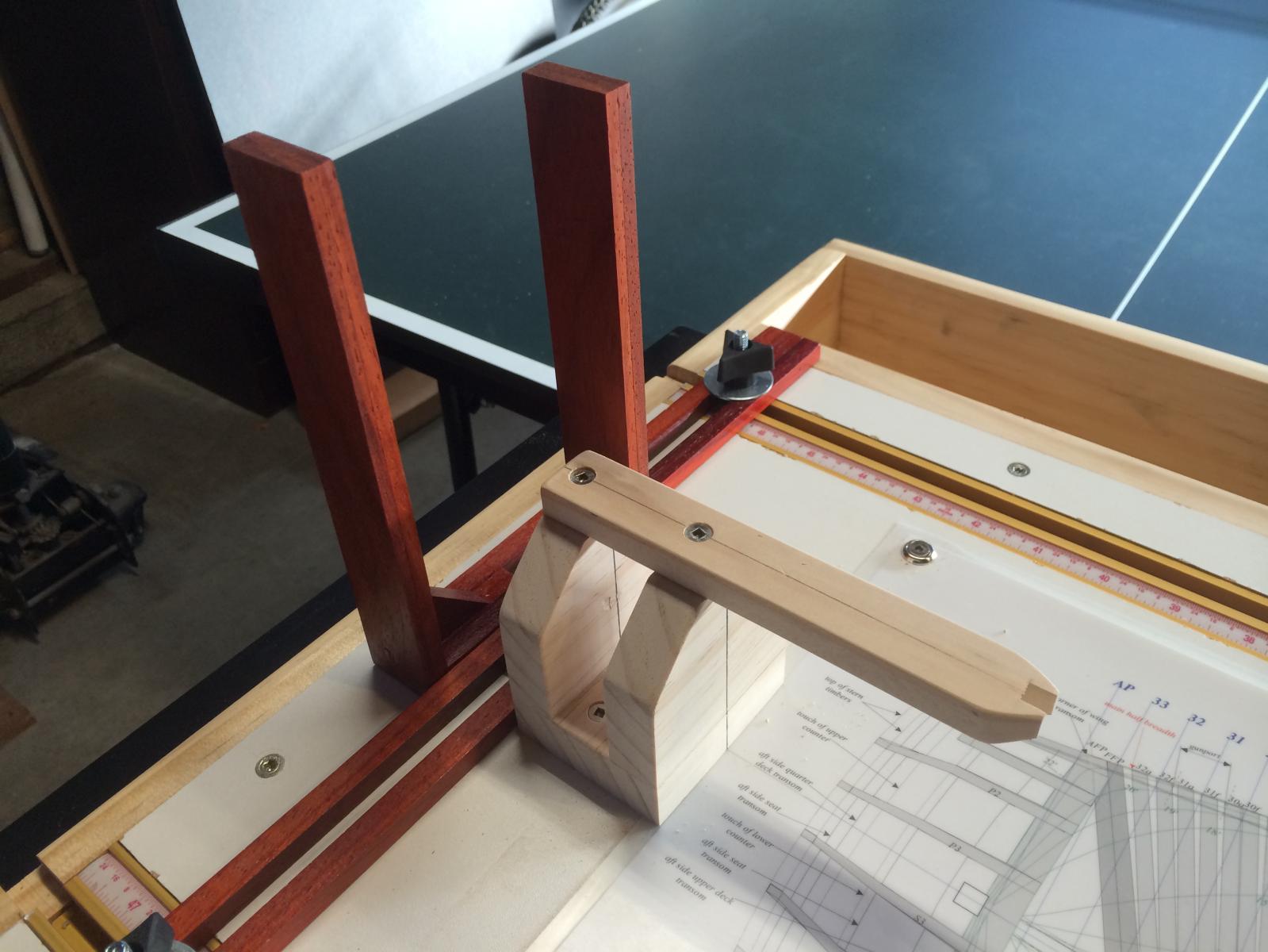
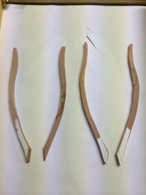
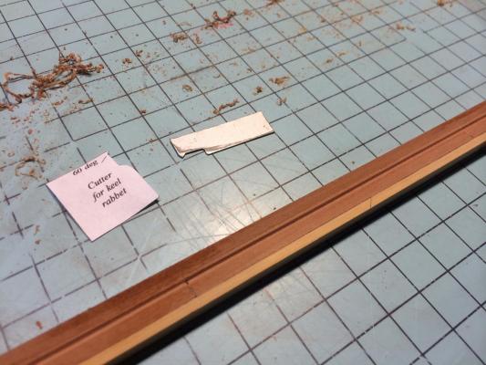
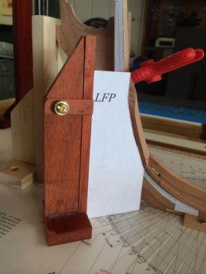
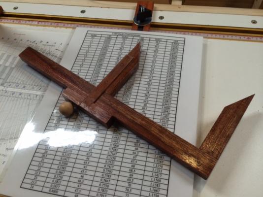
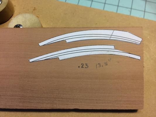
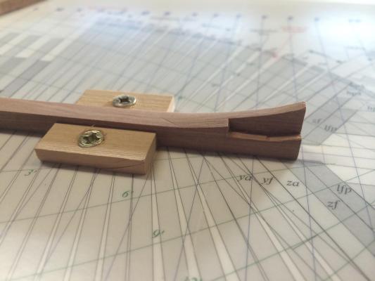
Work continues on the keel detail. I have to admit that I was a bit concerned about scrapping the rabbet into the keel. I have always done this with a #11 blade and some files. But no more! It took about ten minutes to fashion a scraper using the pattern from the book and in another 20 minutes, I had perfect a perfect keel rabbet on both sides! I just started with very light scrapes, never getting gready and it all worked out fine. The scraper in the photo was made by using an old saw blade for an exacto knife. I ordered some copper wire for $7. The info is on the photo. I then installed the wire, pulling it first to anneal it and dipped in CA. I think the 22ga wire used a #71 drill bit. I drilled the holes using my new Microlux press that Santa brought. Yes, the bolts are too close together, not sure where my head was at the time, so if you are copying my work, please refer to the book for proper spacing. I will live with this error... Now for the fun stuff! Below are the Bollard timbers as well as the hawse pieces. I have made four sets of Bollard timbers as a result of not being able to get the proper angle at the foot. I have scratched my head about this for many hours. And have come up with a plan that I will execute this weekend. Here are the short timbers that attach to the Bollards. It is absolutely essential to get the right angle in all directions here. Small variations will translate into bigger headaches down the road. In efforts to get the angles right, I have done the following: Ensure the bollard timber foot angle is 34.5 degrees. Dont just rely on your grinder for this angle. Prefit the bollard along with the short under timber and work with the shipway drawing to see that everything lines up. Ensure the bollard foot is perpendicular to the keel - this should be intuitive, but was not for me! This will allow the first short timber (as noted above) to lay up against it and remain perpendicular to the keel. Otherwise, this timber will lay over slightly and every piece thereafter will do the same. I made a template jig that clamps the template square so that I can prefit all these pieces. I really like this jig. I am going to put removable arms on it that will clamp to the t-track so that it wont move when I fit pieces. This build makes great use of templates, so the investment in time is well worth it, and its also fun to make new tools. I will take a few more pictures of the jig and post more detail in my next post. Once the angle is correct, I will glue the bollard and then finish scraping the stem rabbet. There is some further detail work to be done on the keel before I start attaching the frames. The foot of the template should be lined up with that on the shipway. It is not in this photo... Refelction: As I build this ship, I am really changing the way I look at modeling. While not a fast modeler in the past, I was always looking forward to the next build or piece. Now that I am five ships in, I have decided to strive for higher quality and fewer ships. I keep all my work (my kids will get them some day...). This build incorporates modeling skill, perserverance, education, math, puzzle building, ship building, ship design and obsession all into one. I hope to share the bollard timber results after the weekend. Best, Gary


-
Palladio, I greatly appreciate the how-to on the lamp as well as the different views in the photos. I agree with Dirk, your building style really conveys a life-like warmth. I look forward to more photos and how-tos as your time allows. Best, Gary
-
Exceptional work here. I would love to see a play by play how-to of some of these items - lamp, stove, capstan, figure head, you name it. G
-
Hi Toni, Beautifully done and inspirational. Specifically, your sharing of both pitfalls and successes will be of significant value to me as I am constructing the Naiad in the same fashion. All the best! Gary
-
Hi Ken, She looks beautiful. I finished my Mamali kitbashed Rattler last summer. Yours has really great lines. I will follow along with interest. Gary
-
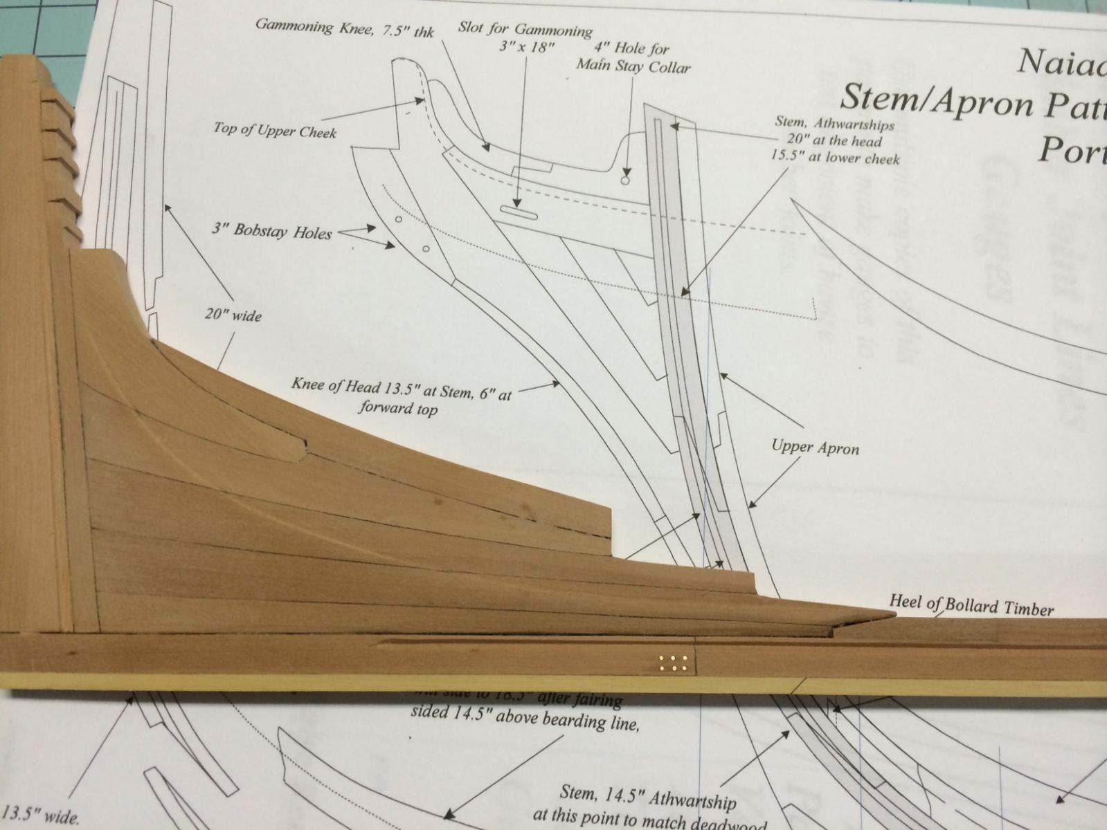
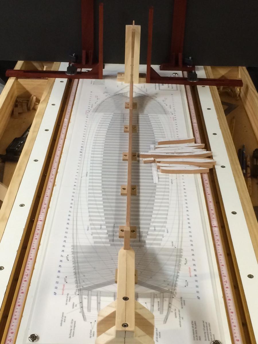
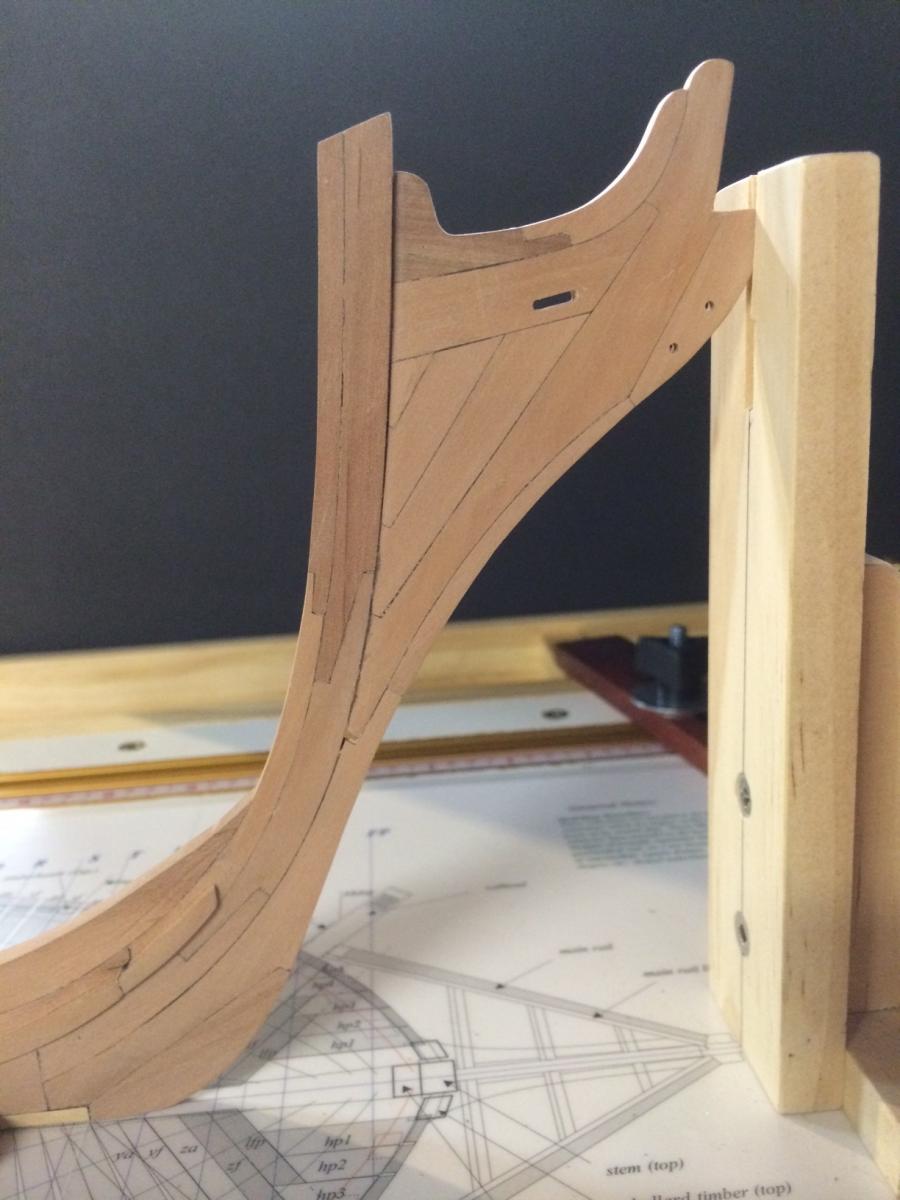
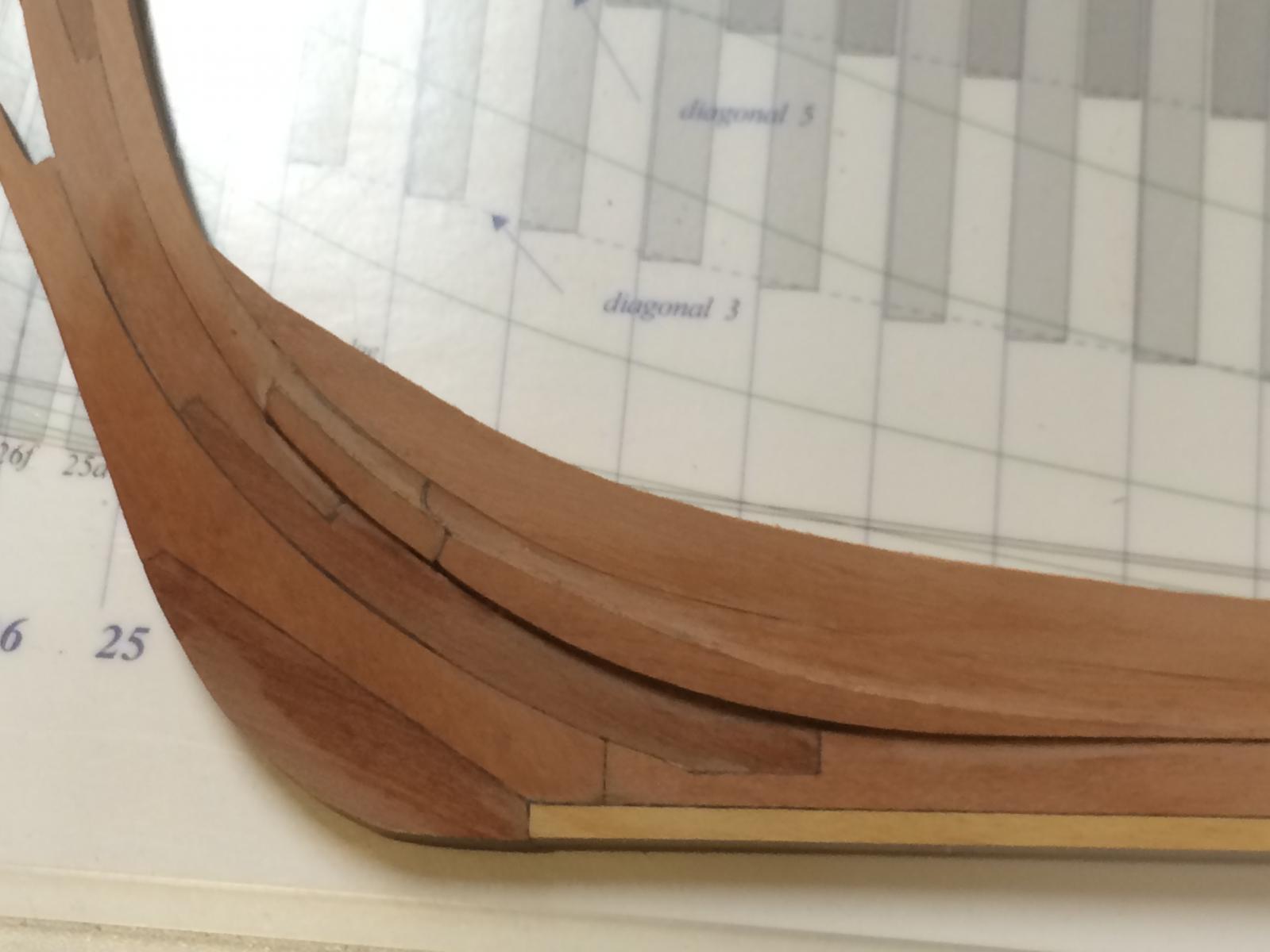
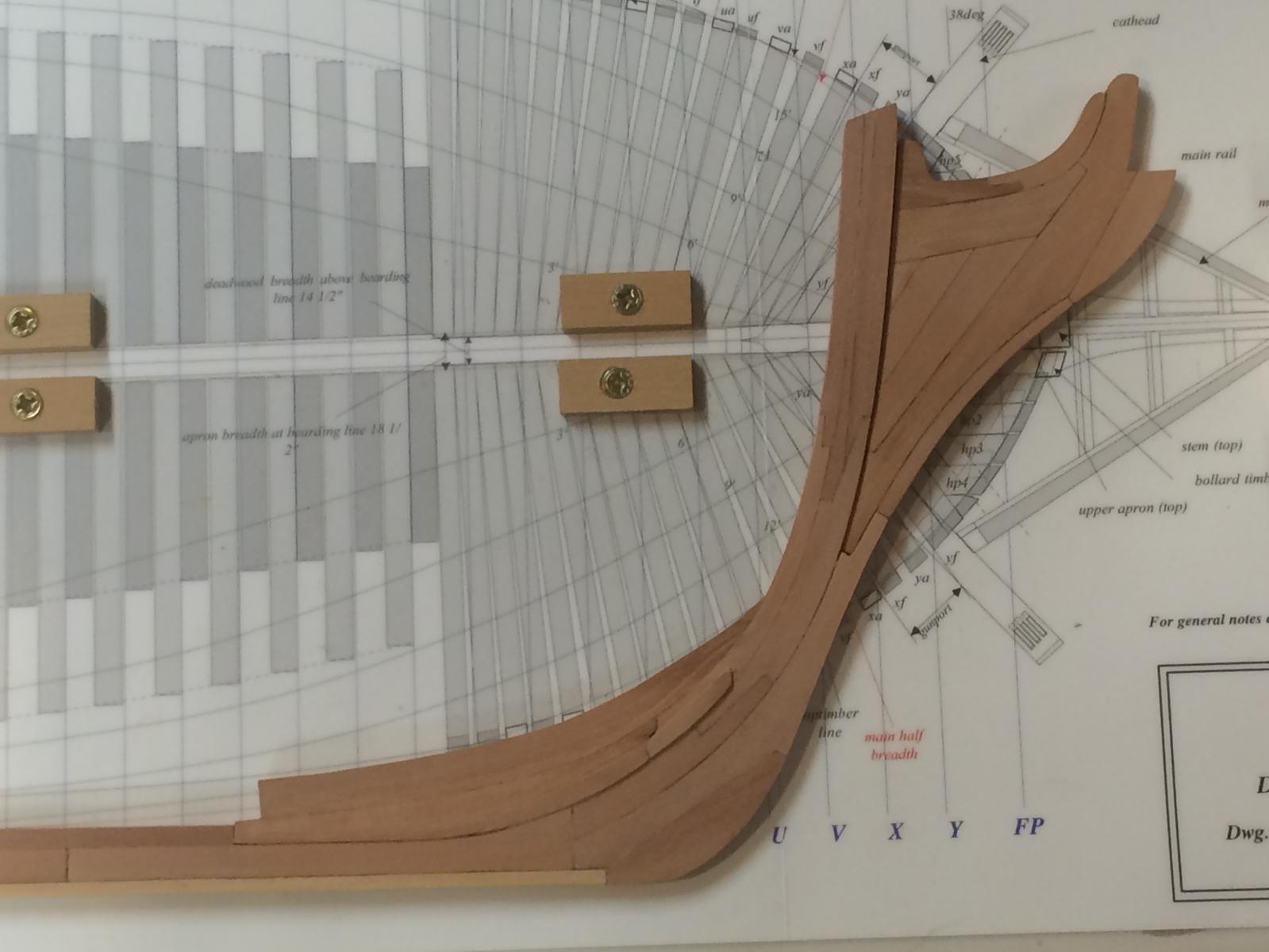
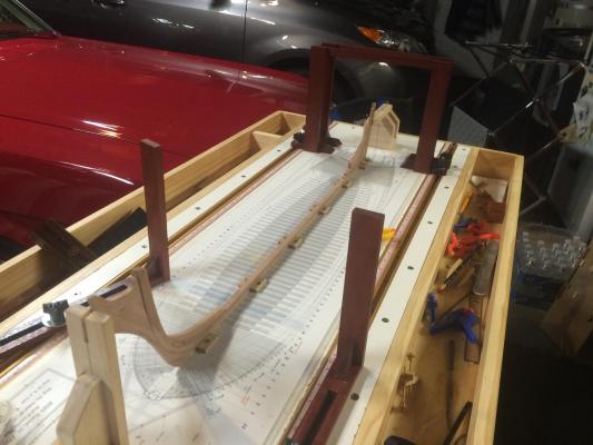
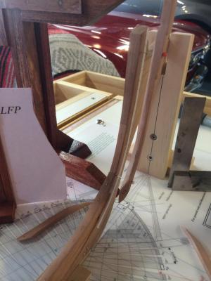
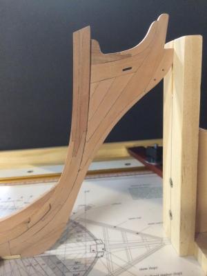
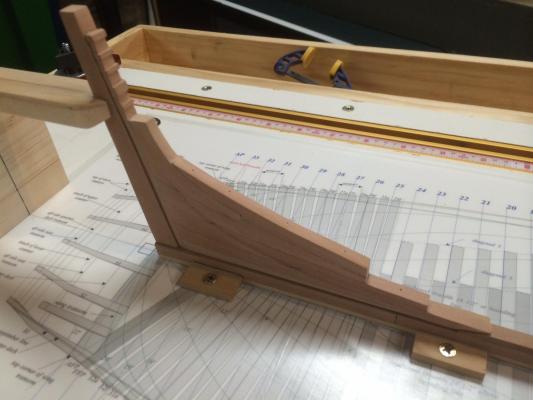
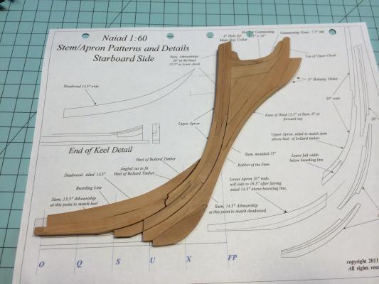
Stem - Keel - Stern: Progress is slow and steady on the Naiad. The entire backbone of the ship is all glued up and sits on the shipway, ready for the finishing touches before framing begins. The Stem and Head of Knee all ready. I cut the gammoning slot using a small drill bit to puch out successive holes and then cleaned it up with a file. If I were to do this again, I would cut the gammoning slot before tapering the piece! I had to angle the part so the slot would be perpendicular to the piece when fayed to the stem. Also, if you are temped to not make the jig for tapering the knee of the head as outlined in the book (as I was), then you run the risk of having a bent nose to your ship (trust me on this and learn from my badly chosen shortcut). I was able to correct the "bent nose", but the part could have been perfect, not just very good... I still need to cut the rabbet as well as install the copper nails. I ordered some antique copper wire in 22 and 24ga. for this purpose and will show it once it arrives. I am very happy with the stern deadwood structure. A simple structure that was tricky to make due to all the angles. In the end, just study how this should look on the real ship and then execute. Its all very logical once studied. This is how she sits on the slipway. I am very pleased with the results. There is a subtle taper fore and aft on the keel structure that I have never inclued in my previous models. This is a really nice touch and is a result of precise plans and research by EdT. My hat is off to him again for creating such a wonderful monograph. I will be switching back to my US Brig Eagle to start the masting, and will start a log on that here next week. All the best, Gary

-
I too, look forwar to you progress. I love the helpful hints and the lists of lessons learned. Gary
-
Thanks for the kudos, guys! I really appreciate them. Alan - the locking cam idea is EdT's from the Naiad book. There are so many of these golden nuggets in this book. I will keep the details coming as I go along, with an emphasis on highlight those not already covered by Ed and Albert. BTW, I reallly like your log on building a modeling table. I will use some of those ideas this spring as I revamp my shop for more efficiency. All the best! Gary
-
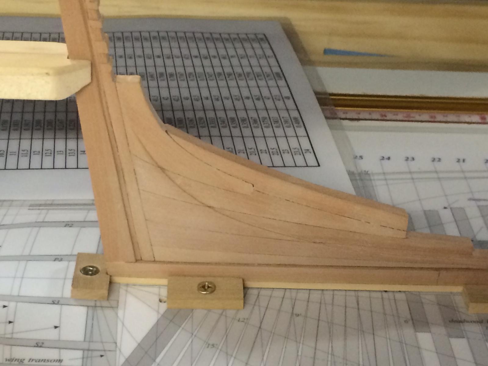
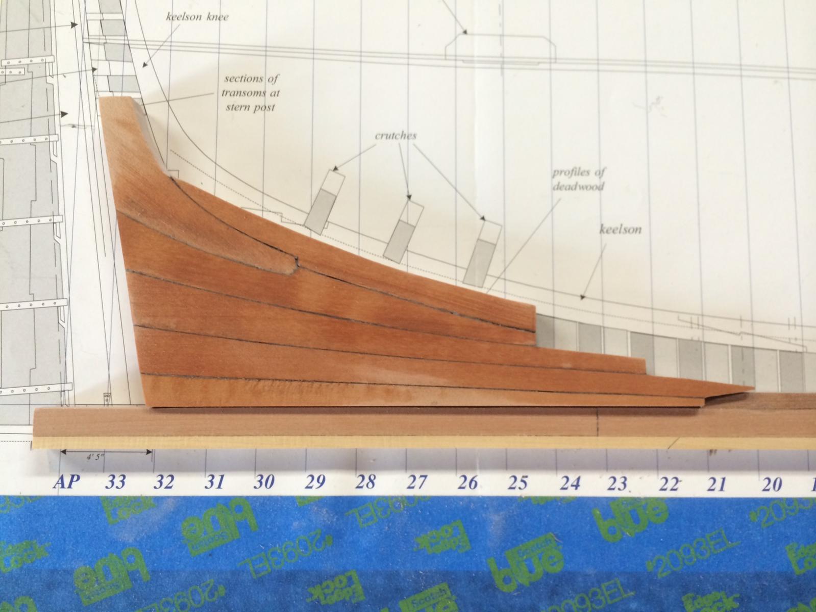
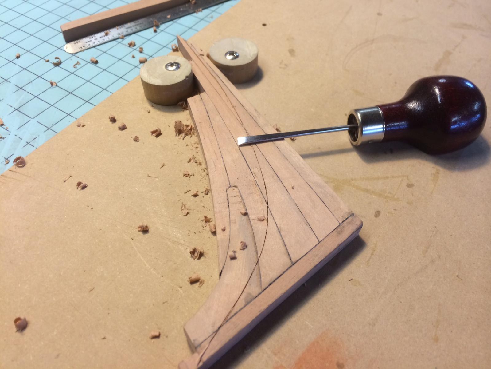
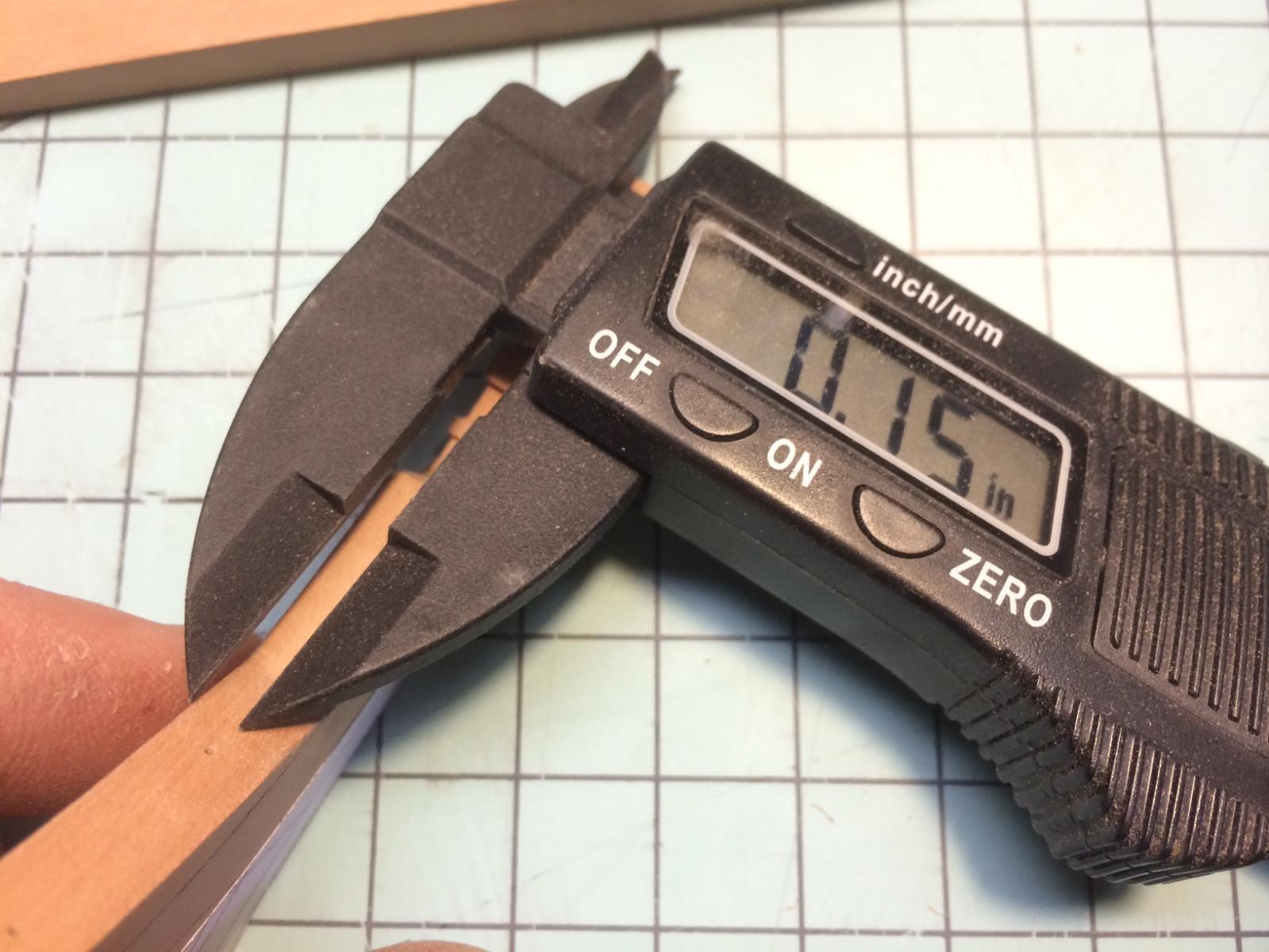
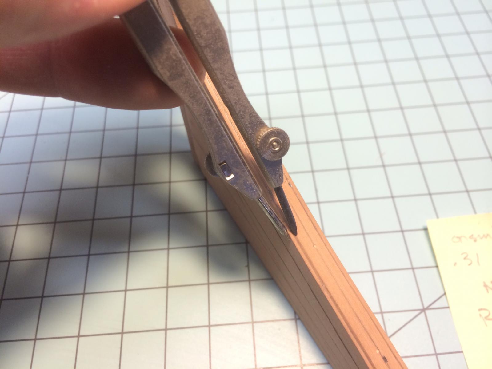
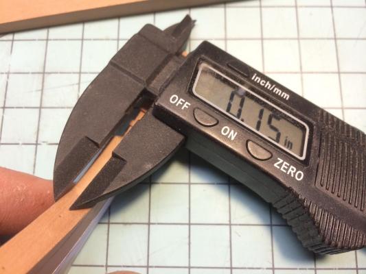
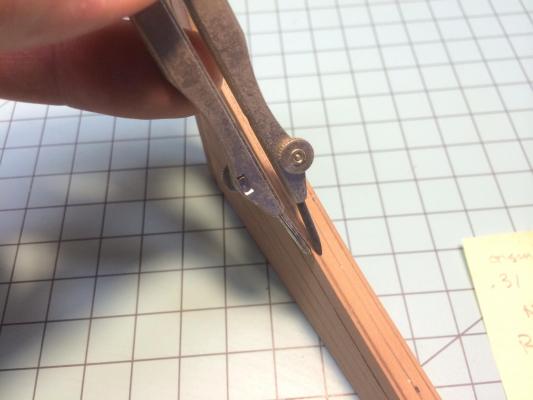
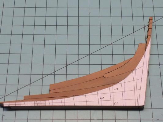
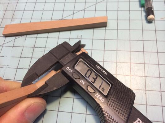
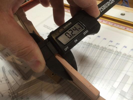
Stern Deadwood - I spent the weekend working on the Stern Deadwood. This was a bit of a challenge because I was having trouble visualizing how it should look when complete. I actually made the piece twice! There are many angles that I needed to take into account - specifically, how the planking would flow into the rabbets as well as the keel. The Naiad is my fifth ship and the first ship that I used calipers on. In the past, I was content with just using a ruler to identify 1/4 stock, but with my calipers, I get it down to the hundredths. I find it very enjoyable to be this precise and it only takes a little extra effort in diligence to up your game. It has for me. Stern Deadwood glued up. I wetted it down for the photo to show the joint detail. Most of which will not show in the final product, but hey, I love god and will build some detail for him! Still to be added are the inner post as well as the stern post. I will then cut the keel to size. Important to remember is to keep the correct angle of the keel when trimming. Also, there is a cumulative affect when using the pattern sheets. The glue joints, will increase the overall size of the piece, so some subtle trimming is necessary when finished. Double and triple check the angle of the keel and stern post. This is another critical angle of the ship. Pattern sheet installed on both sides of stern deadwood in preparation for cutting in of the bearding line. I scored this line with a #11 blade, making multiple cuts, each deeper into the wood. This allows for a break line when chiseling out the bearding. A couple of examples of using the calipers to measure center as well as the depth of cut for the bearding. I used a compass to mark the material needed for removal. As I type this, my fingers ache. I spent the better part of four hours cleaning this bearding line up, using a variety of tools, mostly a small chisel, razor blade for scraping and a small file. When it was all done, the notching of the stern deadwood was exactly the 14 1/2" as required. Well worth the time and effort! A couple of shots of the near finished stern deadwood. I still need to cut the rabbet into the stem post as well as glue the assembly onto the keel. It is just set in here. A few interesting details: Make sure the inner post is notched for the transoms with an angle parallel to the keel and not the piece itself. Even though this was written in the book, I did it wrong on my first attempt. Also, as mentioned, the aft rabbet will extend past the inner post and notch into the stern post. It will be flat below the transom and a "v" angle at the area of the transoms. More to come next week. Thanks, Gary


-
Again, thank you for all the great comments and support. I appreciate all the "follows" and look forward to the popcorn and beer! Greg- good eye on the "S-curve" of my lower apron, I hadnt noticed this. Although the glue-up has already happened, it wont show in the final product. I appreciate the comment and will be sure to incorporate it into my next ship. As for my log - Since EdT and Albert have done such an outstanding job narrating thier logs, not to mention Ed's books, my plan here is to focus more on techniques and sequences not already illustrated. No sense talking about measurements, since that stuff is already well documented. Below is the lower apron/stem/keel all glued up and ready for final sanding, which will not take place until further down the road. The knee of the head has not been glued in yet. I still need to taper it as well as cut the gammoning slot. I am waiting for my new micromark mini drill press that Santa is putting under the tree, courtesy of my wonderful Admiral. I opted for boxwood on my false keel and did not ebonize it. I just liked the look. I used ebony on my Rattlesnake and was looking for something a little different. I also prefer natural woods as opposed to paint. While I want to be historically accurate (and this build allows that), I am not a strict purist in the sense and will carefully defer to artistic license at times. Over the weekend, I plan to install rising wood, the bollard timbers, taper and install the beak, cut the rabbet, and construct the stern deadwood. Yes, I am goal oriented... Happy Holidays! G

-
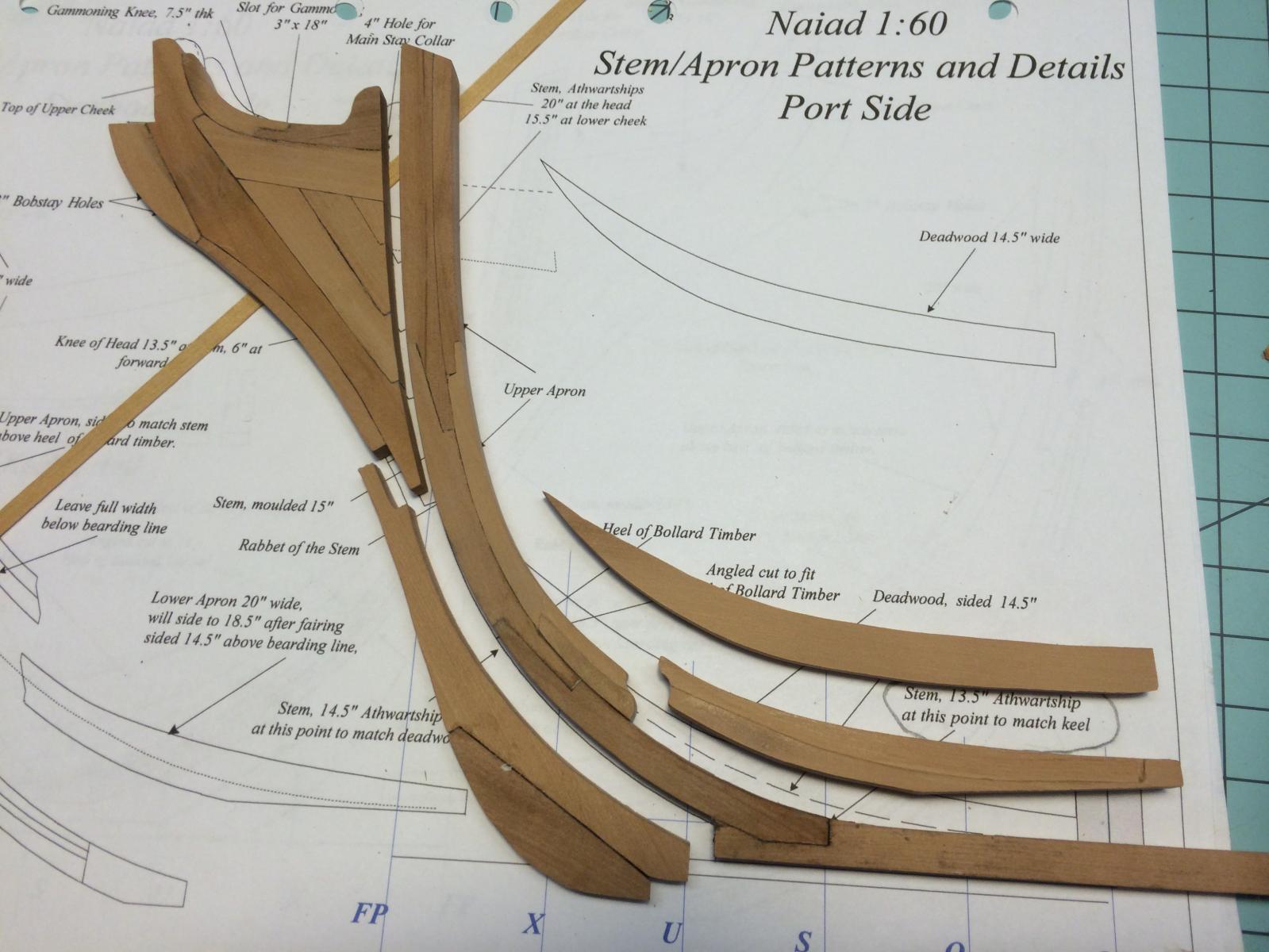
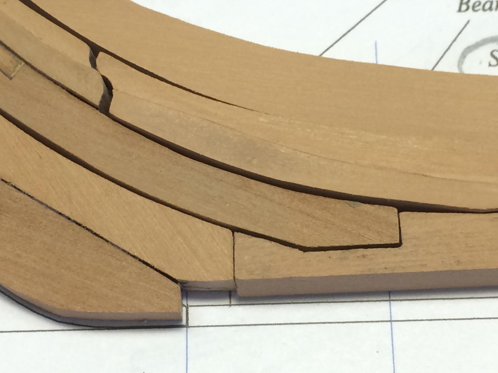
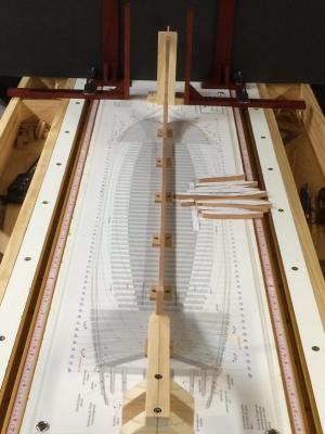
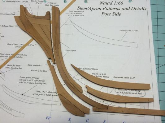
Hi All, Thank you for the kind words and warm welcome. Very motivating. You may note that in my last post of the gantry, I double laminated the crossmember, this was to mitigate any twisting, which did happen with my first attempt. I will be building the Naiad from Swiss Pear, West Indian Boxwood, and Holly, all purchased as billets from Dave at D'Lumberyard. I really enjoy milling my own stock and allow for a few hundredths of extra thickness for fine tuning and sanding. The false keel will be ebonized swiss pear. I really dislike working with ebony for a variety of reasons. Below is a photo of my calipers as suggested in Ed's book. I made these of Babinga. Next time, I would do without the Shellac and would center the screw and sleeve clamp. I have been working on the model for the past few weeks and came across a significant pitfalls that I will share: Scale of pattern sheets - I printed out the pattern sheets from the disk, but neglected to scale the prints to "full size". This error was not detected until I built the full stem, and beak! Oh well, back to the drawing board I went. While it was only off by a smidge on each part, the cumulative affect was significant. I then read Ed's log and sure enough, he addresses the issue there. Here are the patterns for the stem, cut out and ready for fitting. You will note that in this second photo above, I glued up the box joint where the stem meets the keel. In my first attempt, I got this angle wrong. I decided to do it earlier than suggested by the practicum so that I could better tie the whole thing together. This is probably one of the most critical angles/relationships in the ships structure. Below is a close up of the box joint. More to come. Thanks again for the warm welcome. Gary

-
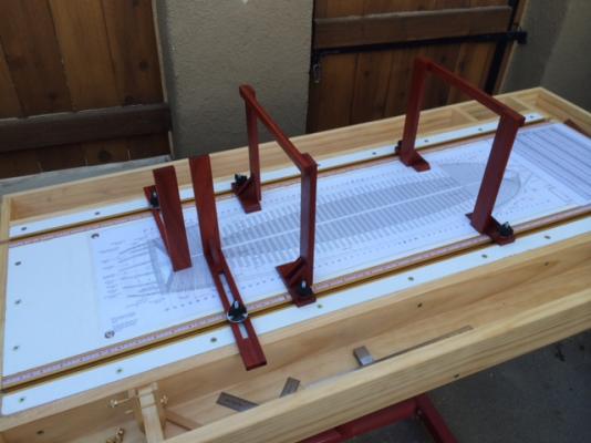
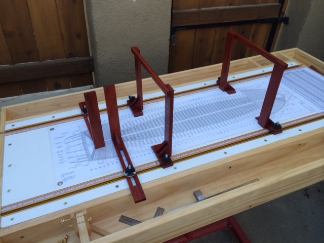
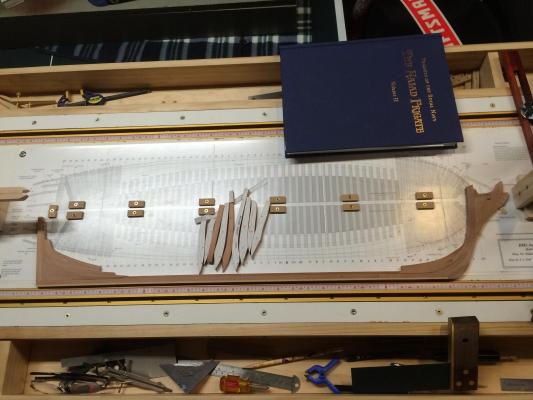
Hi All, I am new to the forum. I am very active on another forum, but decided to join here after meeting so many wonderful people at the NRG Conference in Mystic this past fall. While at the confernece, I stumbled upon Ed Tosti's masterpiece, The Naiad Frigate,Vol 1 & 2 from SeaWatch Books. I bought them and devoured them. There is so much great information in these books for all levels of modelers. In addition to the books, Ed's log and that of Albert will come in handy as I progress. As for me, I consider myself a new intermediate modeler and welcome all constructive comments. I just finished a kitbashed POB Rattlesnake and am starting the rigging to a POF US Brig Eagle scratch build. I was not planning to start the Naiad so soon, but here it is... Since I do all of my modeling while standing in the garage, I built the building board at about 42" height. I plan to use it for more projects after this, so the construction is very solid, using kiln dried pine 1x4 and melamine. I also put in some trays so my tools wont end up on top (thats the theory...) It has the T-Tracks as specified in the book. I opted for a laminated copy of the builidng plan, since my first attempt at a spray adhesive for gluing the plans down didnt look so good. The laminated plan was less expensive than the glue. And, I like the results much more. You will note the gantry and uprights are made from Padauk. I had some laying around so decided to use it. They are also glued, screwed, and pinned. I am planning for a long life and a life time of use... The stern and stem holders are made from simple kiln dried pine and are also glued and screwed. I scored the center line to ensure that everything lines up (or so I hope...) I made multiple sets of clamps from Boxwood and 6-32 brass screws and thumb bolts. These were fun to make and really come in handy. I like them better than the small colored clips since you can adjust the pressure. Also shown is my version of the framing jib. I made a double jig as shown. In my next installment, I will share my work on the stem, knee of the head and keel. All are coming along nicely. Thank you, Gary