HOLIDAY DONATION DRIVE - SUPPORT MSW - DO YOUR PART TO KEEP THIS GREAT FORUM GOING! (89 donations so far out of 49,000 members - C'mon guys!)
×


GDM67
-
Posts
103 -
Joined
-
Last visited
Content Type
Profiles
Forums
Gallery
Events
Everything posted by GDM67
-
Hi Larnan, Thanks for the kudos and the advice. I guess I will take your advice and go ahead and clamp the ship down to the board with screws... Is your build on line? I couldnt find it. I would love to follow it. Thanks, Gary
-
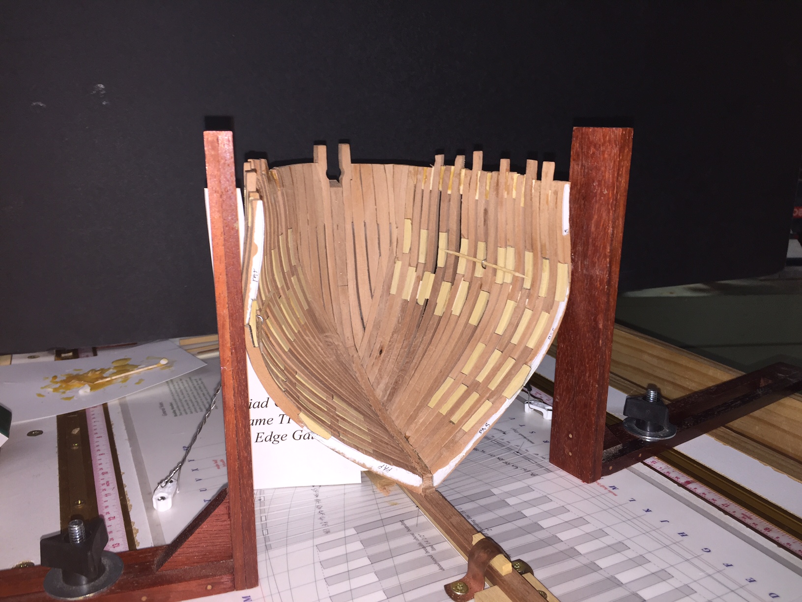
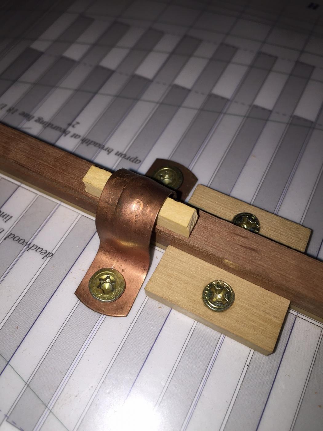
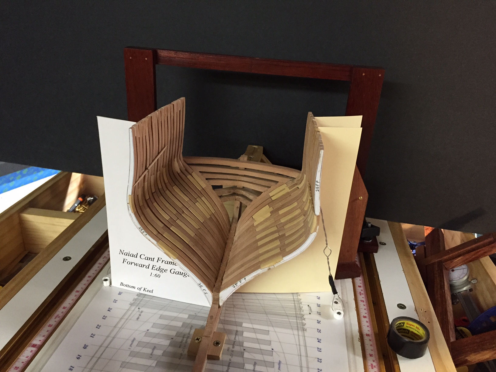
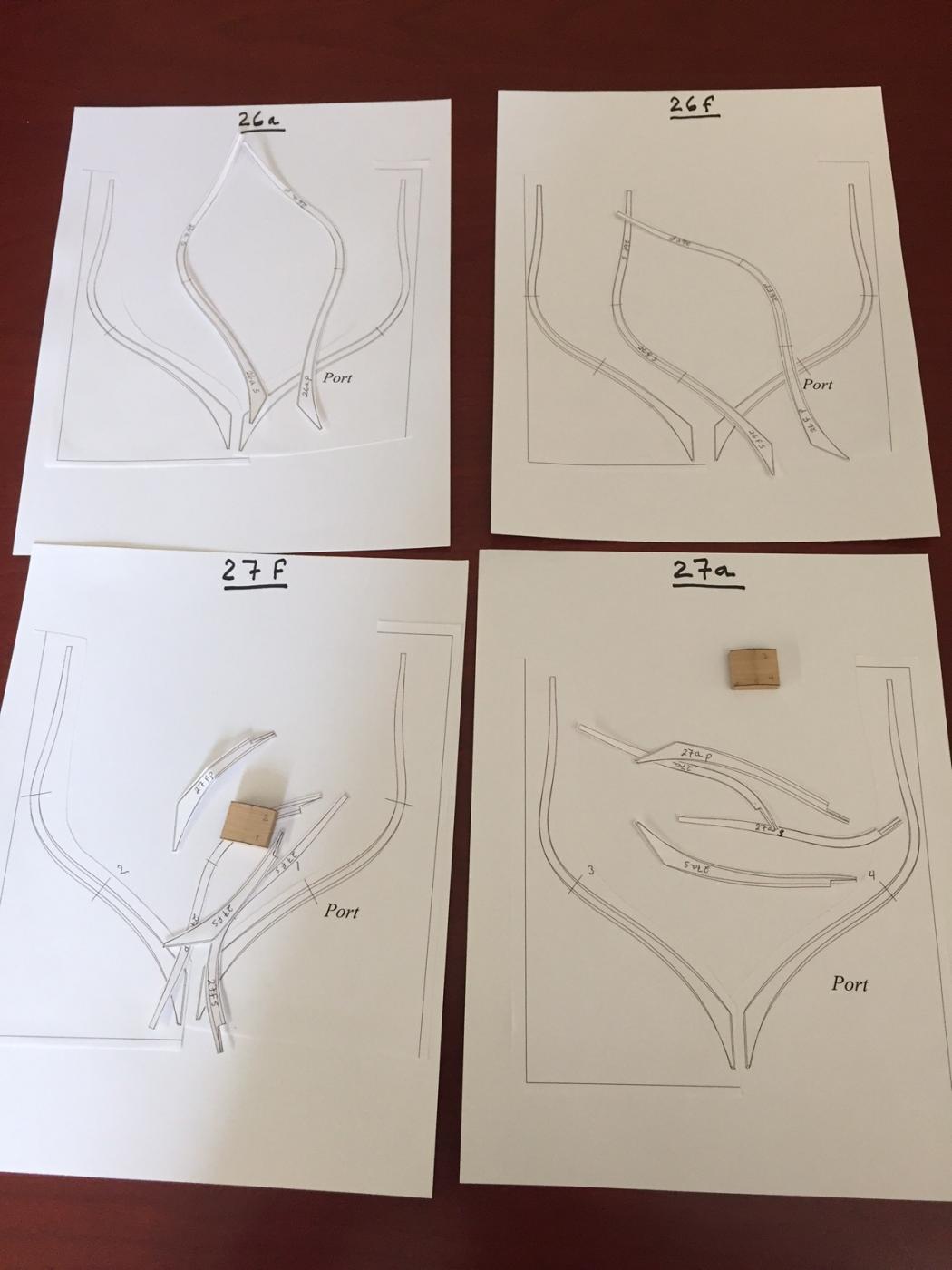
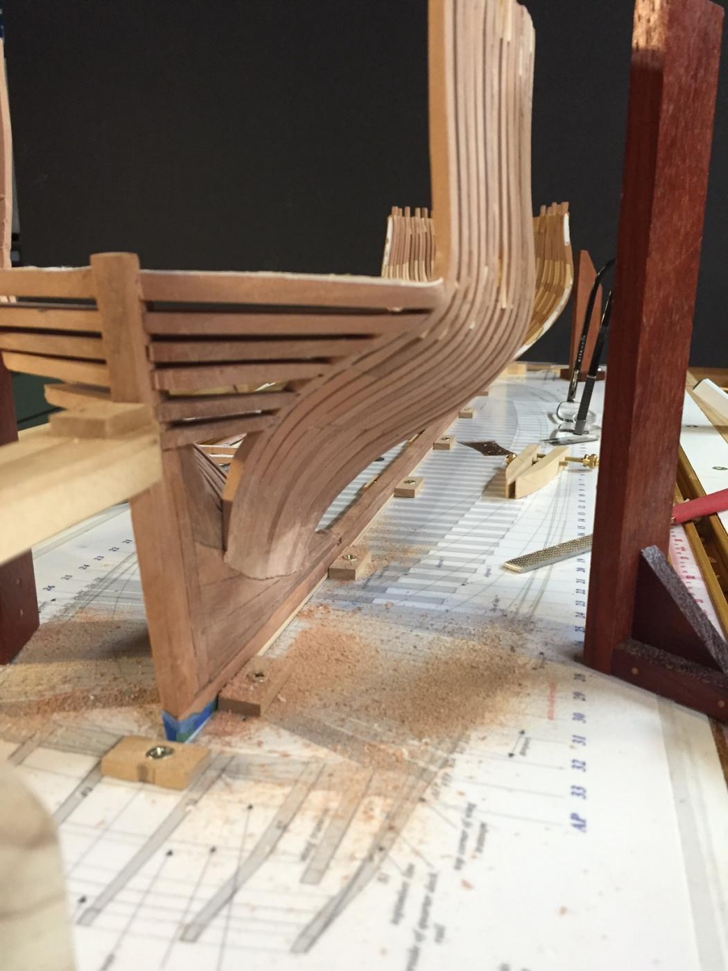
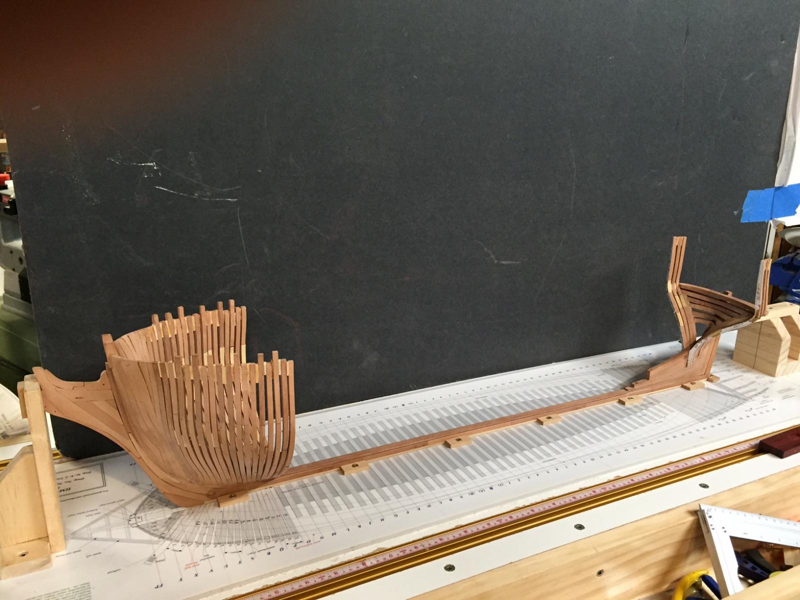
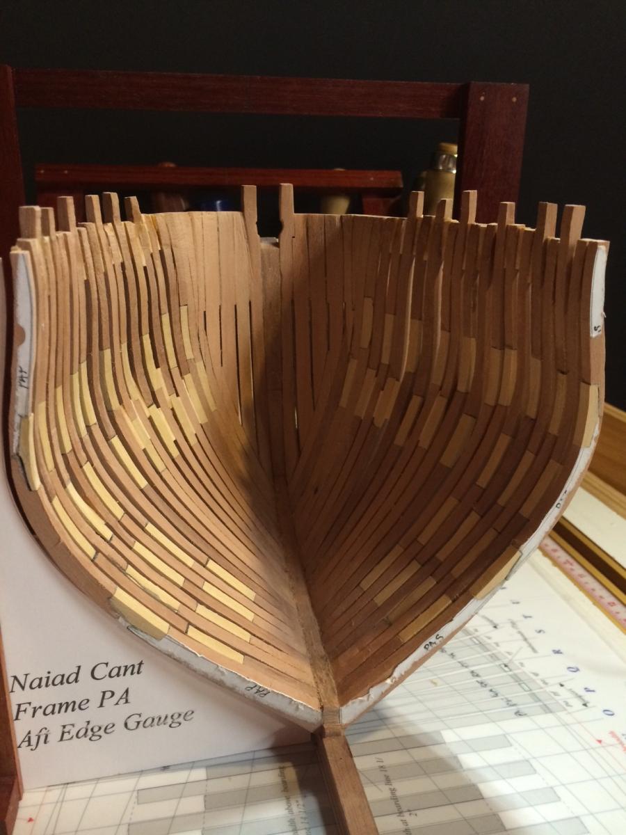
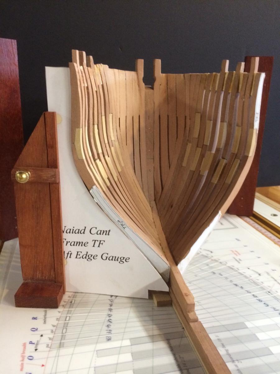
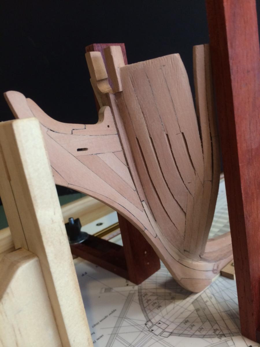
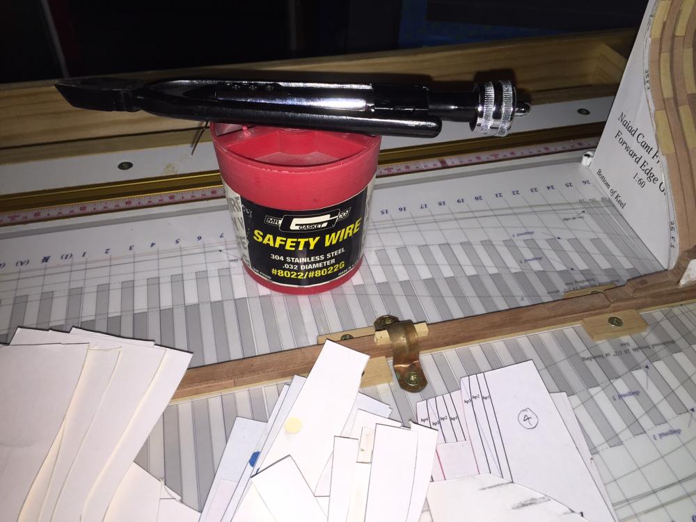
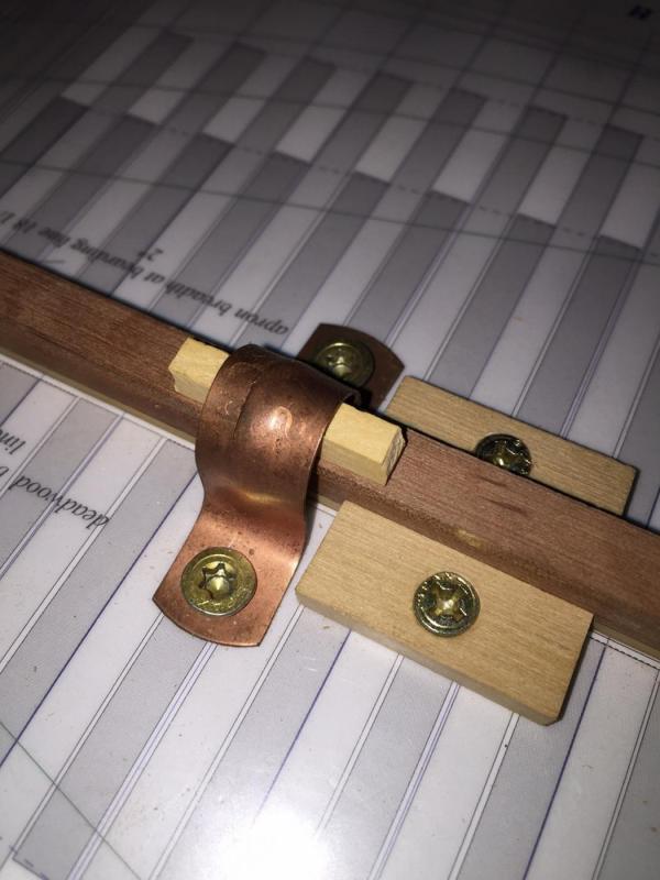
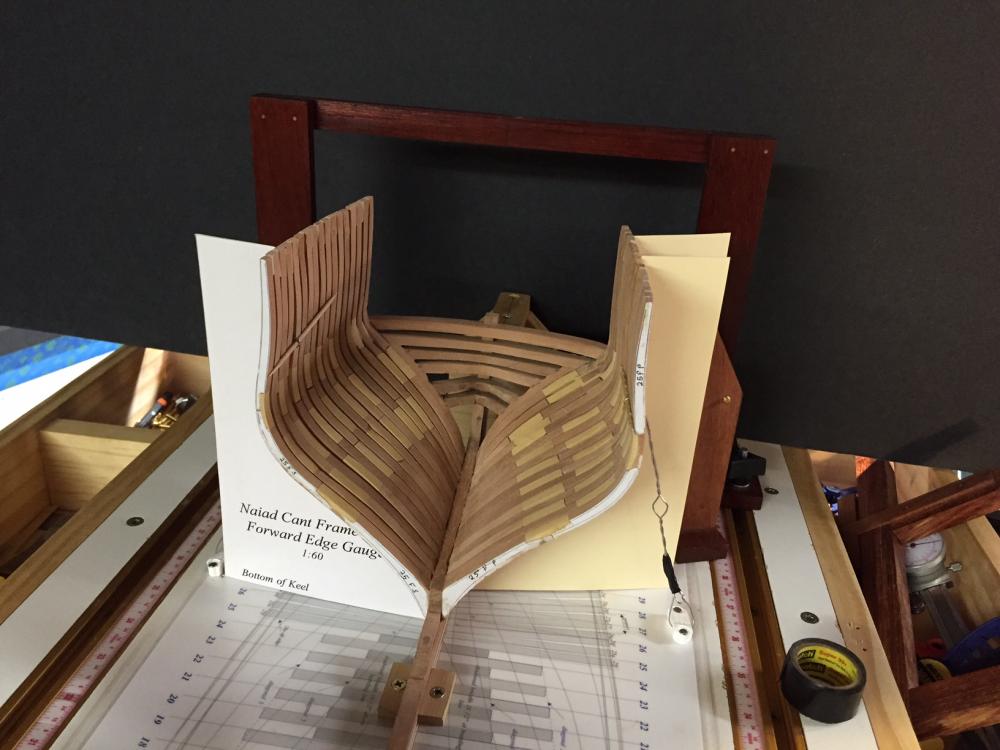
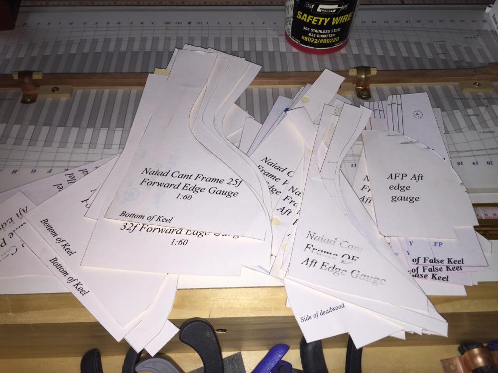
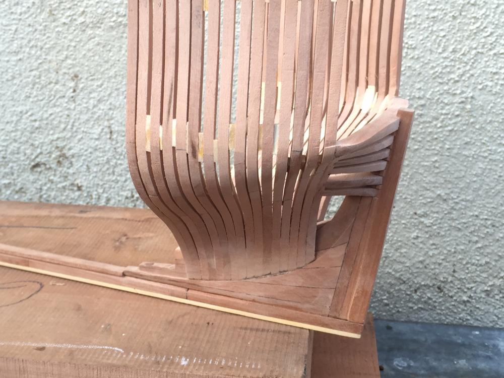
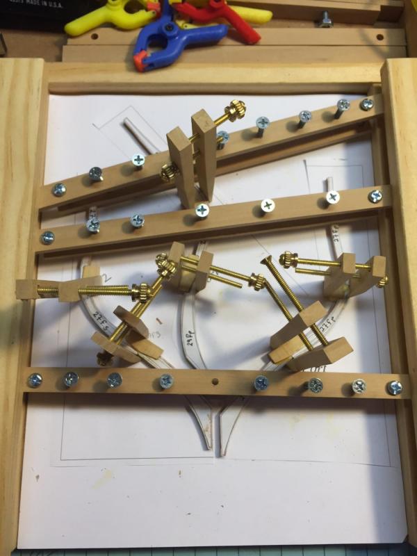
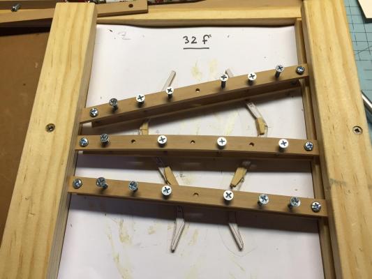
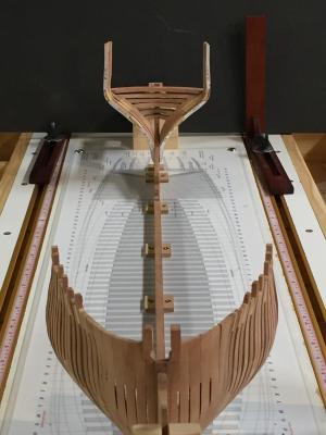
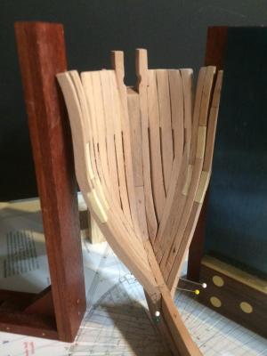
Hi All, Thanks for the likes and comments. Allan, I am sure there are many ways to skin this cat. For me, I think ideally, you should leave a little meat on the bone for final fairing, but again, I think with this kind of build, final fairing is mostly fine tuning and polishing. This build requires reliance on the templates. Another important thing to do is secure your build to the build board. Being off by an 1/8th of an inch can lead to trouble. I FINALLY secured my ship to the build board last night. About two months later than I should have - this is an important thing to do. Learn from my mistake... Here are those many templates that I have been speaking of. I pasted them to file folder stock and made a special jig to hold them up when positioning frames. I used stainless steel safety wire to stabalize the structure. I had some from a previous muscle car project. Since I am planning to cradle the ship, I elected not to put holes in the keel for screws. I used 1/2 inch pipe clamps with a piece of wood below to pin the ship down. I will move these as I do along and will add more guide wires as well. The ship will likely be secured to the build board for the next six to eight months. Note the use of the templates to ensure that I am on the right track with fairing. In this photo, you can see that I need to remove a little more wood from the belt line so the flair of the top timber will match the template. My skill level has defintley improved as I went along. In the early stages, I left far too much wood on the frames, which necessitates significant fairing. Best to get it right at the beginning, rather than going back. Here, you will note that I faired the frames better. All the templates are spot on. Now all that is needed is fine tuning and polishing. Now that the ship is secured to the build board, I plan to define the sheer line of the top timbers and will then move on to the aft square frames. I will mill the wood this weekend. Thanks for following along. Gary
-
Mike - your comment is a good one! And yes, the frames are thin - any thinner and I will be running into trouble... At 1:60 scale, they are much thinner than the traditional 1:48 that many of us are used to seeing. That being said, the practicum is so well designed and strongly based on templates, drawings and measurements that you really need to fair the frames close to the lines before you install them. I am starting to do more of that now. If you dont, you loose the value of the reference points that you pull up from the base drawing as well as the templates. I have been leaving about a 32nd of an inch for fairing, but find a little more might be of value. I also left a little more meat at the turn of the bildge. One thing that I would not do again is make the chocks out of different wood. As you know, different woods sand differently. Also,since the chocks have to be angled to account for the beveling of the frames, so as to leave enough frame meat for the joint, there is the chance of fairing the frame into a chock. This happened to me in two places - both of which were in the early stages when I didnt angle the chock and fully appreciate the subtle importance of this practice. This is explained in great detail in Ed's book and worth noting for those of you planning to do this build. So in the end, I am moving slow for maximum speed. Doing more fine tuning of the frame before installing. In past builds, you could really just install a frame and leave much of the detail work to the fairing process. With this build, it is best to spend the time to properly fit and finish each frame as you install them, leaving the fairing process for fine tuning and polishing. Thanks for the dialogue. G
-
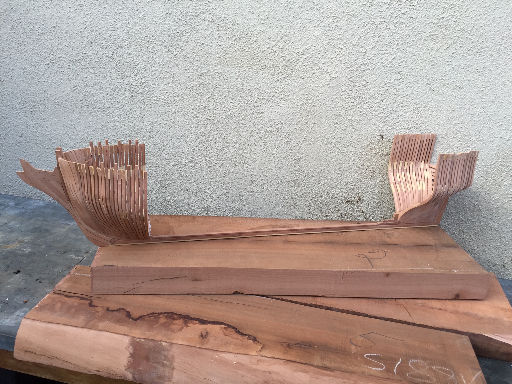
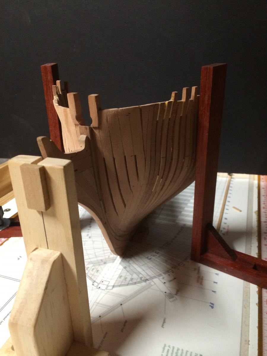
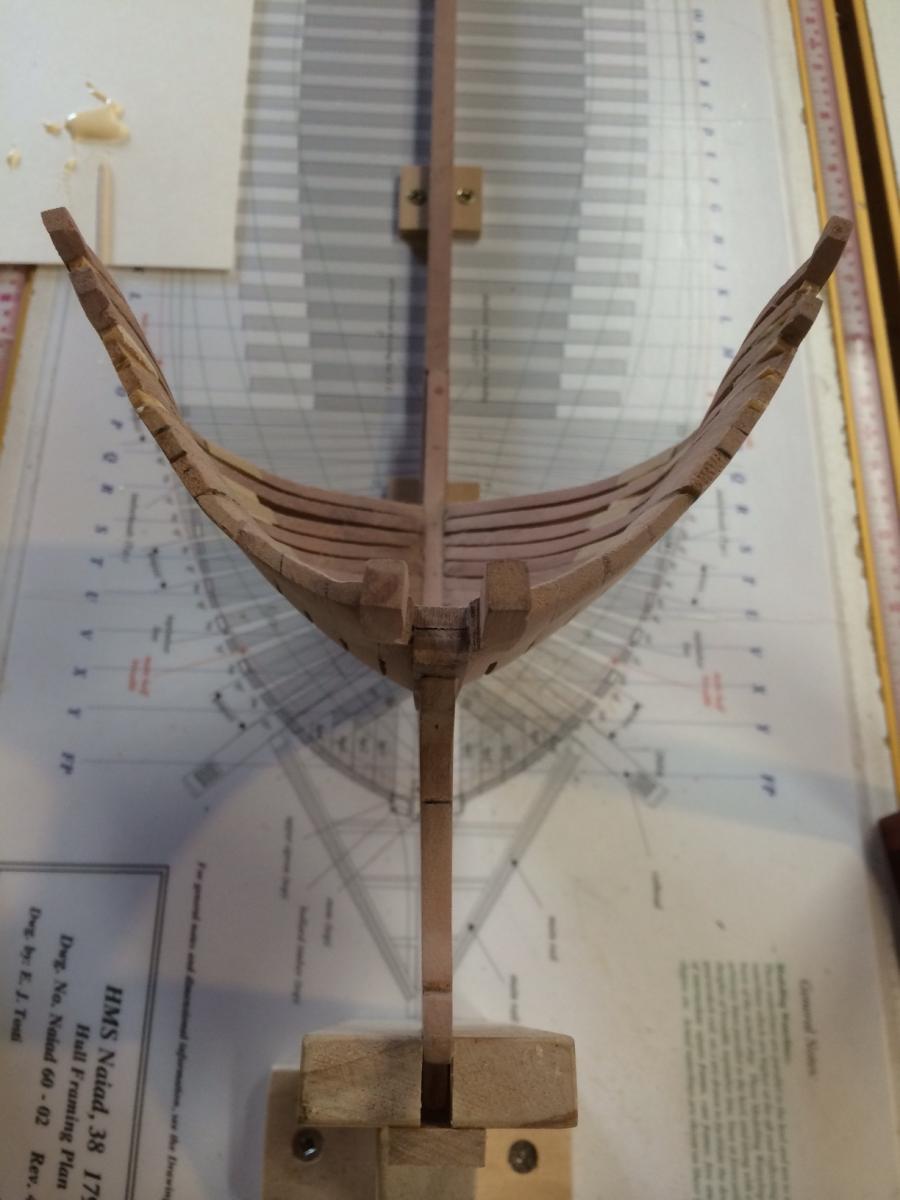
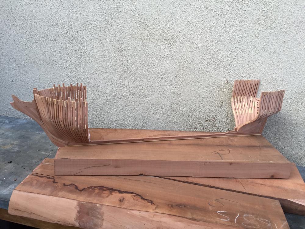
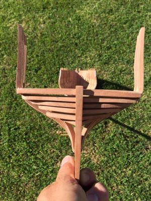
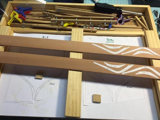
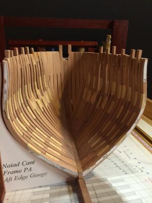
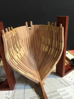
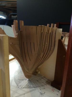
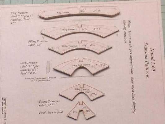
Good Morning - 165 hours into the build and feeling good! I have just four cant frames left in the stern (25f, 25a). At this point, I will have reached what I consider the fifth milestone. With such a long build, I have taken the advice of fellow modeler, Bill Edgin, who suggested that I break the build up into "mental milestones" so as to keep my enthusiasm up. Here are my mental milestons, which by no accident closely follow the layout of the books, Naiad, Vol 1 and 2 by Ed Tosti: 1. Careful studying the practicum, committing to the build, assessing the order of construcution, skills possessed and needed to be acquired - done 2. Erecting the building board, associated jigs and tools - done 3. Laying of the keel, stem, and stern posts - done 4. Bow, to include hawse pieces and forward cant frames - done 5. Stern, to include transoms and aft cant frames 6. Aft square frames (to midship) 7. Forward cant frames (to midship) 8. Stabalization of the frames and fairing the sweep of the hull 9. Thats enough for now... I expect the above to take me about 4-6 months. And now for the progress report: Here are a couple of shots of some frames. As you can see, there is a lot of template cutting that goes on with a build like this. I find this work to be enjoyable. You need to approach it in a logical fashion, or you will run into trouble quickly. There are upwards of 15+ pieces of wood in the frames once you start the square frame construction. The rough fairing process begins. Note that I use blue painters tape on the keel. I find this helps to mitigate any rounging that may incidentally occur while moving the piece to and from the jig. Keen eyes will note the accidental undercutting of the filler pieces as they meet the rabet in the stern post. This will get smoothed out, but could have been perfect if I had been more careful as to where my file was... The jig in action. These are "rework frames". I find that its just plain easier to remake an entire frame as opposed to trying to salvage sections when there are issues. I have also promised myself not to continue trying to put a square peg into a round hole. When something doesnt fit, I snap it in half and start over. Its actually faster that way. As fellow modeler Bill Sproul said to me at our Guild last week, "go slow for maximum speed". Naiad, sitting atop a newly arrived batch of swiss pear, awaiting milling. Awaiting final fairing. Good enough for now. Note how the transom pieces end at the rabbet. I am really happy with the symmetry and fit here. But still need a little fairing on the port side by the foot. The transom was an enjoyable challenge. I am debating about adding the filler frames that lay just aft of the aft fashion piece. I am a huge fan of showing work, so may leave these out so you can get a glimpse of the inner structure. I am still undecided, but will move on for now and revisit this once I begin the final hull fairing and finishing. Thanks for checking in, Gary.


-
Well done! I appreciate all the discussion on the rudder coat and will be using these ideas when the time comes in my own build. Thank you. Gary
-
Happy Monday! I am now 130 hours into the Naiad. Not a lot of progress this week due to my building a fort in the backyard for my kids. But in keeping with my Monday posting, here is the view of the stern transoms and filler pieces. You will note that I have begun to carefully fair these sections. At this point, I am just trying to keep things at a pre-finished state, recognizing that the final sand and buffing will come much later in the build. I feel that I have reached a point in the build where I know it will be successful. I say that cautiously, and what I am trying to say is that I can visualize the rest of the build as it should be. The stern and bow sections were especially tricky and despite this not being my first scratch project, I was still unsure as to how things should go. In the final sanding, the foot of the cant frames will flow into the cut down of the beardning line for a scale 2".

-
Greg, thanks for the tip on fairing. I am with you here. Albert, thanks for the kind words. I love your Naiad. The wood tones are beautiful and fit of your timbers is inspiring. Others - thanks for all the likes! I will post more on Monday. I am trying to post weekly on Monday. Having structure like that is a benefit to me. Now for those of you who are contemplating a first scratch build - I strongly encourage it. There are so many great practicums out there, including this one on Naiad. The end results are very fulfilling. If I can do it, then almost anyone with can - trust me here! Best, Gary
-
Hi Tim, Great start! I will follow along for sure! Your stem box joint and stern post look very crisp. Gary
-
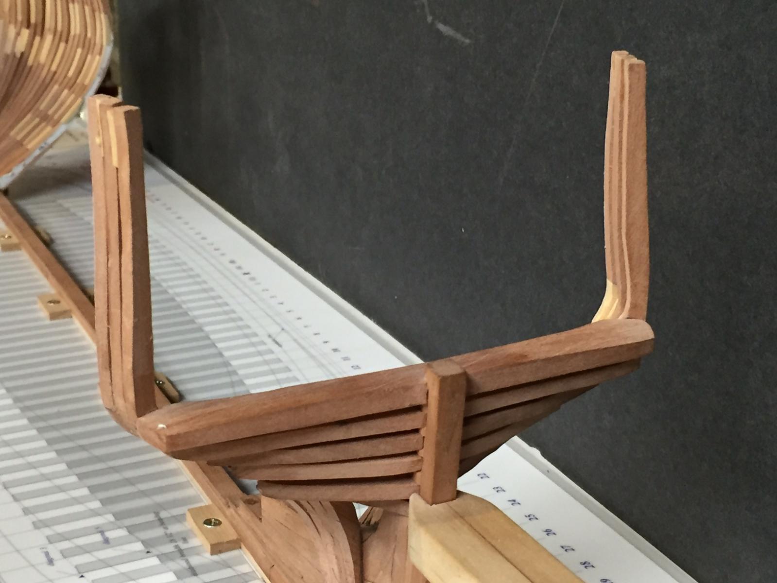
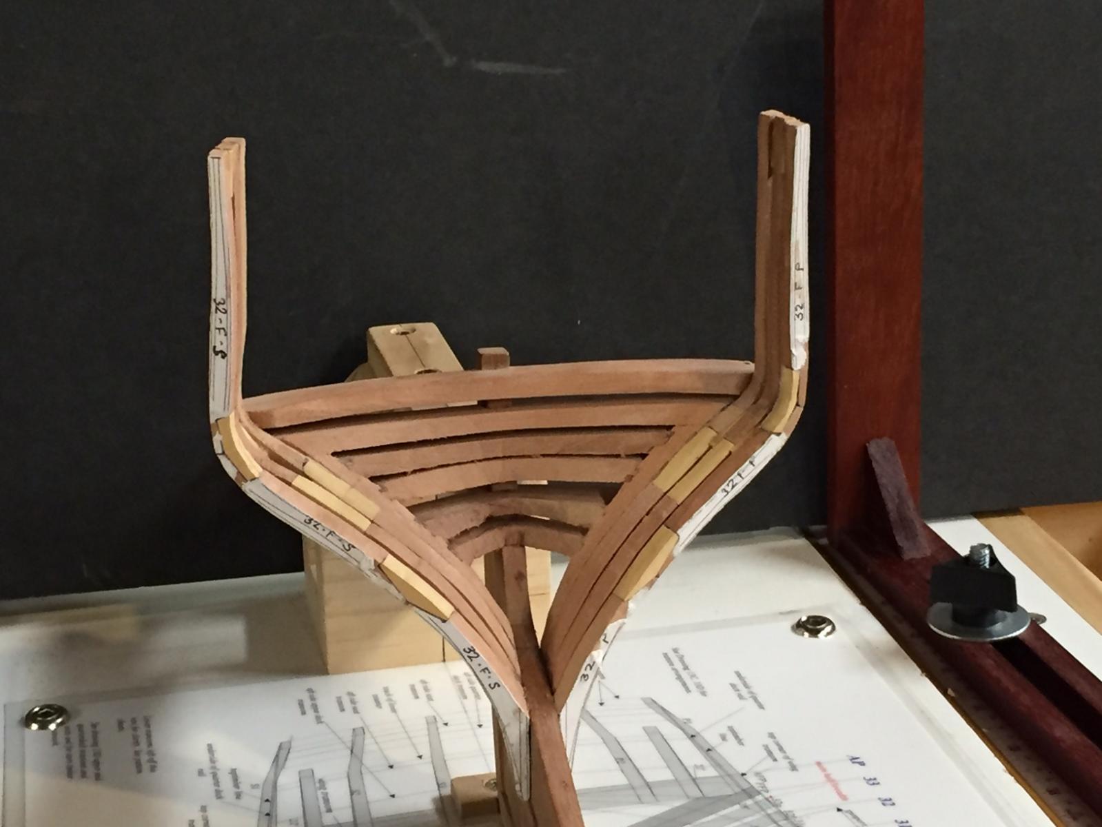
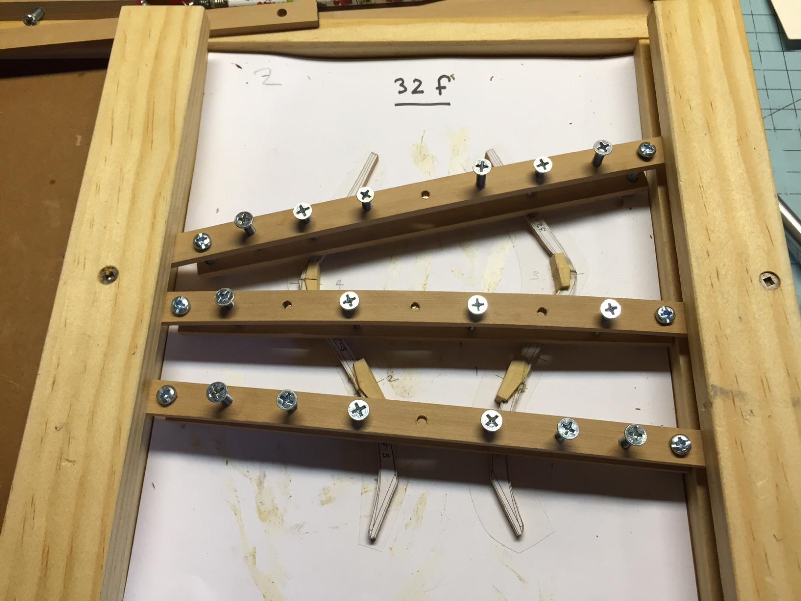
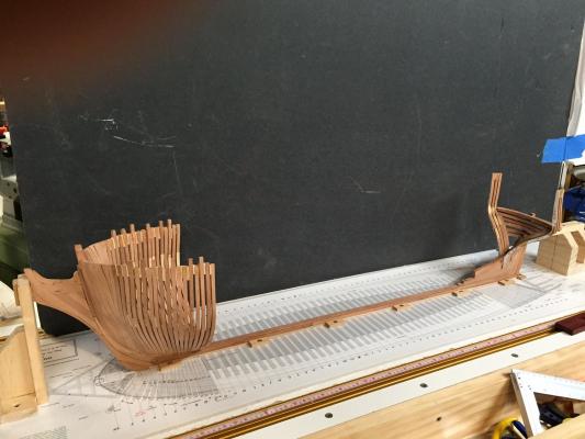
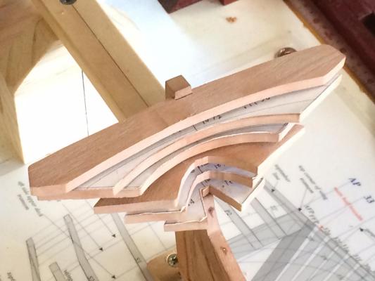
120 hours into the Naiad build. I am really enjoying this! Progress has been made on the transom and stern cant frames. Again, all final fairing is being deferred to later. A few shots of the forward fashion piece (ffp) prior to the transom pieces being faired. There is a lot of meat on these and with good reason. Note the dados from the filler and transom pieces. Also note the camber of the wing transom (top) as well as the deck transom. Ed shows some reallly nice camber clamps in the book, Naiad. I have yet to make these and know that I should (and will). They allow angled clamping. I made the straight clamps, which are great, but here, have settled on the plastic clamps. These are not ideal, but do work... Frames 32 forward. Each frame has an aft and forward pair, along with a template to match. It is issential to leave the templates on the frames until the last possible moment. I have gained more confidence in this build and have started to gently fair the frames to the template once installed. Note the transom and filler pieces have been faired here. Also, the chocks have been chiseled to thier final thickness and sanded, leaving the template mostly intact. Again, without the template, you are lost... Here are a couple of shots of my framing jig in action. This jig, as described in the Naiad book is a wonderful tool. Sure, you could get by without one, but the precision required for each frame makes this jig a worthy investment in time and energy to build. When making frames, I alternate between stock. I number my stock 1 thru 4 and build each frame from a different piece. This is the same principle for tiling a floor. Subtle changes in the color and texture will blend in much better with this method. Also shown here are the chocks, I number those as well and will split them afterward. Each chock is matched to specific frame location. When fitting framing pieces together, I will install the chock on one side of the frame (not shown), clamp, let dry, chisel to thickness and then paste it to the template on the jib itself. I then match up the other side of the frame, carefully beveling the frame to match the chock as well as inside and outside lines. Once done, glue in place, clamp the frame down and then clamp the chock. The next day, I fine tune the frame. Book mathching (not shown) the cant frames is a good quality check. If they are not equal, either tweak them or chuck them... I do a gently sanding using a drum sander just to smooth out the rough frames. Most of my fairing is done with miniature cabinet scrapers and I find that a smooth frame scrapes best... A couple of shots of the full project. My landlubber neighbor came by yesterday and said, "Its starting to look like a ship". I took that as a compliment. To me, it looked like a ship after the first piece was made... The aft faces of the transoms and filler pieces from the stern will get rough faired this week. I will repaste the wing transom template as a guide.


-
Hi Jerrry, I just came across your build and will follow along for sure! Beautiful framing - crisp and accurate. Gary
-
Cutter Cheerful 1806 by rafine - FINISHED
GDM67 replied to rafine's topic in - Build logs for subjects built 1801 - 1850
Allow me to jump in here as well. Crisp execution of every step. A pleasure to look at and read. Gary- 525 replies
-
- 3
-

-
- cheerful
- Syren Ship Model Company
- (and 1 more)
-
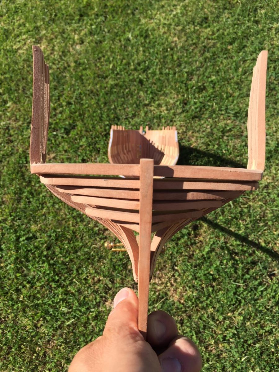
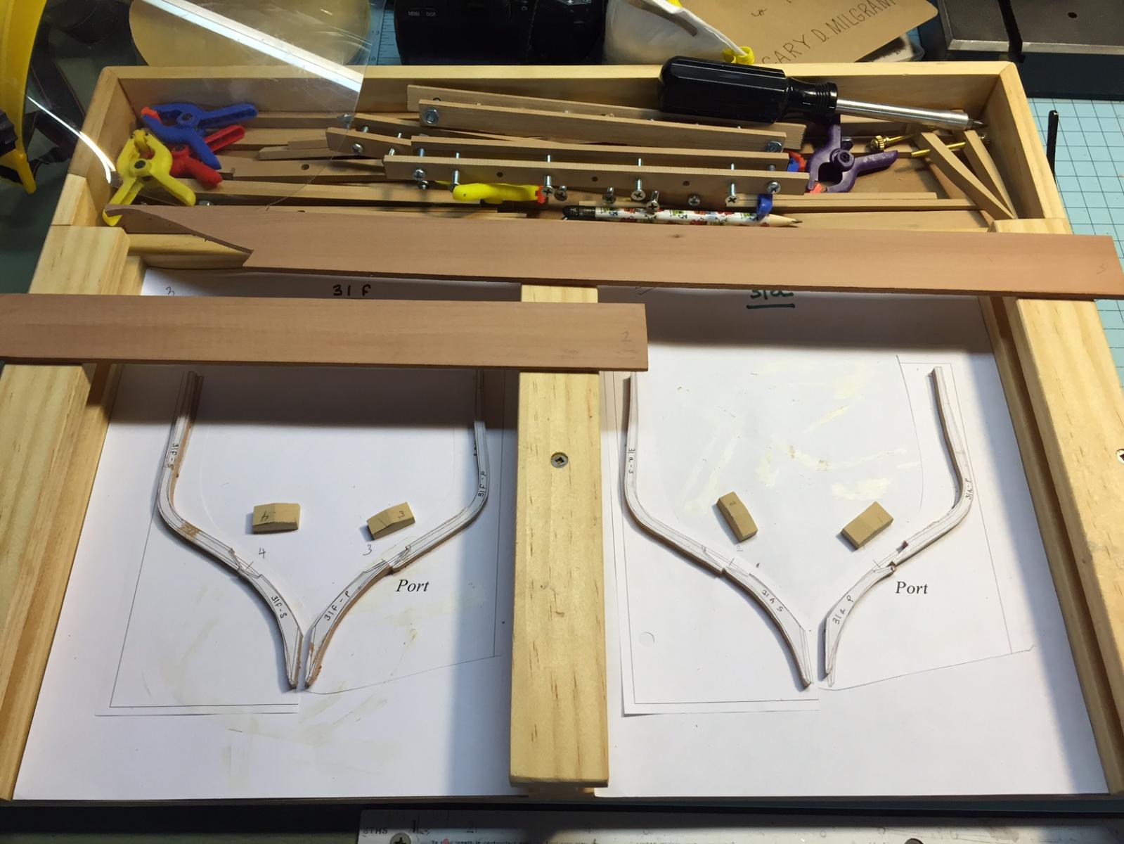
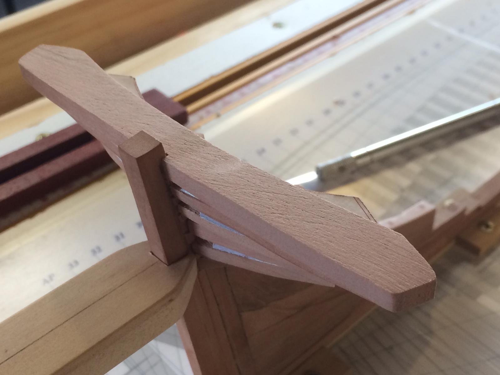
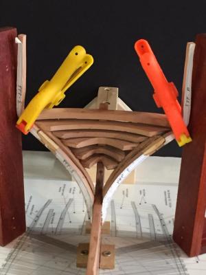
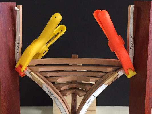
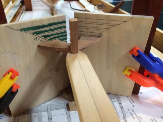
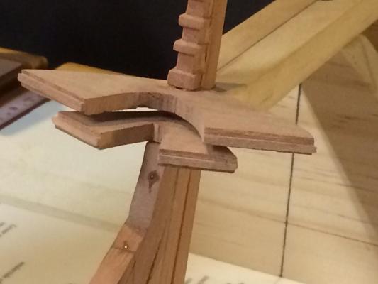
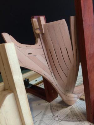
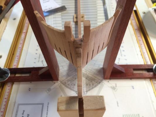
106 hours into this build. I have now completed the installation of the forward cant frames. This is frame "p" forward. I am pleased with the results and will hold of on further fairing and finishing until all of the frames are installed. I am now turning my attention to the transom and the aft fashion piece. This area presents another challenge and is well described in the book, Naiad. Since I dont own a mill, all of the work is done the old fashion way. I had to redo the transom pieces I made earlier in the build since these were cut a hair short of the aft fashion piece where they need to dado in. Boy, close up photos are no fun. The pieces actually look better in person... The goal here is to get fashion and filler pieces 1-4 to be on the same vertical plan. The aft fashion piece will then have dados in it to accept these pieces. Once complete, there will be considerable fairing to get to the finished product. Above are the verticle templates used to align the fashio pieces. I marked the afp on these uprights as well as all the intersection points.
-
Hi Ken, Your Rattler is looking great! I build one and enjoyed it greatly. I love the buckets, a very nice touch. Gary
-
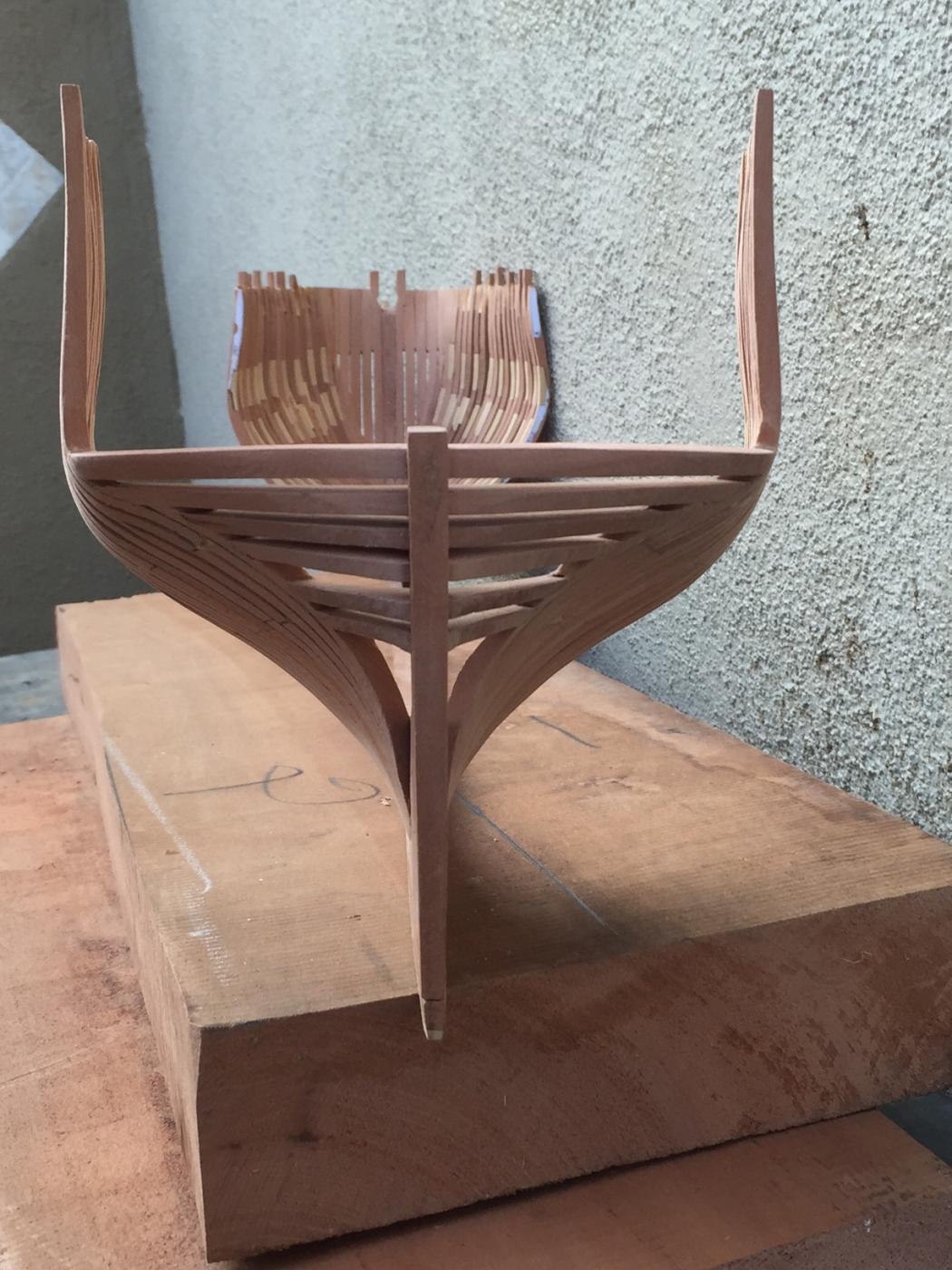
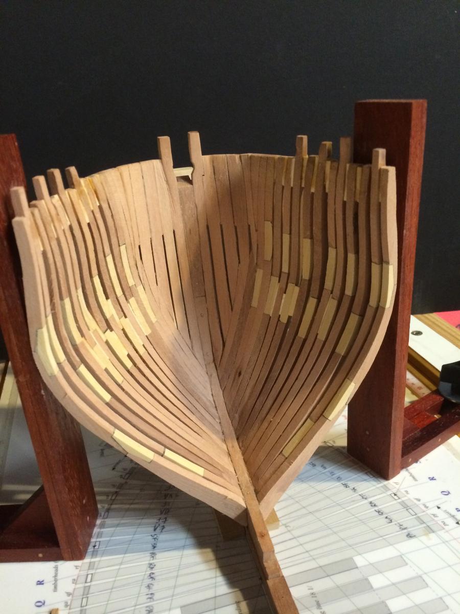
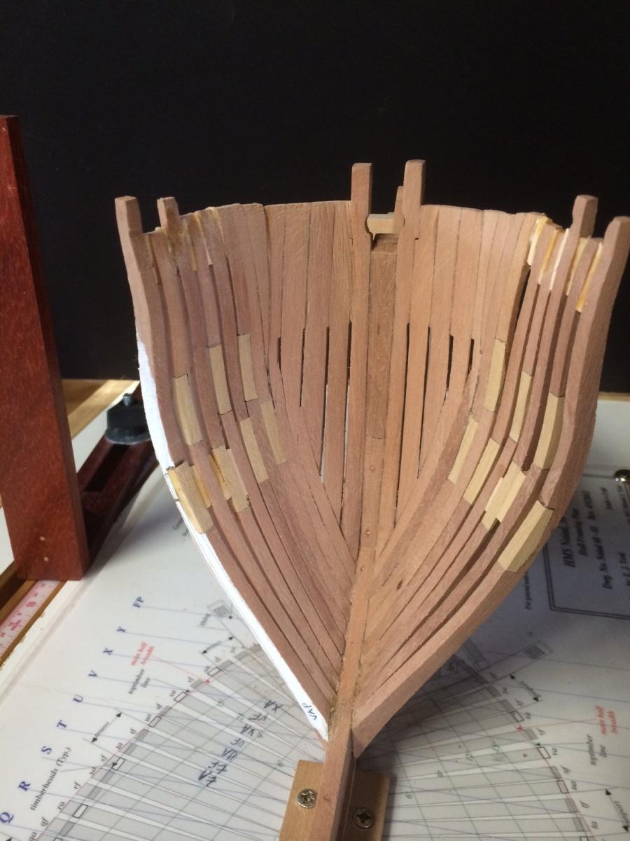
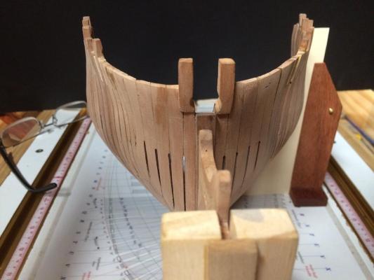
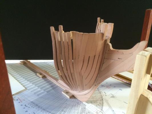
Mike Y, thank you for your kind words. I enjoy writing this log and glad you and others enjoy it. This week, I have made steady, but slow progress on the Naiad. I am about 90 hours into the build and still get in about an hour a day. Its mostly in 20 minute blocks that I get to work or after the kids go down, so I am either distracted or tired. But thats what it is and if I want to build, then I need to accept it. Below are photos through frame s. You will note that some of the cant frames now require two chocks each. You will also note that the top timber is no longer the reference point for setting up the frames. The maximum height of breadth is used to do the intial placement of the frames at this point. I simply fair the outside aft edge of the frame to the maximum height of breadth and line it up with the upright jig. Once the glue has set, I use the frame template to make sure I am on track. Spacers are added after the frame has set. Using a triangle, I make sure the frame is perpendicular to the keel and aligned with the base drawing. The photo makes the frames look skewed on the port side, but they are actually in balance. You will also note that there is a lot of wood still left between the upper and lower heights of breadth. This will be faired after I install the gun port sills. I dont want to thin them too much prior to this. I will simply fair to the moulded dimension of the sills at that time. I am tempted to cut the gun ports in now, but Ed advises against that. I think it has a lot to do with alignment at the top timbers. So, I will wait... I purchased a set of mini cabinet scrapers that I use to fair the inside. Again, everything is rough at this point. As we all know, once you take it off, you cant put it back... I expect to be done with the bow cant frames by the end of the week and will begin the stern transom and cant frames after that. I have developed a pretty good rythm with building frames and use a just-in-time approach as Ed describes in his book, Naiad. I find that building each frame one at a time is not the most efficient way to go, but it does lend to better quality for me and also allows me to keep the pieces all together. More next week. Thanks for reading. Gary

-
Hi "navymast", your translator program is working just fine. Where are you from? I think one of the greatest asects of this forum is our ability to connect to enthusiasts all over the world. Best, Gary
-
Beautiful build thus far. I will follow along. Thanks for sharing. Gary
-
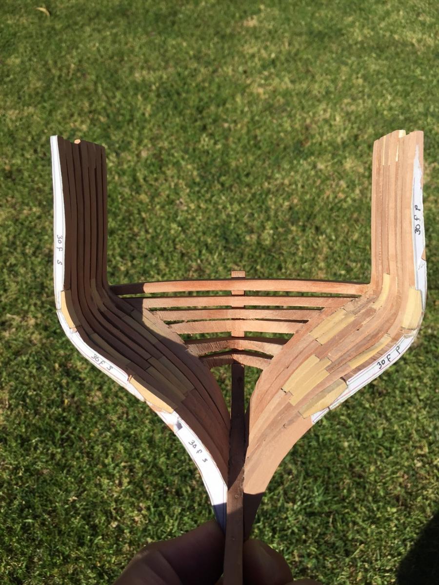
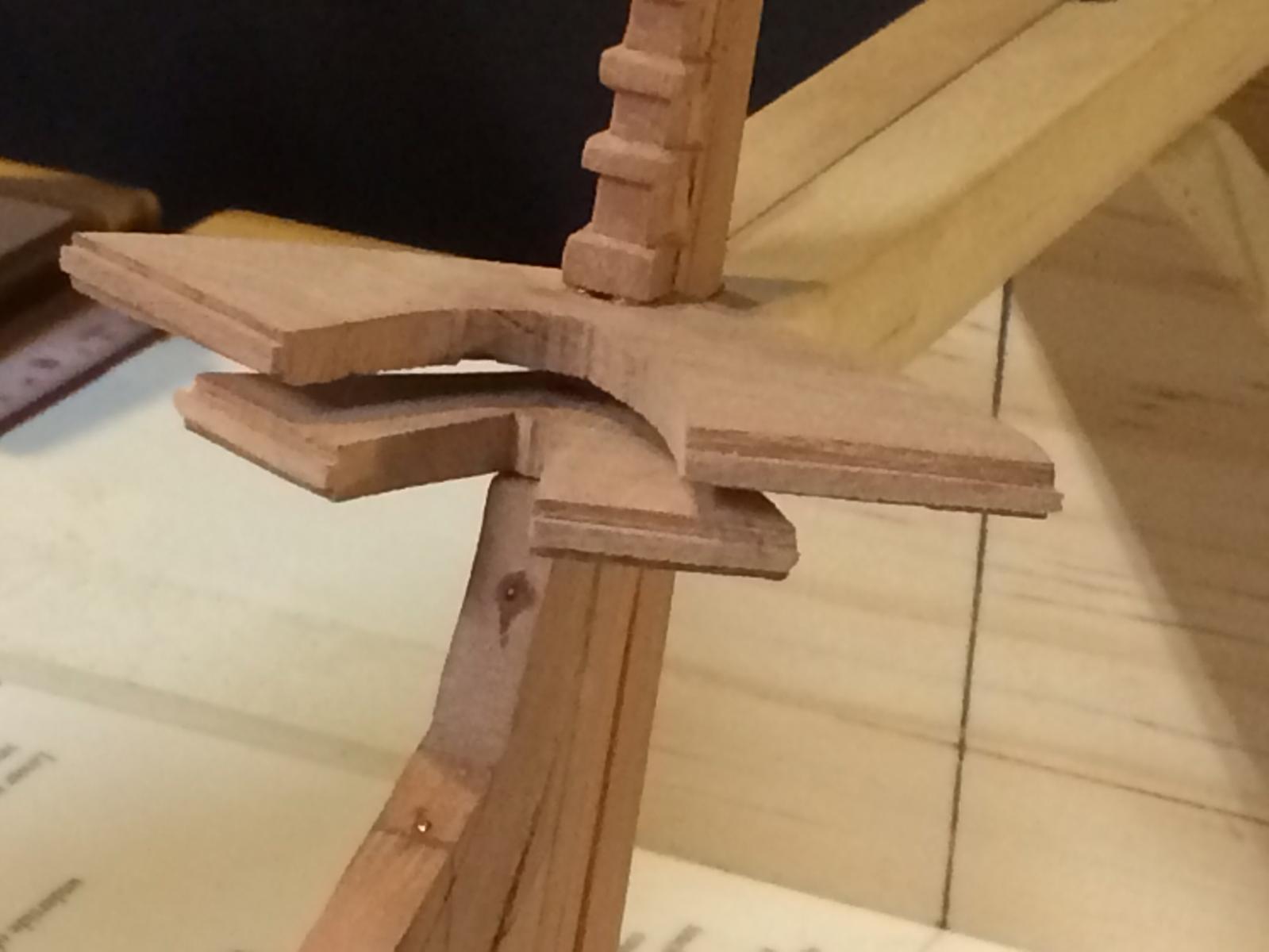
Hi All, More progress on the forward cant frames. The below photos show the from frame "t" forward. I am very pleased with the results. Note the West Indian Boxwood chocks from a sample piece of wood courtesy of D'Lumberyard. The framing template also lines up with the aft edge of frame t. As you can tell, there is still some fairing to be done, especially at the belt line where the frames are far too thick at this stage. That majority of that fairing will likely come from the inside. Here is the port view. You will note that I still have to trim the top timbers. They will get their final sizing when I do the final sanding. In a future post, I will show a close up of the footings of the forward cant frames. This area is a bit complicated - and was a challenge to do. It all makes perfect sense now. I am speaking of the area where the forward deadwood, lower apron and keel come together as an assembly to receive the frame feet. I will also do a step-by-step of a frame assembly. Ed speaks about developing processes that will ensure success. While I follow those from the book, I have individualized mine to meet my skill and comfort level. When I deviate from the process, thats when the work quality decreases... Interesting observation... G

-
Hi All, thanks for the likes and follows. Ed - I appreciate the advice and will put it to work. More to come. G
-
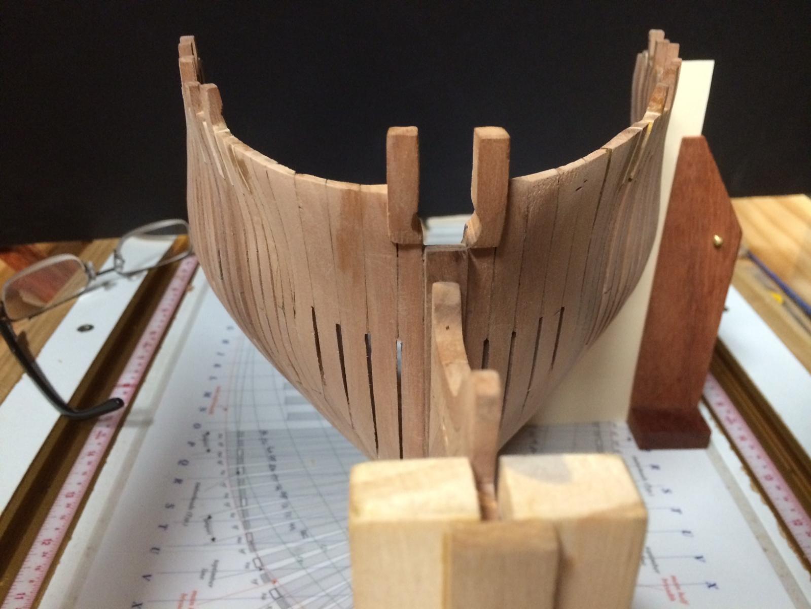
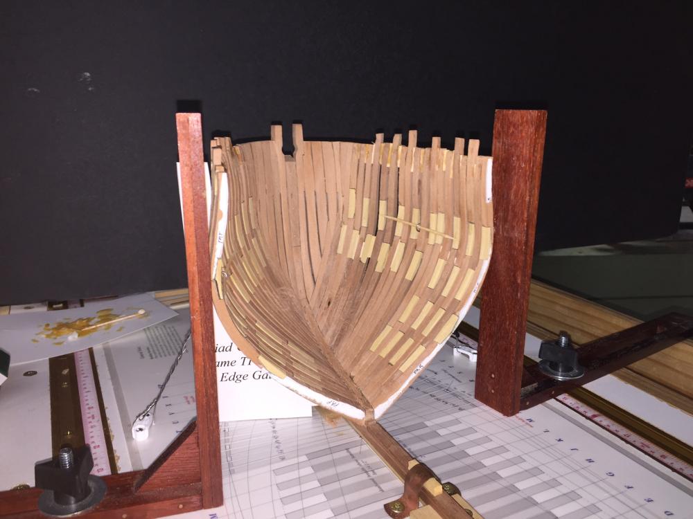
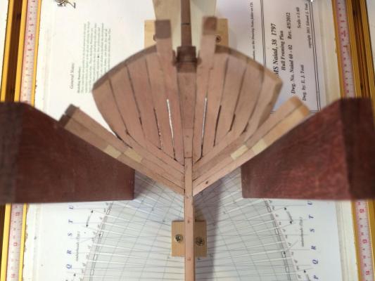
The bow of this ship has certainly been a challenge. Here she is, still very much in the rough. I have installed through frame V. The sheer line still needs to be defined, but I will worry about that later. I experimented with a yellow Titebond woodglue that I am not a fan of. Switching back to Elmers Carpenter - a white glue for the duration. At this stage, I am 72-hours into the build, again, averaging about an hour or so each day. You will note that the template is still on the port frame V. As per the book, I am trying to keep the templates on as long as possible. The shape of the bow at the sheer line has turned out a little sharp. I plan to correct this in the planking stage. Otherwise, she is symmetrical.


-
Brig Eagle by robnbill - 1:48
GDM67 replied to robnbill's topic in - Build logs for subjects built 1801 - 1850
Bill, she is looking spectacular. Chain, barrels, treenail details. Its all coming together wonderfully. G -
I am now 60-hours into this build and am exceedingly happy with the results. This is the first time I have tracked my hours in a build and I actually like doing so. I average about an hour a day. My goal is to get into the shop for atleast a few minutes each night, which usually turns into more. This tactic has kept me fresh and keeps progress steady. Understandably, I took very few pictures of the rework and am finally on to new stuff. Below is a shot of the port bow. Please note that everything is in the "rough" at this stage. I will fine tune later - yes, this drives me crazy... The air gaps still need to be cleaned out and filed straight as well. The shoe should be thinner than it is here. I missed that tiny detail, but its small. Note the absence of Hawse Timber #5, that is yet to be done. An interesting detail to note is the size of the stem as compared to the knee of the head. Note the subtle taper? These are the kind of details you get in an authentic scratch build. Obsessing about these things is a passion. Note the use of the uprights in aligning the toptimbers to the base drawing. The photo shows them just slightly off due to the angle of the shot. They are dead on. There still needs to be some slight tumblehome added to these hawse pieces. There are templates to help with this. Here is a shot from the inside. I used boxwood chocks to contrast the swiss pear frames. Most of these will not show in the final product, but I will be spending a lot of time with this build, so I wanted them to look pretty. The last show is of the first free standing cant frames. I will put temporary pine spacers to secure them in place as Ed describes in the book, Naiad. You can see how the framing square and uprights are used to ensure the frames are both perpendicular to the base line and the toptimbers are on the mark.
-
Palladio, where to begin... Superb modeling, techniques, how to's, wood choices, overall color tones, subject mattter and photography. The mouse is exceptional, as are the long guns. Its inspiring. G
-
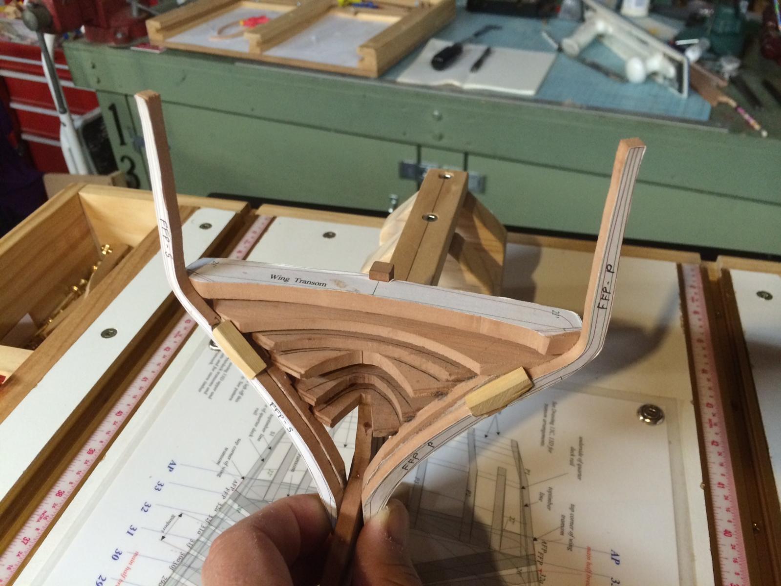
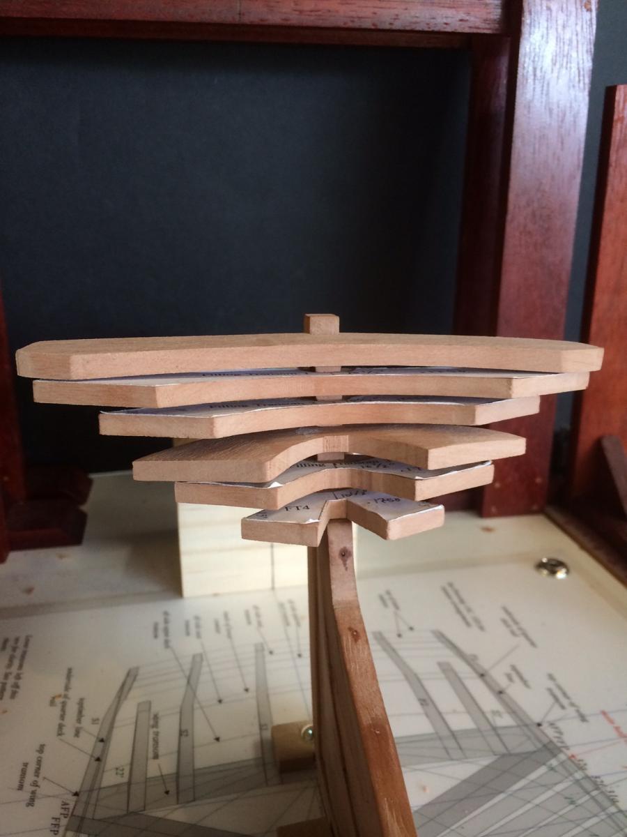
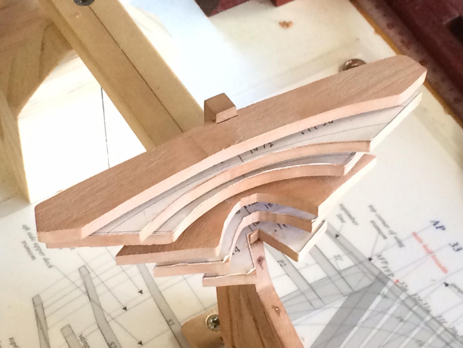
Hi All, I have almost finished the rework. I estimate it to total about 50-hours... That being said, I am still very happy with the decision and have corrected some previous mistakes. While I still need to work the hawse pieces, I needed a change of pace and elected to start the transom. This section is very tricky since its a true puzzle and everything is inter-related. Above are the six main pieces to the transom. You will note that I put the size of each piece on the template. There are two pieces, the wing and deck transoms that require 4" added thickness because these pieces require an arc shape to them. The Wing transom will set the shape of the stern and the deck transom will curve with that deck. At this stage, I am not worried about fine tuning the pieces, this is not an excuse to be careless or sloppy, you just want to leave a little meet on the bone and trim it later... Here are a few other views - these pieces are dry fit and will be aligned with all sorts of jigs and glued spacers when the time comes. They still need to be fine tuned. The wing transom needs more arch. You will note that I have left the templates on as well. Ed recommends this in his book, Naiad, and I think its important. If you lose your way with a piece, your puzzle wont fit together. The templates keep you honest. All of these pieces need to tenon into the sides of the aft fashion pieces, which will be tricky to say the least... In the below photo, note how the aft portion of each piece ends at the rabbet of the stern piece. I envision the planks nesting tightly into that rabbet. This will all need to be faired once glued in and well supported. I have to remind myself to not get carried away with fairing at this stage...


-
Your planking is looking very nice! Symmetrical and well faired. G
- 25 replies
-
- 2
-
-
- snake
- caldercraft
- (and 1 more)
-
Hi All, So... I am specifically referring to canted frames. I took a simplistic approach which was to finish size the frame to the pattern that was pasted on it and then I would paste the mirror image of pattern to the back. What I am specifically looking for is the angle of the foot. I had a hard time getting this to the 34.5 degrees as stated in the practicum. I used the back pattern to help me establsih the line (angle) of that foot. As for beveling of the futtocks, I dont think this is necessary to do all of this and I can see how that would be extra work. Hope that clarifies. And, I really appreciate the dialogue. G