HOLIDAY DONATION DRIVE - SUPPORT MSW - DO YOUR PART TO KEEP THIS GREAT FORUM GOING! (Only 20 donations so far - C'mon guys!)
×


Jared
-
Posts
305 -
Joined
-
Last visited
Content Type
Profiles
Forums
Gallery
Events
Everything posted by Jared
-
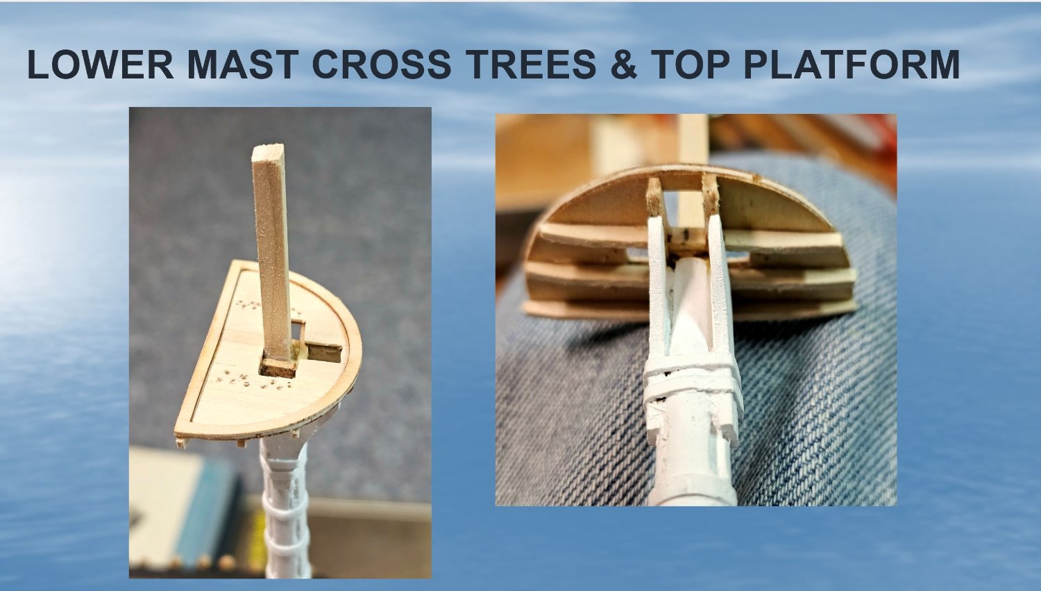
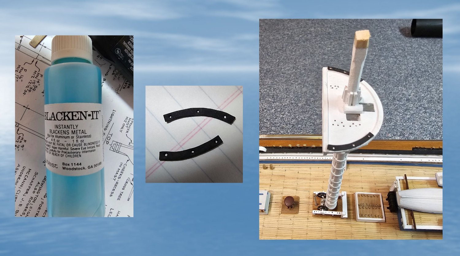
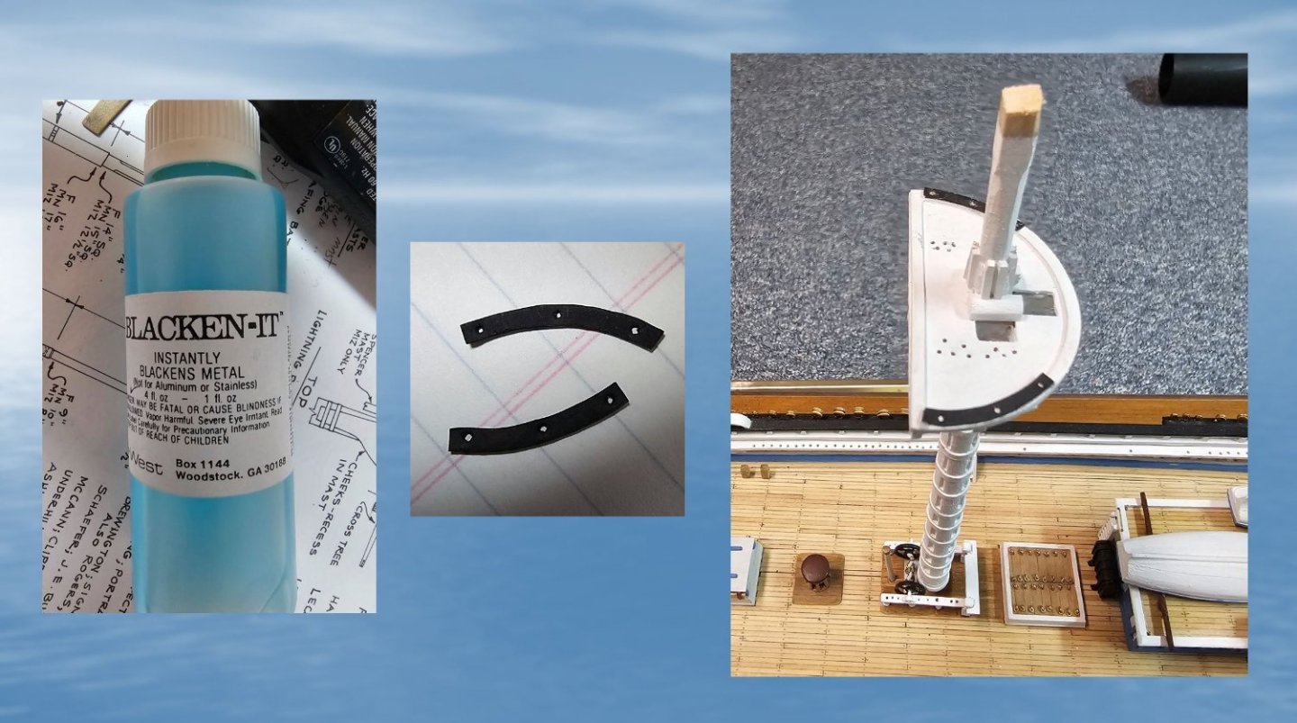
Another quick update. Between other summer distractions I continue to work away on the construction of the lower masts and Lower Mast platforms. The following 4 images show the recent progress. The metal plates on the platforms were cut & ground to shape from sheet brass and chemically blackened.

- 431 replies
-
- 3
-

-
- Flying Fish
- Model Shipways
- (and 2 more)
-
Thanks for the heads up on the chain and other needed accessories George. Your model looks fantastic. I wish it was as easy to build as you make it look 🙂
- 602 replies
-
- 1
-
-
- Flying Fish
- Model Shipways
- (and 2 more)
-
Thank you.
-
At the end of the day, with lack of any photos of the actual FF, who is to really know perfectly our models match the real deal. 😀 Best regards, Jared
- 602 replies
-
- 1
-
-
- Flying Fish
- Model Shipways
- (and 2 more)
-
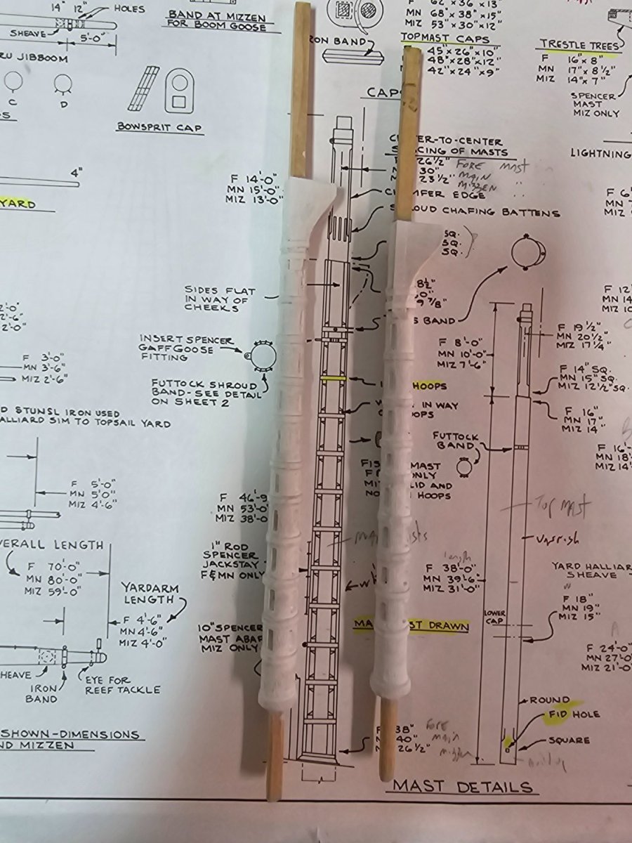
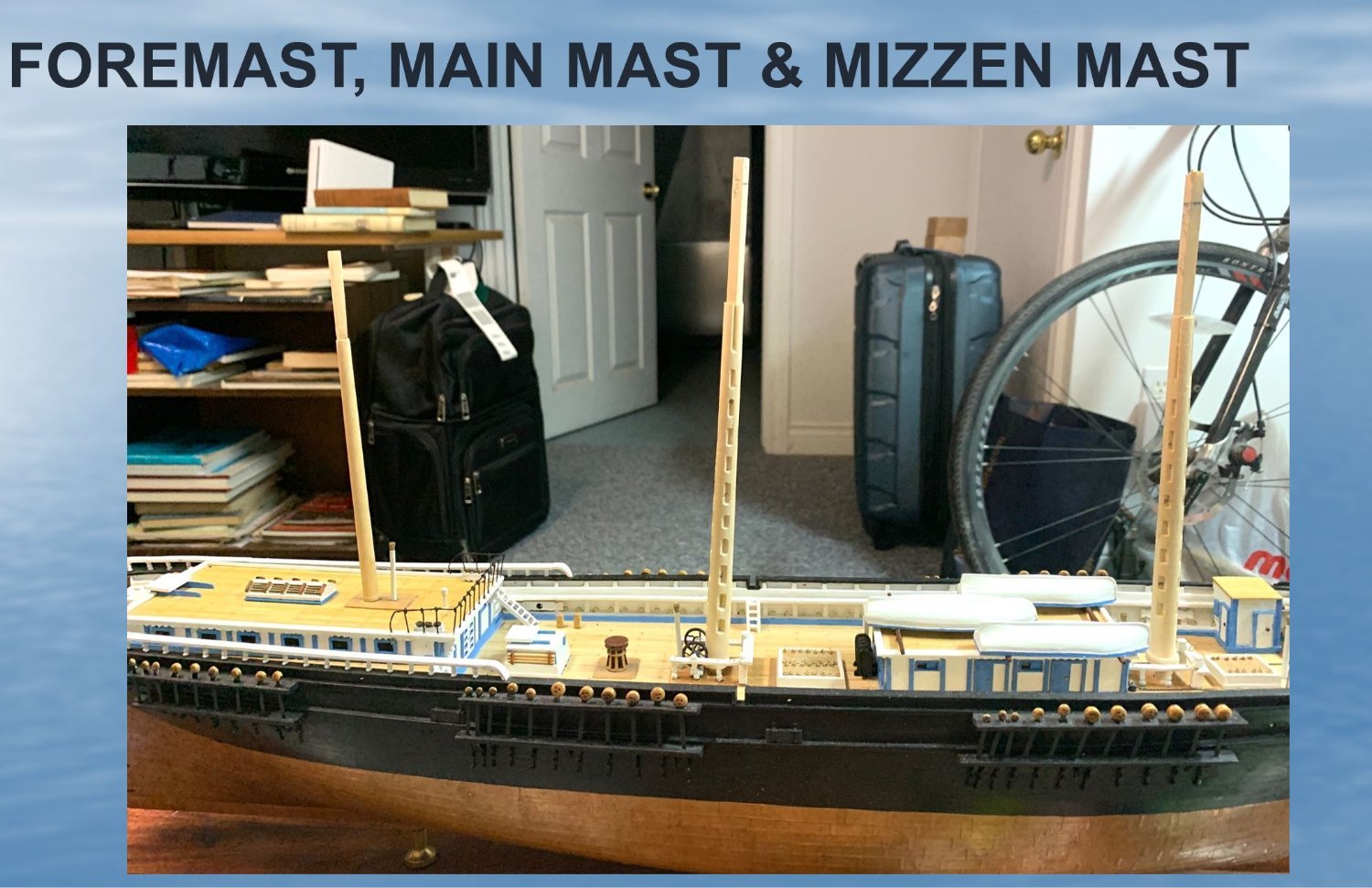
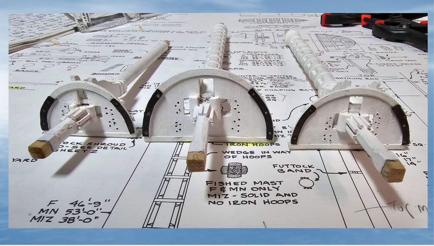
Just a quick update. I have completed much of the lower fire and main masts, as shown in the attached photo. I elected to construct the iron bands for these masts using my wife's business card, which had the perfect thickness (0.016"), was easily cut into 1/16" wide strips, and was smoothly bendable around the masts. They were glued to the mast using CAA gel superglue then painted over. The wooden cheeks were the shaped and mounted.m

- 431 replies
-
- 2
-
-
- Flying Fish
- Model Shipways
- (and 2 more)
-
This is a great discussion. I am presently struggling with whether or not to put hoops on my solid mizzen. My gut feeling is to go with out the hoops as per the Langford plans, based on something I read in "China Tea Clippers" by George F. Campbell, a caluable resource. On page 112 Campbell writes "Whenever possible wooden lower masks were made from a single tree . . . . . The mizzen mast, being relatively small, was usually a single tree. ITS SMOOTH SURFACE WAS ALSO CONVENIENT FOR THE HOOPS OF THE SPANKER SAIL TO RIDE UP AND DOWN ON, AS ALSO THE GAFF JAWS IF SO RIGGED.
-
Very impressive workmanship George. The yards are looking great!
-
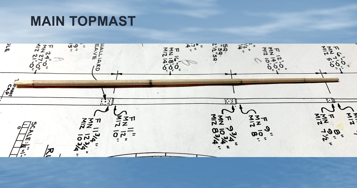
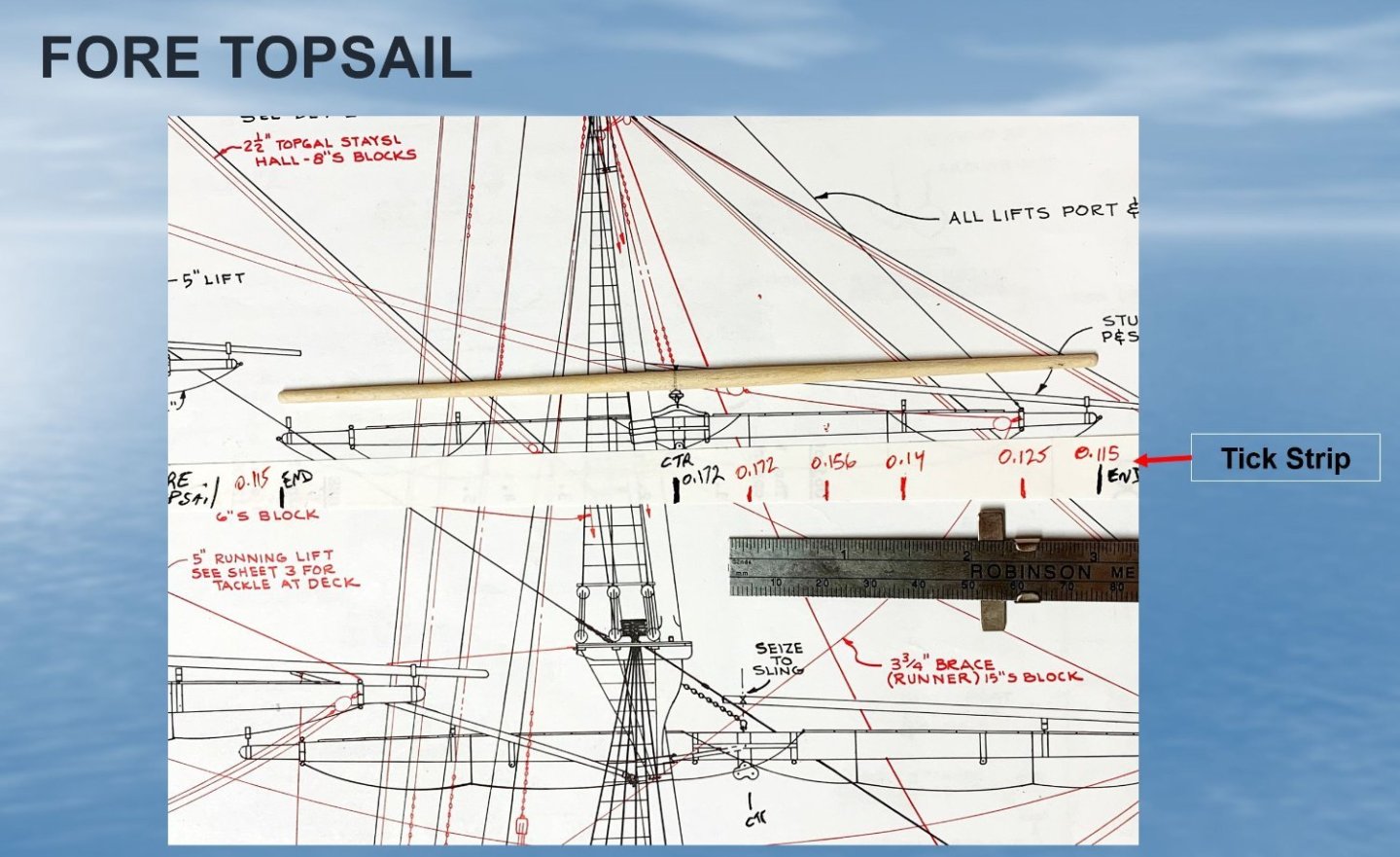
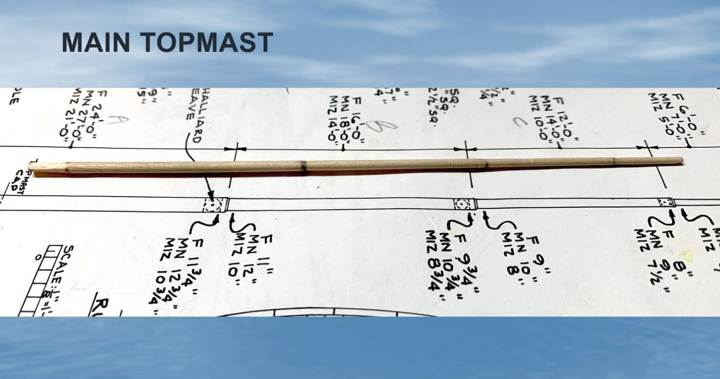
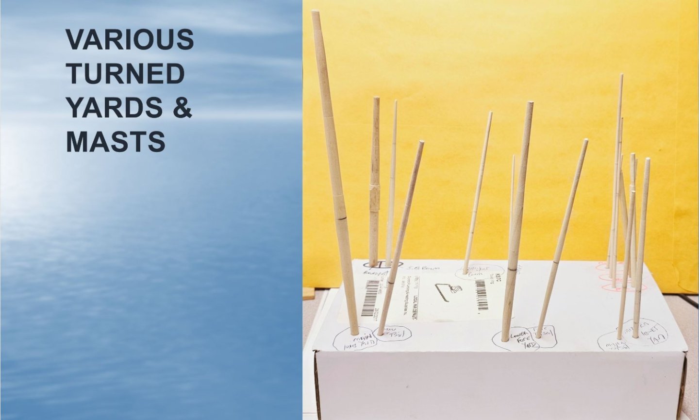
I have completed the turning of all of the wider diameter masts, yards, bowsprit etc. For these I measured from the drawings their diameters at various locations and marked these to tick strips. The pieces were then turned on the Taig micro lathe. At diameters below about 0.12", the pieces had to be sanded down to their final sizes otherwise they would break.
- 431 replies
-
- 1
-
-
- Flying Fish
- Model Shipways
- (and 2 more)
-
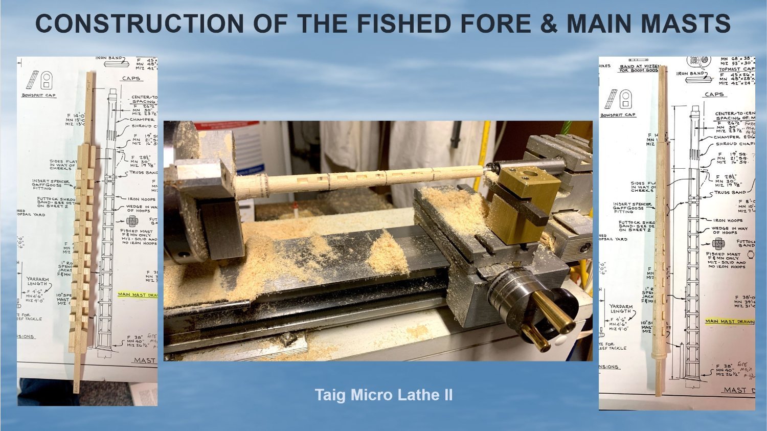
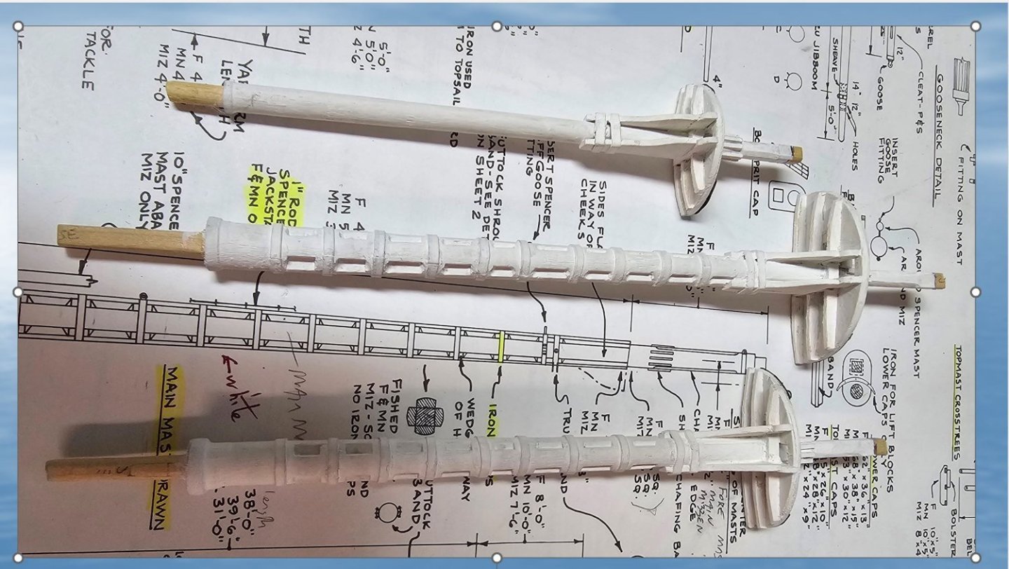
After a long absence due to travel and other distractions that get into the way of model building, I have picked up my model again and have been working on the construction of the masts and yards and bowsprit. For the fabrication of the fished fore and main masts I followed the method George (gak1965) so nicely described. I think the carving method suggested in Fig. 65 of the manual is very difficult and would have turned out terribly had I tried that. After gluing together the wood pieces making up the structure, I turned the wood on a Taig Micro Lathe II which a friend from my local shipbuilding club generously lent to me. The first photo below shows the construction of the Fore mast. The second shows the turned mizzen, main and fore masts. I have not yet started adding the metal bands or anything else on these.


- 431 replies
-
- 2
-
-
- Flying Fish
- Model Shipways
- (and 2 more)
-
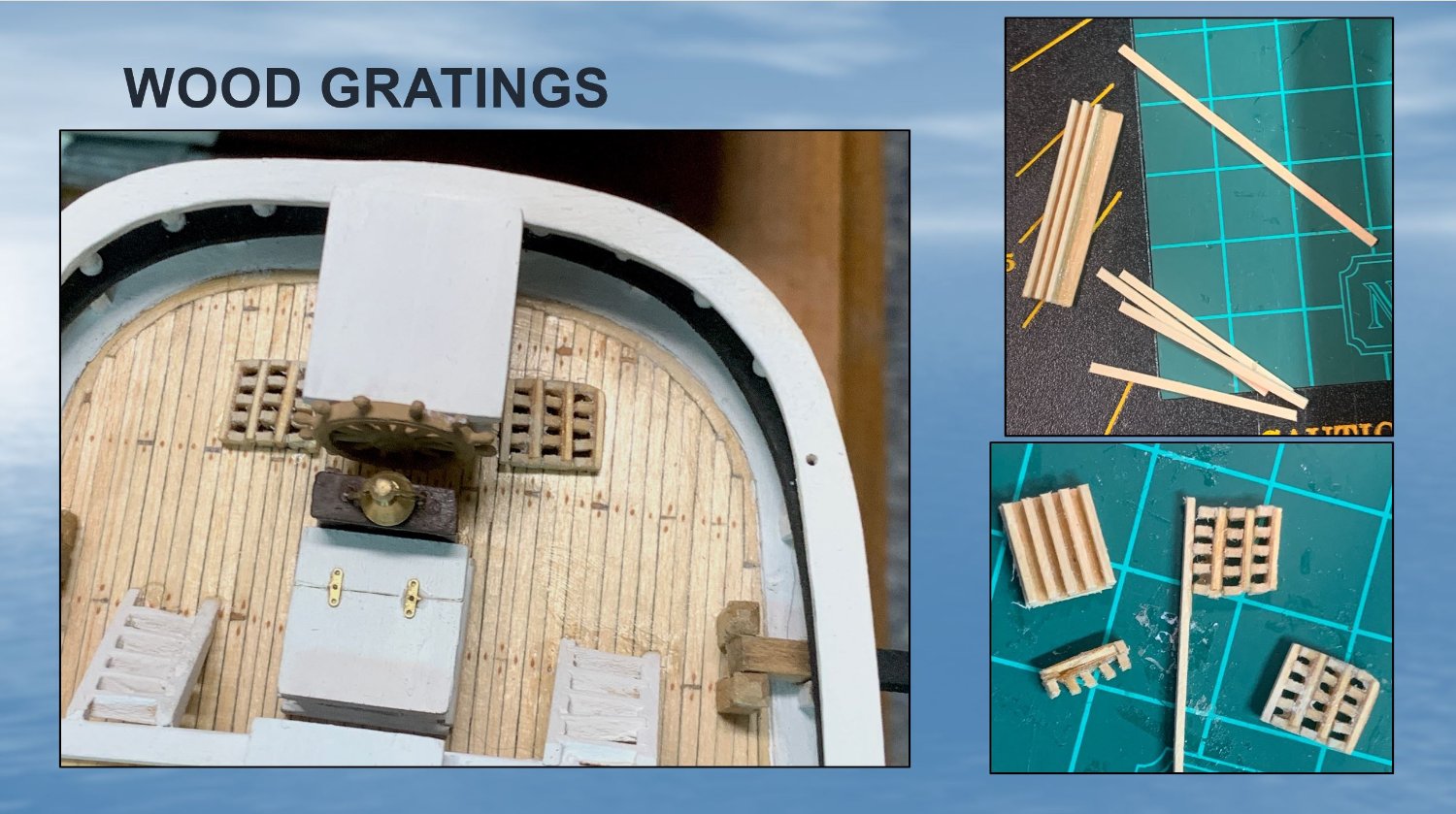
Today I completed one of the more challenging elements of model so far - the wood gratings that lie on the aft deck adjacent to the ship's wheel. At the scale of the kit, I thought the two suggested build techniques illustrated in the manual to be near impossible to actually do. In doing a search for possible alternative methods, I came across an interesting technique described in ModelShipBuilder (www.modelshipbuilder.com/page.php?128) which I decided to give a try. The photo below shows the finished result and two images of some of the intermediary steps I followed. It was pretty challenging as the cut parts were exceedingly small to handle and were very fragile to cut and shape.

- 431 replies
-
- 3
-
-
- Flying Fish
- Model Shipways
- (and 2 more)
-
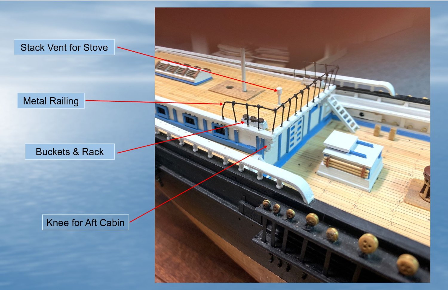
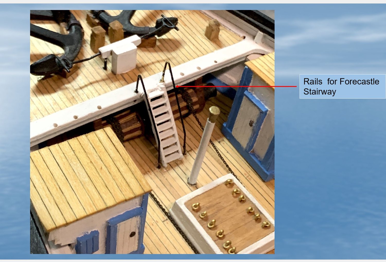
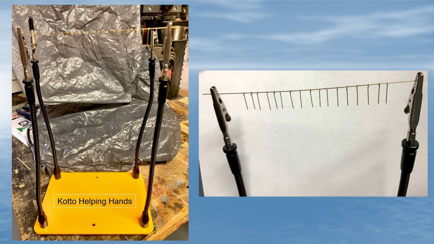
I picked up on my model again after an almost 8 month "rest" due to some travelling, etc. This week I completed and mounted several poop deck structures: bucket and racks, stack vent for stove, knee for aft cabin, and the metal railings on the Poop Cabin Roof and on the ladder to the forecastle deck. The stack vent had to be scratch built, as the metal part was missing from my kit. The metal railing on the Poop cabin roof was made by cutting pieces of brass rod (0.02") then soldering them together, using a handy Kotto Helping Hands soldering tool to hold the parts while I soldered. The railing was then bent to shape and mounted and glued into holes I drilled into the top of the poop house roof overhang. The railings on the ladder to the forecastle deck was also made from the brass rod, bent to shape.


- 431 replies
-
- 4
-
-
- Flying Fish
- Model Shipways
- (and 2 more)
-
You model is looking really good. Your photos and George’s will be a great help as I attempt to get started on my masts this month.
-
You have done an amazing job on your masts George and the wealth of valuable information you have provided will be a valuable guide to me and others. I have not made any progress on my model over past 3 months due to other activities and a honeymoon. Your work will inspire me to get going again!
-
Thanks for this
-
It would we great to see the catalogue photo. Thanks. I had no idea that the Chinese painting existed.
-
Nice progress. Don’t know the answer about the boats.
-
Thanks George. I have decided to orient the boats as per the plans and Butterworth’s painting. As to how I will tie the 3 on the cabin down, I will probably deviate slightly from the plan, depending on my skills.
-
Thanks ClipperFan. Love this photo. As an expert model maker I know told me, mounting the heavy ships boats upside down on the cabin roof makes for a lot more work to launch them. Although the boats are mounted upside down in Butterworth’s painting, I am wondering if this was really correct.
-
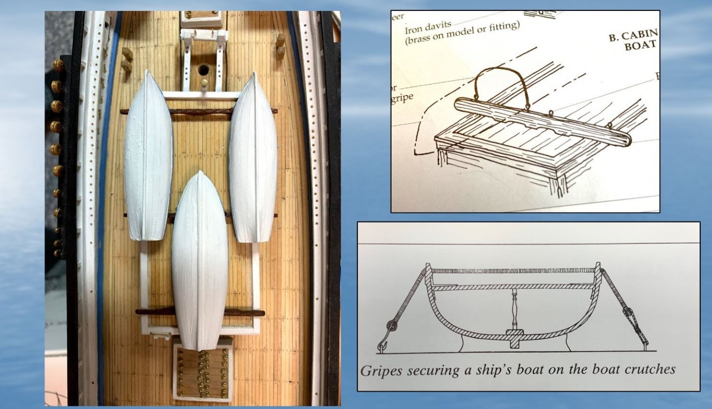
I have finished scribing and painting the outside hulls of the 5 ships boats and have mounted 3 of them on top of the mid-deck cabin (see photo). The problem remains on how they should be tied down to the support racks. In the kits instructions, they seem to suggest securing them with ropes whose ends are both eye-spliced around eye bolts (see top right photo), but this begs the question of how the boats could be untied when needed. I found a more plausible design in zu Mondfeld's book (bottom right photo). Any thoughts? Thanks. Although hard to tell from my image because of the photographic angle, the top trim of the ships boats have been painted light blue, to match the trim on my model.
- 431 replies
-
- 3
-
-
- Flying Fish
- Model Shipways
- (and 2 more)
-
Thanks. I had intended to paint the top trim. They were black before I rescinded the boats.
- 431 replies
-
- 1
-
-
- Flying Fish
- Model Shipways
- (and 2 more)
-
Thanks for your positive feedback Grey. Following up on ClipperFan's helpful feedback on my scribed ship's boats, two of which I had before already scribed incorrectly, I went into damage control mode to see if I could improve upon what I have done. Using model puddy I filled incorrect lines where I could and then did my best to scribe new lines that conformed better to general shape of the 2 boats. I think they are new better than they were, but not perfect. Scribing the lines on such a small curved surface isn't at all easy! Fortunately the human eye does not have the resolution to pick up all of the small imperfections that the closeup camera does below 😃

- 431 replies
-
- 2
-
-
- Flying Fish
- Model Shipways
- (and 2 more)
-
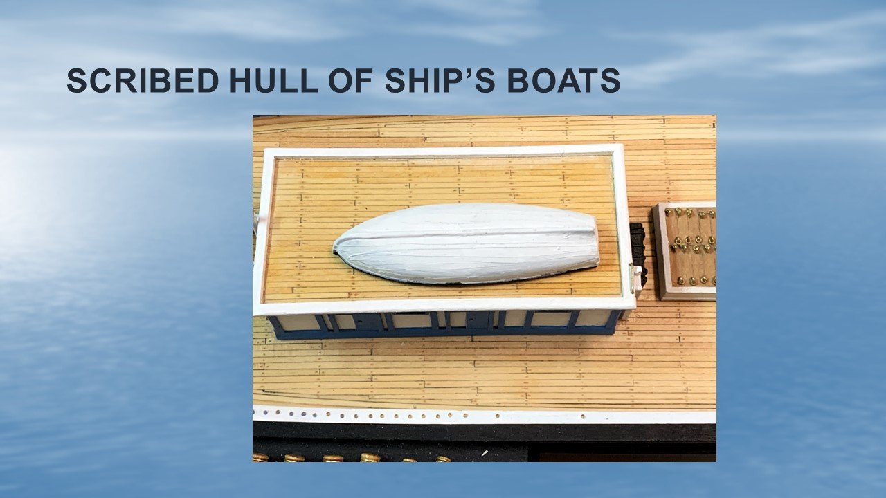
After my not so successful attempt at using vacuum forming to make my ship's boats, I spent a lot of thought on how I could make the hull appearance of the Britannia boat castings look more realistic, without adding to the thickness of the boats. I decided to try using an Exacto knife to scribe shallow line on the outside hull surface, to try to create the appearance of a planked hull. Here is my first go. I used a proportional divider (with some difficulty) to lay out the plank lines. The actual scoring of the metal with the knife requires a very steady hand, which I hope to improve upon in my subsequent attempts.
- 431 replies
-
- 2
-
-
- Flying Fish
- Model Shipways
- (and 2 more)
-
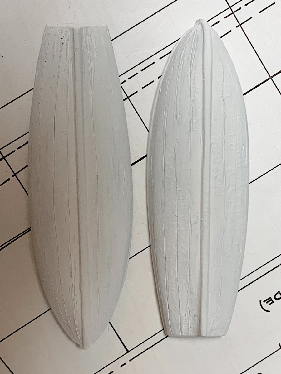
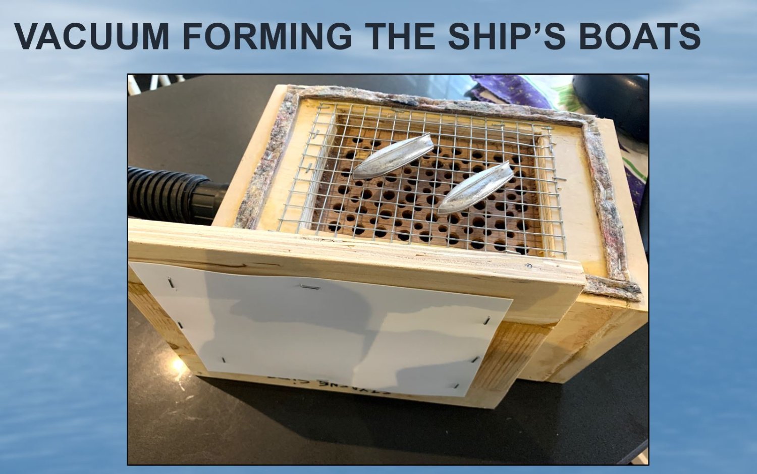
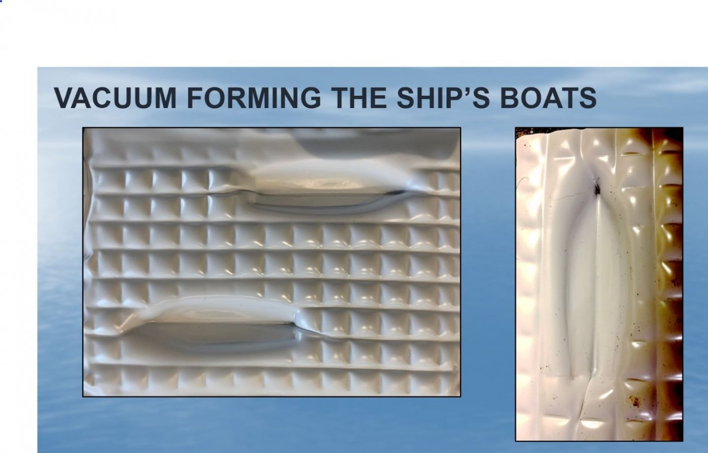
Following up on the suggestion by Roger Pellett, I had a go at trying to use the vacuum forming technique he described in the tips section of this website to make my the ship's boats in place of the thick metal Britannia boat castings supplied in the kit. FIGURE 1 below shows the setup I built. I used the Britannia castings as the basis for the mold. I stapled individual sheets styrene (Evergreen Scale Models; 0.02 and 0.015" thicknesses) onto my wooden frame (Fig. 1) and heated them at 350 F for 3-3.5 min in a small oven at which time the plastic was sagging in the frame. I quickly removed the frame from the oven and placed it on my vaccum box under suction created with a shop vac.. In each case, the softened plastic quickly pulled down onto the Britannia molds and solidified. My results I obtained with the 0.015" sheet is shown in FIGURE 2. I encountered two problems: 1) In some spots the plastic did not pull down evenly over the mold, leaving folds. You can see this in Fig. 2 at the ends of the boats. The problem was worse with the forms I made with the thicker plastic; as 2) the plastic did not pull down well enough at the level of the frame. I suspect that more vacuum may be necessary to overcome these problems. So whole I enjoyed this learning experiment, I probably will be using the Britannia castings supplied, which I will try to enhance in other ways.

- 431 replies
-
- 2
-
-
- Flying Fish
- Model Shipways
- (and 2 more)
-
That's what I found. I have some photos of my drilled taffrail on page 1 of my build.
- 602 replies
-
- 1
-
-
- Flying Fish
- Model Shipways
- (and 2 more)