

moreplovac
-
Posts
792 -
Joined
-
Last visited
Content Type
Profiles
Forums
Gallery
Events
Posts posted by moreplovac
-
-
A little bit of a filling is required to make sure all edge lines are as smooth as possible. Here is a need that gap between veneer and wood is filled with a putty and sanded..

Completed. I use wood putty, Elmer's brand but any will do the trick.

A bit of the same corrective surgery is needed around windows as well..

The wale veneer has a bit of a light black shade and it is different than the shade of the rest of black veneer so i decided to paint them in flat black.. Still researching for a decent airbrush-compressor combo (would appreciate feedback from you guys about suggested and good airbrush combo), the painting is done by hand..
There are few spots to correct after but overall satisfied with result. The cap rails were also painted in the same colour.
Happy modelling.
- dkuehn, Edwardkenway and Dutchman
-
 3
3
-
Continue with work on the hull

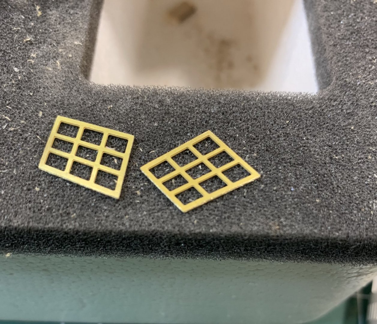
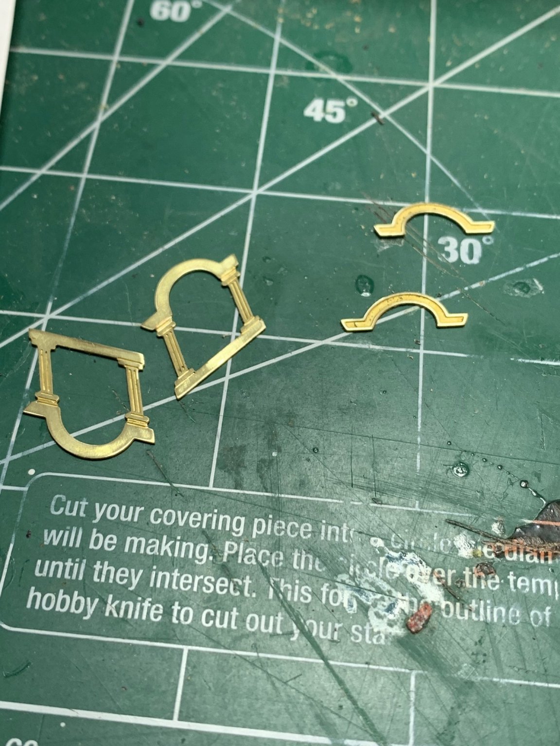
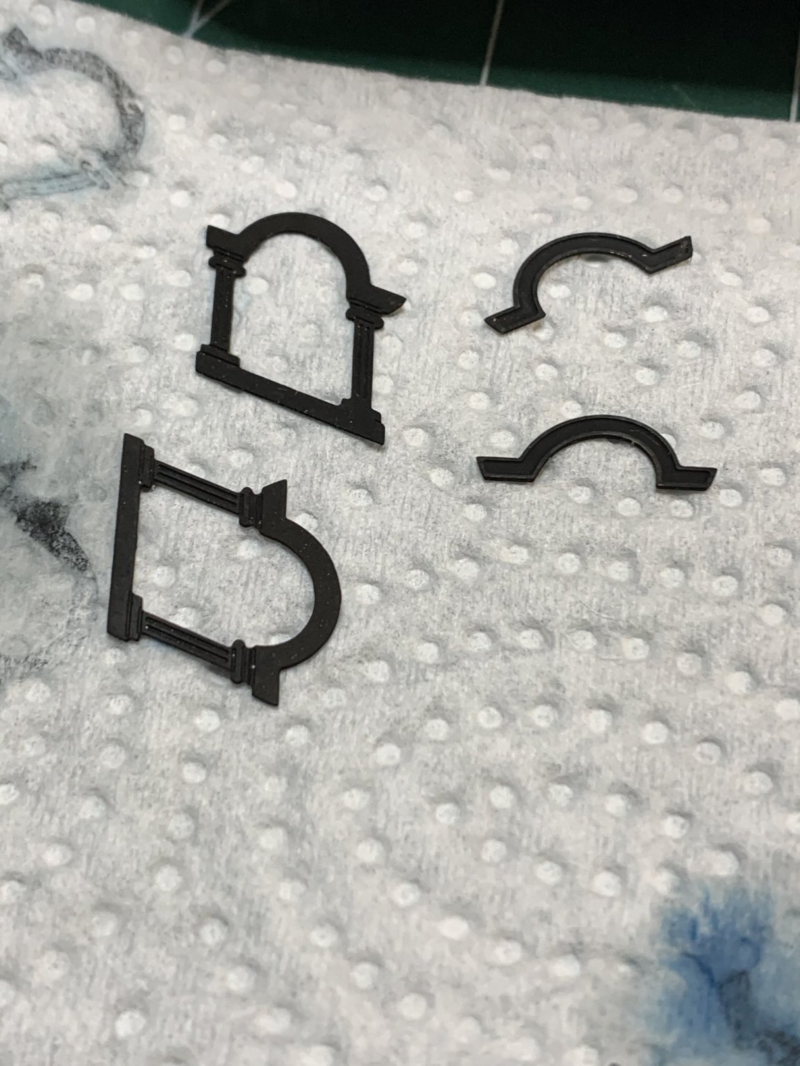
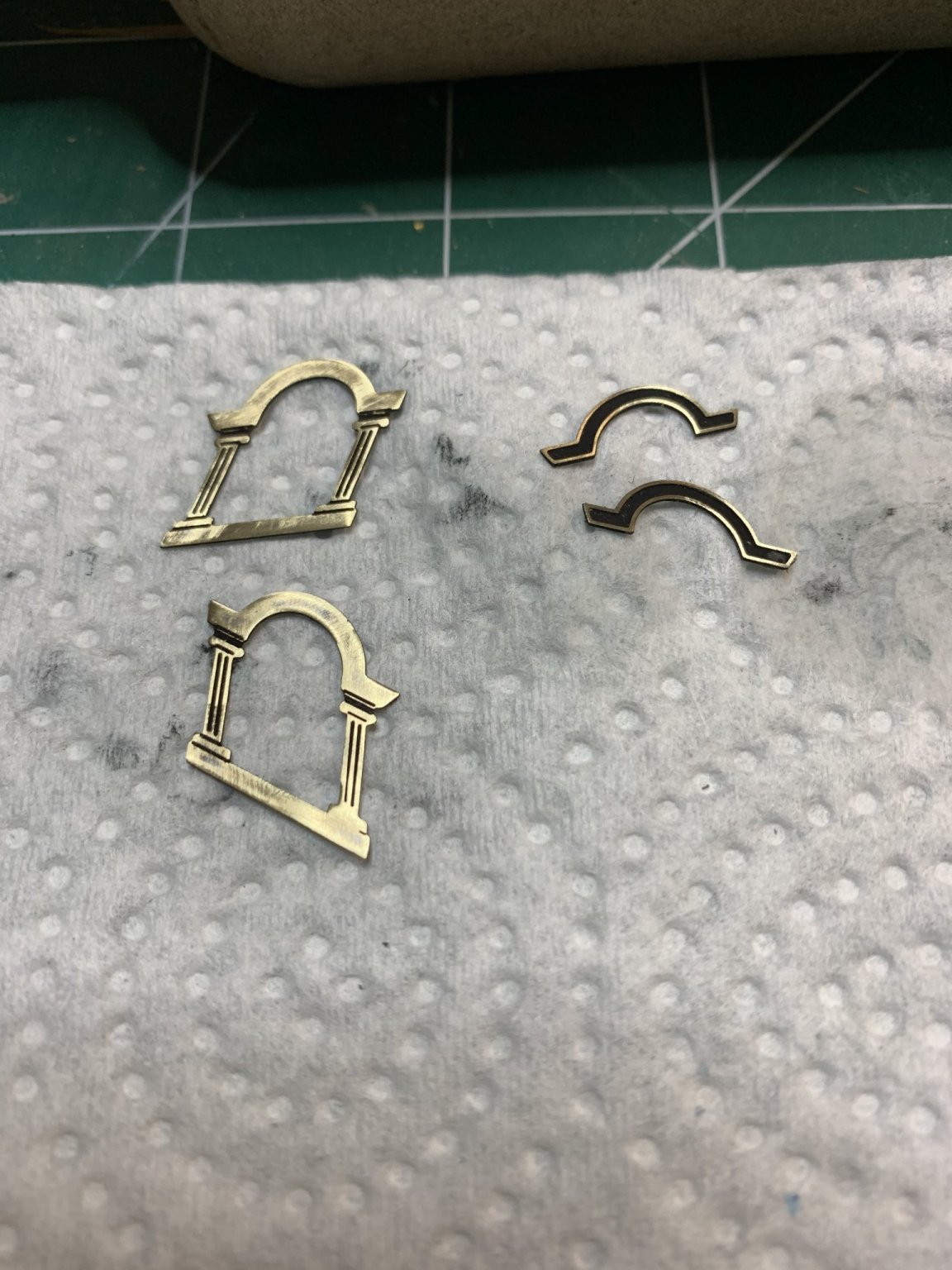
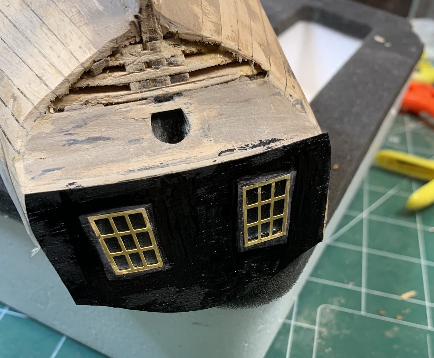
Blackening of the window decoration is next. Cut, sanded, and a quick bath in blackening solution..
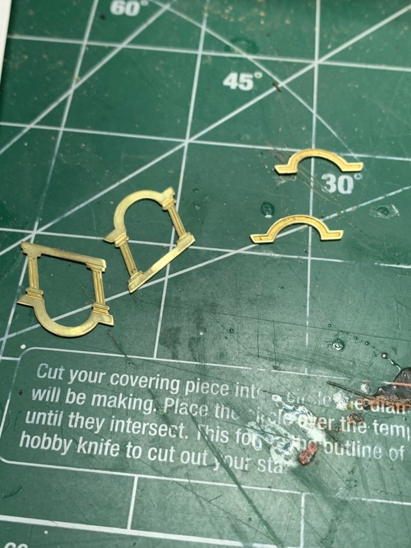
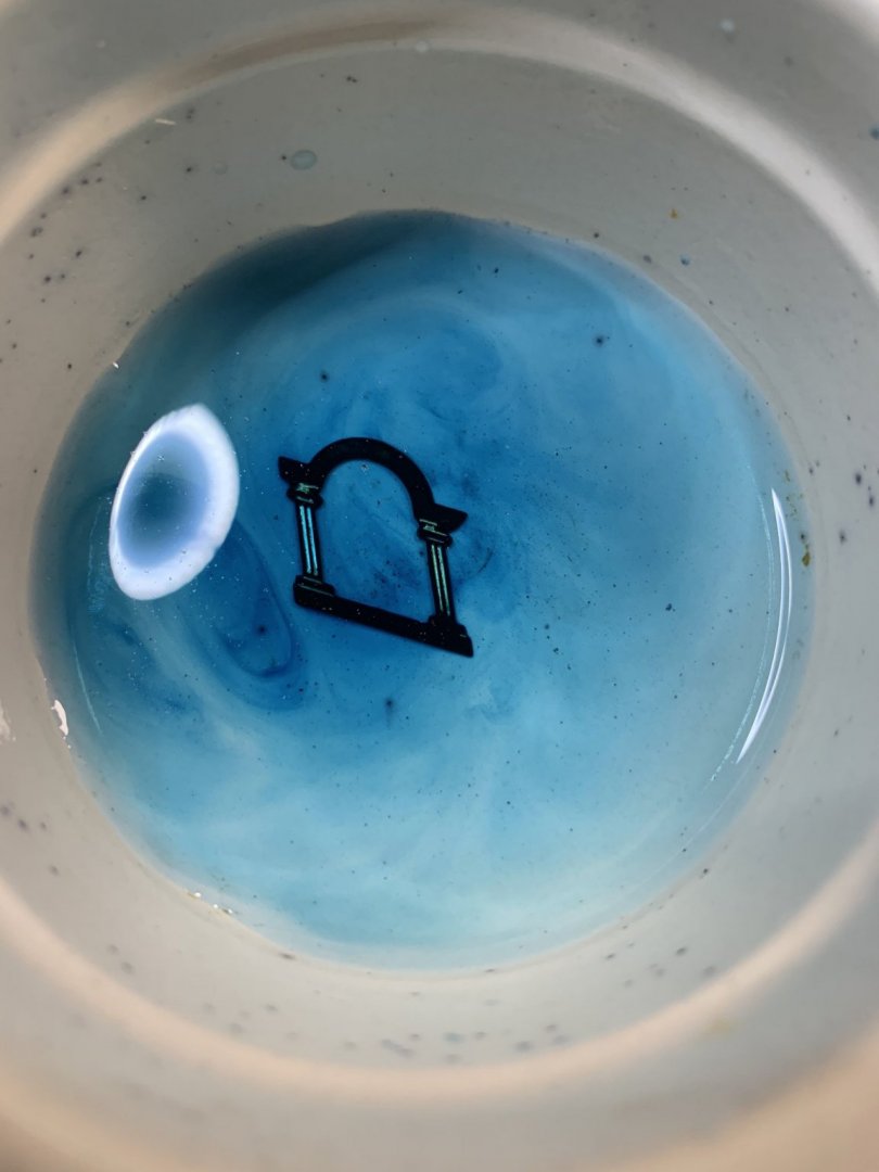

The blackened parts were sanded lightly..

Mounted around windows.

Then more decorating...
I am protecting window and frames with a piece of bounty and a transparent tape. Then i thought about it and replaced scotch tape with painter's yellow tape for delicate surfaces. It looks that scotch tape can pull up veneer parts..
At this moment not quite happy with veneer in layers, mixed feelings....

Managed to get it done, the cap rails are completed.

If this work from home due to Covid continues i am going to finish this build fairly quickly.
Happy modelling...
- Dutchman, Edwardkenway, dkuehn and 1 other
-
4
-
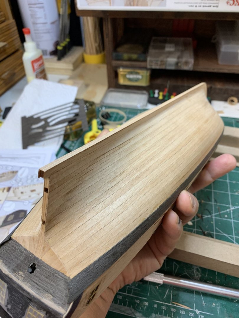
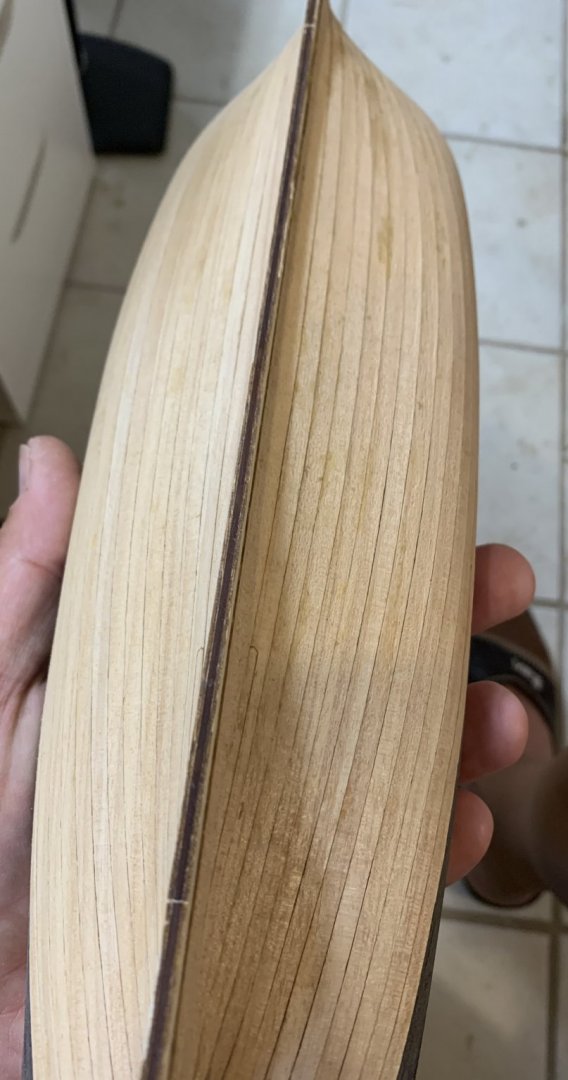
I bit of a keel work.... covering with veneer, sand, glue....

Happy modelling.
- dkuehn, Dutchman, Edwardkenway and 2 others
-
5
-
-
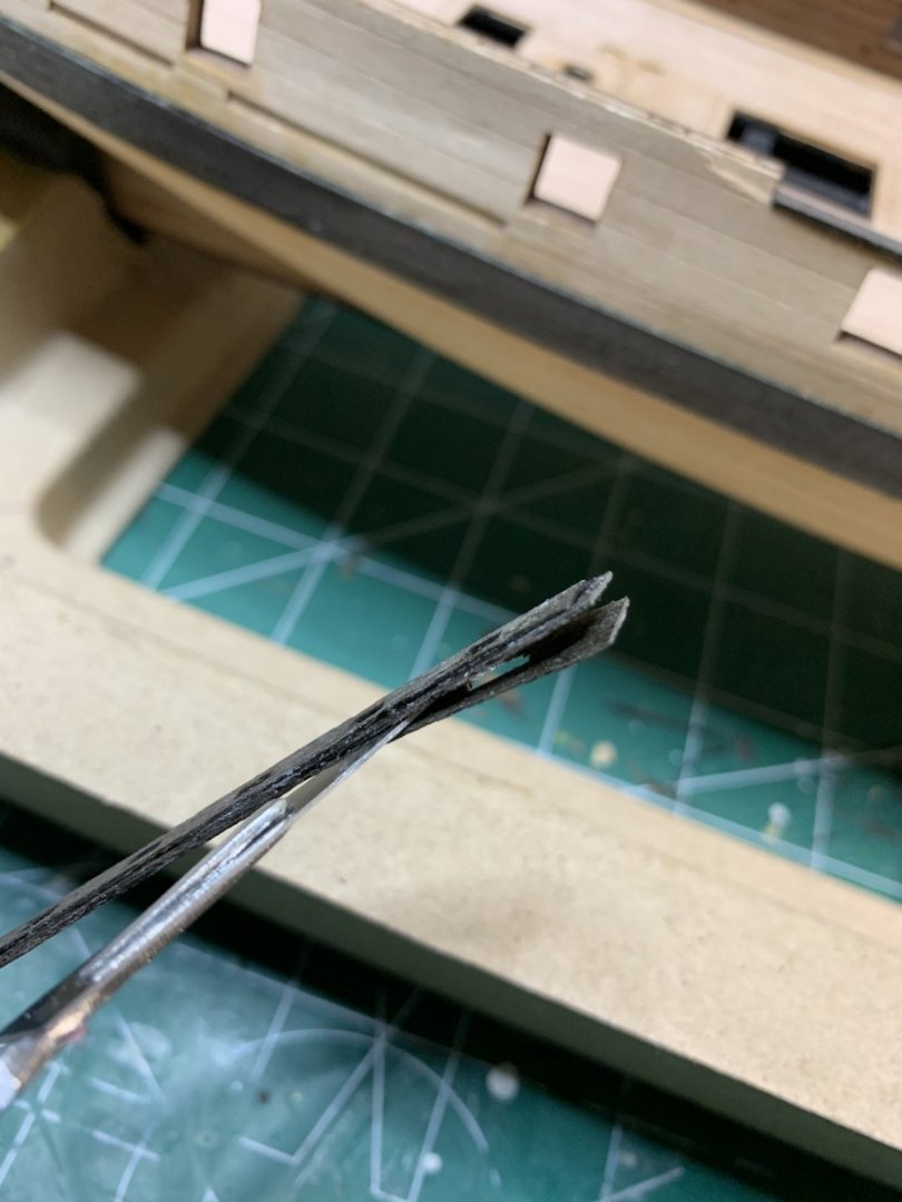
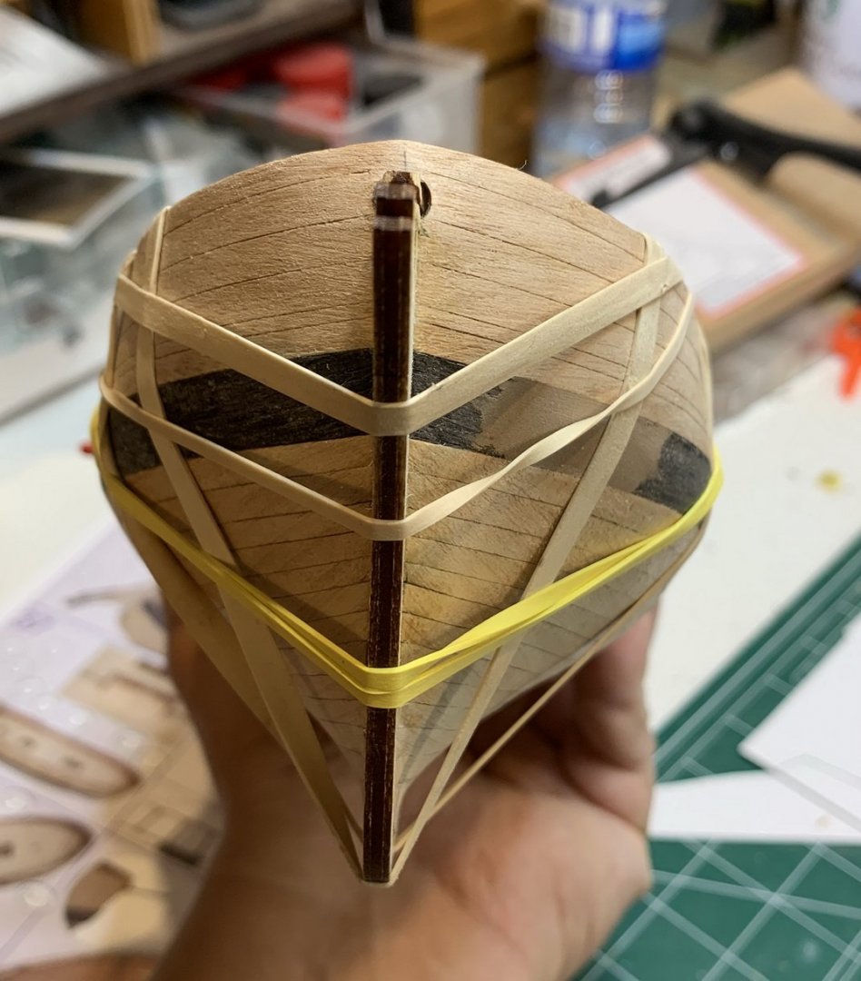
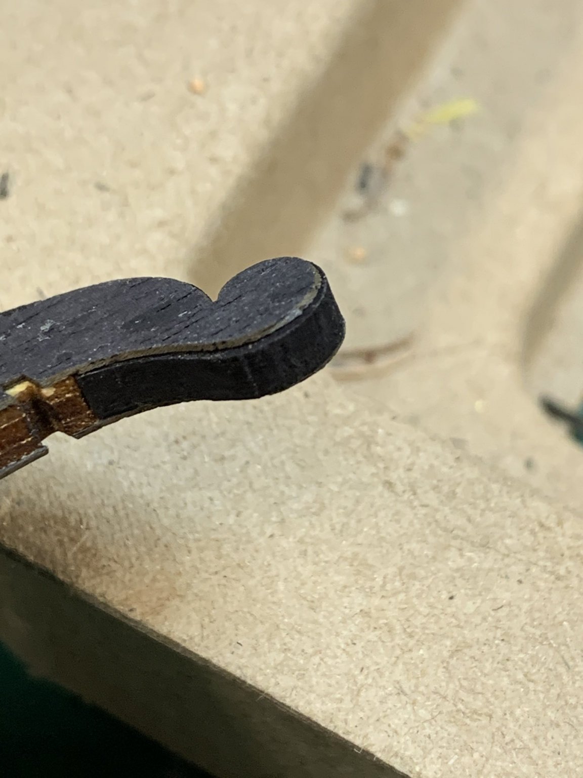
During the process of removing cap rails from the frame, i accidentally broke one.... and realized that thickness of them was made by gluing two layers of veneers together...

In all these, a good news was that only one layer was broken so i carefully removed remittance of the broken layer which gives me a an option to glue a good layer to another piece of the veneer of the same size (two layers) ending up with cap rail in three layers thickness.

After gluing there was just a mater of removing one extra veneer layer which was done with assistance of few drops of acetone..
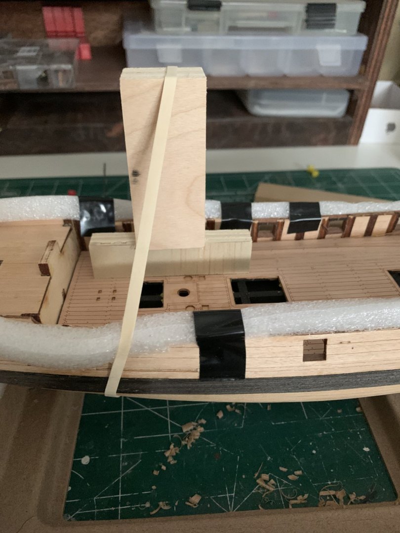
Then cap rails were glued in the position and fixed with rubber bands..
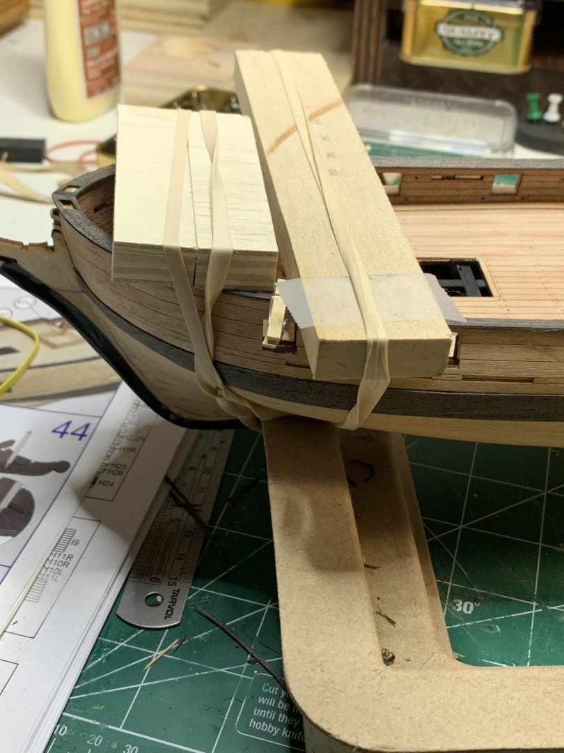
The rest of the cap rails on main deck were installed...

Sanding of all cap rails will be next...
Happy modelling..
-
Thanks, will do that.
Cheers
-
2 hours ago, DPK said:
Looks like you made some mistake: the toptimbers on the quarterdeck should be cut our, as I remember. Otherwise you will have wrong qurterdeck bulwark thickness and the gunwale will be too narrow.
Thanks, i will go thru instruction pages to check...
-
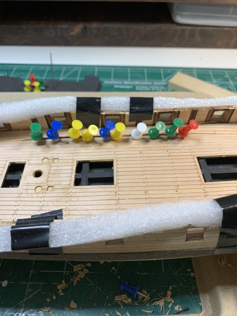
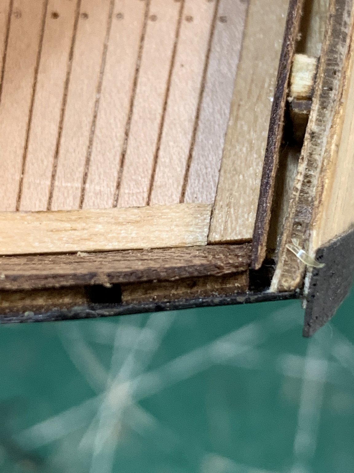
Now the waterways have to be adjusted to fit new stanchion size, no problem there...

Continue with waterways on stern... For some reason one waterway plank is not fitting correctly on one side...
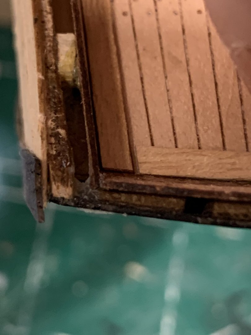
The other side is fine...

So, little bit of surgery will be needed. The new part was made out of the spare wood laying around. There are plenty of left over wood which can be used for various replacement tasks. Really like that 'feature'. It will be very difficult to find correct veneer size/shape if all parts are cut very tight to save some cost, like with some other manufacturers...
Traced, cut, shaped, glued...
and installed... All good.

Then started to work on cap rails... one at a time. Some fitting is required but not a problem... Very pleased with a kit so far...
Happy modelling.
-
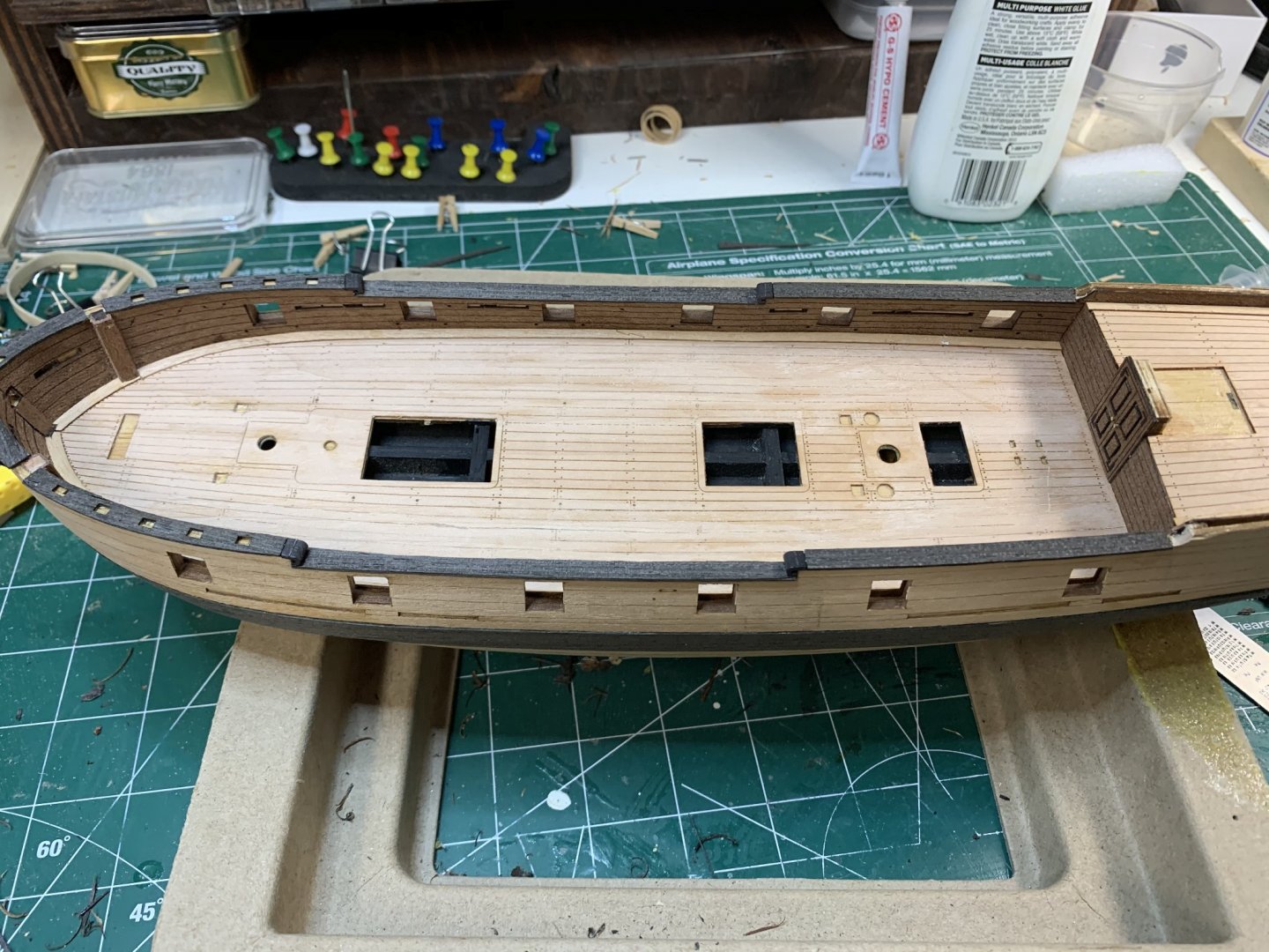
Continuing with planking and work on the deck installing waterways.. All fits perfectly.

Then i decided to cover stanchions in veneer that is left from other pieces.

For me the end result looks interesting..
Happy modelling.
- CiscoH, dkuehn, Edwardkenway and 2 others
-
5
-
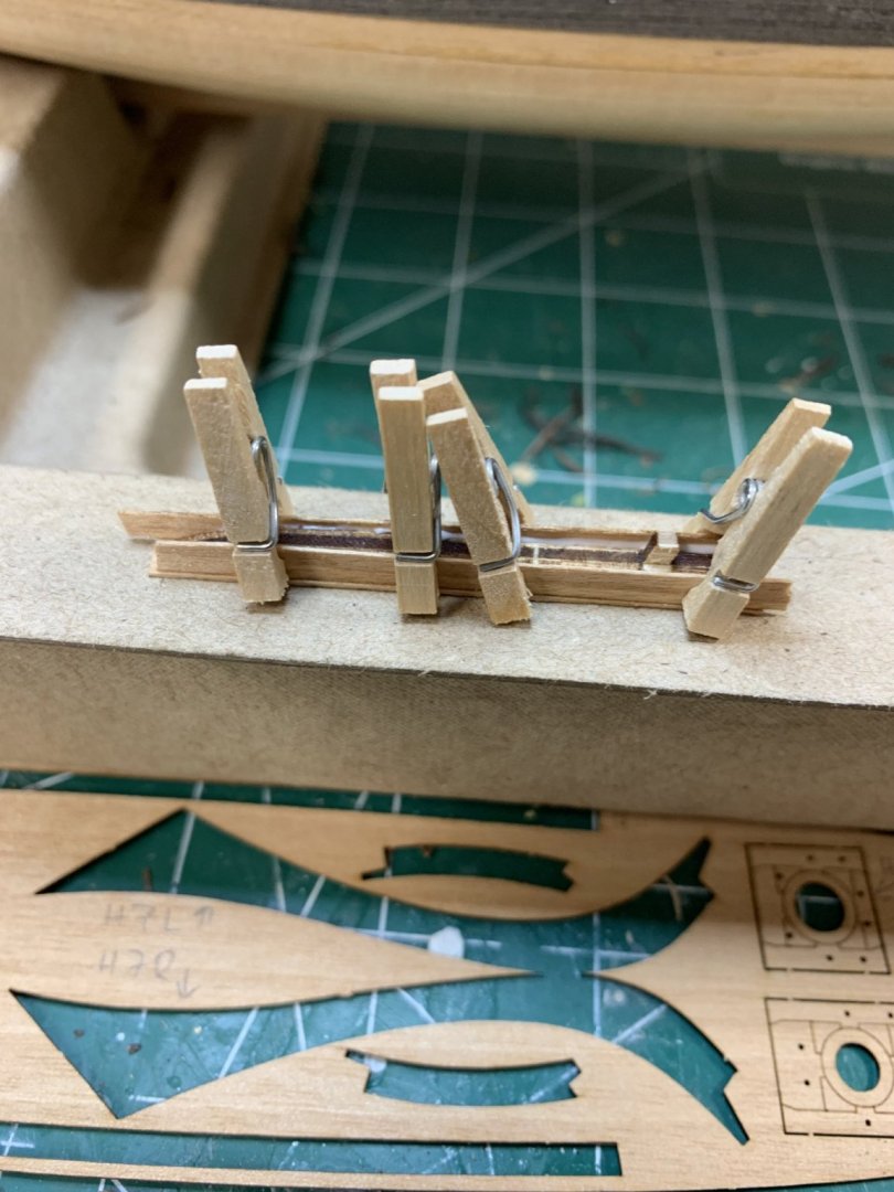
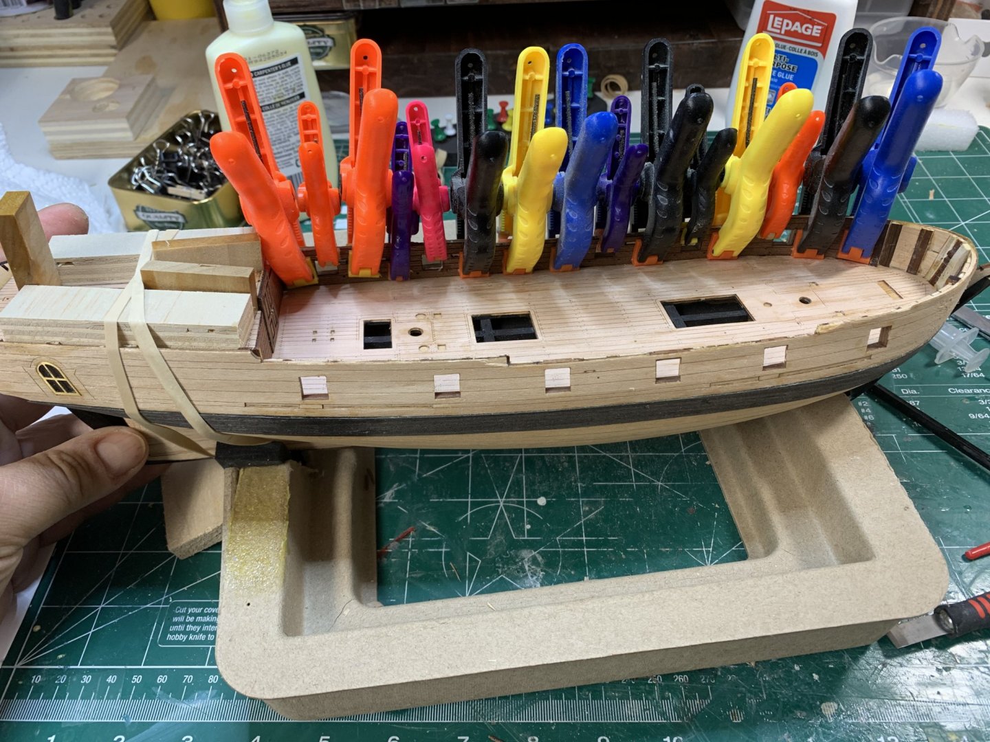
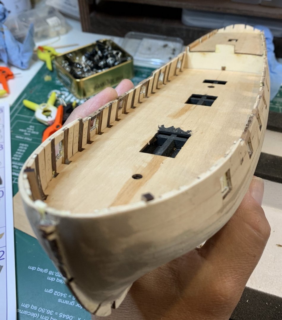
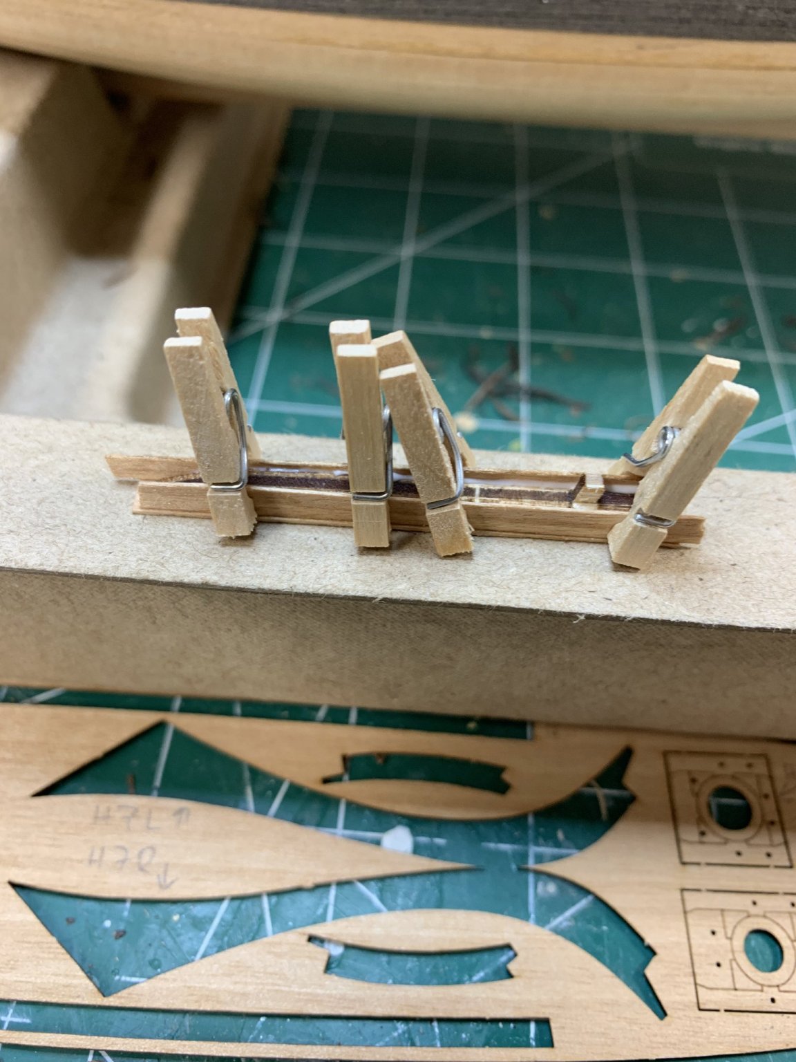
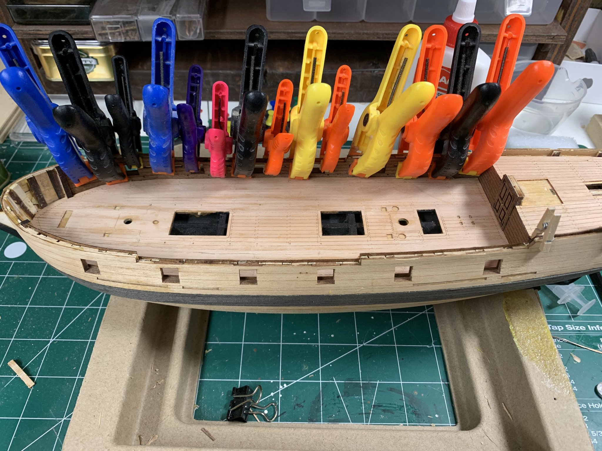
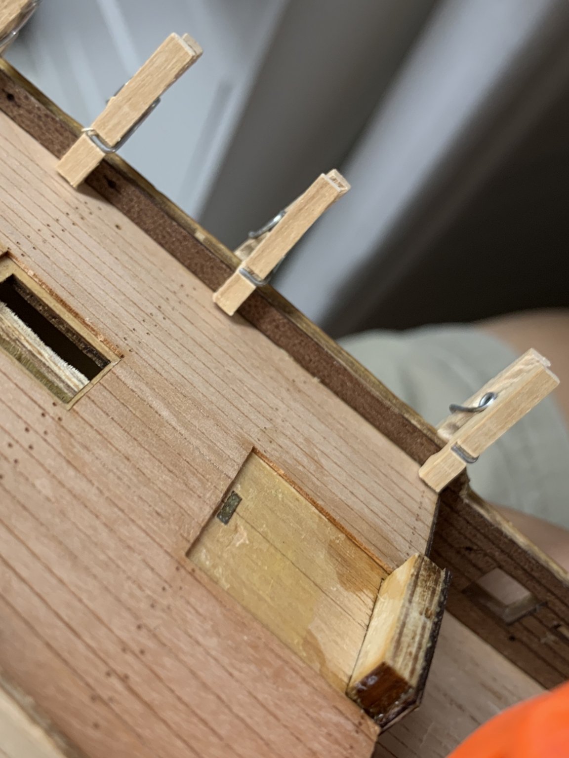
A bit of a work continues with inner bulwark planking, etc...

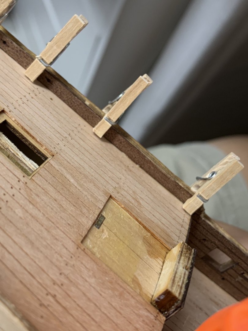
For this i had to adjust my tiny cloth pins so they can grab and hold parts correctly..
Happy modelling..
- Edwardkenway, JpR62, ccoyle and 1 other
-
4
-
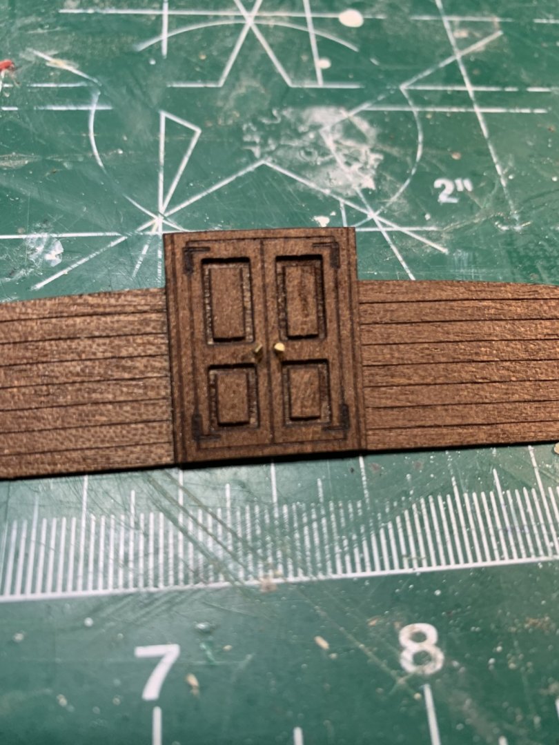
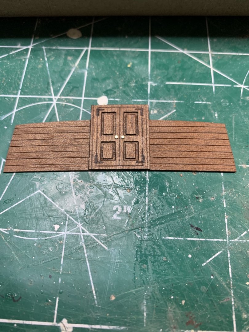
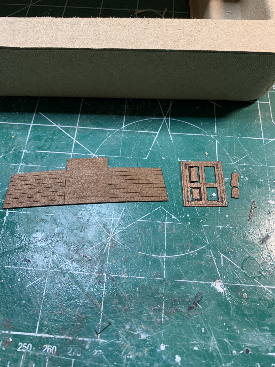
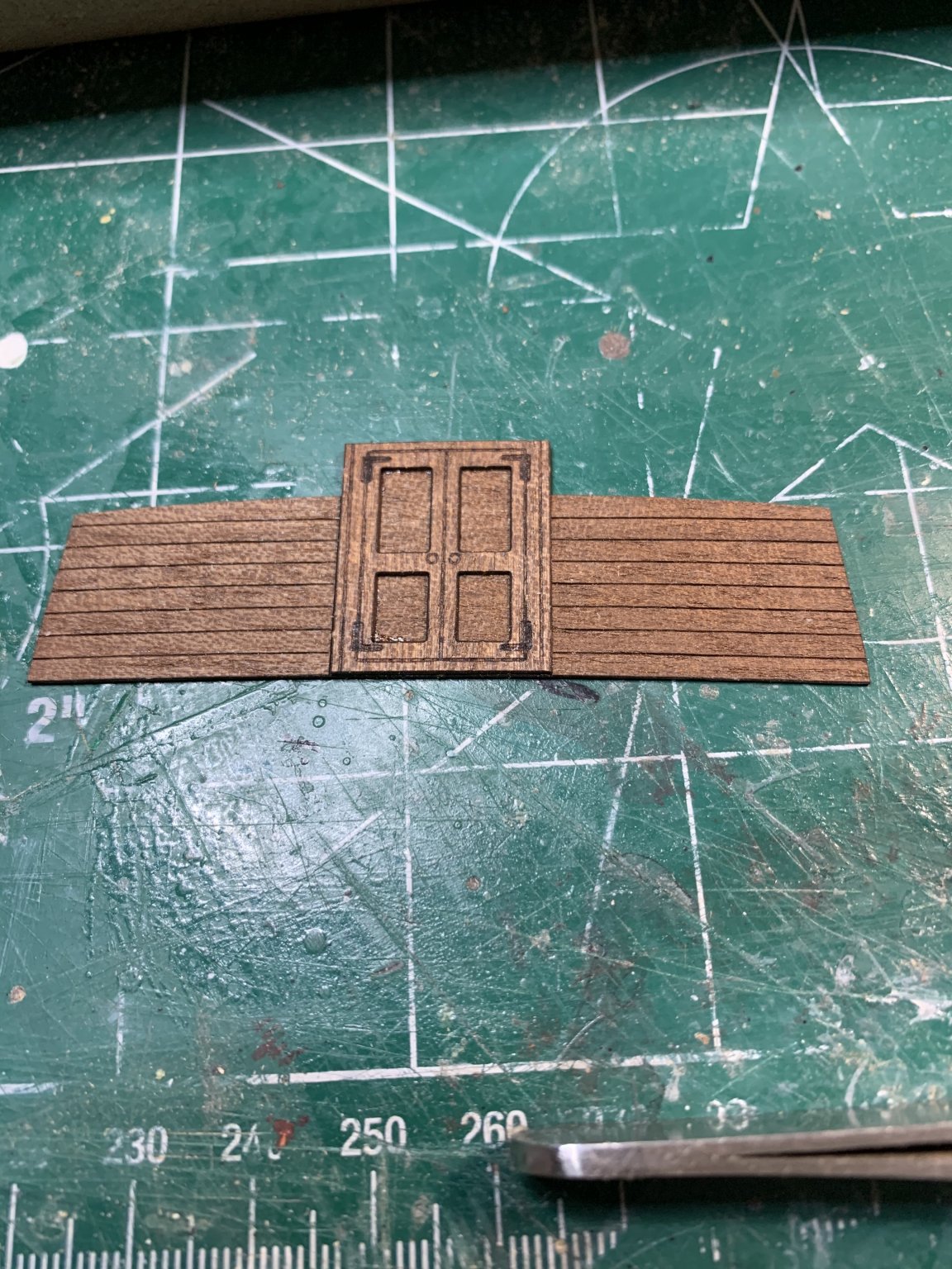
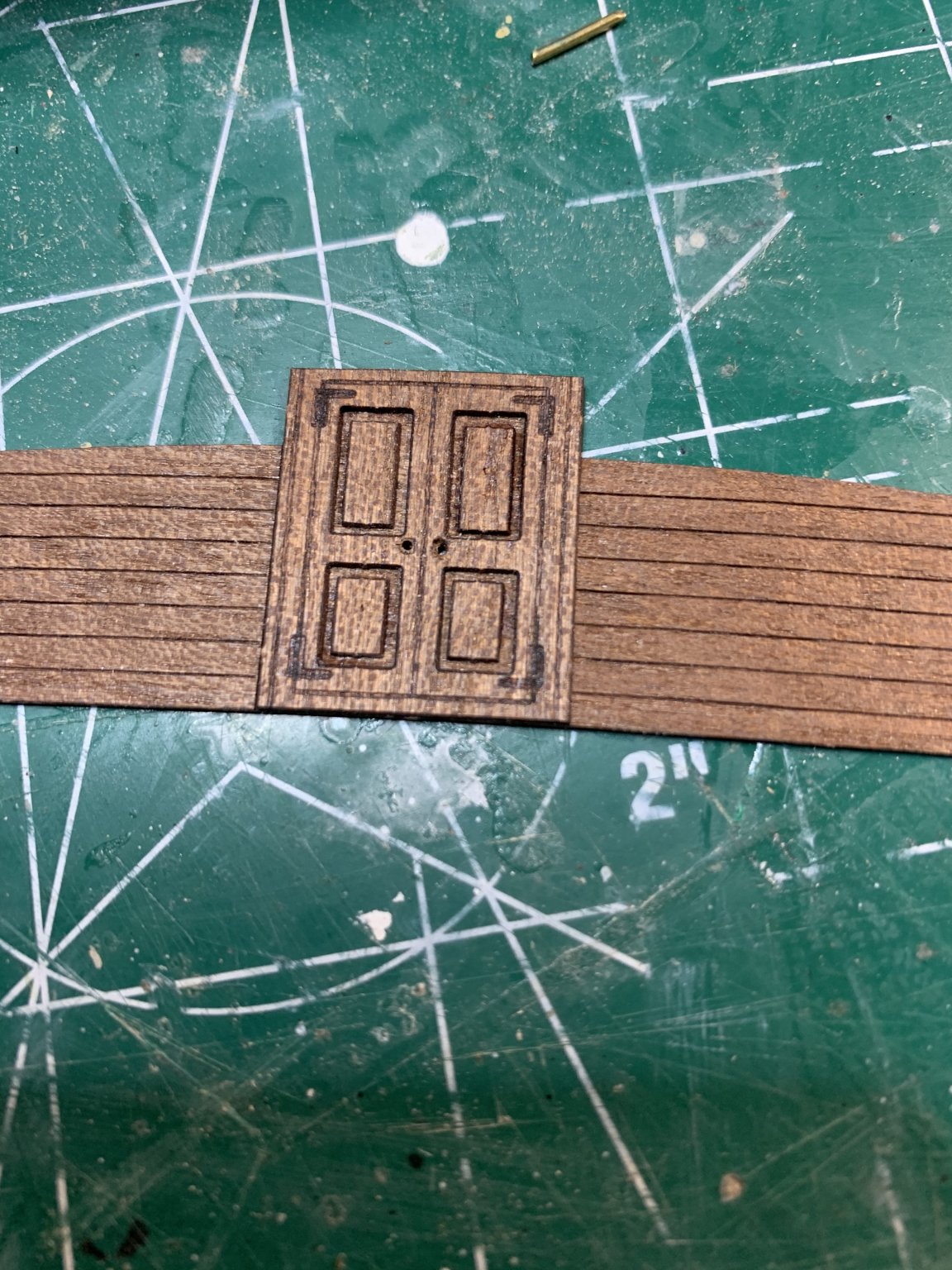
Work continues assembling doors... Cut, sand, glue....
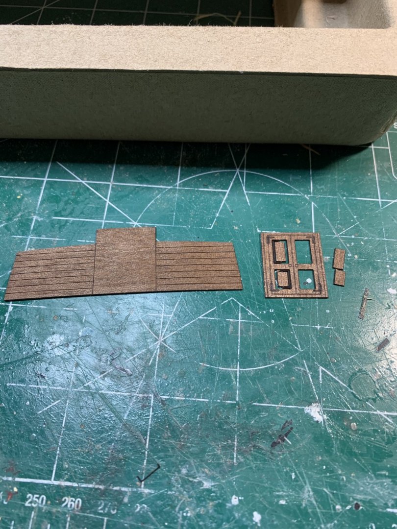


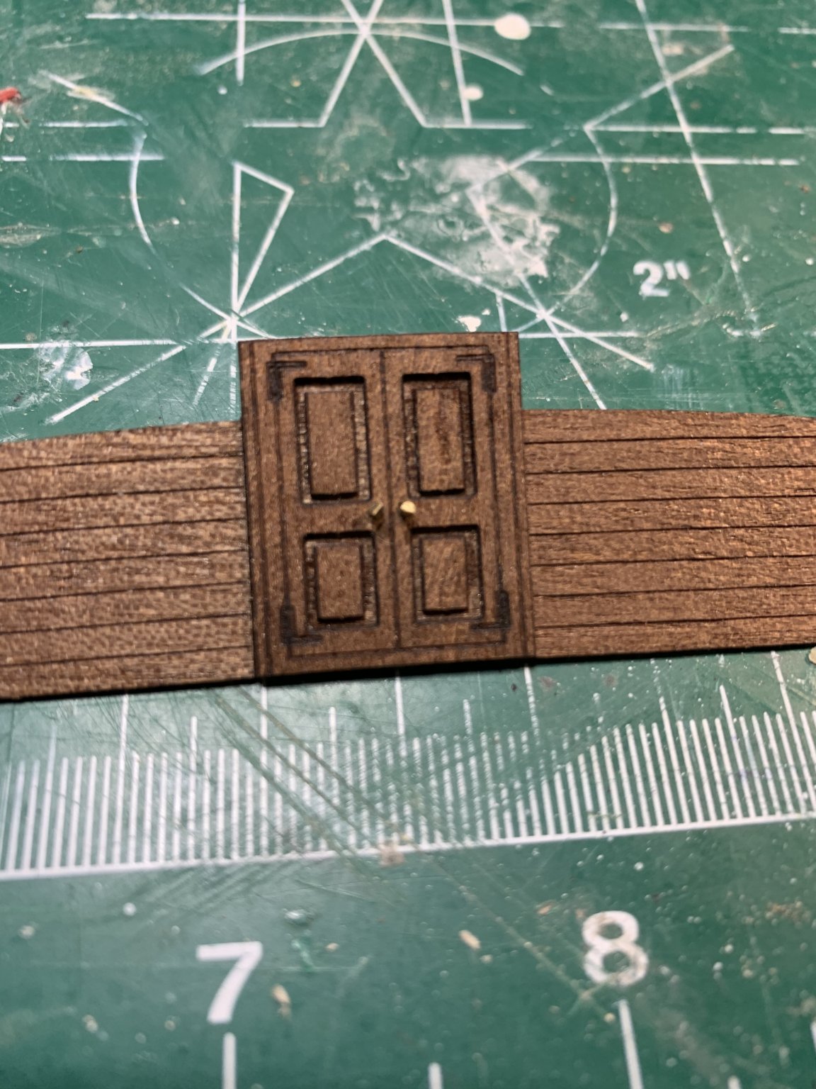
Holes were drilled thru and two pieces of wire inserted, cut and shaped to represent knobs...
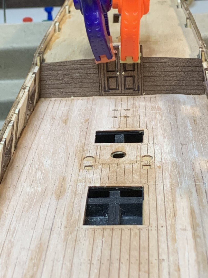
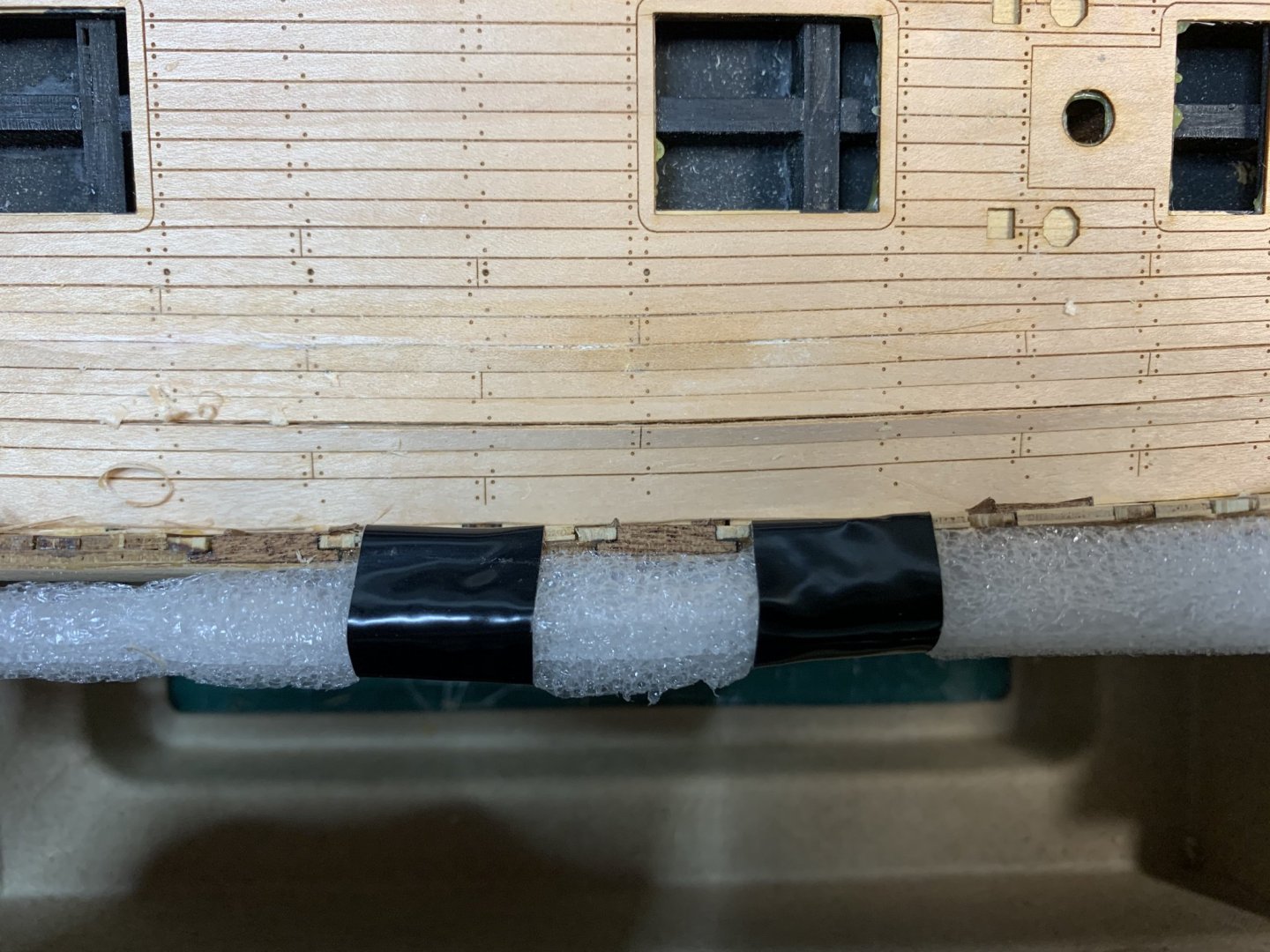
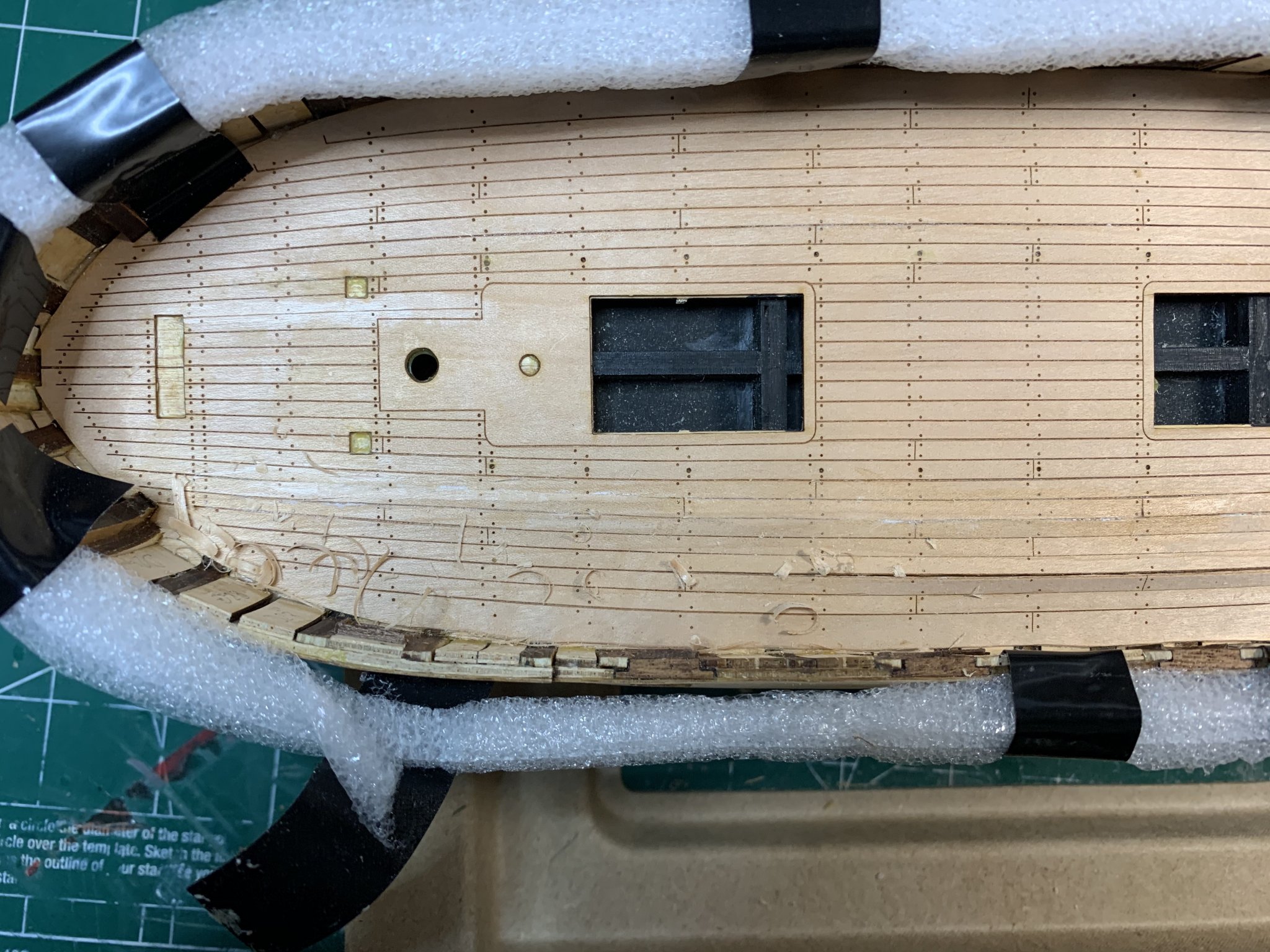
And planking on inner bulwark area was next.... test fitting few times, just in case ....
Happy modelling...- ccoyle, CiscoH and Edwardkenway
-
3
-
Shhhh, don't tell my boss, this work from home thingy is not that bad after all... I have setup my work (office) desk just on the opposite wall from my hobby desk and one chair is used for both desks. Now when i have some spare time, i just turn my chair around and voila...
A small corrective surgery had to be performed to correct the issue with the deck. This is one of the challenges i needed to fix. Was able to redo most of the affected deck areas by lifting it and gluing it back. For some i had to do combination of a different techniques to thin the wood and correct it. Very happy that deck itself is made from thicker wood so there are plenty of wood to work with...

Re-gluing was applied to certain parts and there were left to dry..

Starboard side completed; need to do a bit more sanding and to clean it up in prep for layer of protection...

Today will work on port side..
Happy modelling..- CiscoH and Edwardkenway
-
2
-
OK, so we are back... now i need to pick up where i left it some months ago...
The new stern was build tracing the original part and adding some extra millimetres that will be sanded down after. The process consisted of several short sanding stroke, measure, test, sanding again, measure, fit.... The part was glued and left overnight to completely dry.. Some shaping and sanding will be done next.
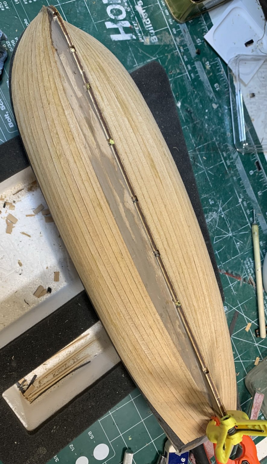
Then the last plank on the keel was installed...
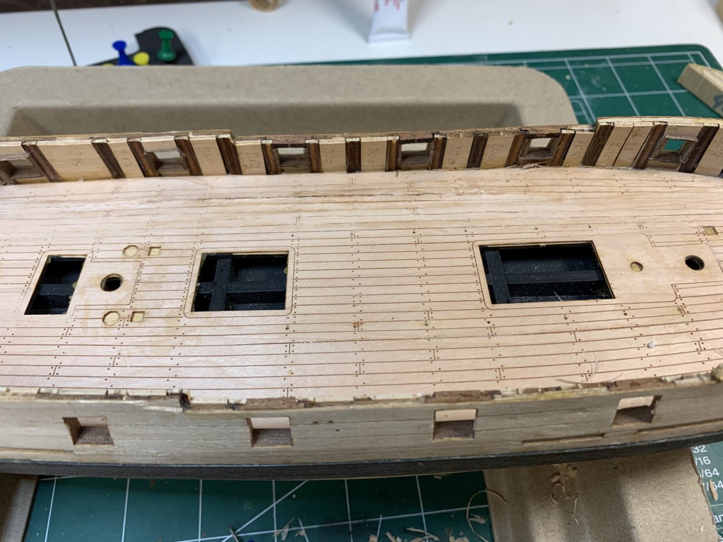
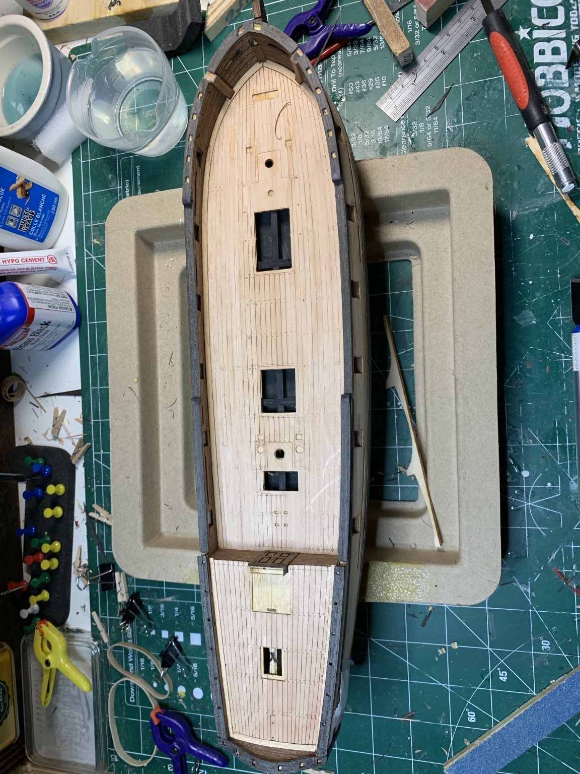
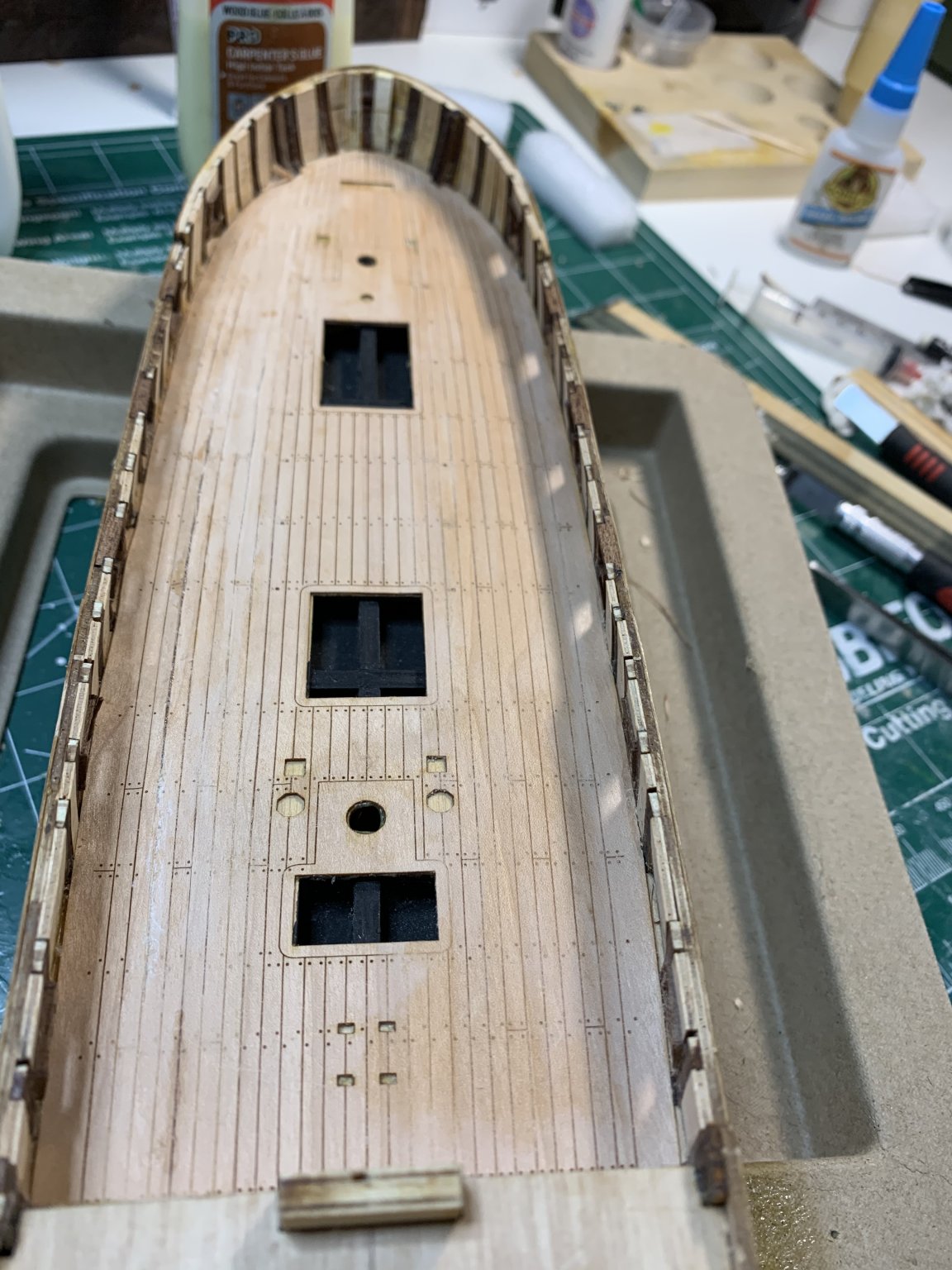
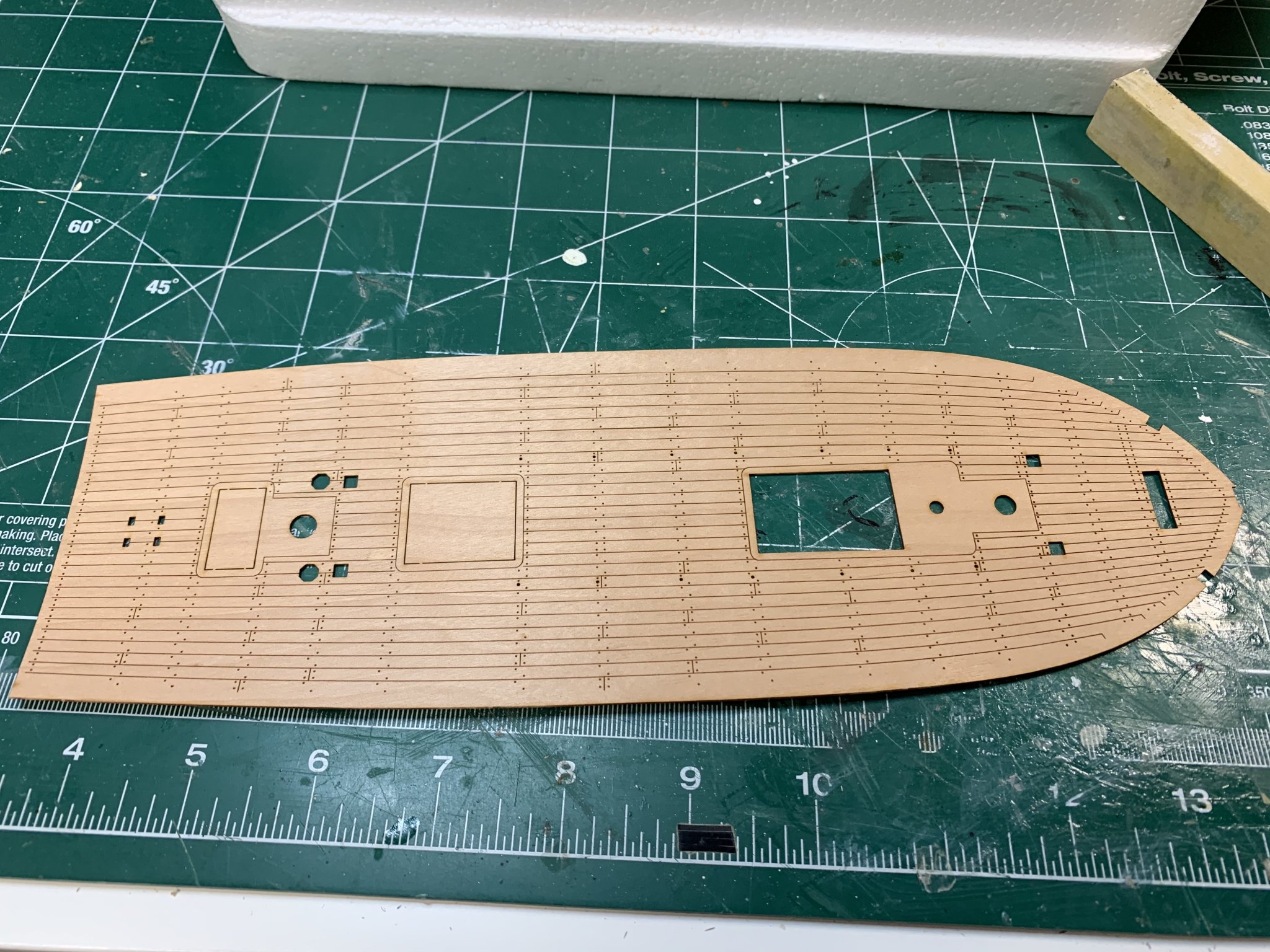
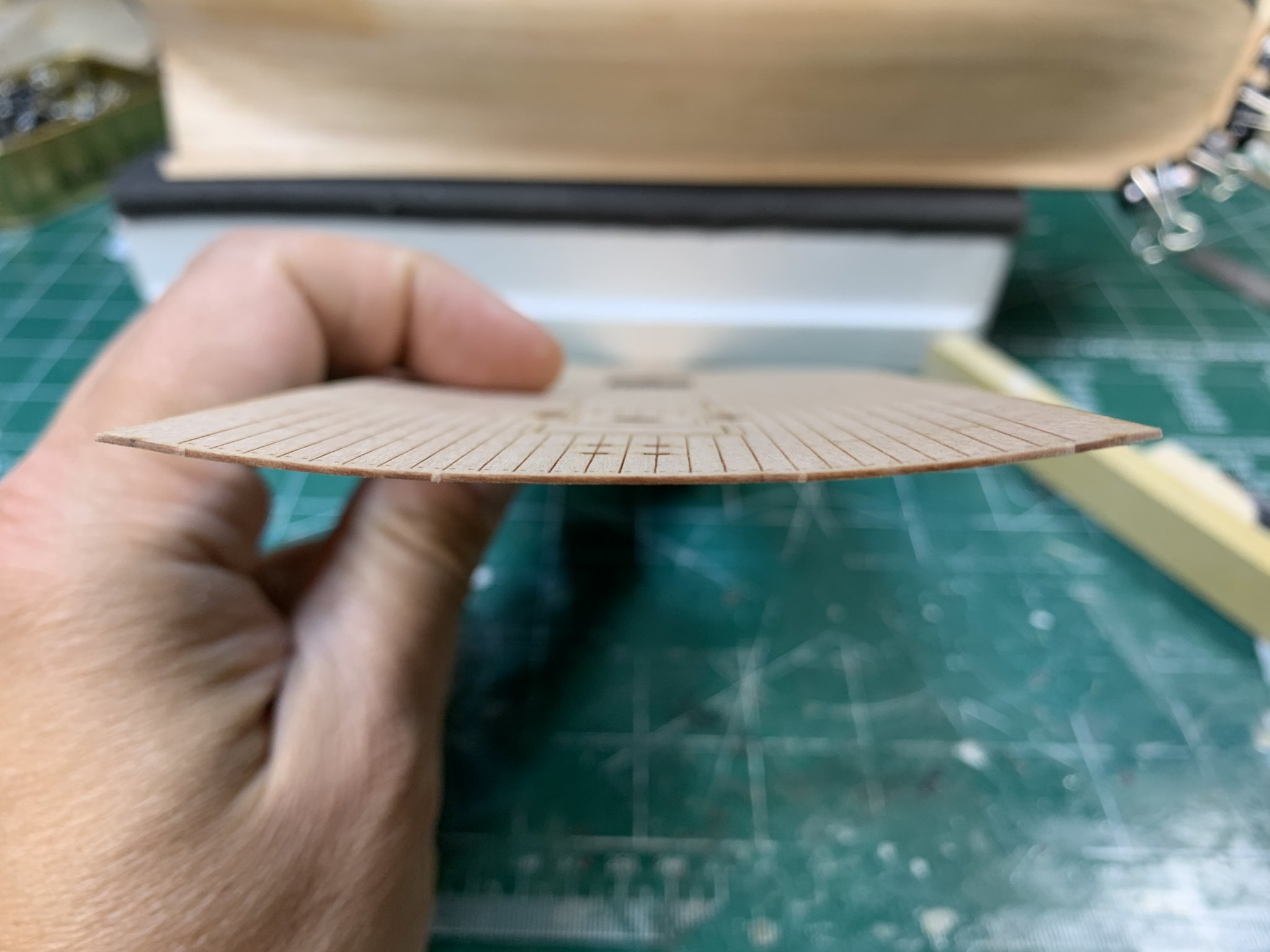
While these parts are drying i start working on the main deck. The main deck planking is done with laser cut part, out of one piece, very precise and neat.

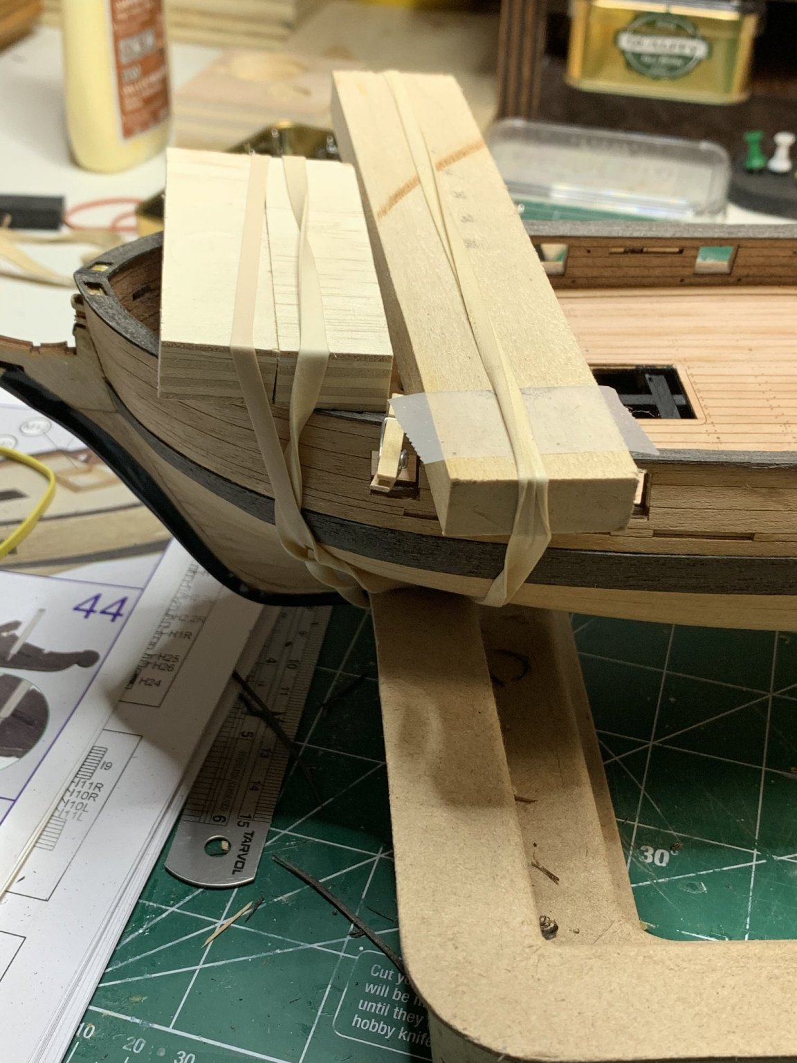
Not sure if because of some months in the open box, but the deck was getting out of shape (like myself with limited amount of outdoor activities due to corona)...

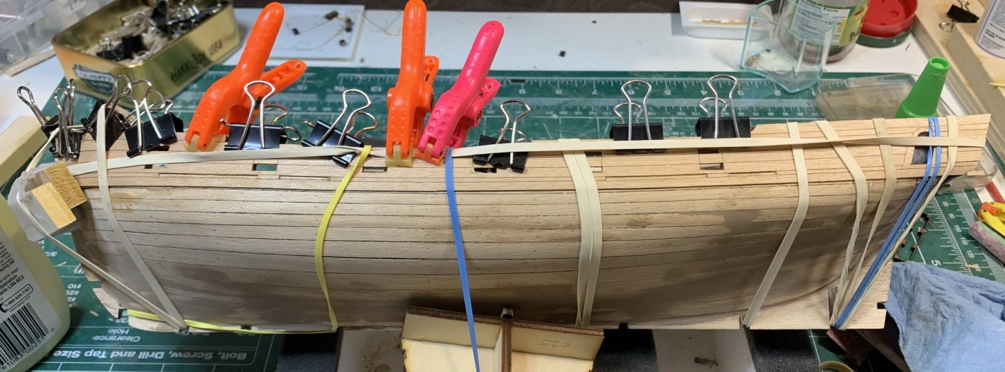
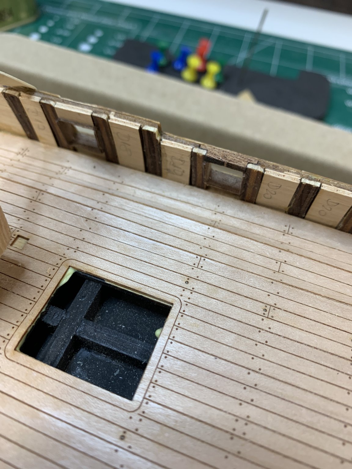
I tested with dry fitting and all was looking OK. Applied a glue on the whole deck and put so called false deck on the ship.. during fitting process some parts started to dry and deck starts to twist. Not sure if this is related to water in the glue or something else but the end results have some parts (where two planks are connected together) sticking out and creating kind of rotated V shape...

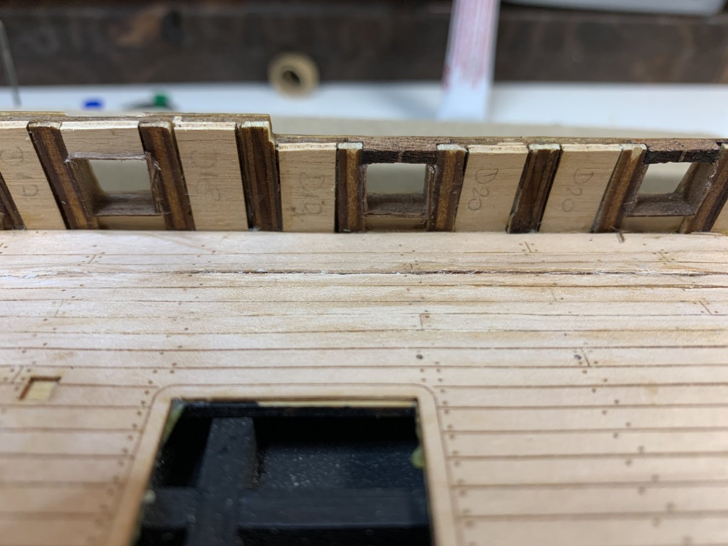
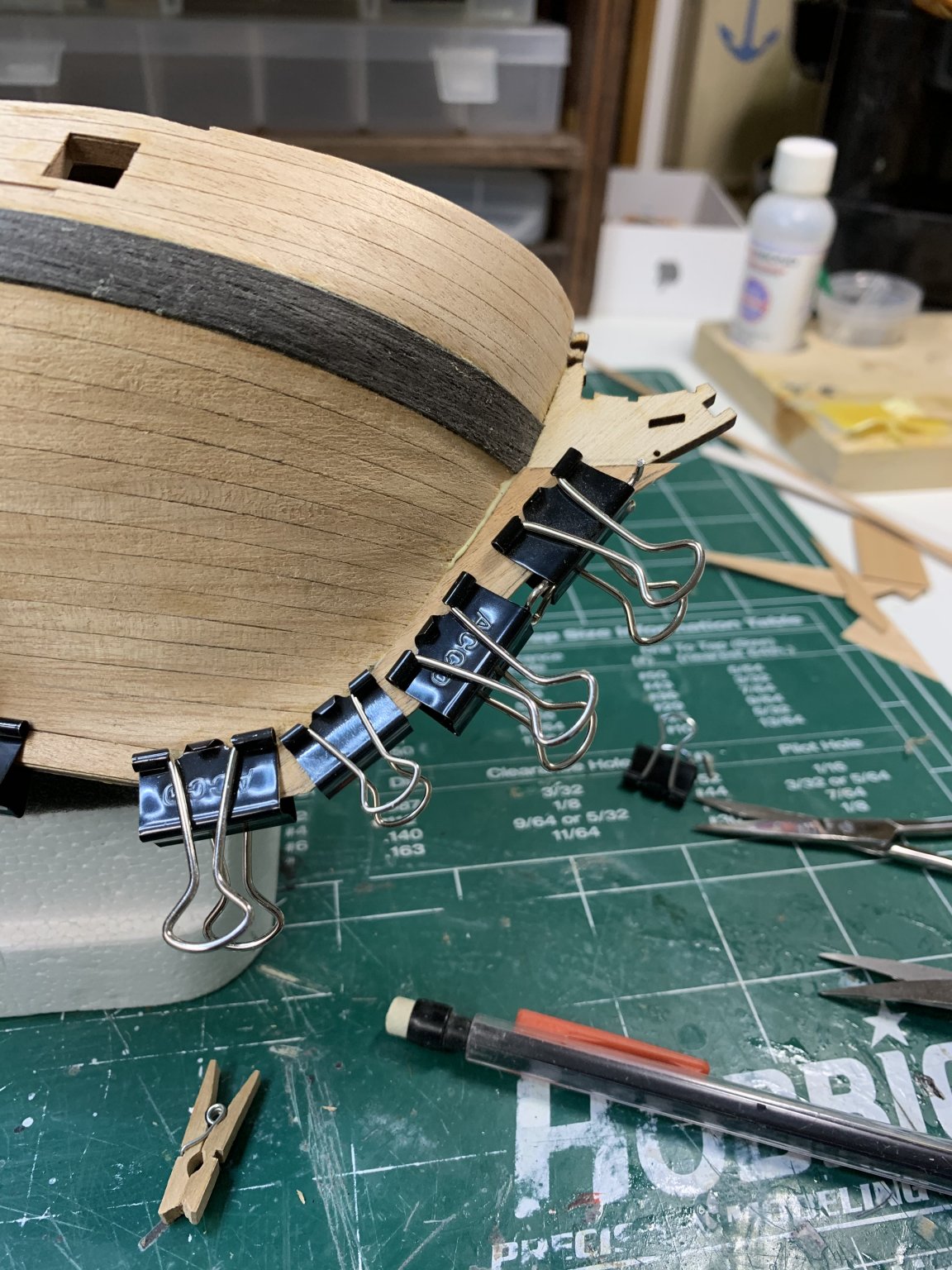
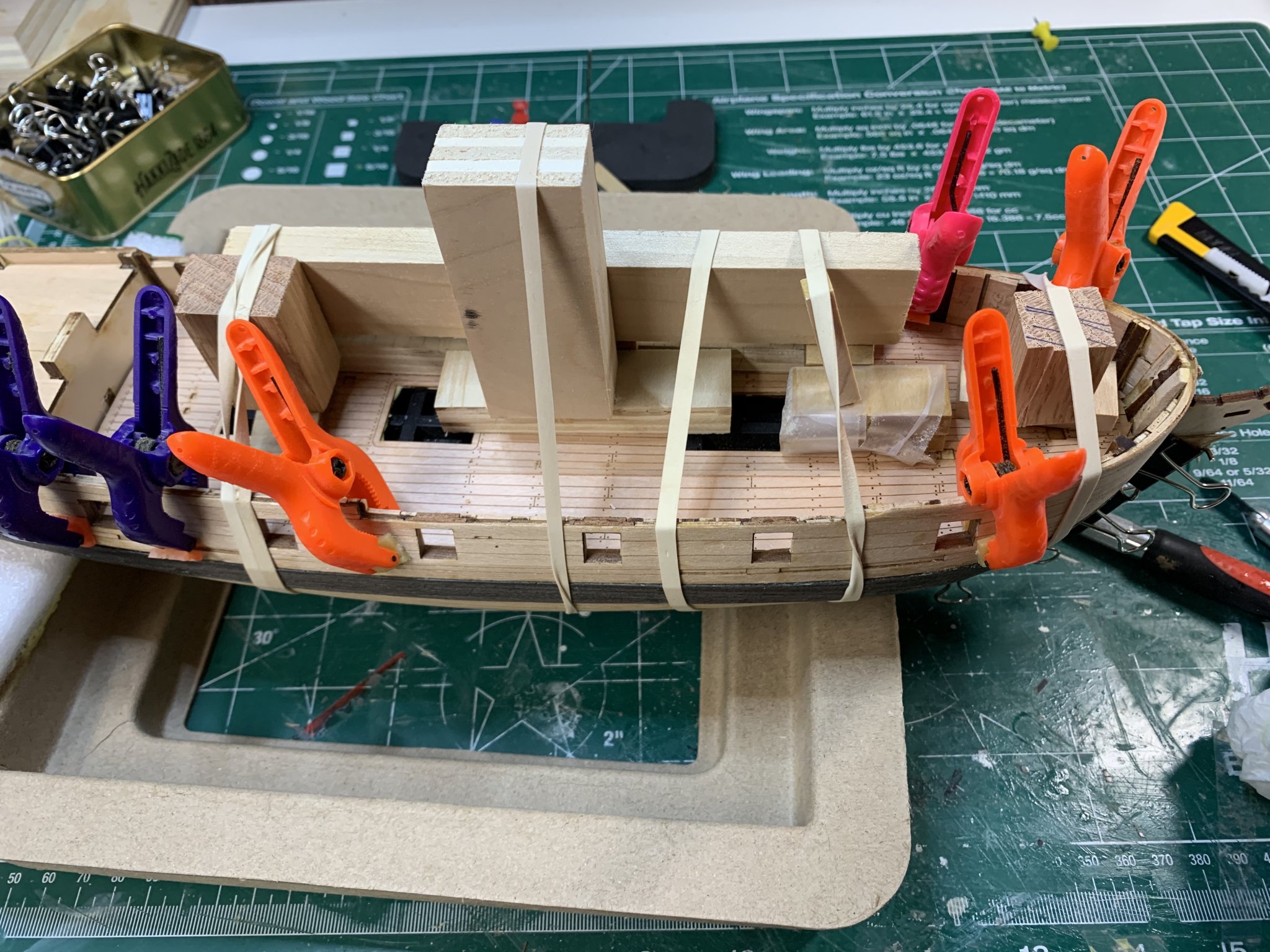
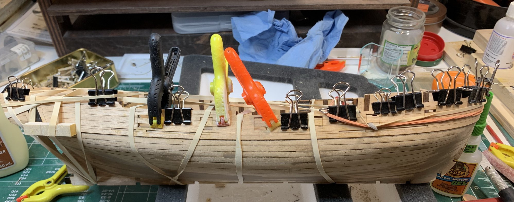
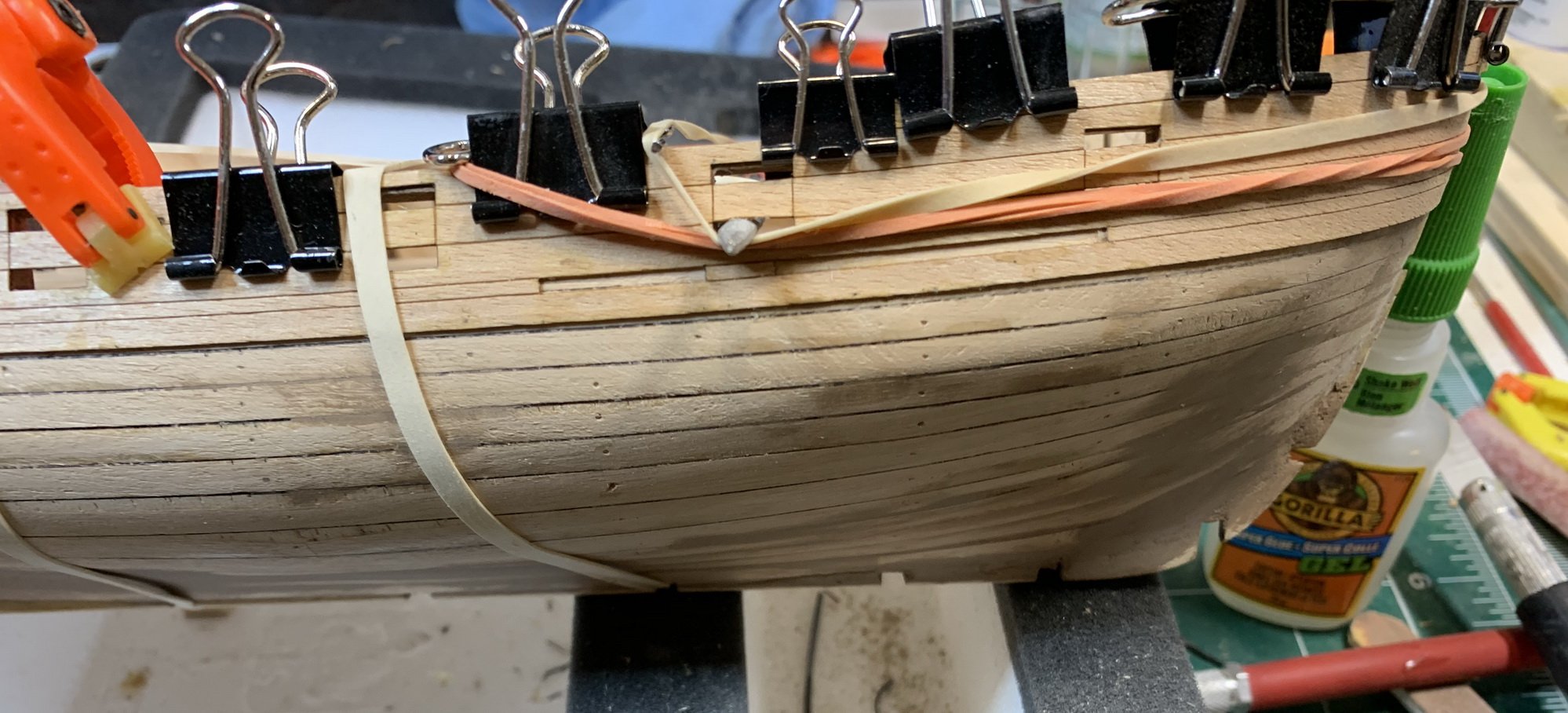
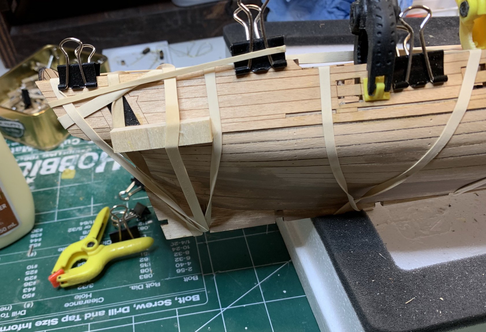
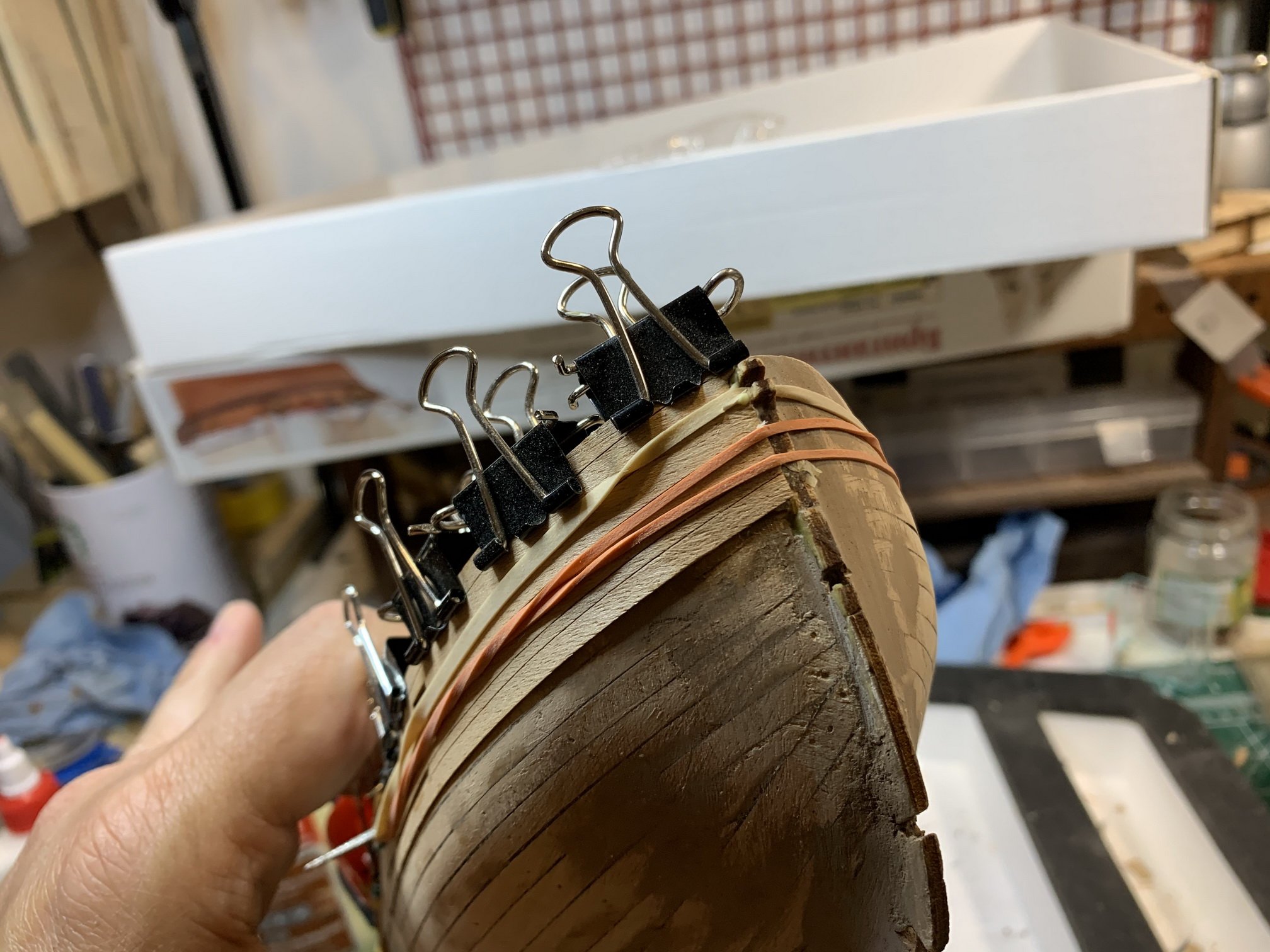
So tons of rubber and spare wood pieces are called in to assist pushing those areas down to the deck and help gluing them properly.

Then i realized in this case the bulwark edges can be in danger of getting chipped off so i removed rubber bands and put a layer of protection on the bulwark' edges.
Today i will continue working on the deck and correcting those "V" issues. Not sure what woudl be the correct procedure to avoid this type of thing; maybe mounting a deck before all bulwarks are in place to allow you to squize the whole deck with one big piece of wood, or some other way of installing it... We will see the results.
Happy modelling..
- JpR62, Edwardkenway, ccoyle and 2 others
-
5
-
-
A little bit of progress ...
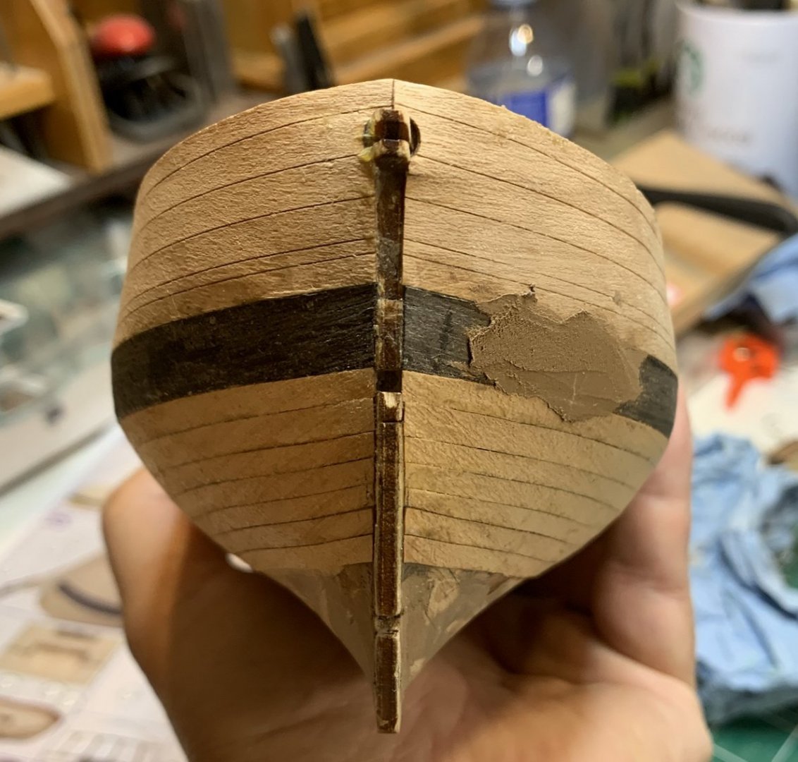
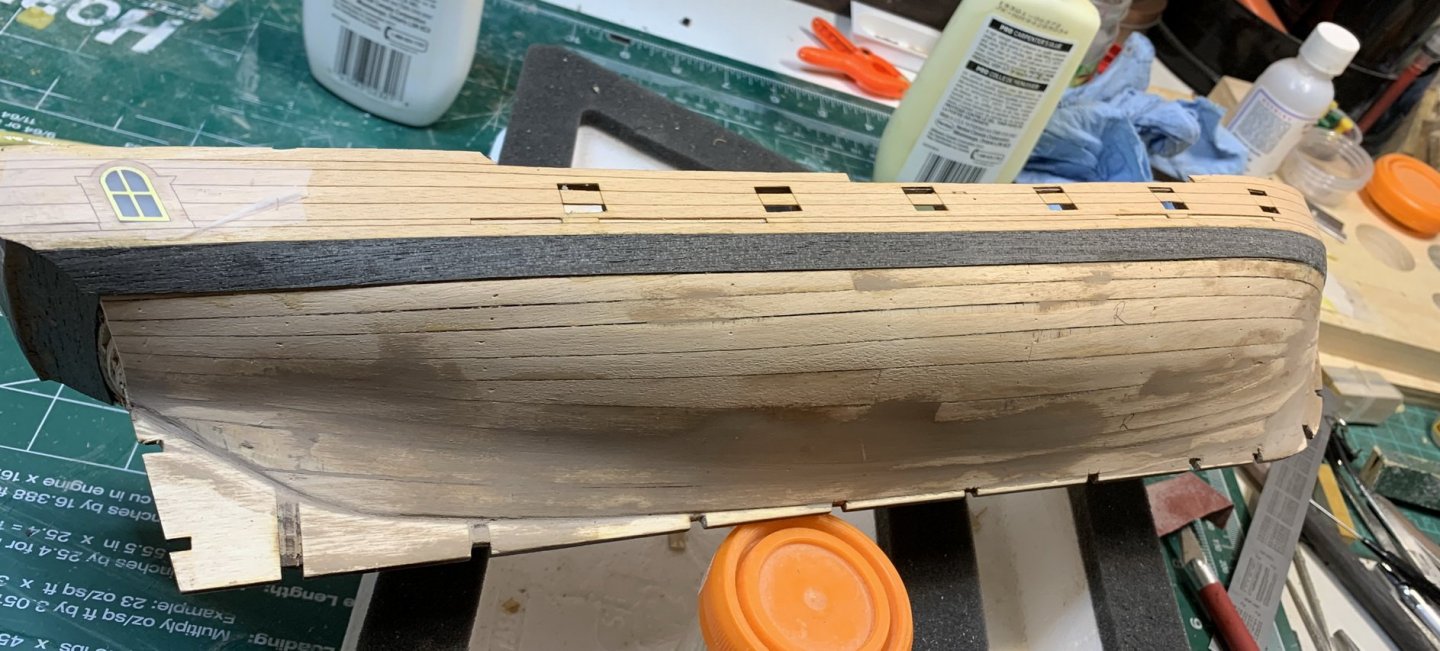
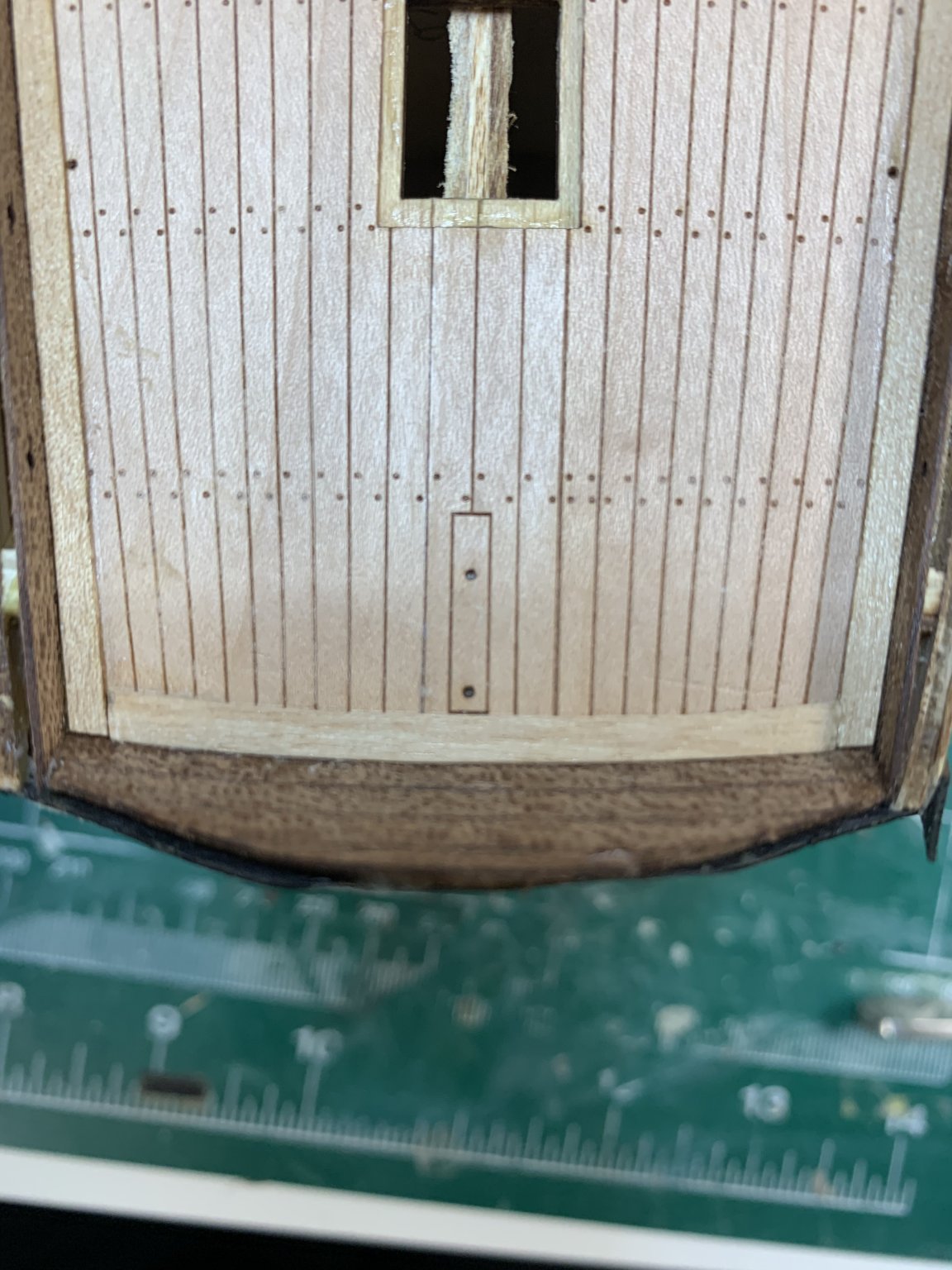
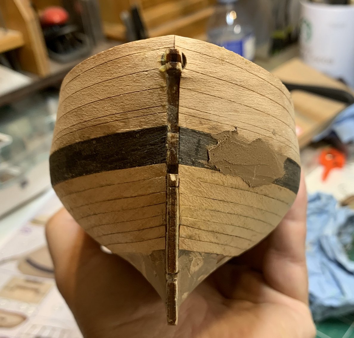
I decided to replace kit provided planks at the stern, just below the black painted area, with a home made from the spare pieces.. This is an idea from the instructional video...
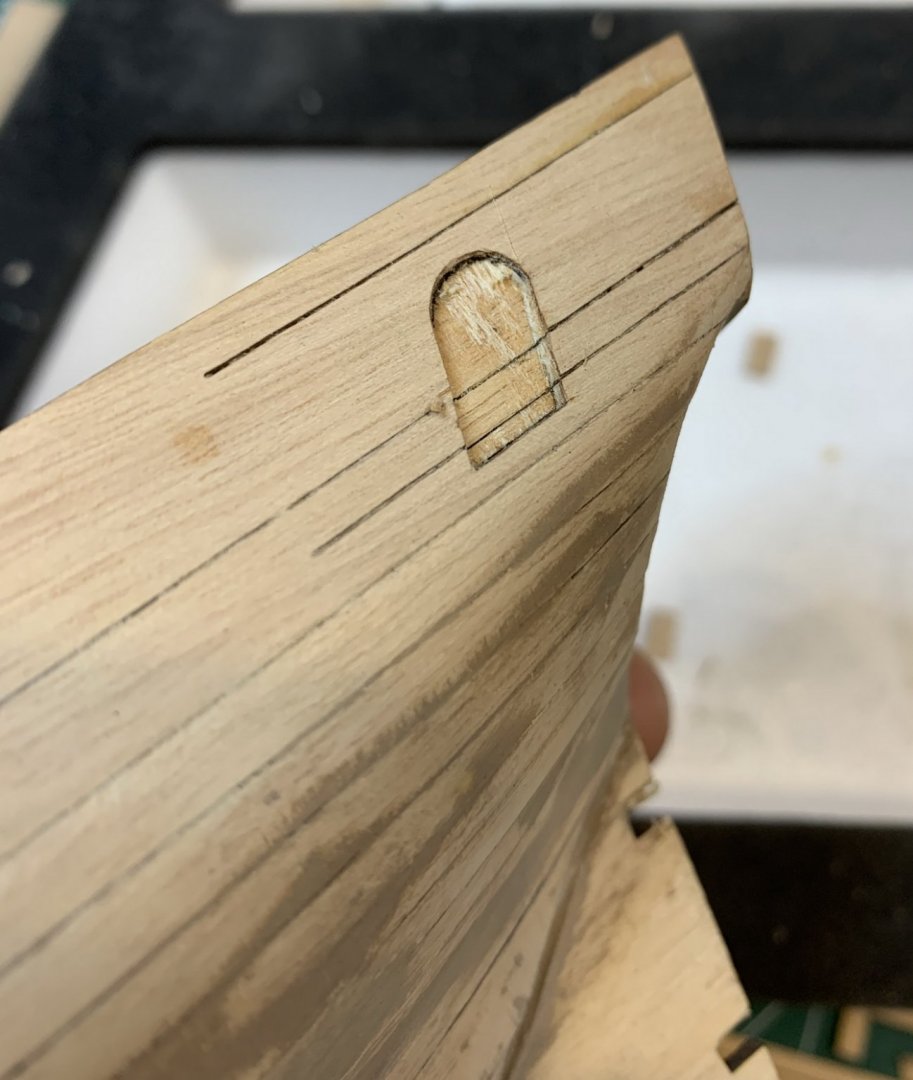
I have to reshape the rudder hole as well since i have replaced this part... and opening was not there...
Hull has been scraped and lightly sanded..
Few more parts glued and secured...
Happy modelling.
- CiscoH, Wahka_est, Edwardkenway and 1 other
-
4
-
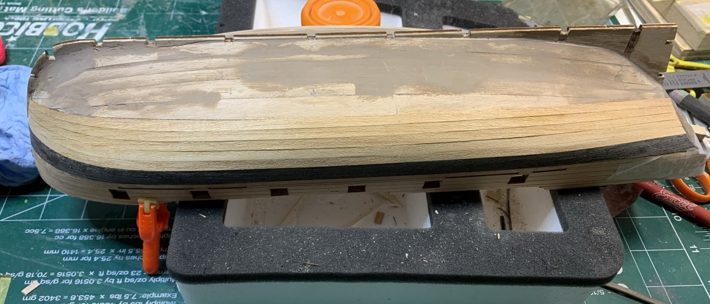
Planking keeps coming along just fine.... with not quite matching planking lines on both side of the ship, which i really do not like..


One of the very nice small details on this kit is a simulated steeler..
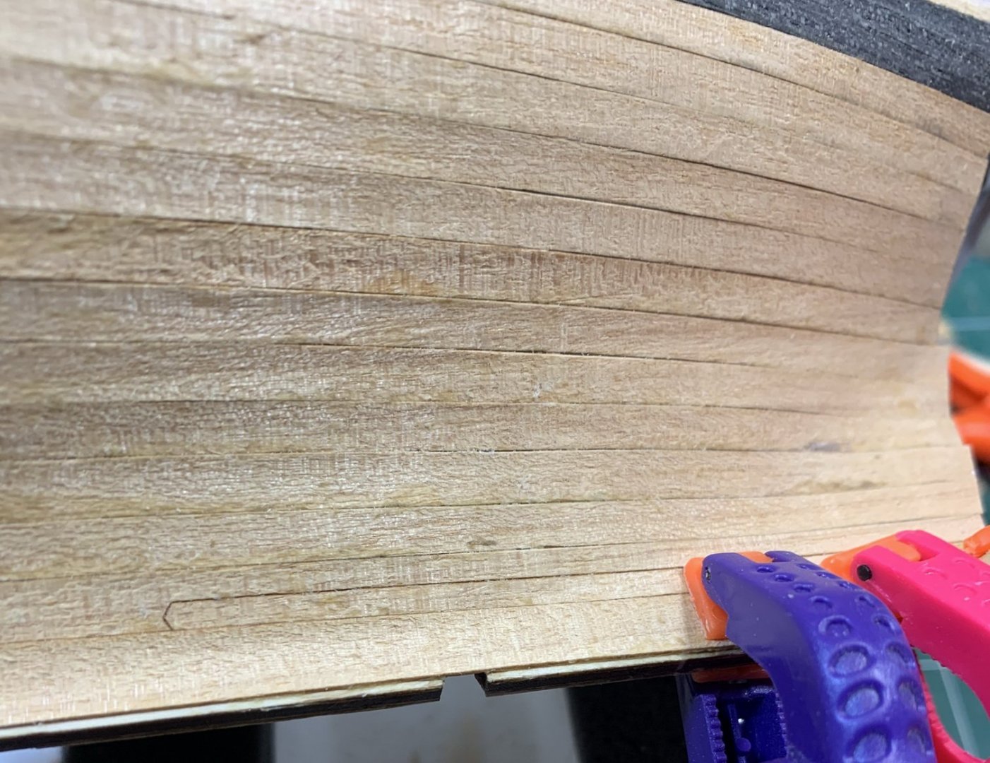
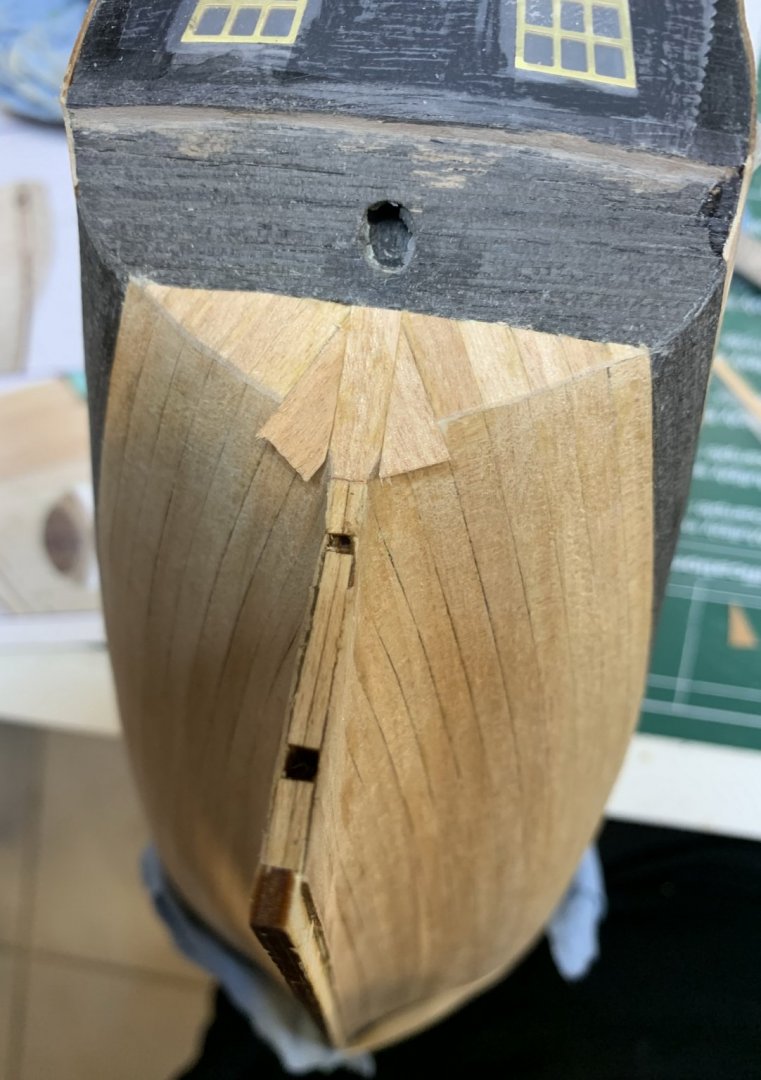
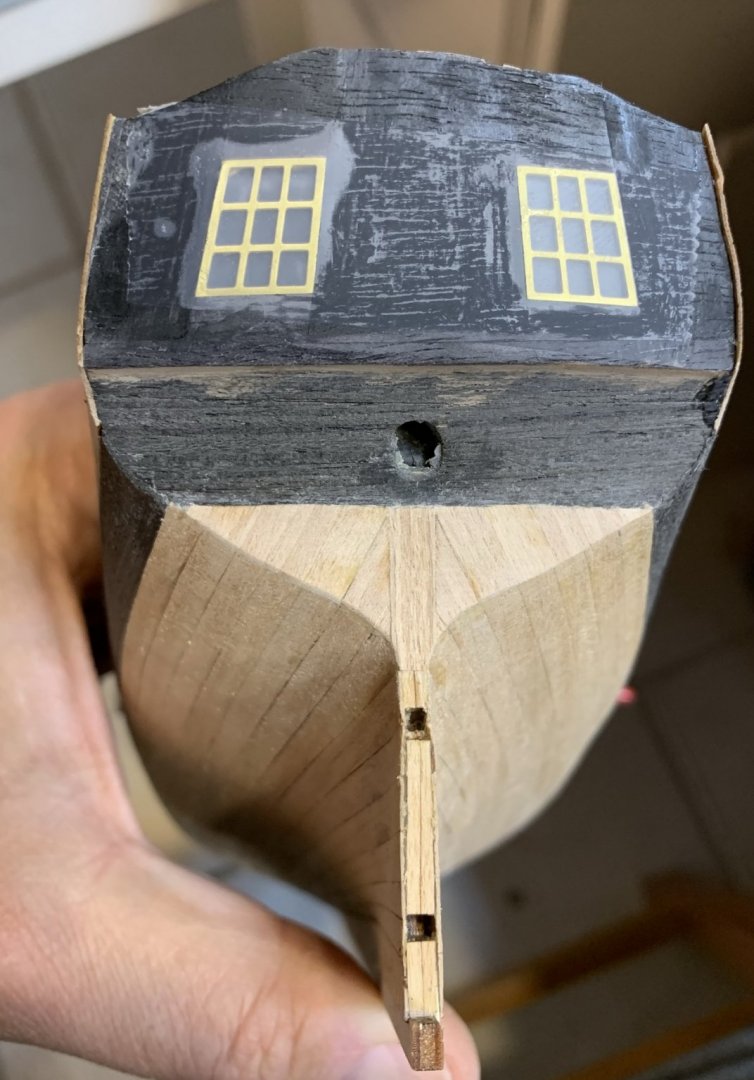
During this process i also discovered that i did not put planks properly at the bow. Maybe not reading thru instruction manual thoroughly but all planks have to go slightly over keel. There is very tiny amount of planks that is left on both ends once that plank is installed.
Anyhow, this is what i have to deal with..
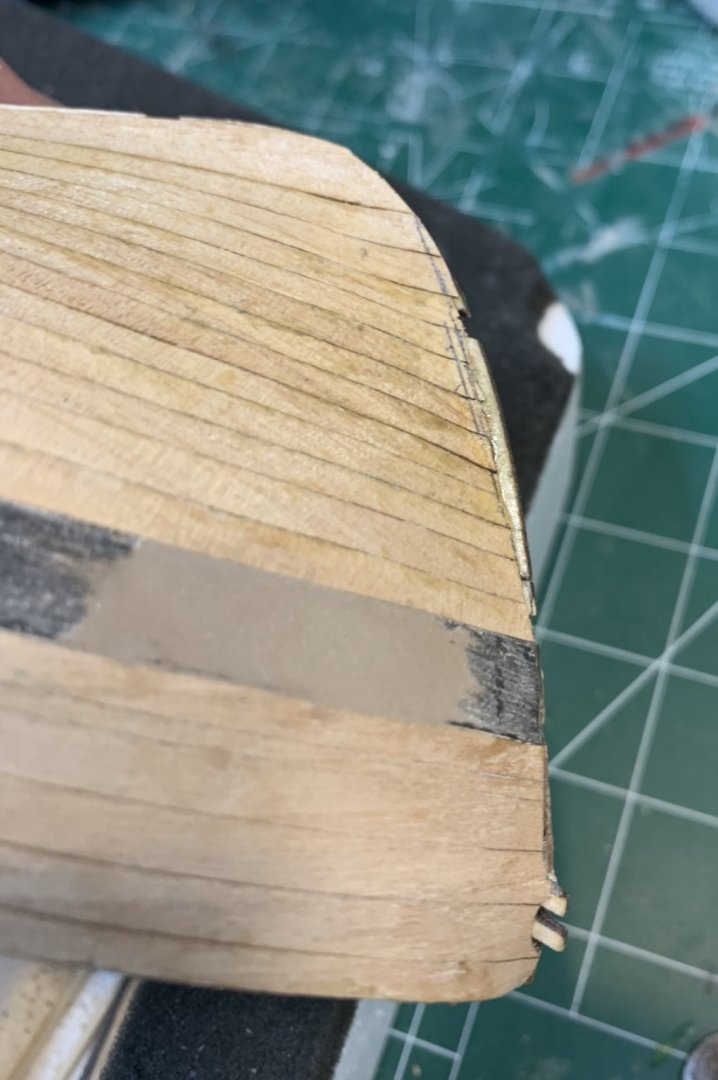
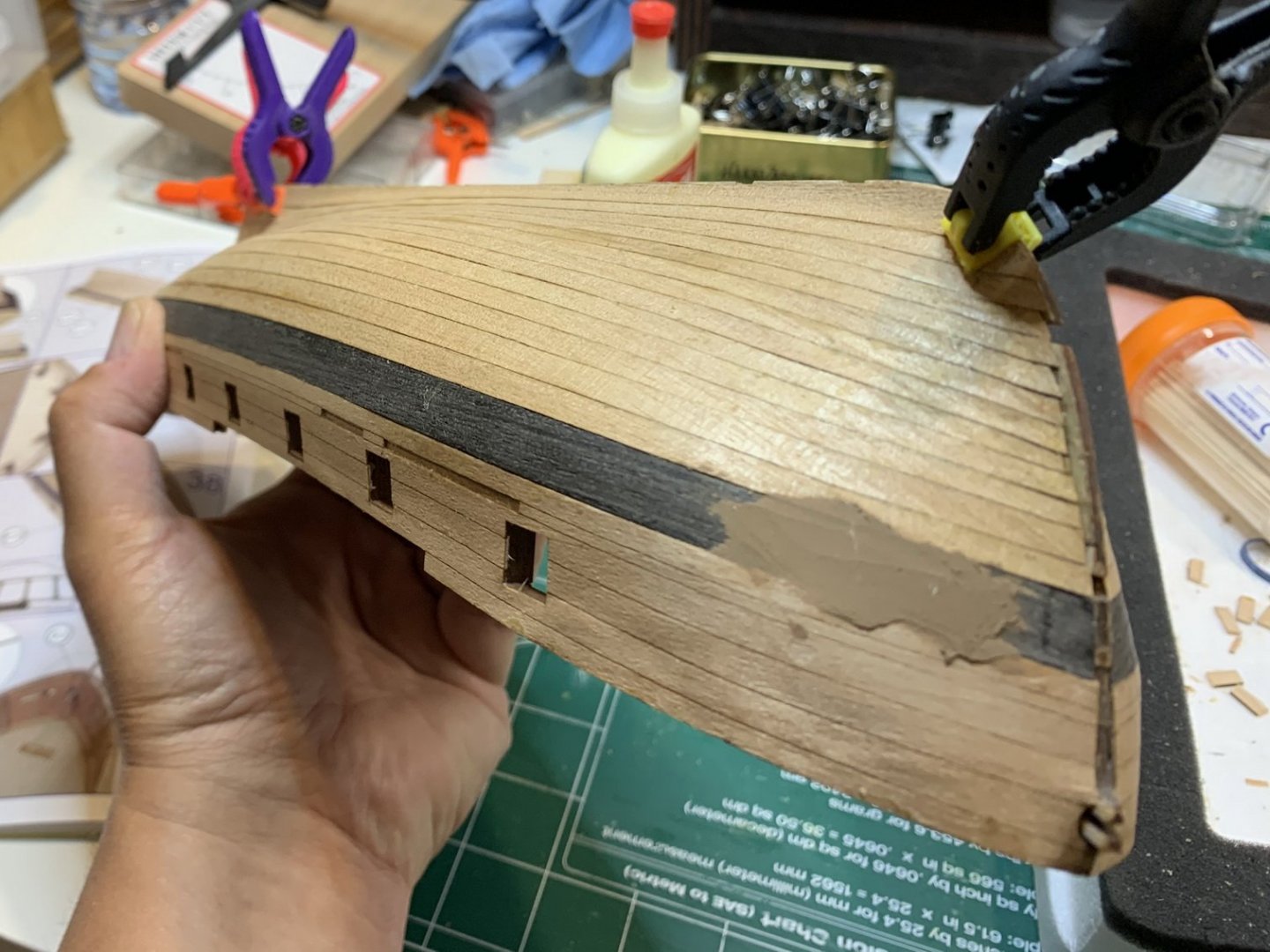
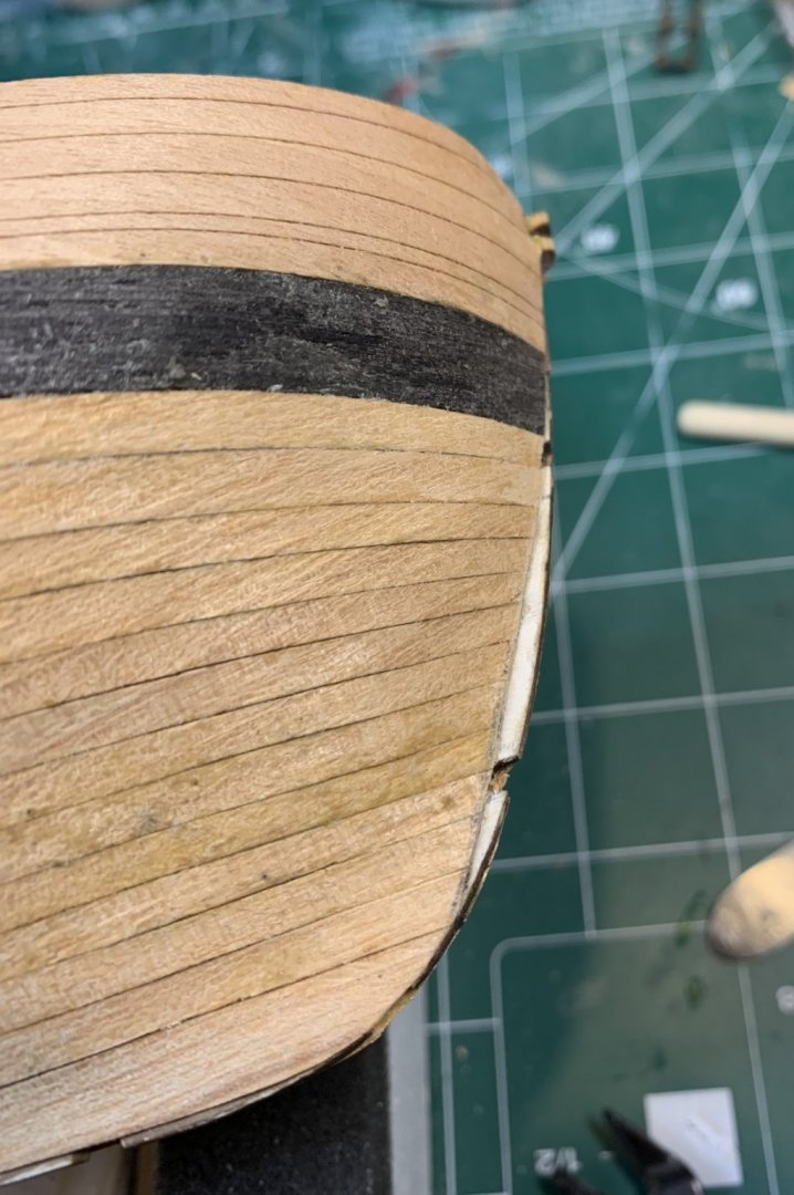
So i might ended up adding a piece of veneer that will cover this part and ended up on a false keel.... something like this..

Happy modelling..
- JpR62, Gregory, Edwardkenway and 3 others
-
6
-
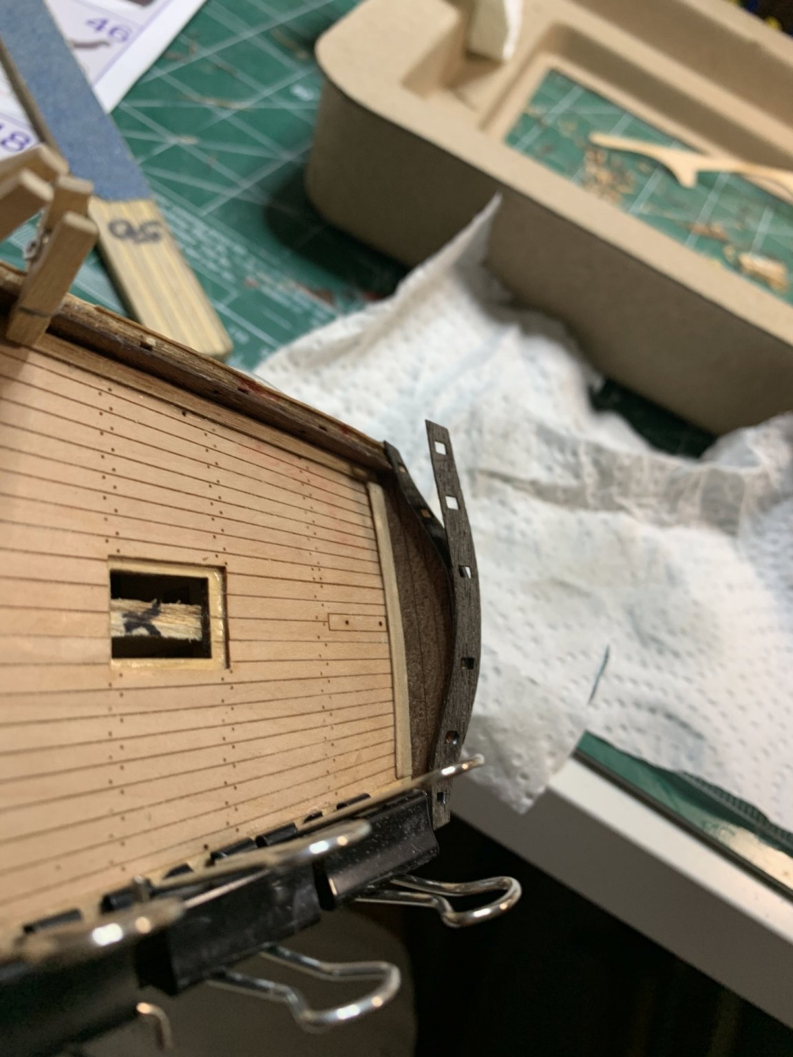
Window has been cut, sanded and installed. It fits perfectly on the top but the bottom end has tiny gap between window frame and planks...
Little bit of glue was applied around the frame to keep it in the spot.. and piece of scotch tap was applied over to protect it during work process on other parts of the ship.

Few planks were installed... They are long enough to leave some extras for trimming at the stern..
Happy modelling.
- CiscoH, Dutchman, GrandpaPhil and 1 other
-
4
-
The window frame was cut, sanded and assembled on the model. Window is then protected with a scotch tape..
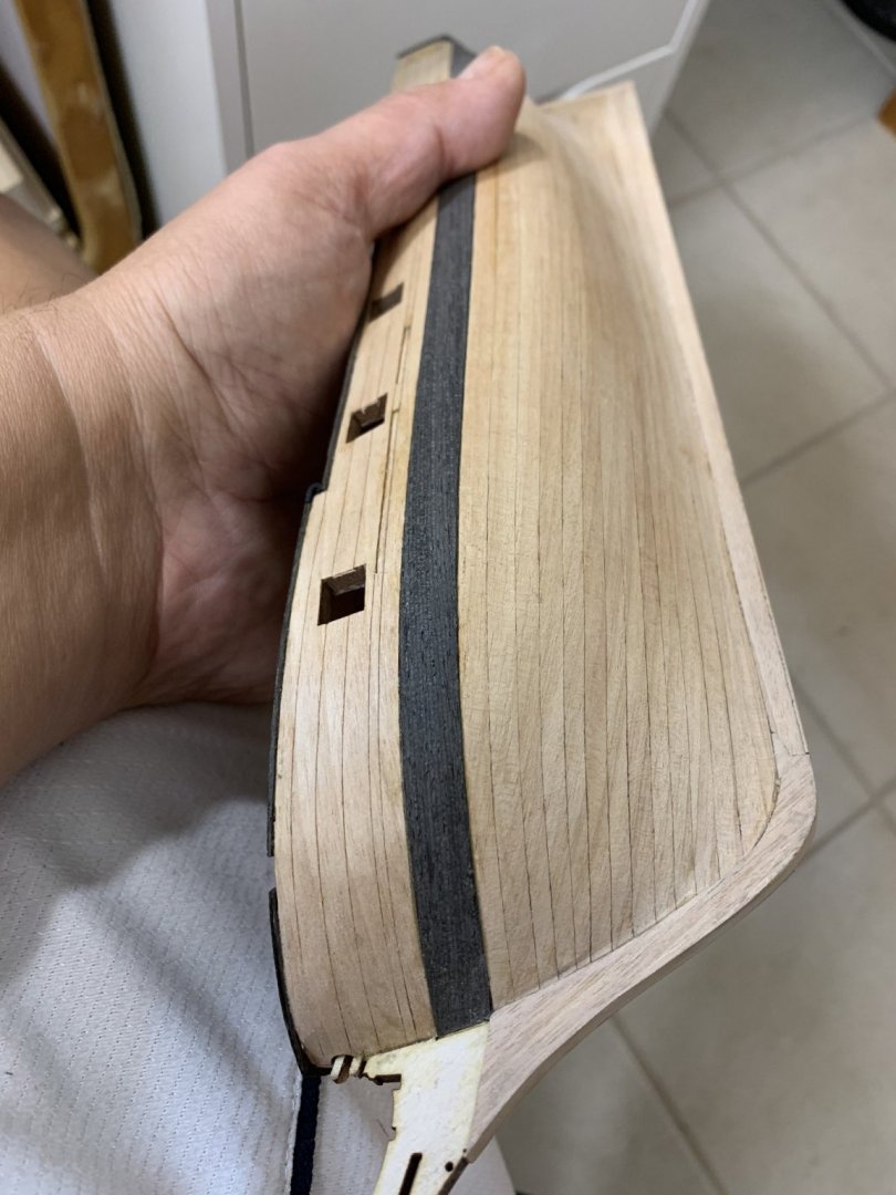
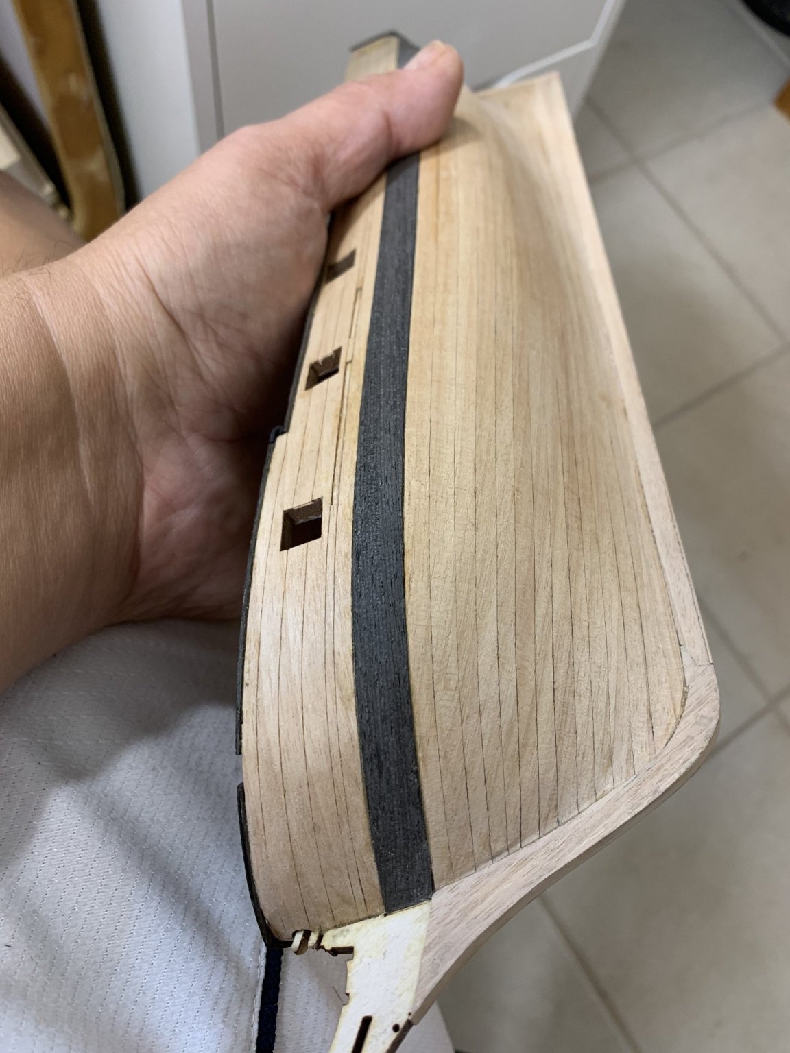
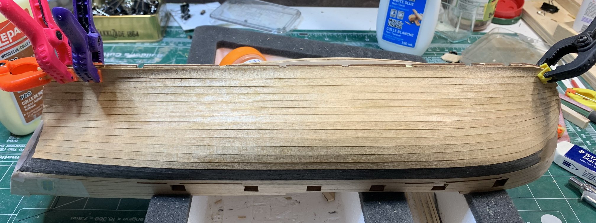
The wale was next, it consists of two piece of veneer for both ship sides. It is laser cut but still does require very slight sanding on edges which is absolutely not a problem at all. 🙂
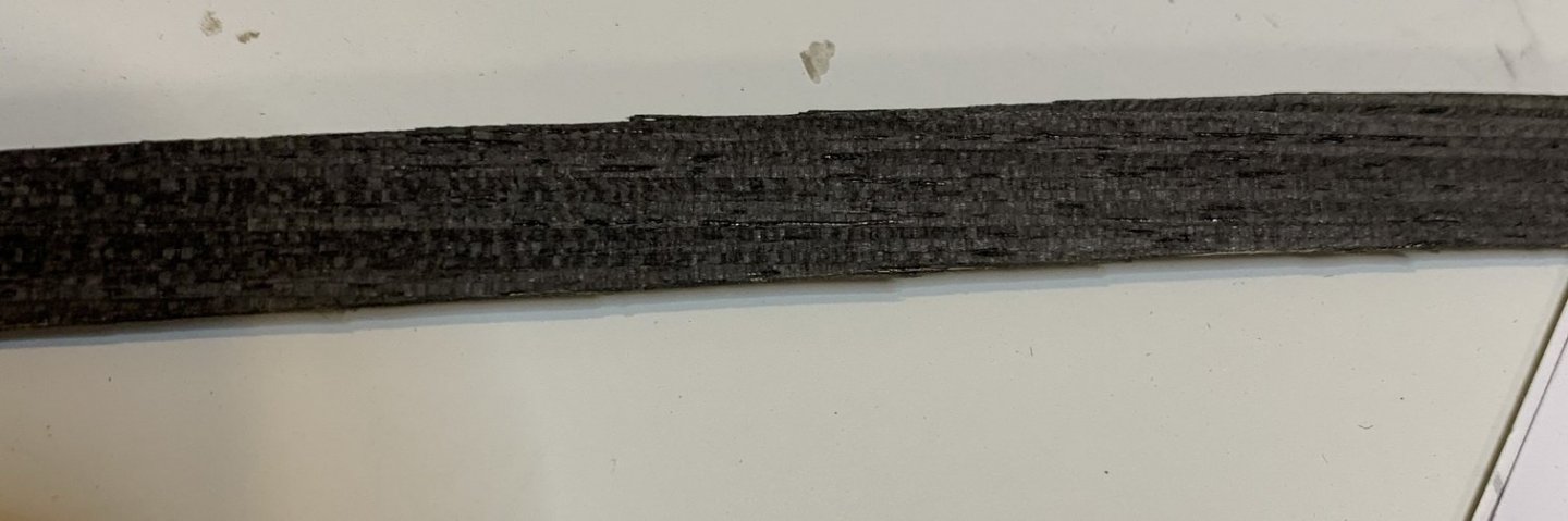
Just for fun, first i applied glue on the hull instead of wale..

And wale is attached, no issues here. All fits perfectly... Started from bow and made my way back...
And the port side first plank was applied.
Tomorrow will continue planking using hot iron technique to see how that does..
Happy modelling.
- GrandpaPhil, ccoyle, CiscoH and 2 others
-
5
-
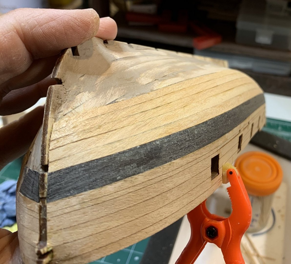
The inside frame of the gun opening was covered by veneer; extra veneer was removed and sanded flush with the hull.

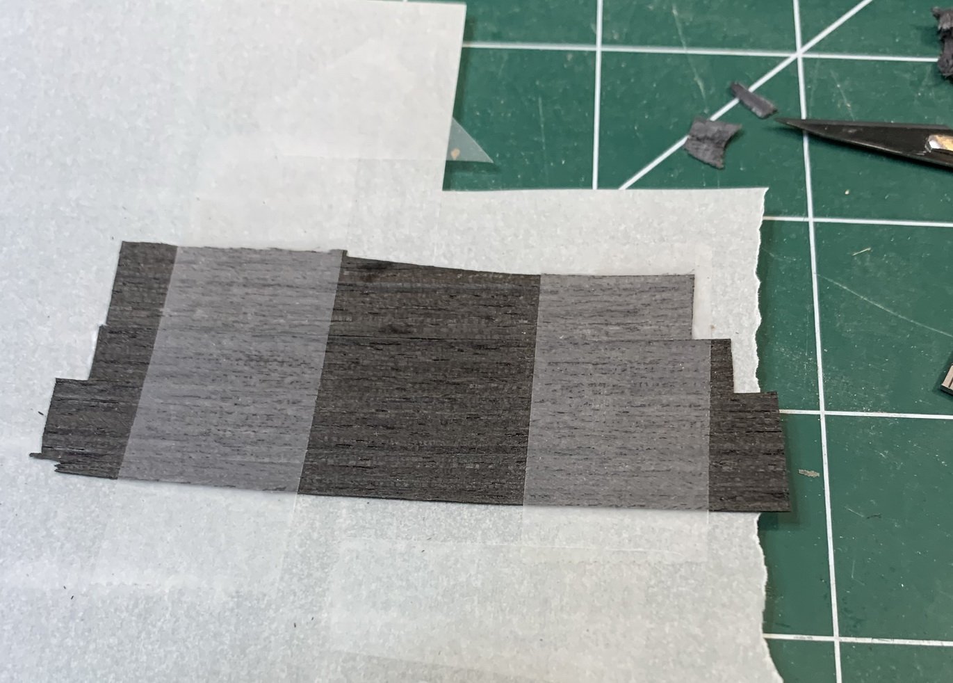
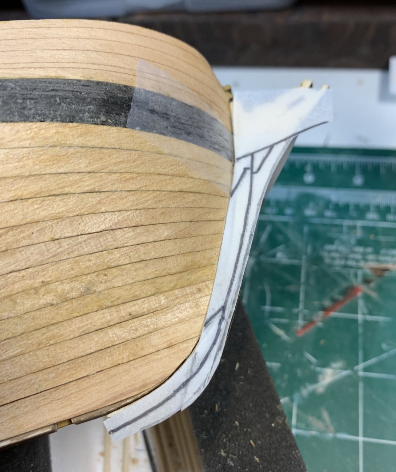
Work on stern continues repairing broken piece... several planks were made out of spare veneer, glued to the transparent paper, cut in rough shape, and then, as a whole piece, glued to the ship. I could probably do it gluing individual planks but..
Making sure it stays put...

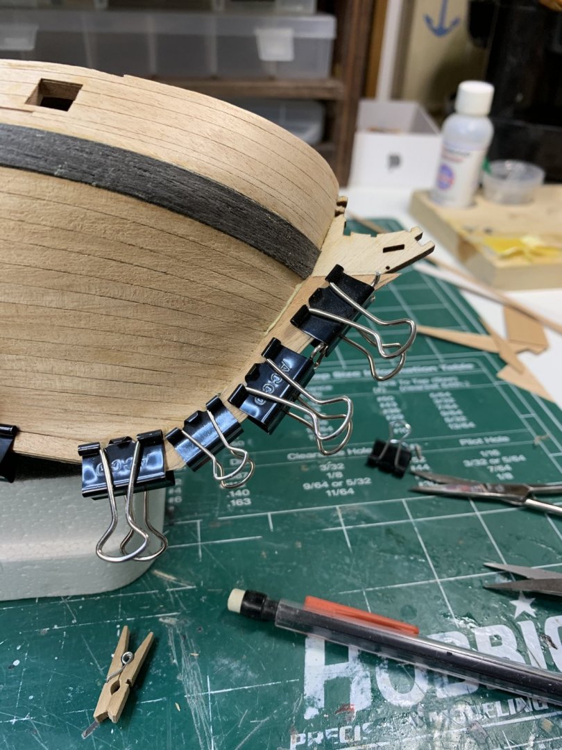
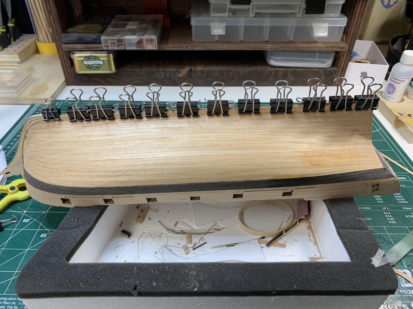
After this the first second plank was installed. It takes a bit of positioning, but if you start from stern, slowly, securing it with either rubber bands or other clamps, it can be done with no issue.


Plank at the bow required a bit of extra attention.... Tomorrow..

Happy modelling.
- CiscoH, GrandpaPhil, Wahka_est and 1 other
-
4
-
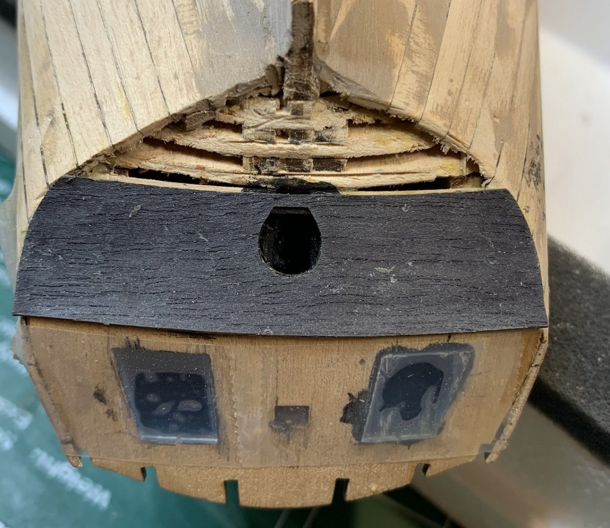
Continuing working on inner frames for gun openings... moulding were cut in 9mm length, glue applied on the frame and veneer piece pushed in. Then i sanded all parts that are sticking out and made them flush with the outside planking. Few more to go... i did not work on inner edges yet..
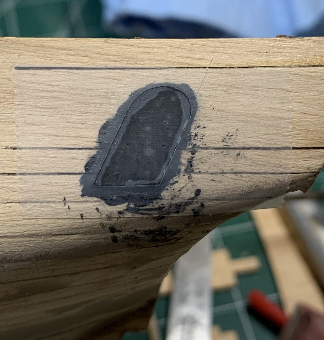
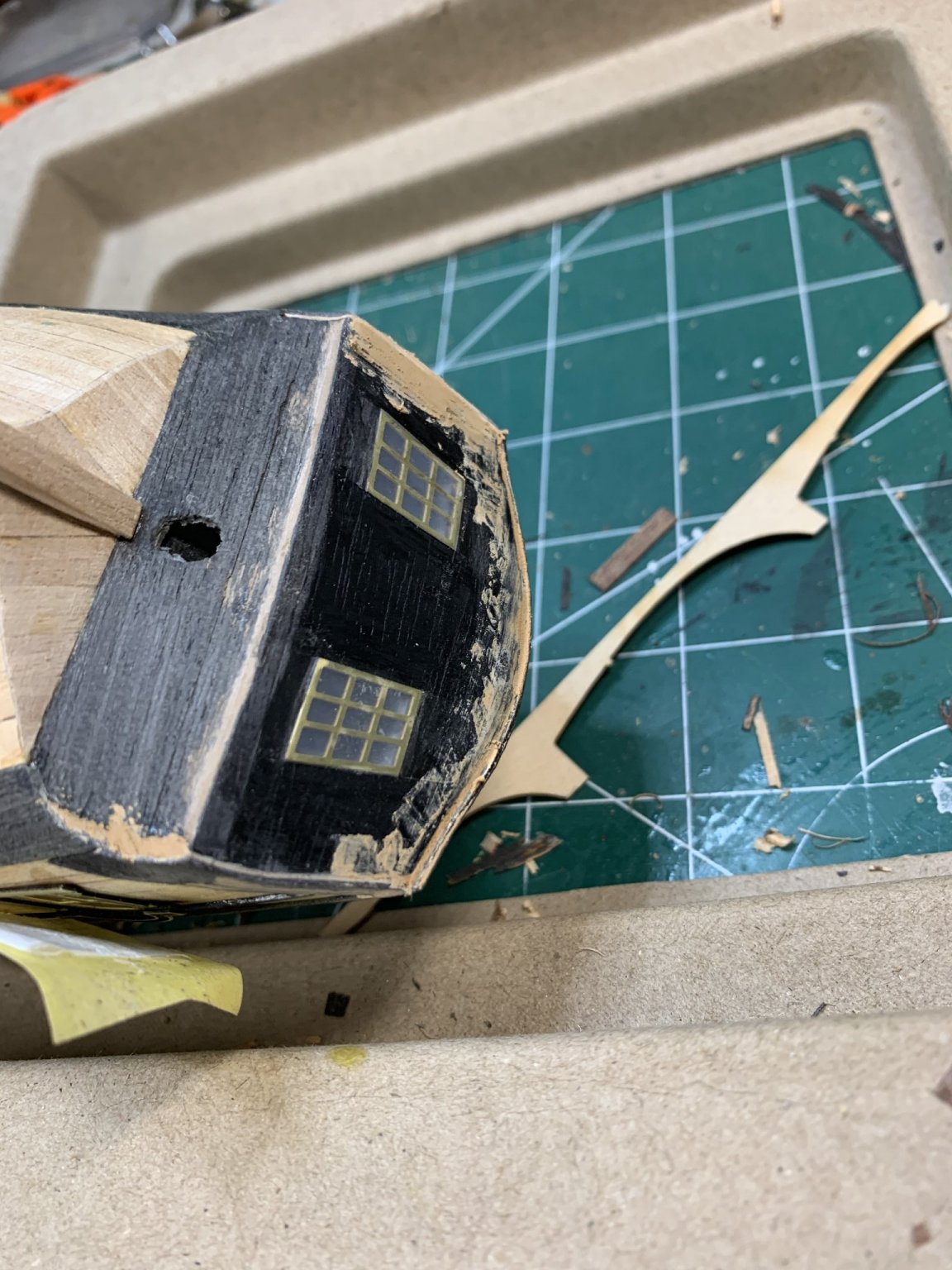
A bit of a work happened on stern as well.. Area previously filled with wood putty was sanded and ready... Veneer part was sanded lightly and glued on the stern..

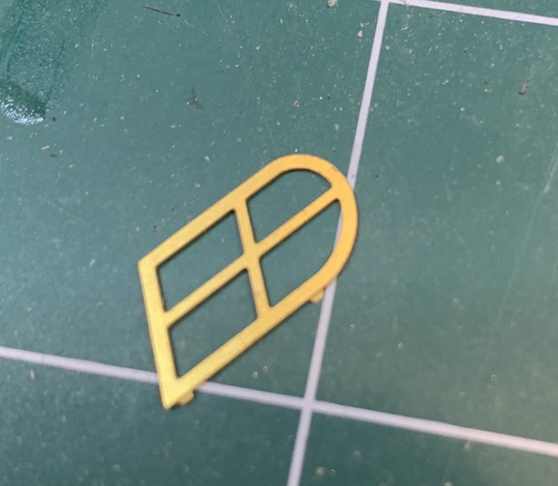
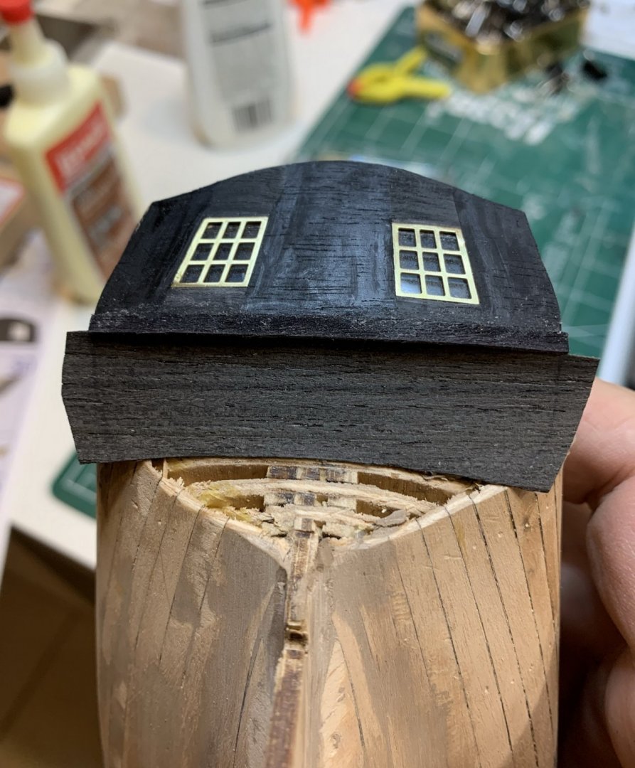
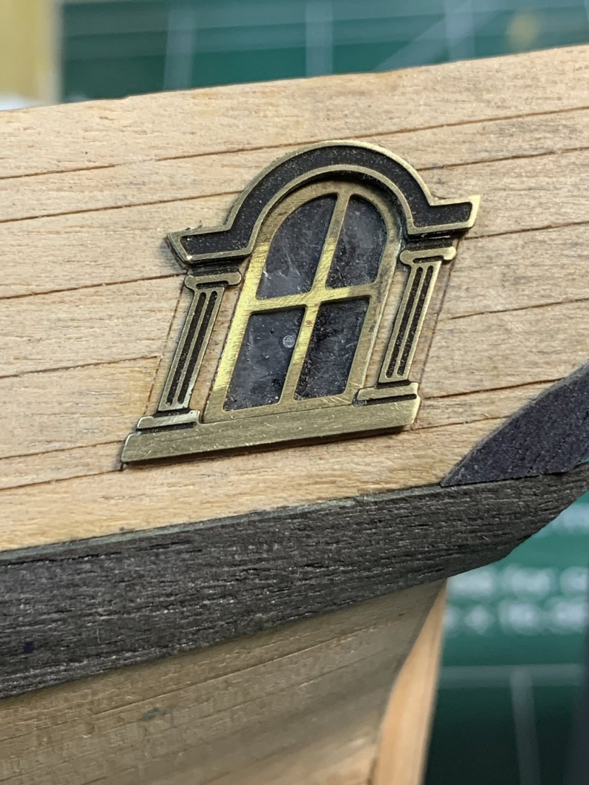
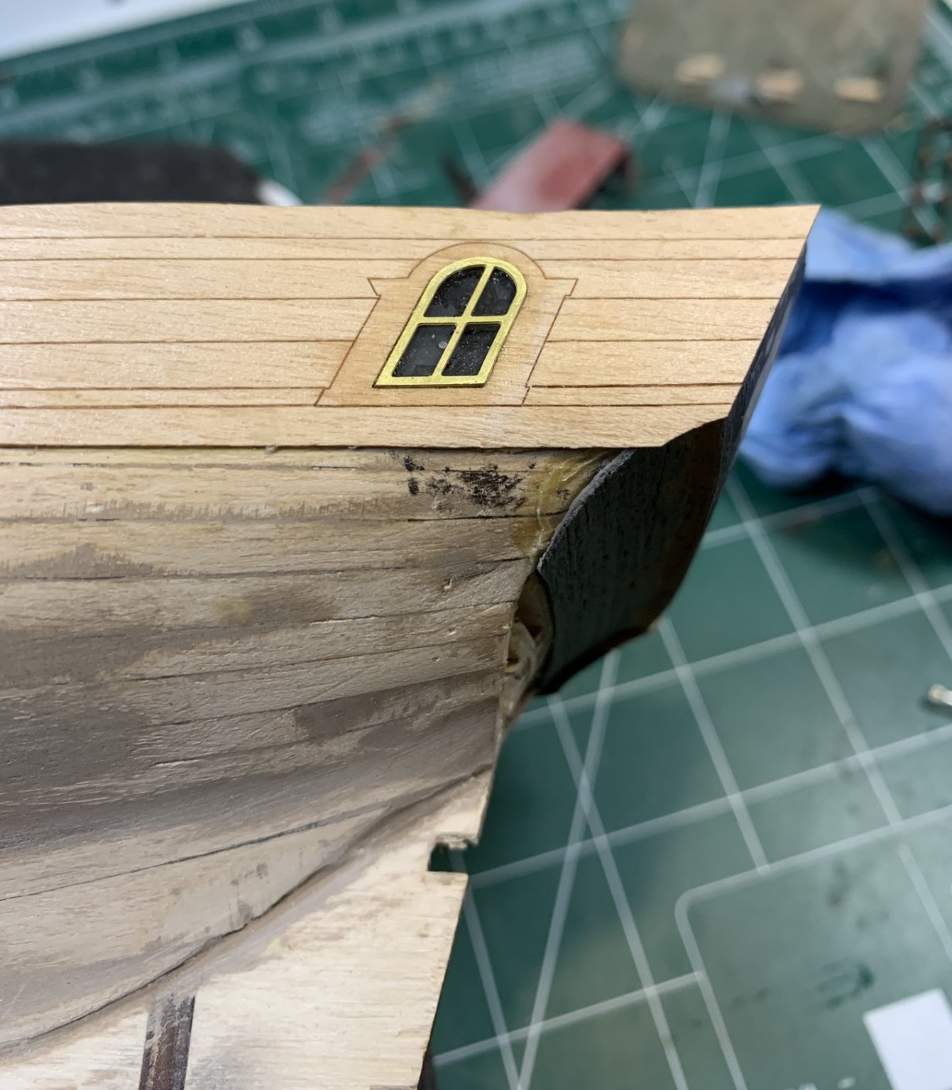
Windows were cut of and sanded lightly...
.. installed in the window openings..
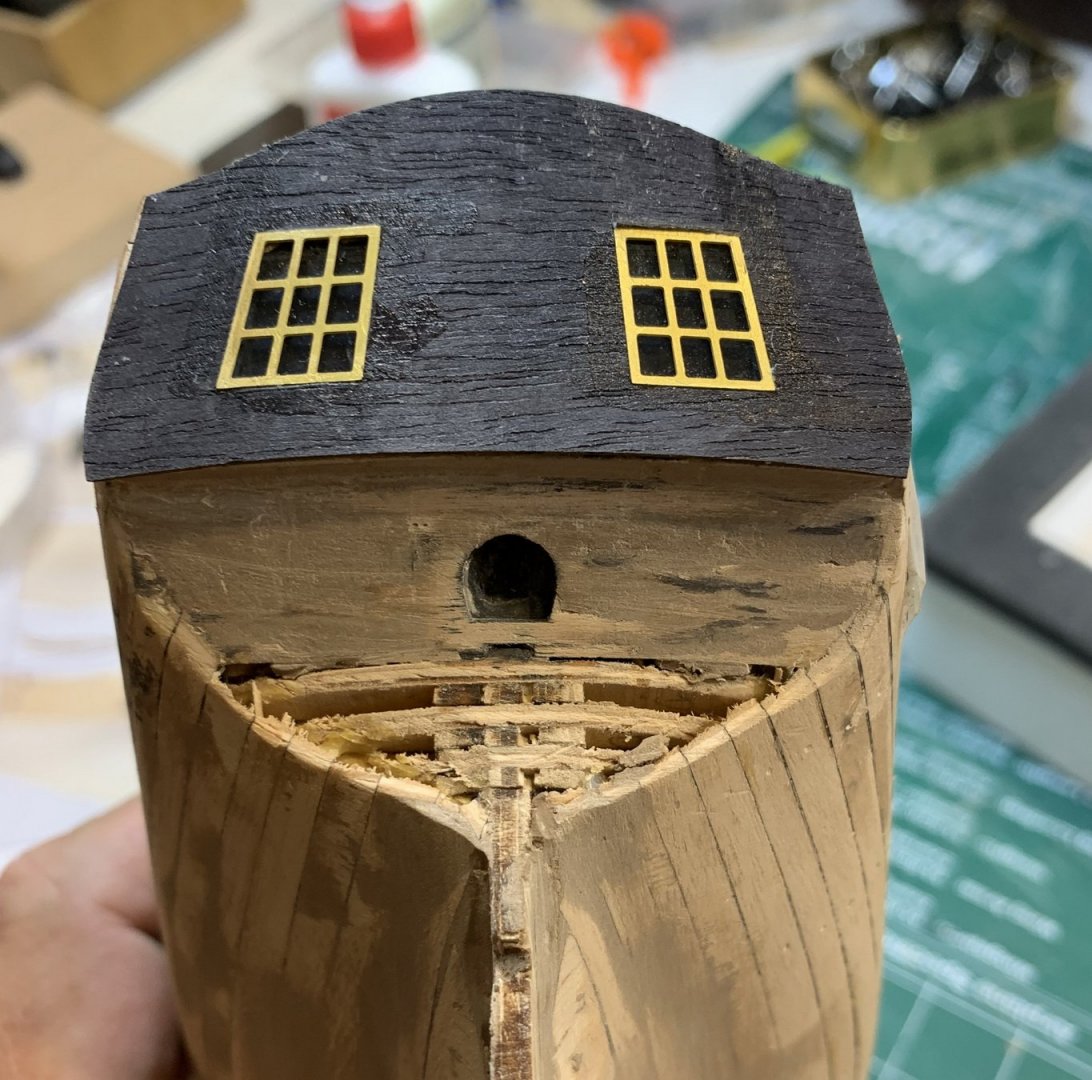
Even dough i have applied a minimum amount of glue around windows, some glue leaked out and cured showing some discoloration on the veneer. So i run a tiny layer of black paint all over the piece. Still need to protect window frames and finish painting.. this is for today

Hopefully this will correct glue issue. Now i will paint all black veneer pieces so they all matches....
Happy modelling.
- Dutchman, Edwardkenway, JeffT and 3 others
-
6
-
10 minutes ago, Wahka_est said:
Noce work! Totally agree-everything is so fragile... But good thing is that their laser cut sheet have that extra material to cut replacements-guess it was designed like this.
Doing Polotsk myself right now and Phoenix is definitely one of my future kits if MK dont come out with something bigger.Thank you..
Yes, it is very good kit overall, certainly a different approach in ship building area..but still with options to change if needed... I am also looking for bigger kit from them
With this work from home stuff i have a bit more time for hobby 😇
-
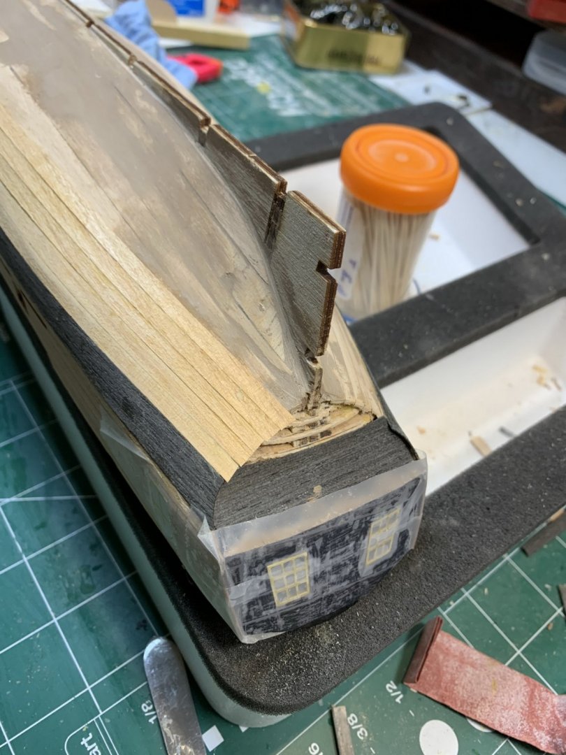
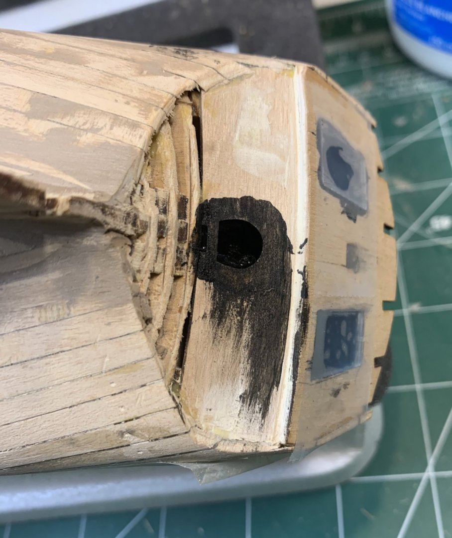
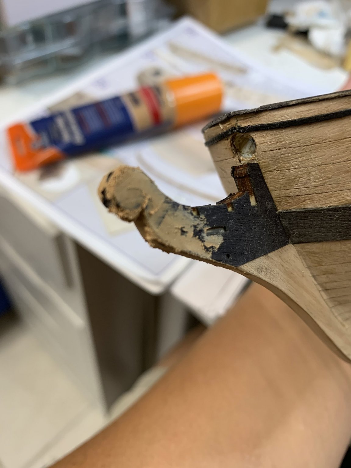
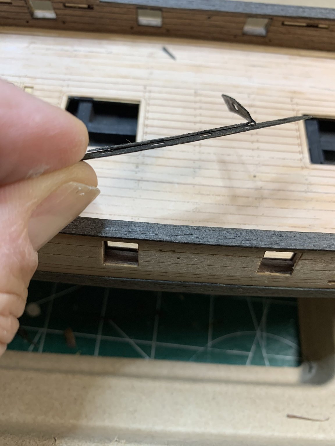
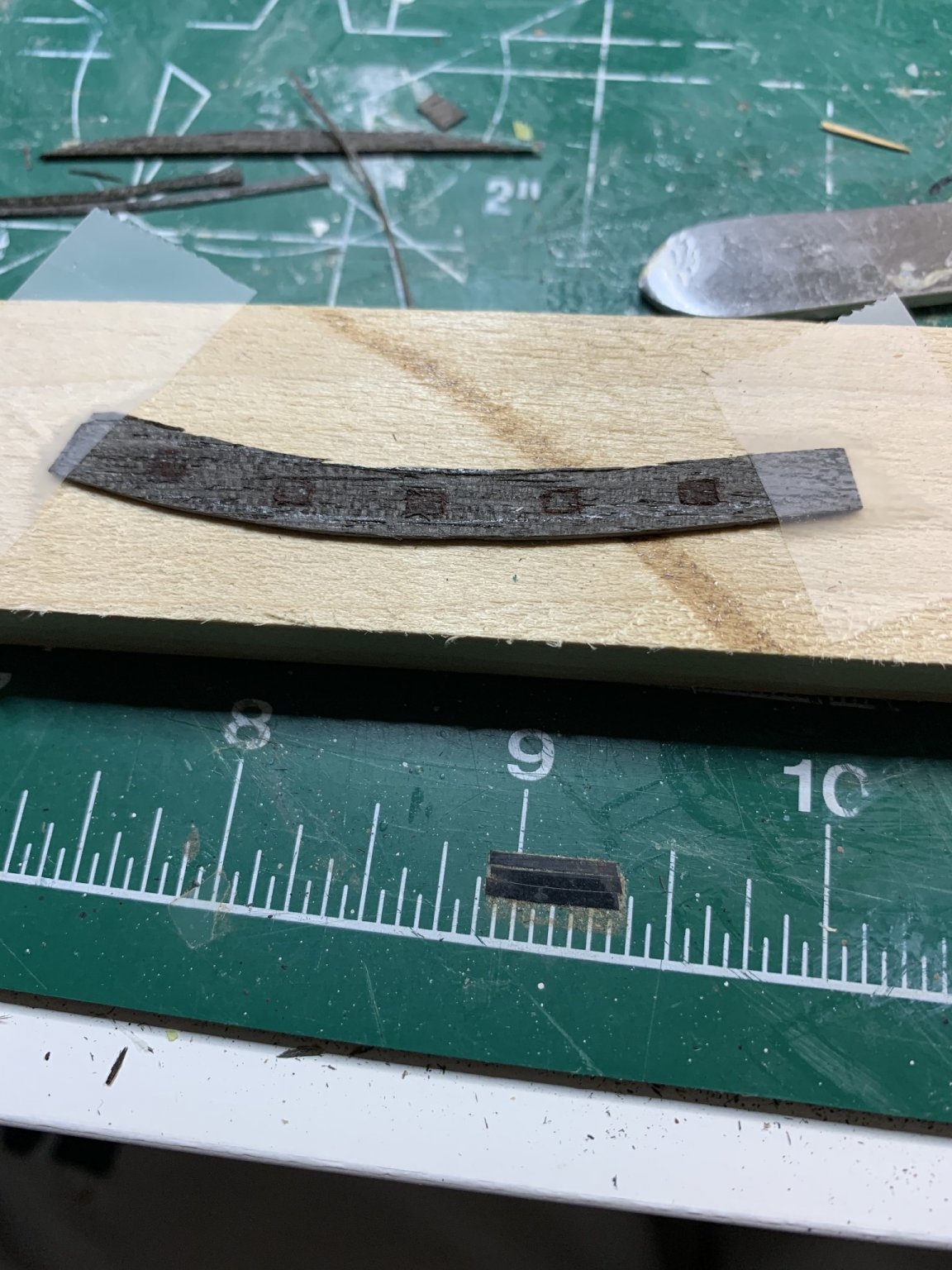
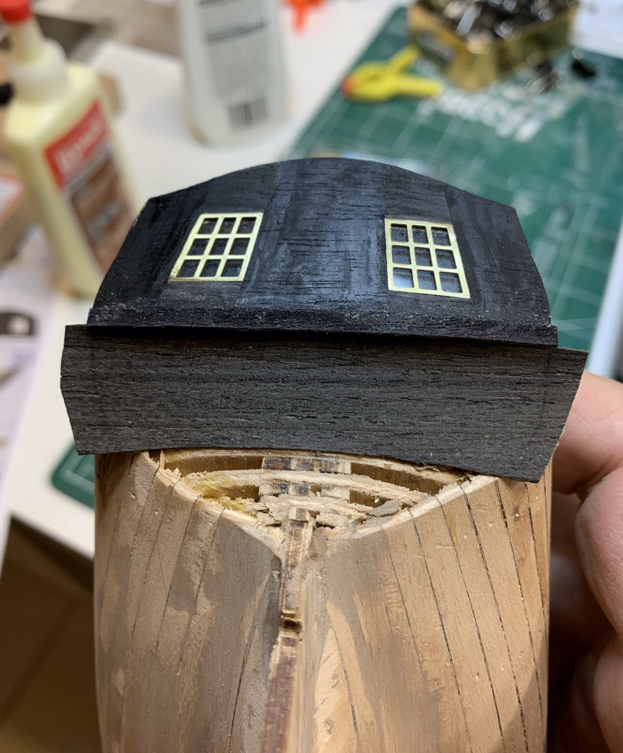
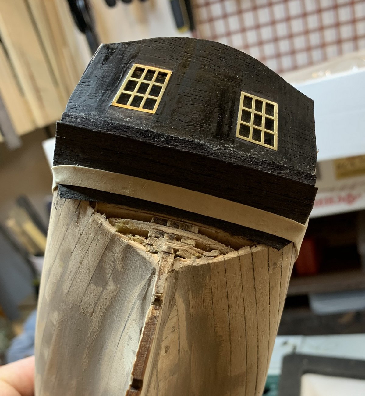
A little bit of a damage was caused by not being careful around ship yard and accidentally broke the black piece planned to install on stern...
Testing fitting before gluing while piece was still intact...
Veneer sheet is very fragile and now i have to make another one out of a spare part.. First cleaned up area and covered with wood filler.
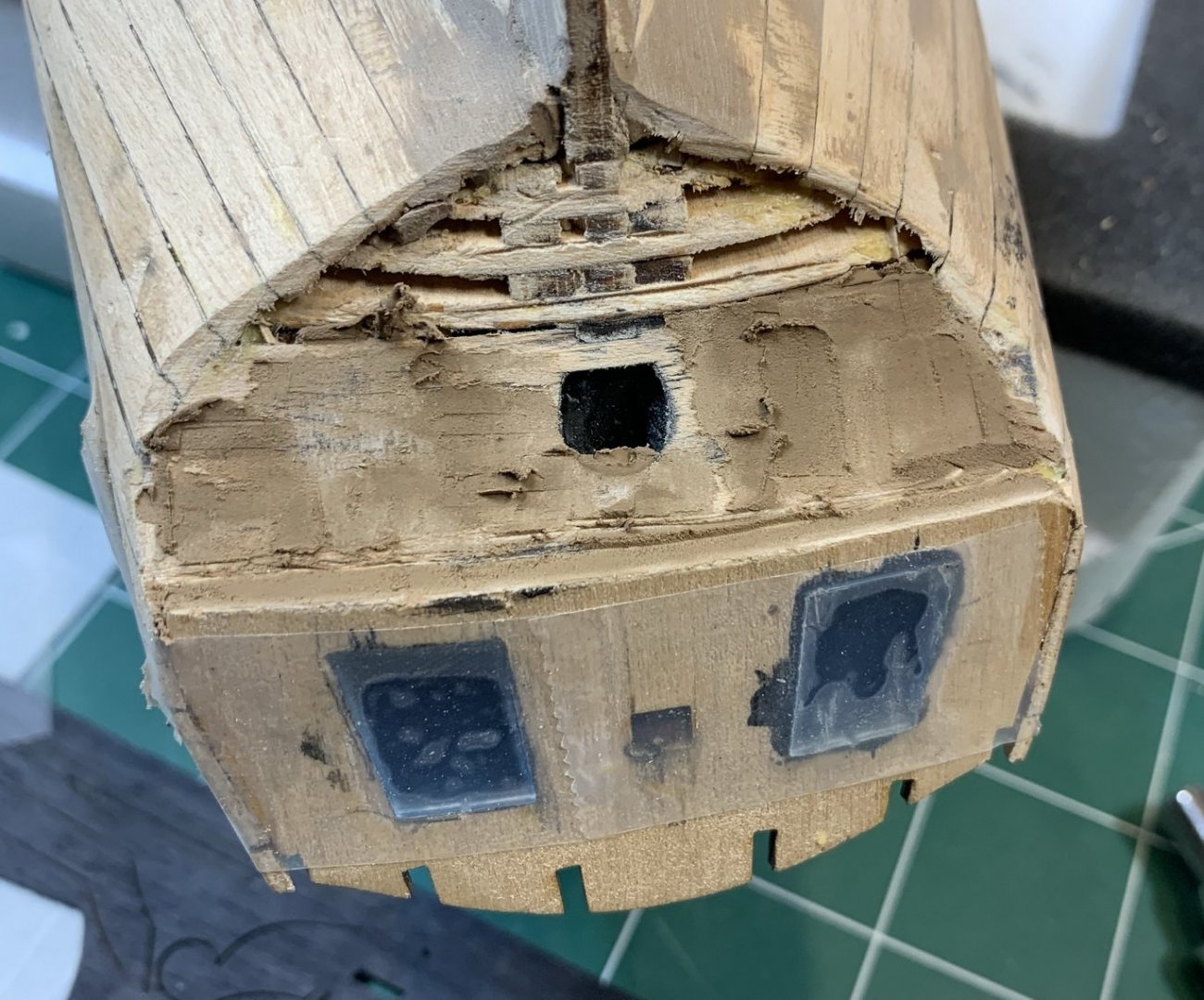
While this is drying i started to make replacement..
Trace it on transparent paper...
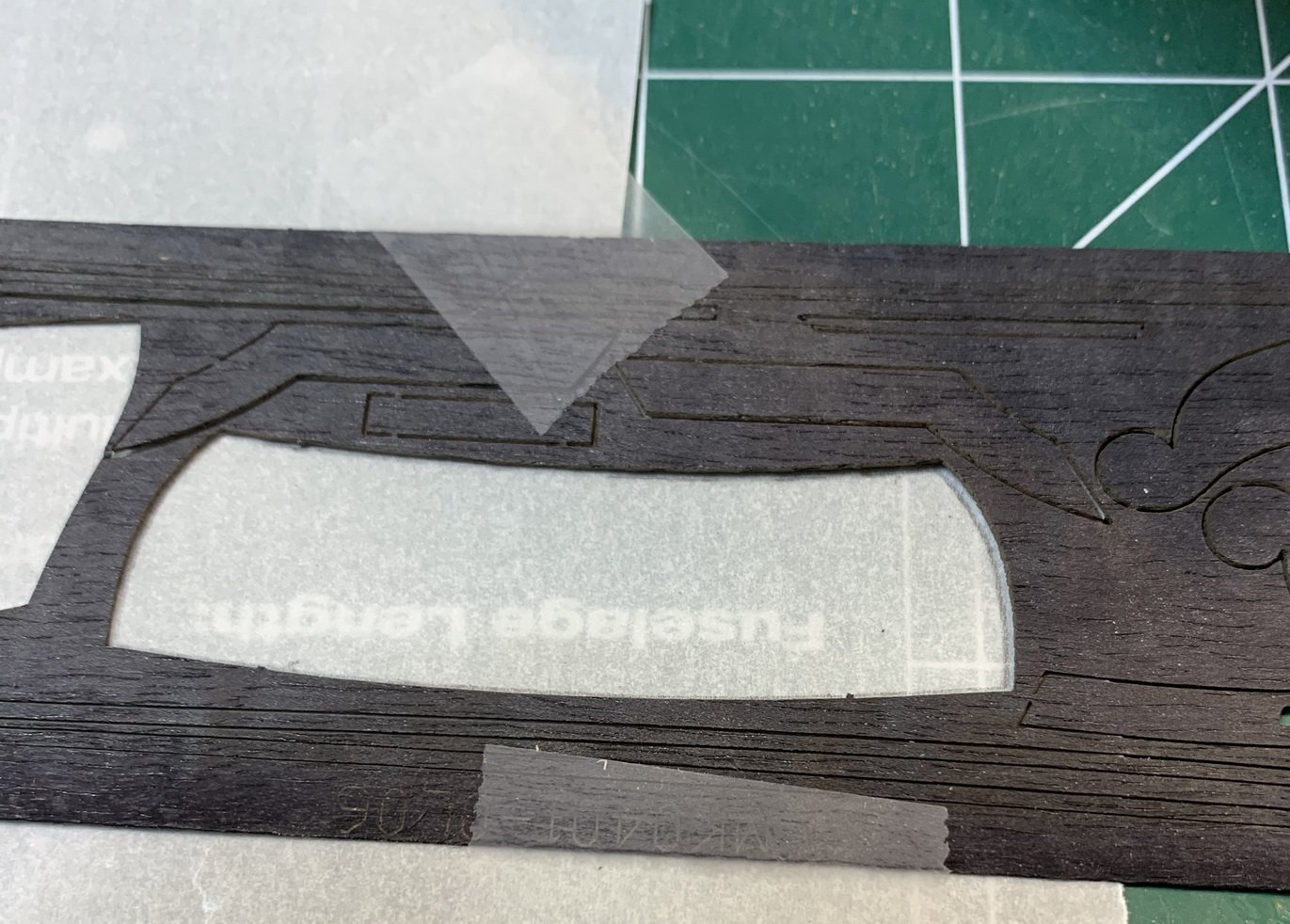
Glued few spare planks on the paper...
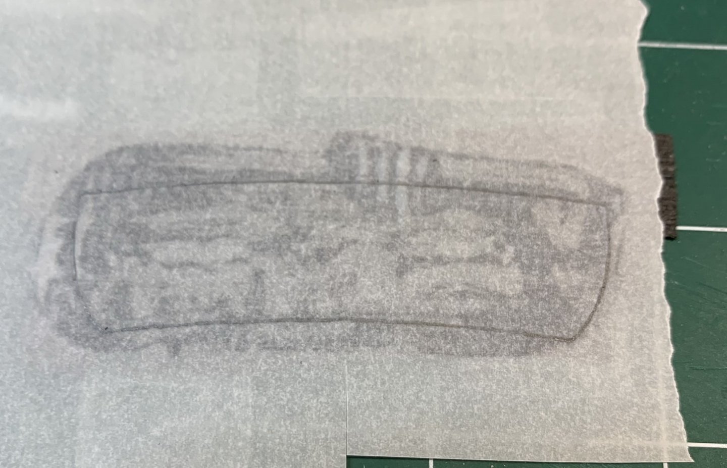
Planning to leave a bit of extra wood around tracing lines just in case if i have to adjust fitting. While this is drying i cut several moulding pieces that will fill inner frame of gun openings..

And one glued in...

Not much progress today...
Happy modelling.
- Edwardkenway, CiscoH, Wahka_est and 2 others
-
5
-
The place where rudder will be mounted, has to be painted in black...
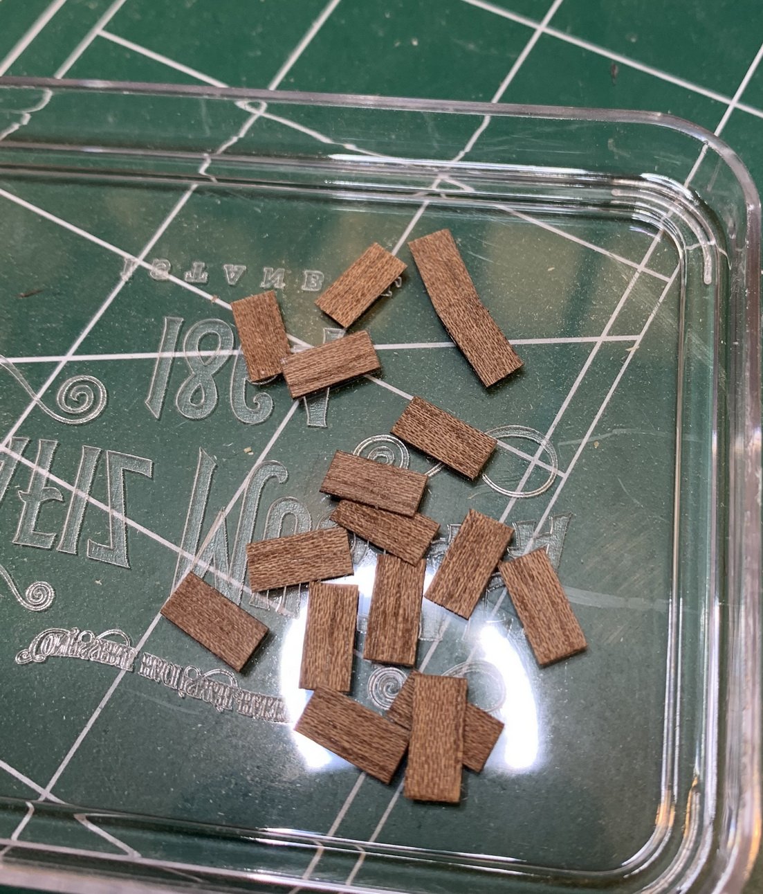
Then i start adding frames to the cannon openings; using miter cut tool..
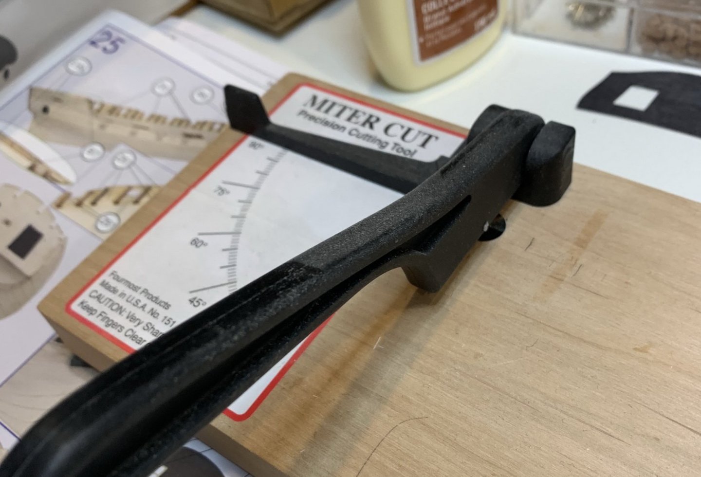
.. i cut 6 frames/mouldings that will be going on first. I happened to have this tool but forgot about it hiding it during my last workshop cleanup; any cutting tool will do the job, no problem.
Installed..
All 6 were put in place.. A little bit of moulding shaping is required to make it fit nicely. After gluing it, i sanded it with the hull..
Happy modelling.
- Wahka_est, Edwardkenway, JpR62 and 2 others
-
5
-
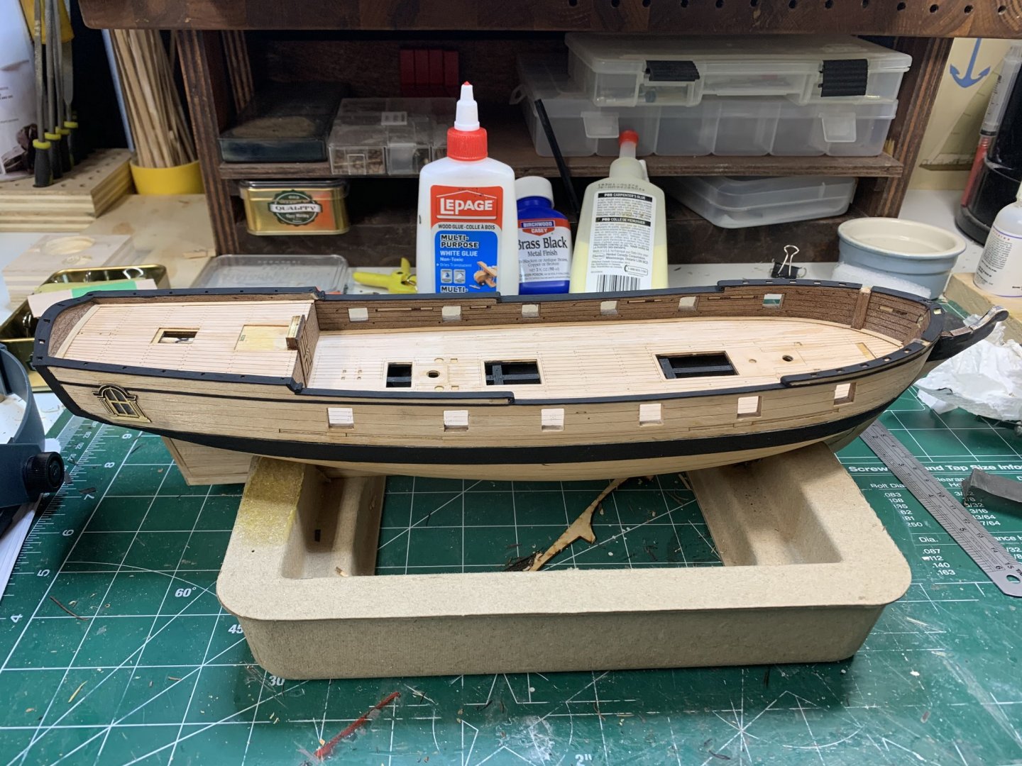
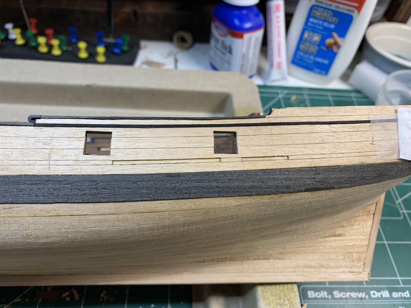
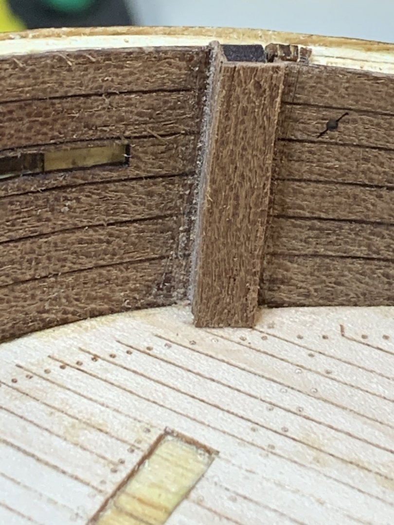
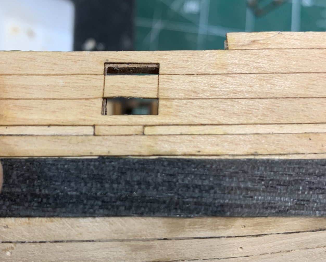
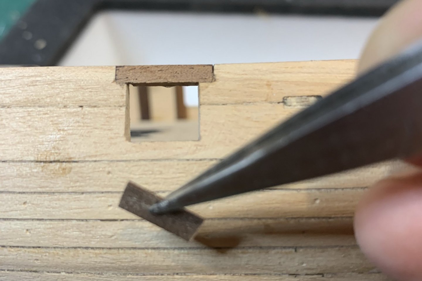
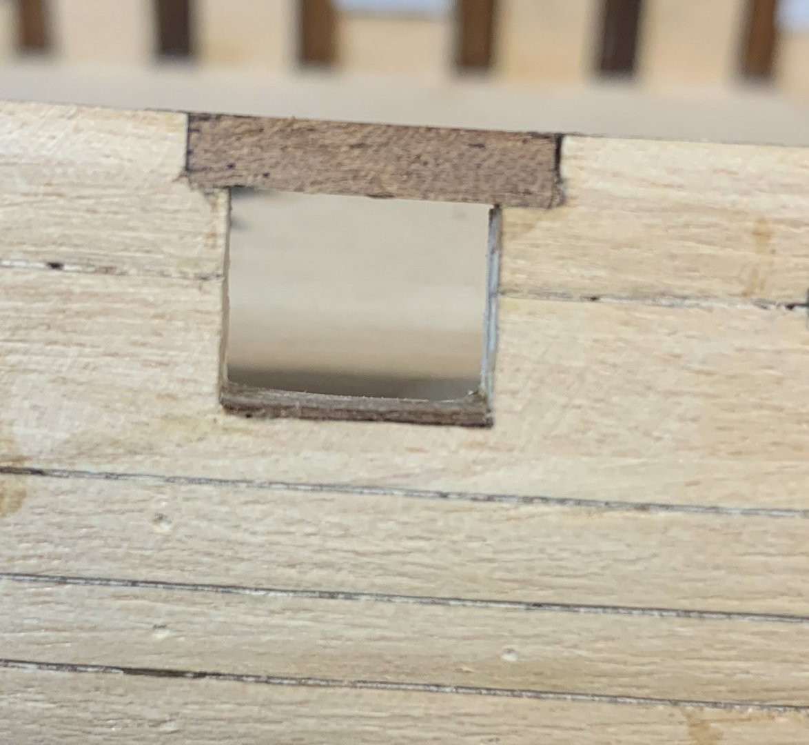
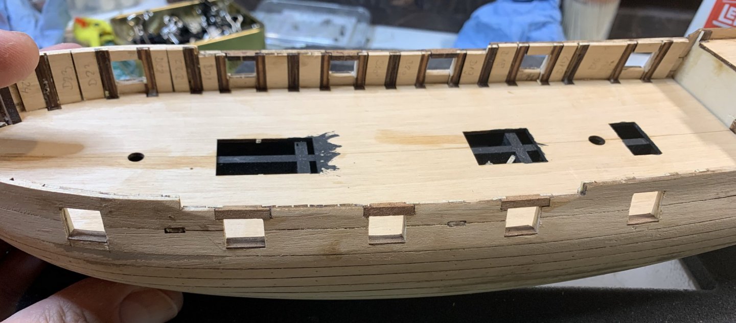
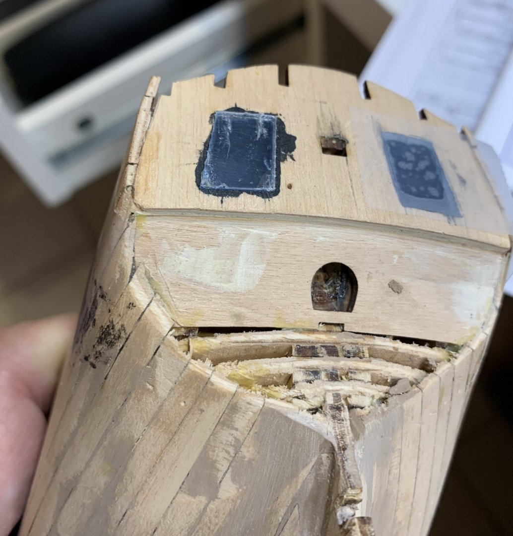
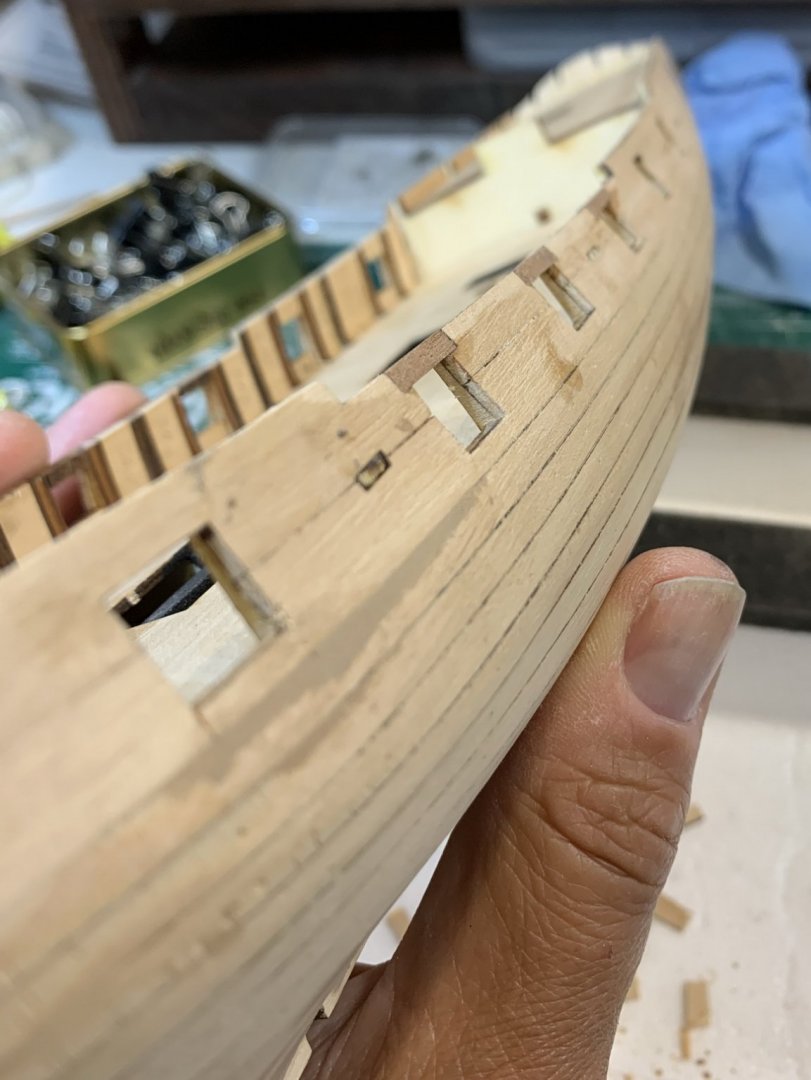
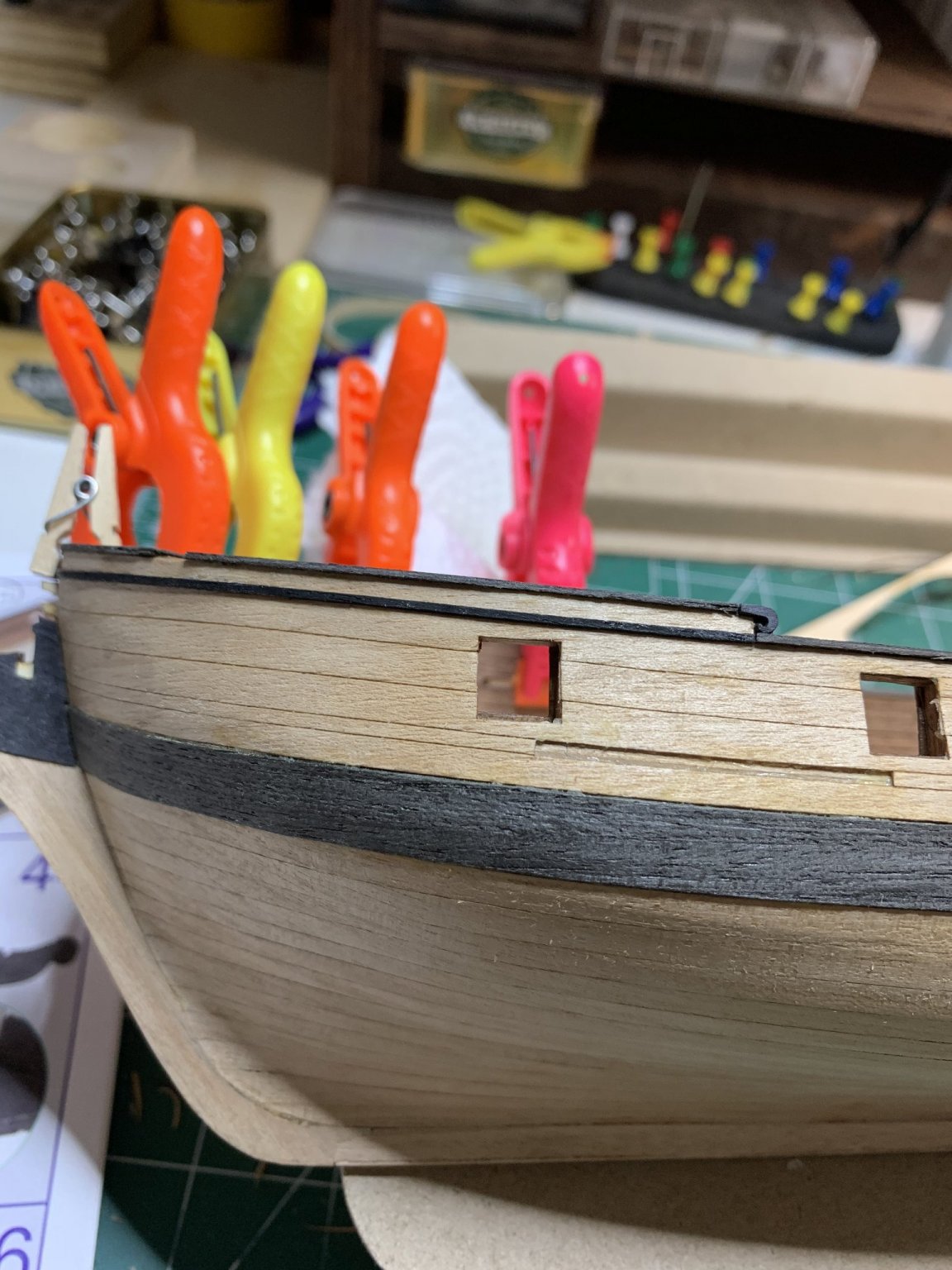
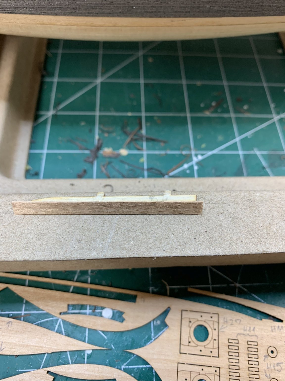
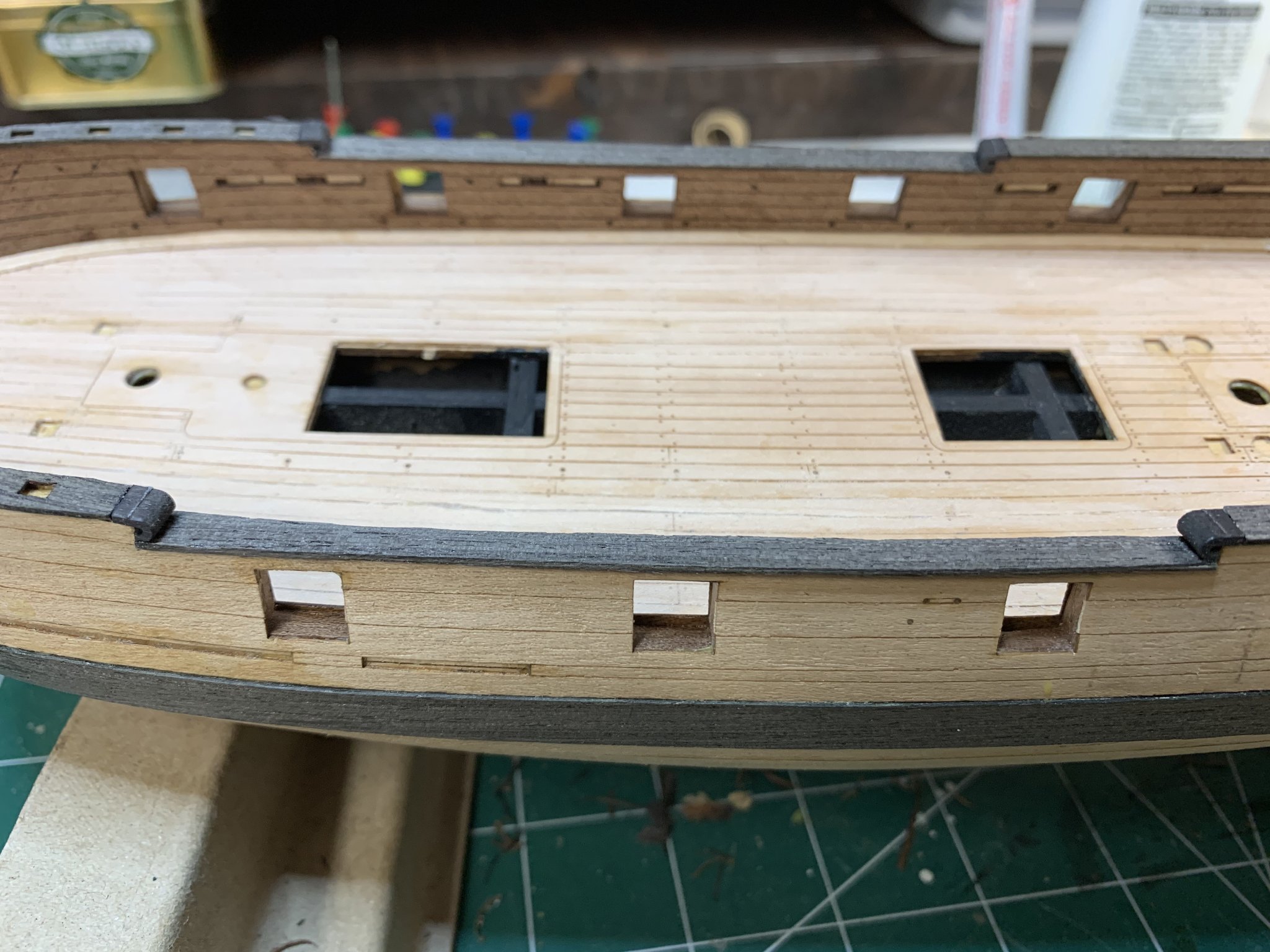
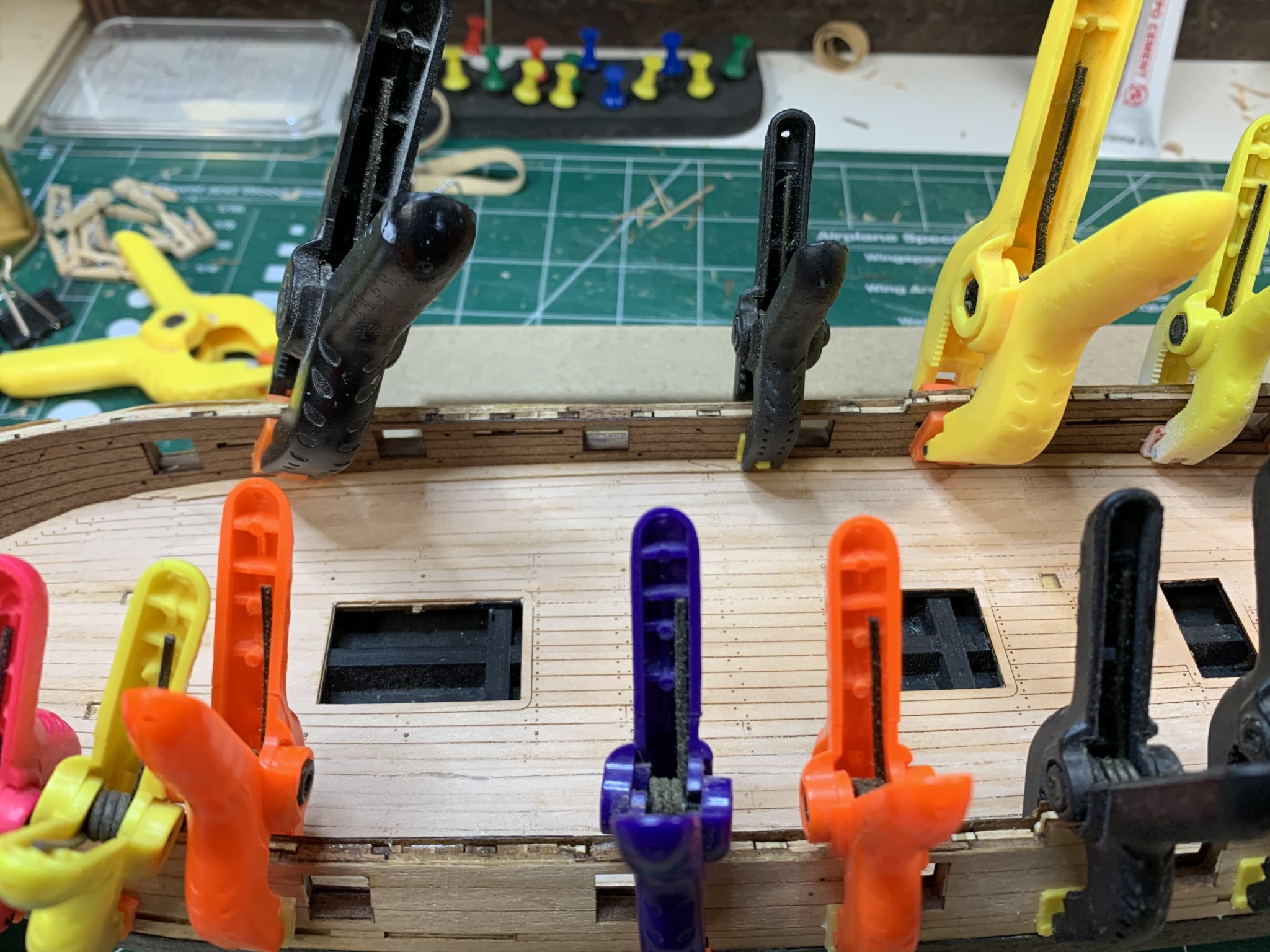
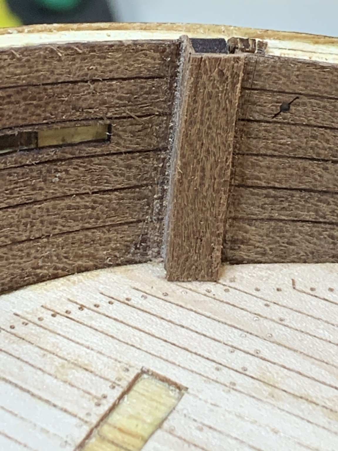
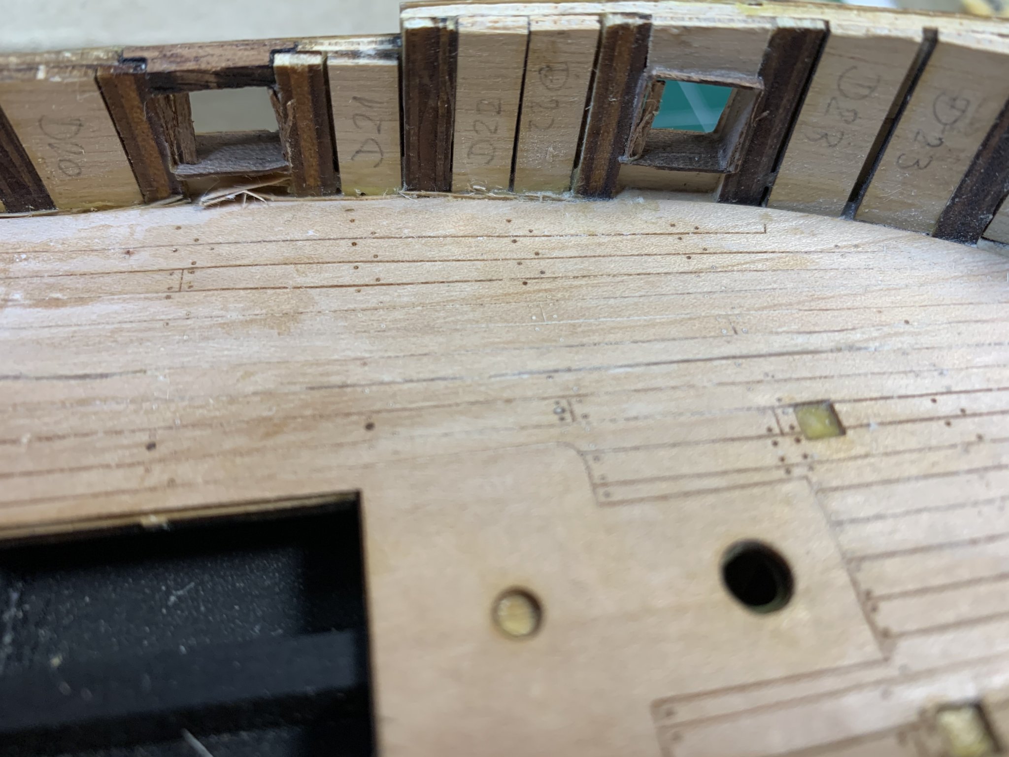
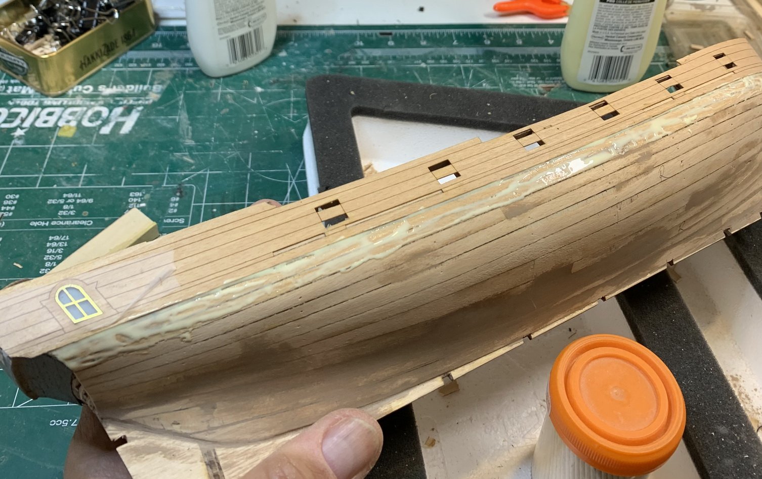
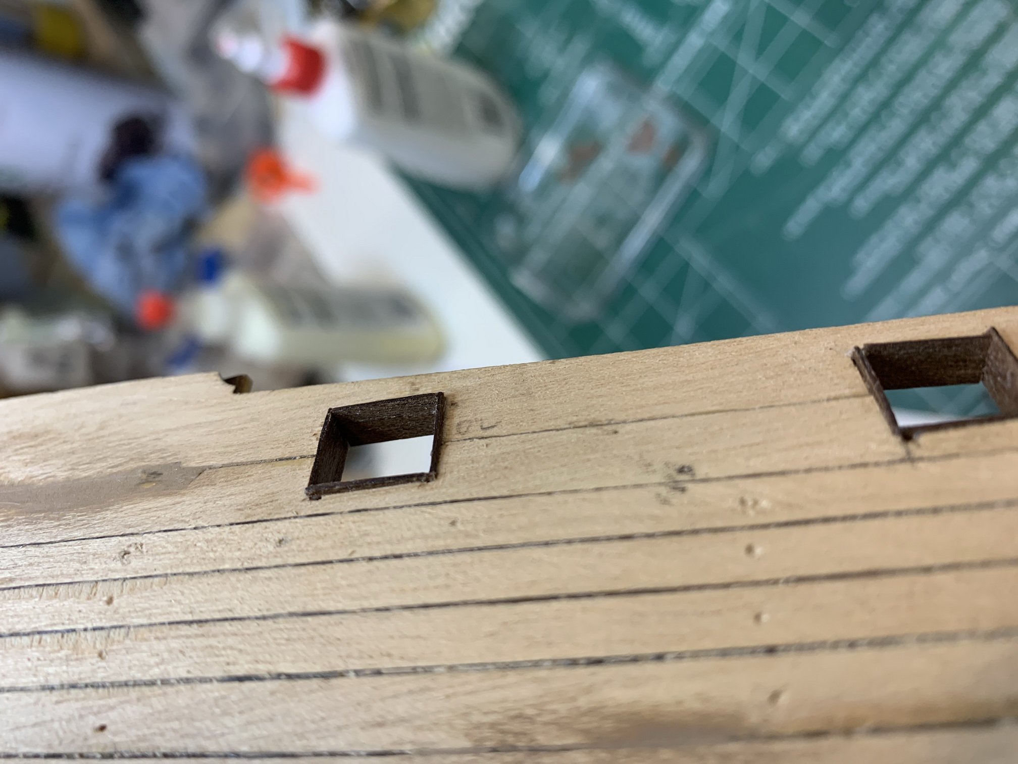
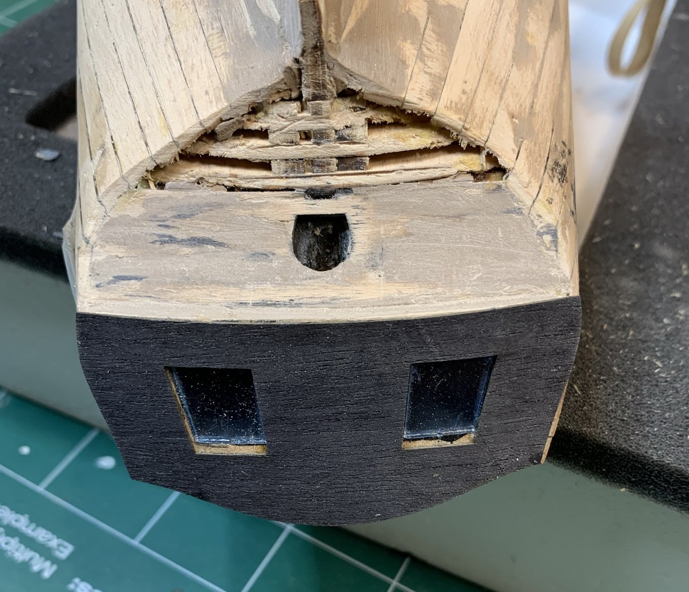
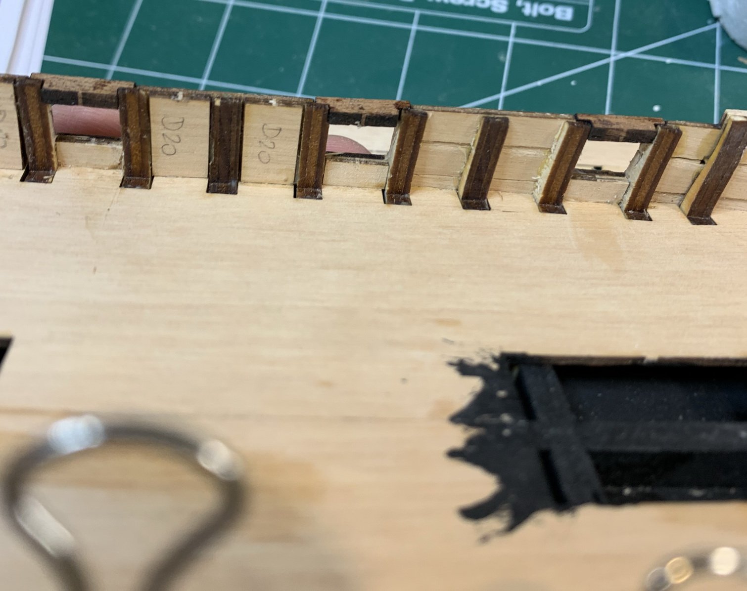
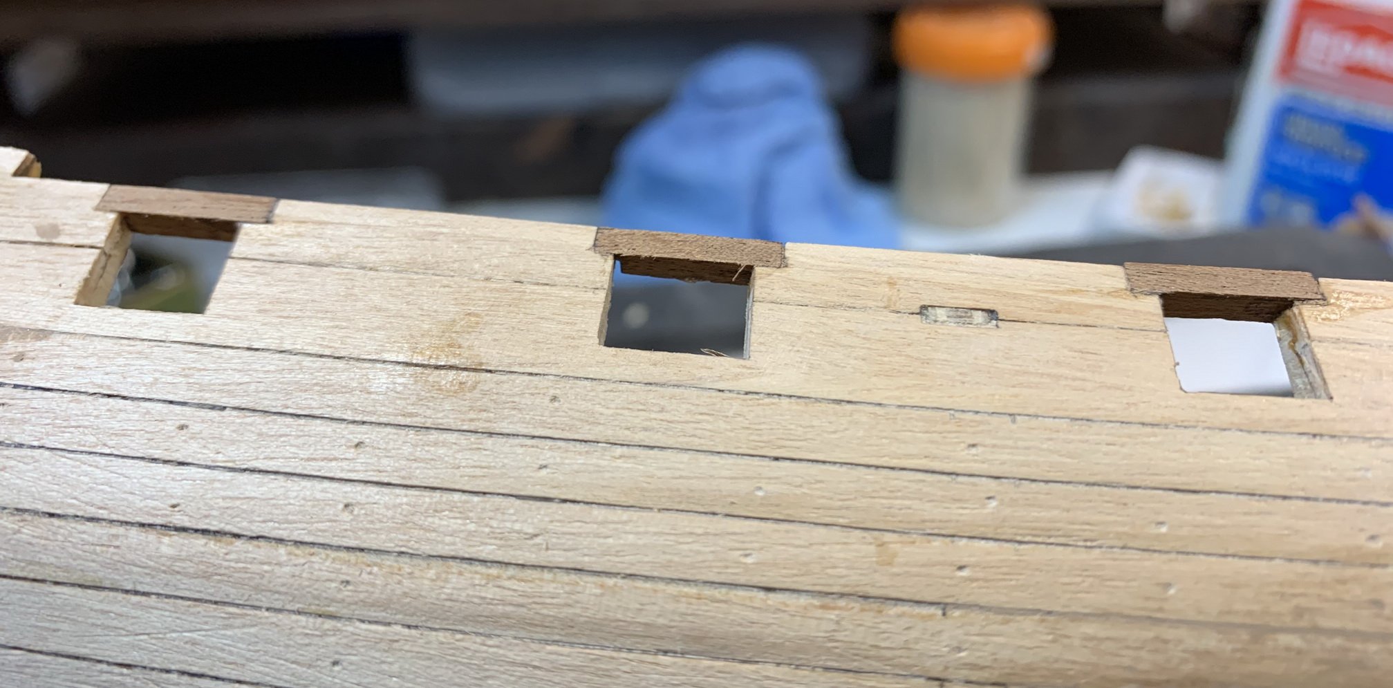
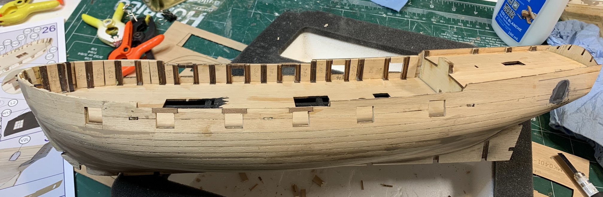
Work on the hull continues; i have cut cannon openings, installed, not sure what term to use, a piece of darker wood on the top of gun openings... it is needed just for 6 cannons
Next i have installed planks that fits between the bulkheads.. They are precut and very small amount of sanding is needed.

But we do need to add a small piece of wood to make sure that bottom part of that "plank" fits with bottom end of the bulkhead..

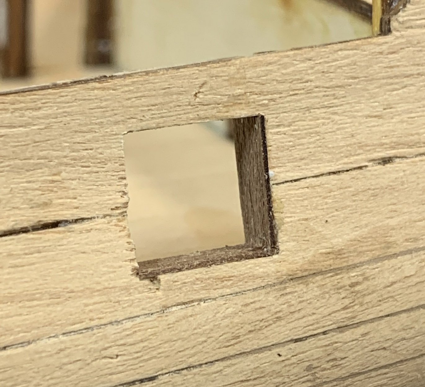
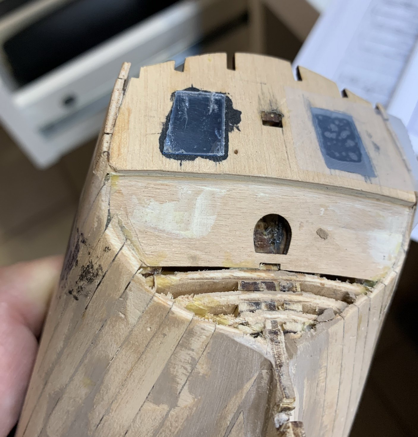
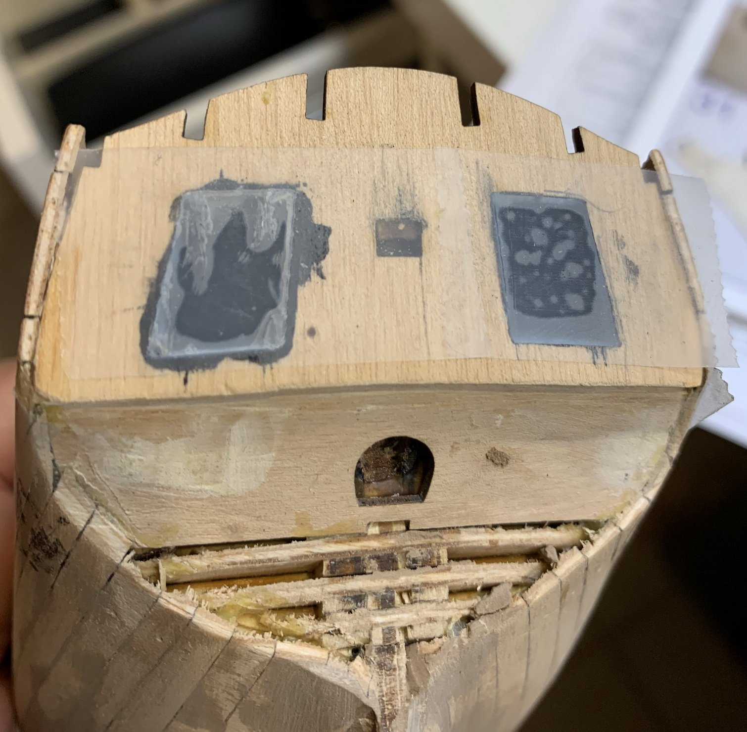
Then i started to make a room for a window; kit comes with plexiglass windows, precut very precisely that the only thing to do is to push them into opening. A bit of force is required but this will make sure they will not get lost in the process. The window opening was painted in black, window pushed in and protected by a piece of scotch tape. There is also a plastic folia on the window so there is no need to add a scotch tape... but... just to remember to remove it before continue with window work..

Sanding is next step...
and this is all for today...
Happy modelling.
- Wahka_est, GrandpaPhil, Richard44 and 2 others
-
5


Phoenix by Moreplovac - FINISHED - Master Korabel - 1/72 - Russian Brigantine
in - Kit build logs for subjects built from 1751 - 1800
Posted
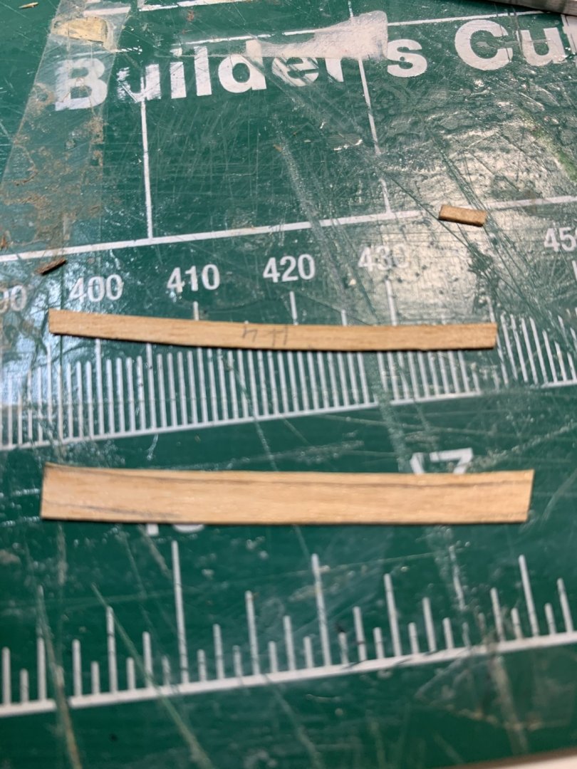
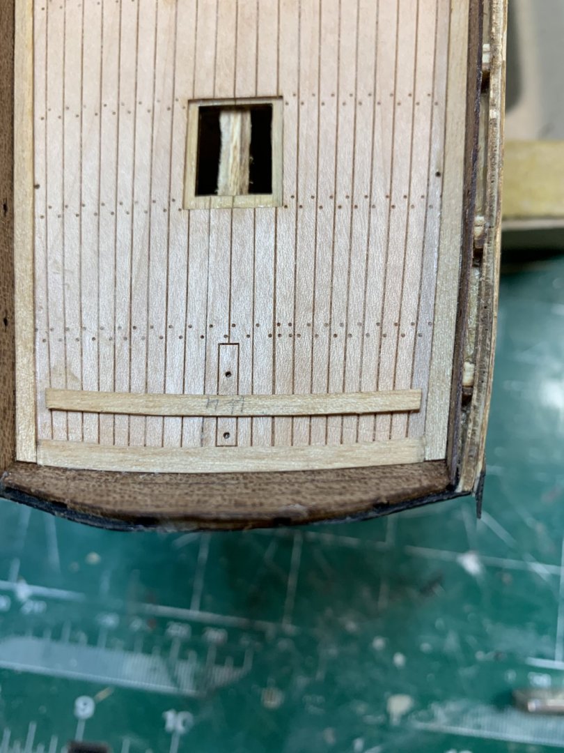
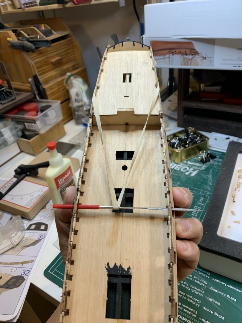
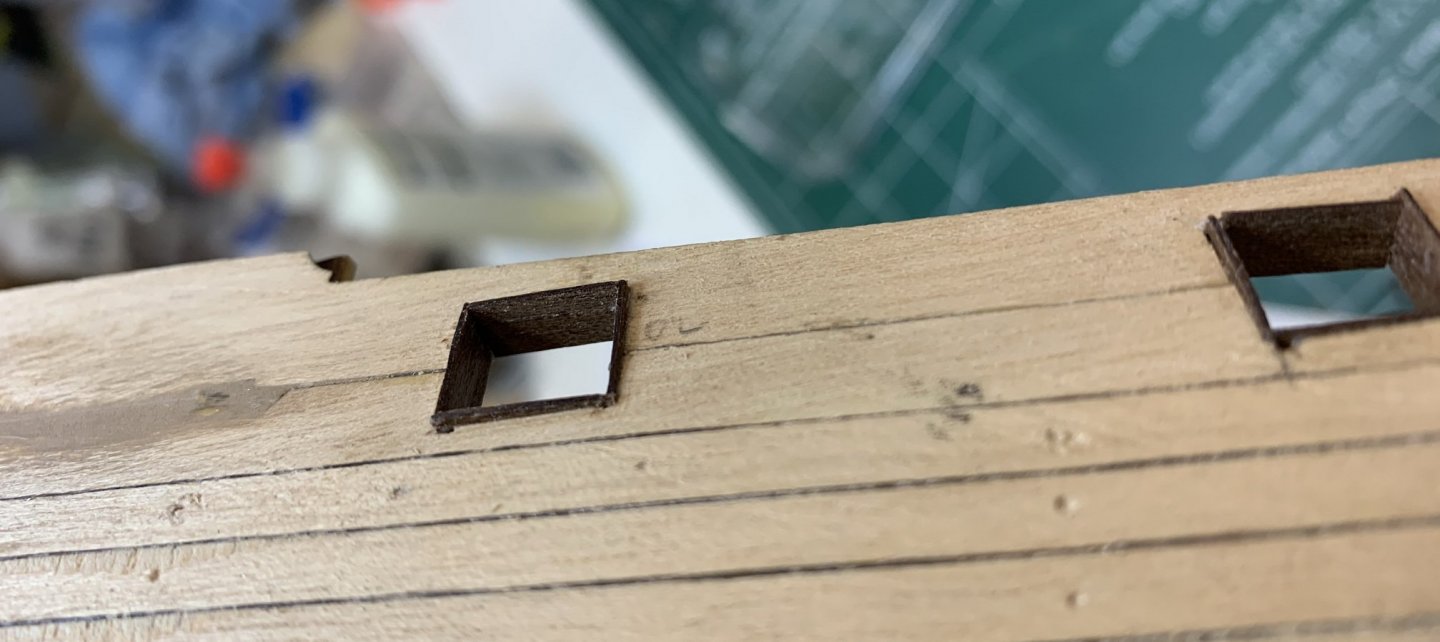
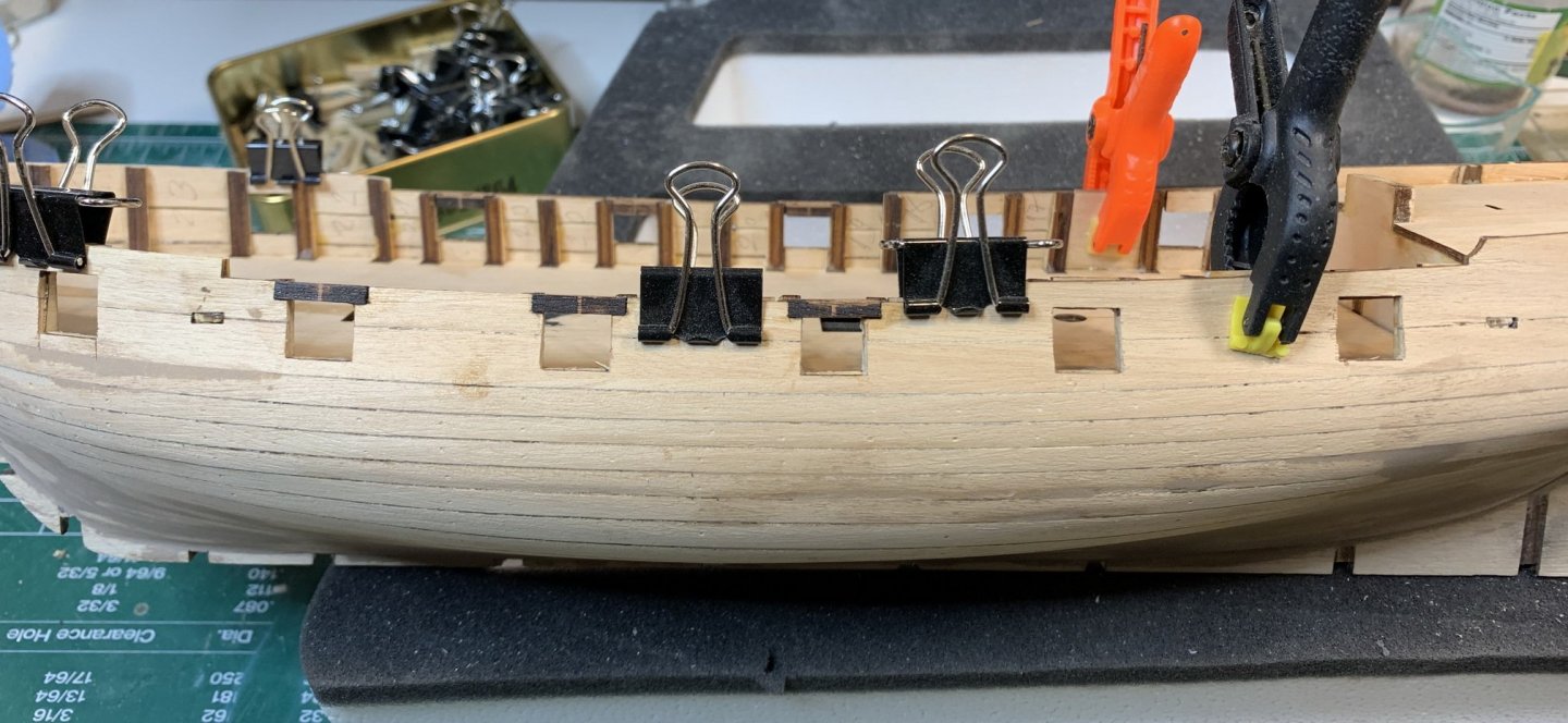
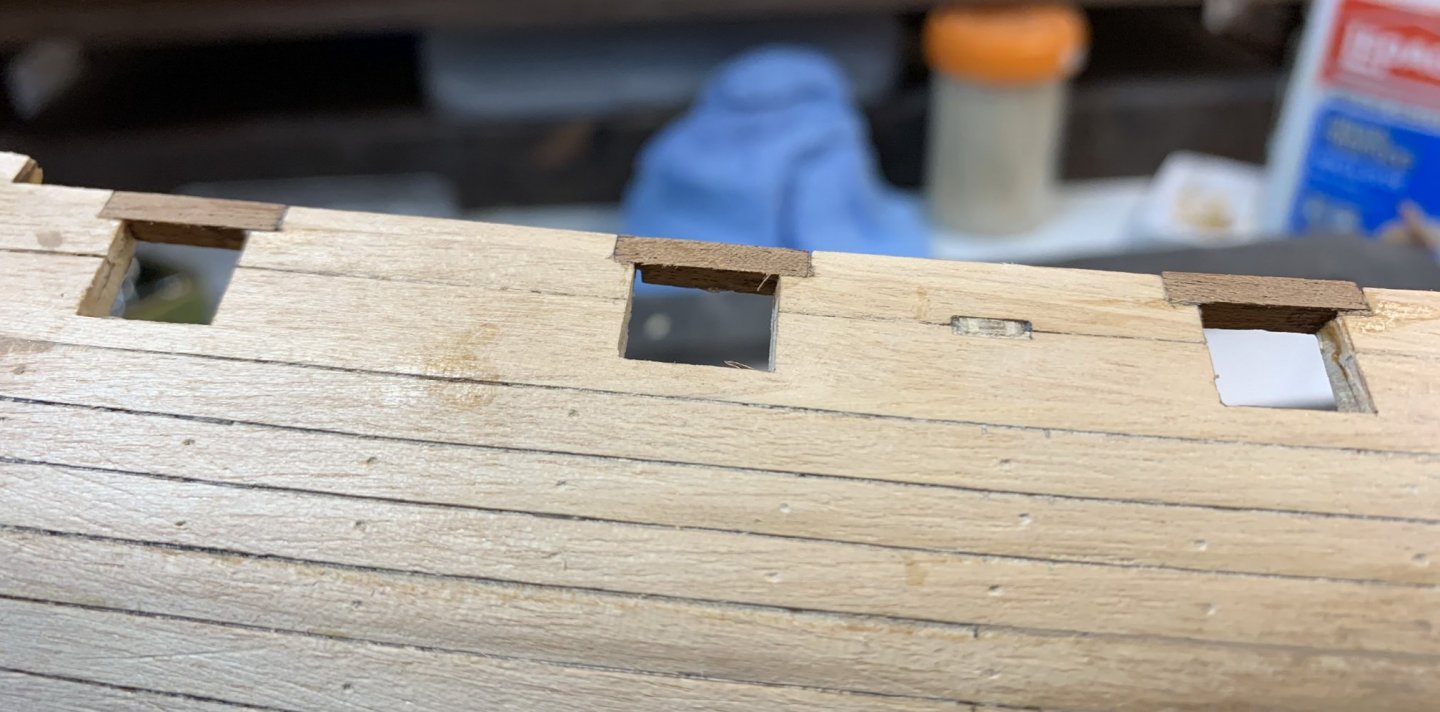
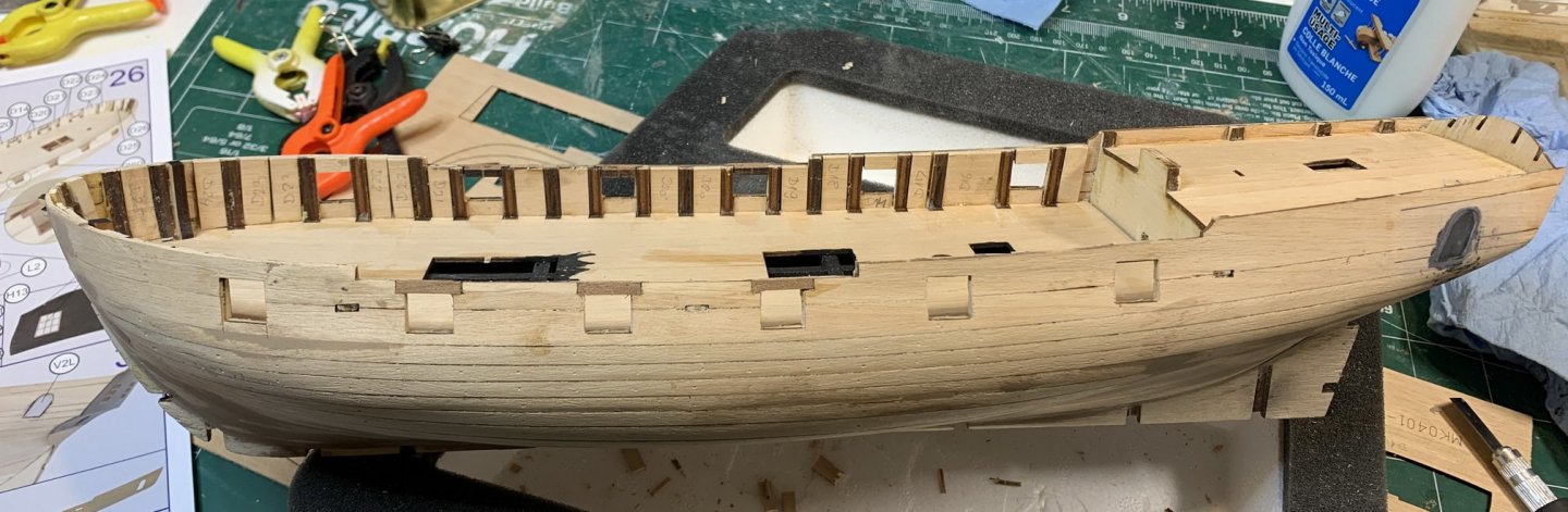
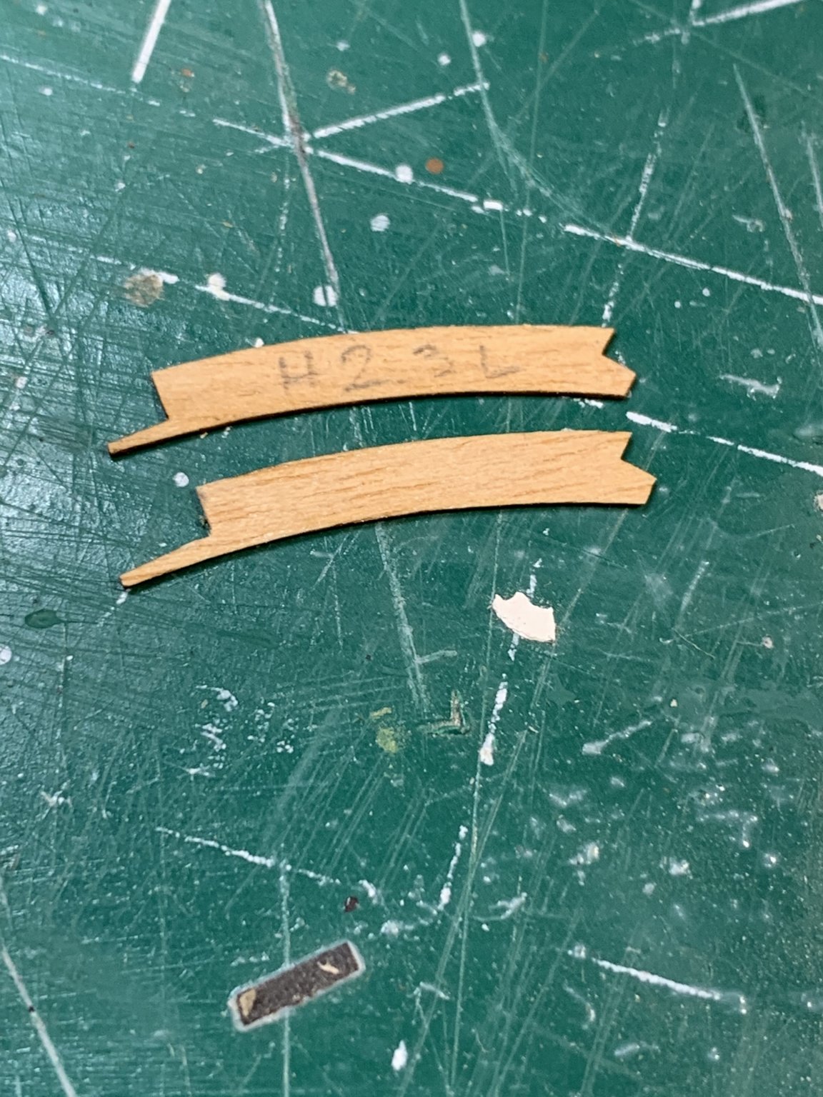
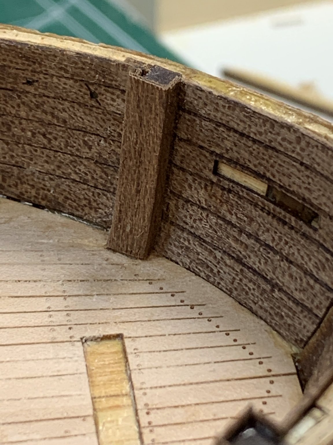
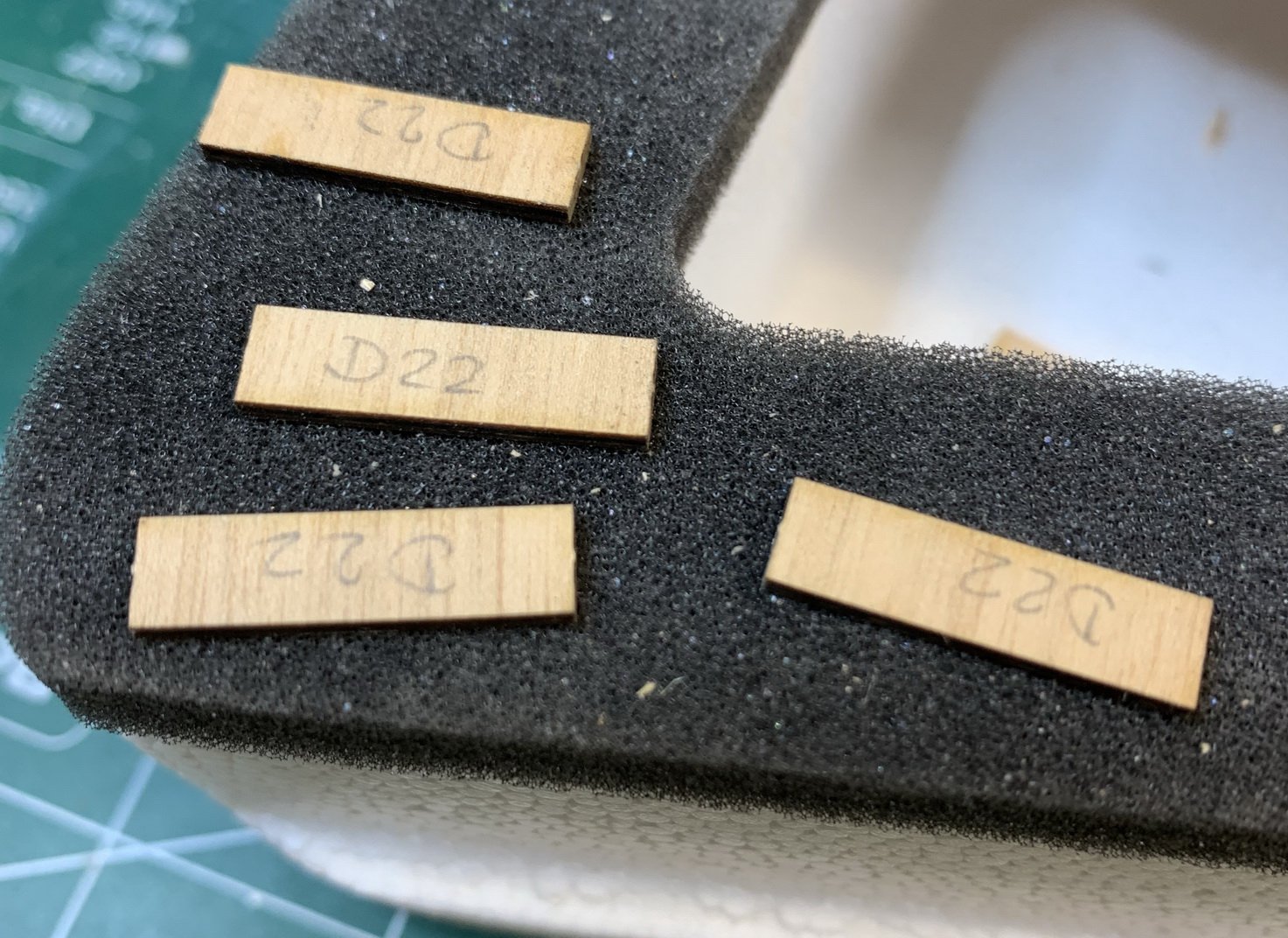
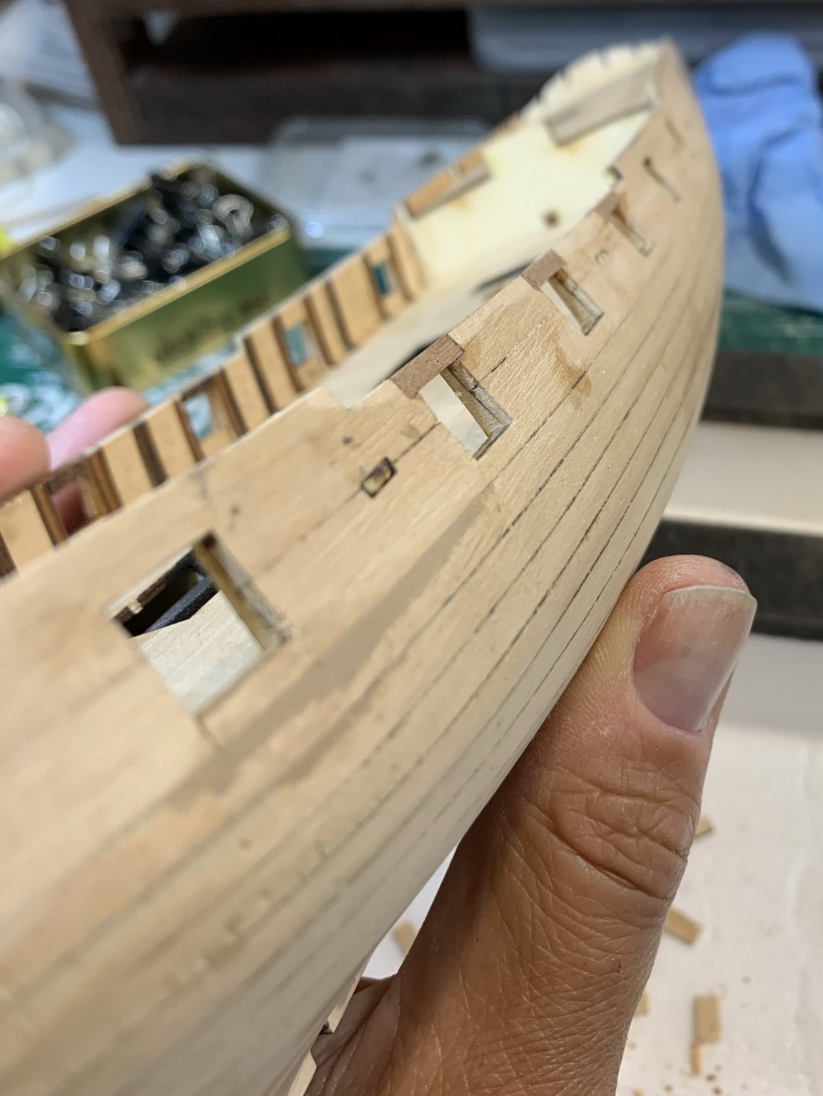
Work continues by installing jumbs around gun ports.. There are three wood pieces in the kit for this purpose but i would use a different one that is a bit more wider so it allow more precise sanding and fitting...
Lets start then...
Measuring, cutting with a guillotine, glue, sand...
A bit of a sanding after all...
Happy modelling...