

moreplovac
-
Posts
709 -
Joined
-
Last visited
Content Type
Profiles
Forums
Gallery
Events
Posts posted by moreplovac
-
-
On 8/22/2018 at 2:41 AM, lmagna said:
You are right I can see them now.
Great work on your swivel cannon mounts. Looks like you are making great progress!
Thank you Lou.
-
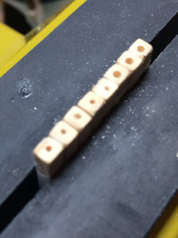
The gunstocks are next. The rest of gunstockes were build, 10 in total.
Cut them to the size as per plan; on the bottom i did a small angled cut and shaped each gunstock as per plan.
Each gunstock received a small hole filled with wood filler to simulate trunnel.
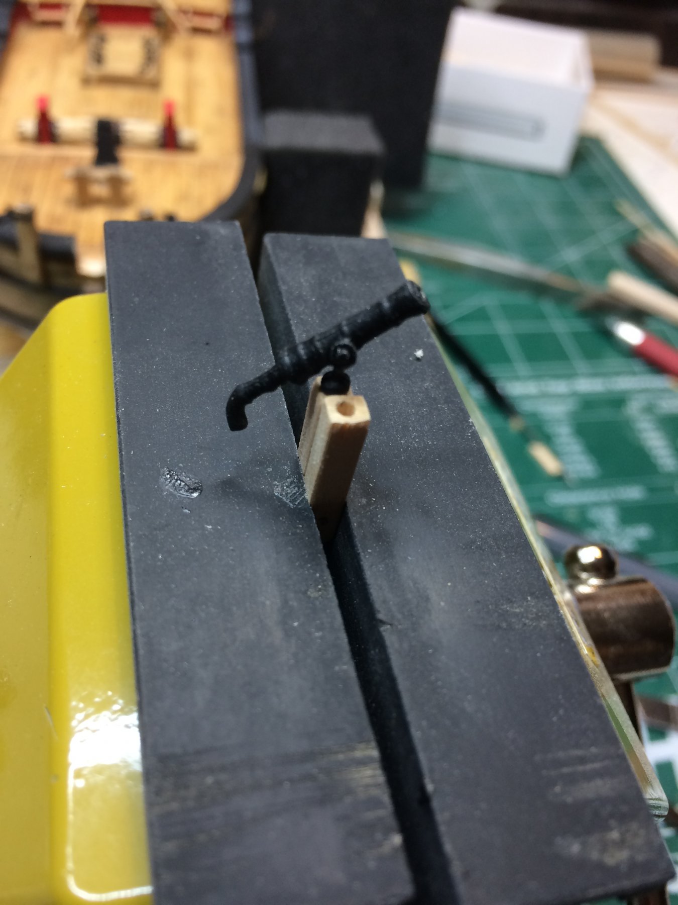
The hole for a swivel gun was drilled on each gunstock as well as on two already mounted on the ship. That was a scary part but managed to have it done... To drill holes i put all gunstock on the piece of scotch tape and get them all into vise. Then marked approximate center of the gunstock with pencil, drilled a small pilot hole with hand-drill and with assistance of proxxon rotary tool made first 0.5mm hole than widen it with 1.3mm bit..
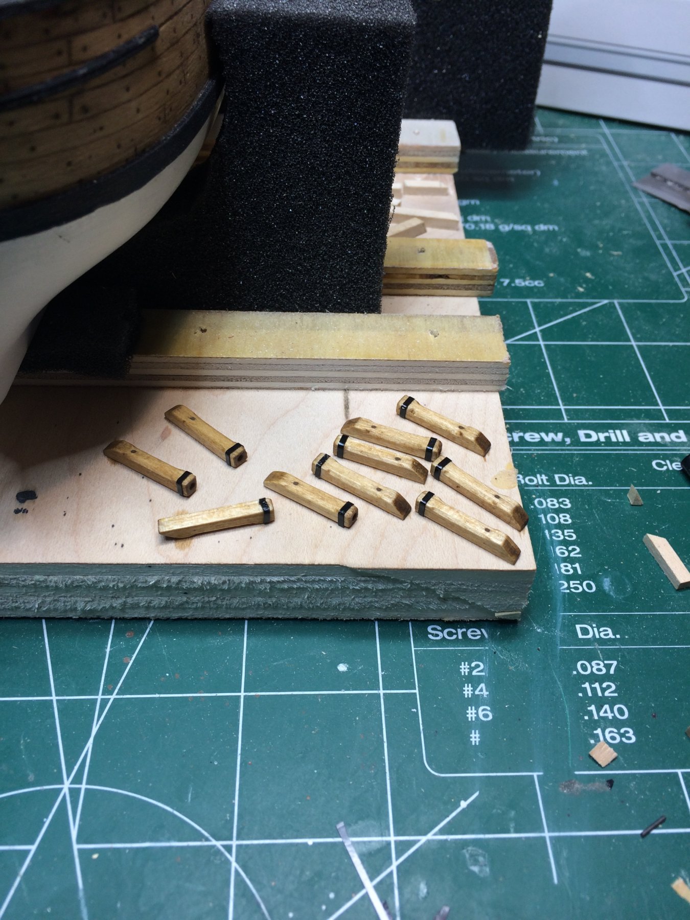
All done and ready for electric tape to simulate iron band..
1mm electric tape strip was applied to each gunstock, the drop of cyano glue added additional strength to tape. That tape is fairly stretchable and if stretched to much it will shrink afterwards leaving a gap between two strip ends.
Each gunstock received a quick bath in wood stain.... and here they are, ready for assembly.... but that is something for tomorrow..

Fitting testing...
Happy modeling..
- lmagna and GrandpaPhil
-
 2
2
-
1 hour ago, lmagna said:
Must have been a very poor day for posting as well. Even the picture didn't work for me!

I dont think it is you, i believe the way i inserted picture was wrong.. It should be OK now.
-
-
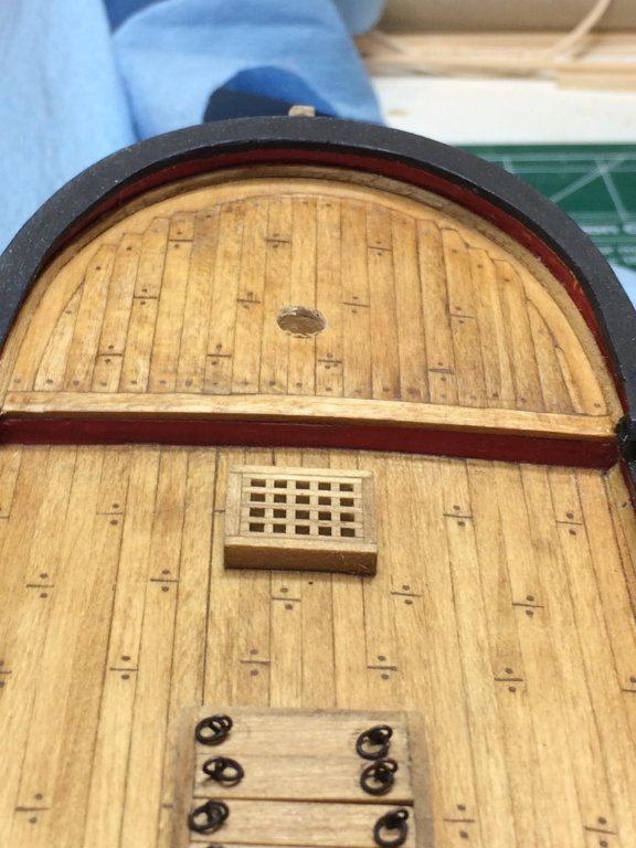
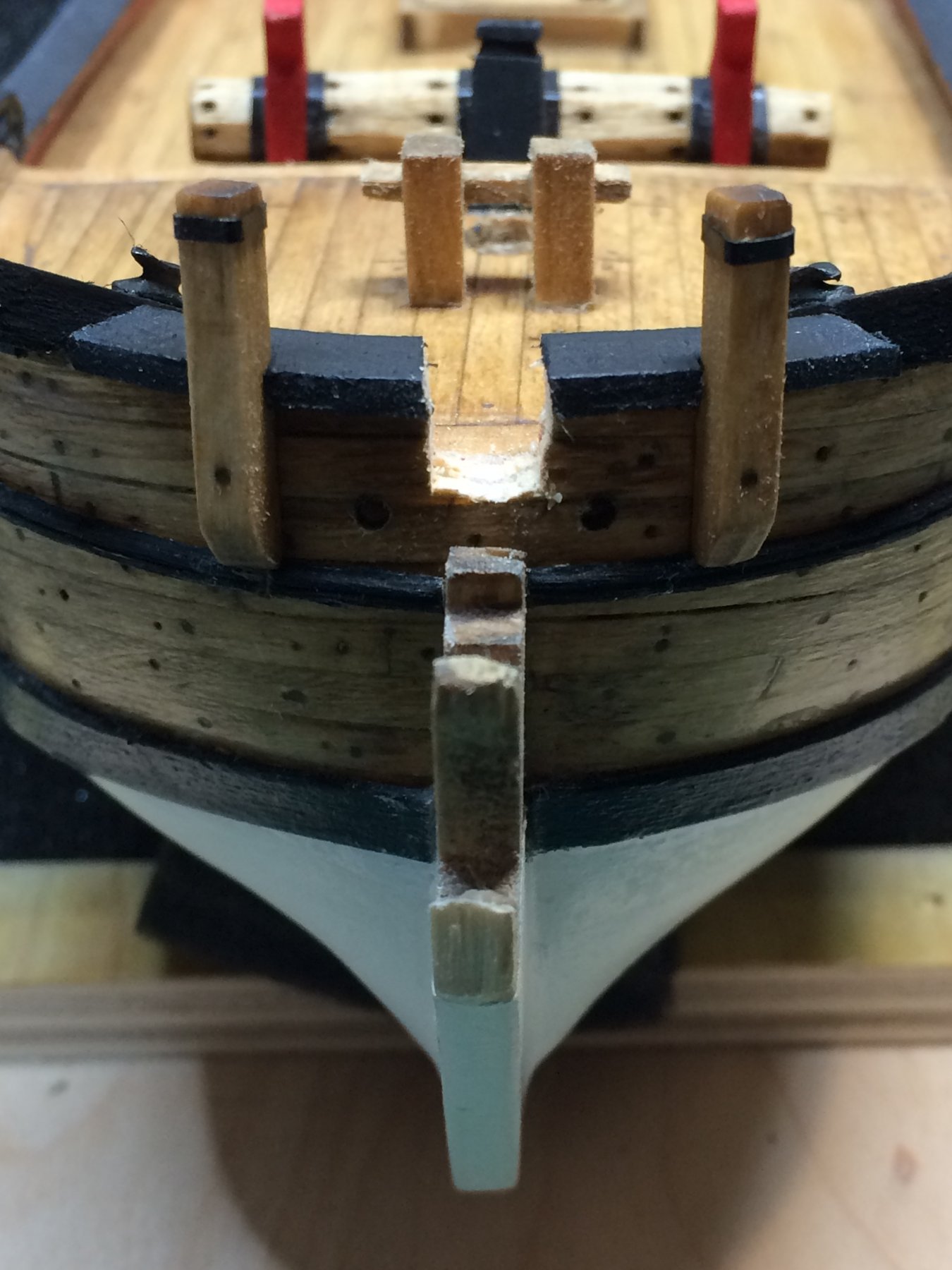
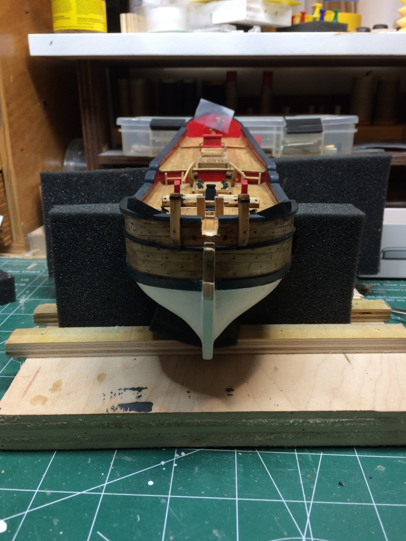
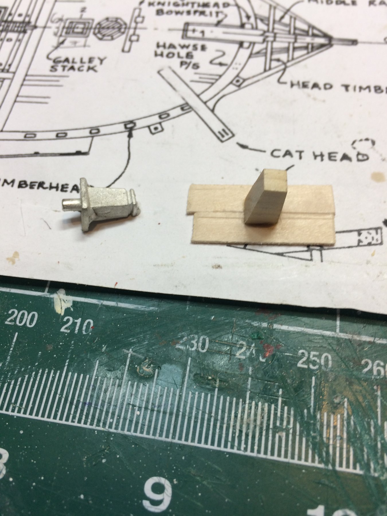
Following Practicum, i started adding details on cap rail area... First i cut a notch for the bowsprit with a hobby saw and using files the opening was rounded but not completely... The main tweaking will happen at the time of bowsprit installation.
Despite the fact that i do follow practicum, i missed one part. The steam was to short. Good part is it is no just me. Following Chuck's suggestion i will add a piece of wood to lengthen the steam to correct dimensions. This is task for tomorrow...
Now looking at the pictures it looks that notch is a bit wider that needed. Something to deal with at the time of actual bowsprit installation. Bit more work to do. As Chuck mentioned, mistakes do happen...

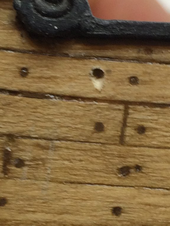
Then i worked on hawse holes; marked, drilled and shaped with a file.
Gunstocks were made next. Cut a piece of wood, a tin strip of electric tape was simulating iron band but i forgot to drill a hole on the top, for a swivel gun. It will be a bit hard to do it after but... The other gunstocks will be done with a hole before mounting. Also i simulated trunnels by drilling a small hole and fill it up with wood putty. A nice little detail. Before mounting, i dip both gunstocks into stain, leave it for 15 sec and dry it out with paper towel.

The notch for gunstock was cut in the cap rail, shape corrected with a file and before mounting gunstocks, i run a layer of flat black color on cap rail area where gunstocks will be mounted. This is to prevent messing gunstocks with black color since i am planing to lay one more layer of black color to cap rail before putting a protective layer of varnish.
Tomorrow few more gunstocks and will work on fixing short steam....
Happy modeling.
-
Today i started with painting catheads in flat black and mounting them on the ship.

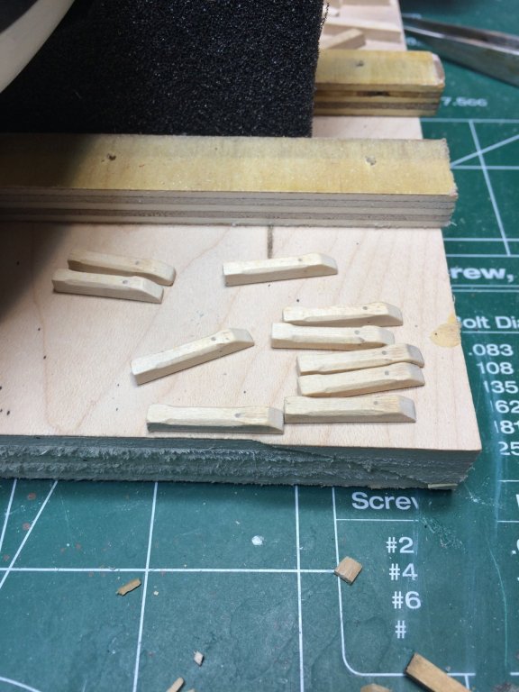
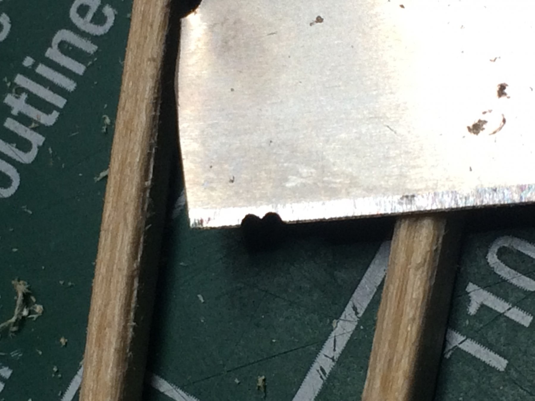
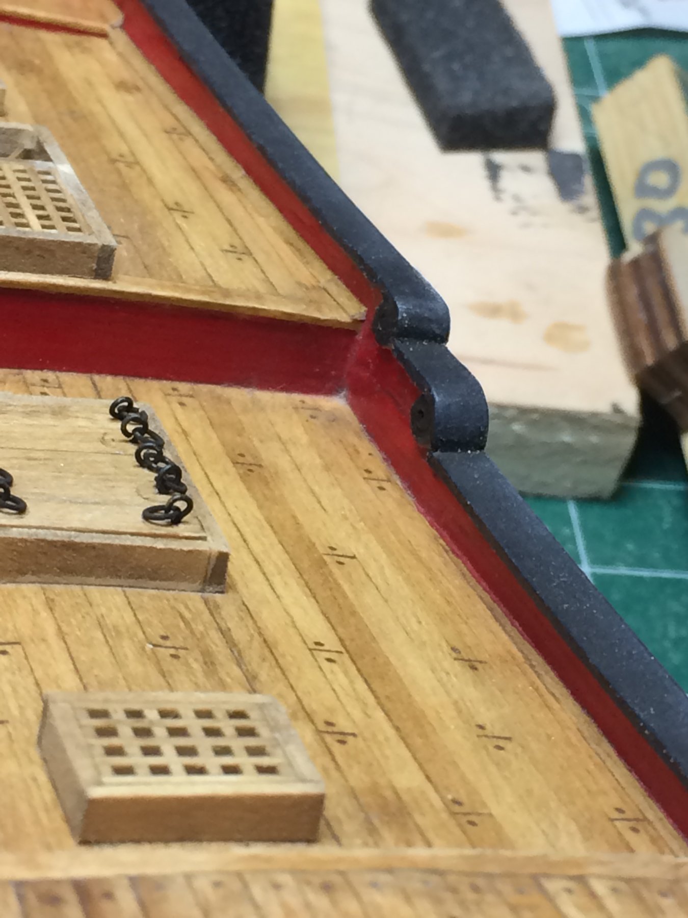
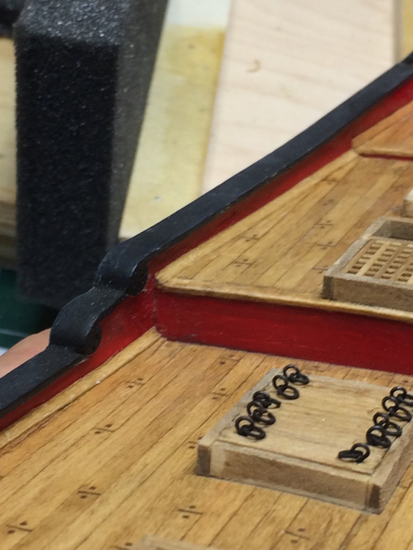
Next part was interesting one. Molding. I never worked with molding in such a tiny scale. First making scraper that will be used to shape molding and then actually make few. Following Chuck' practicum about the shape of molding i started making a scraper. After few unsuccessful attempts, i made one out of a razor blade. Using carbon file i made a groves that will assist in scraping the correct shape.
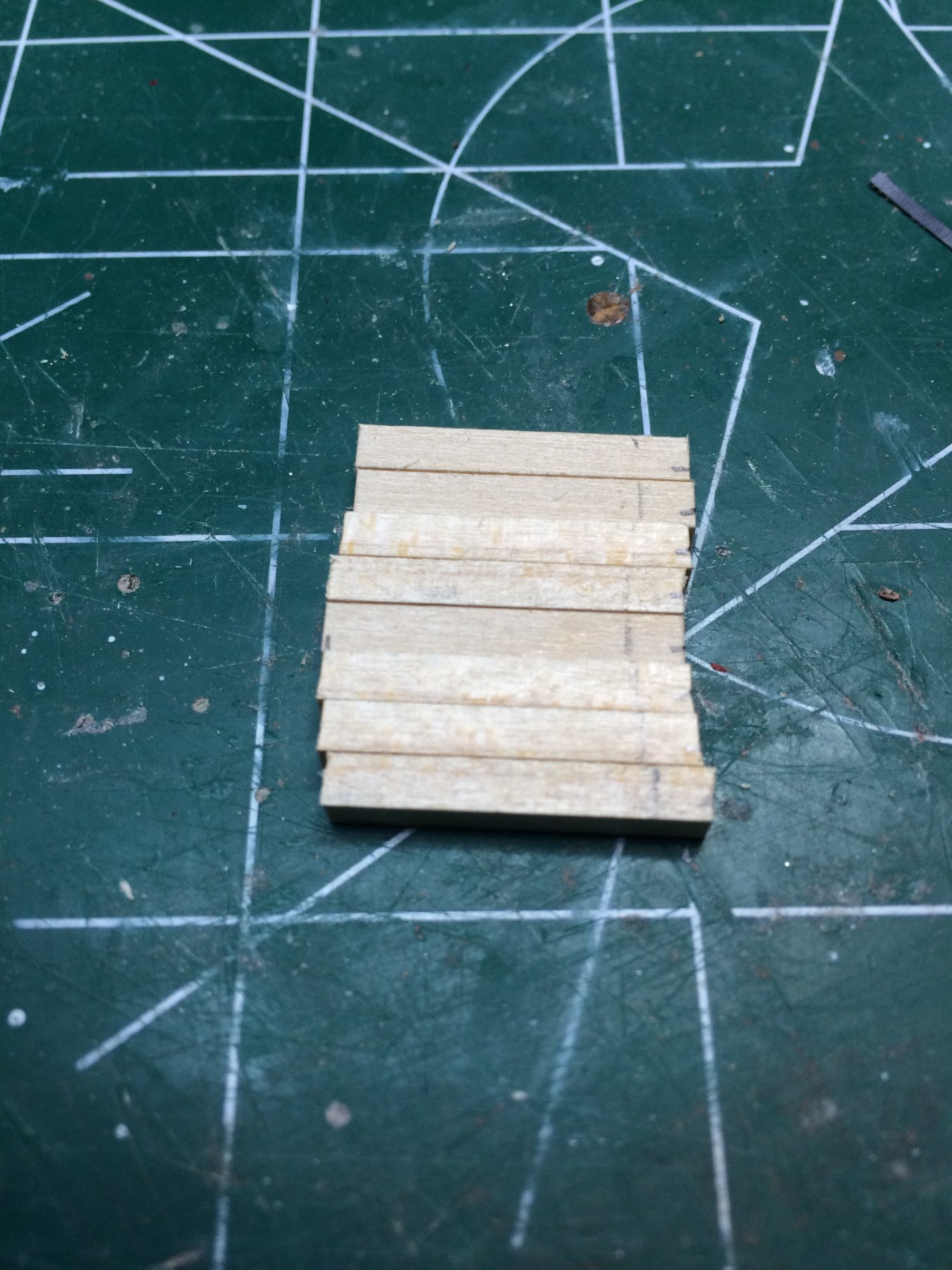
Cut few pieces of boxwood strips in 2x2mm, i started scraping the molding. Fortunately i had plenty of boxwood strips in this dimension since several attempts ended up in broken or uneven moldings...
Finally get few usable moldings that will be installed on the ship.
Paint them in flat black and assembled to the ship. These dudes are tiny for my over-sized fingers... But luckily there are tweezers...
First i marked the locations where they will be mounted...

Then after some time...
The stern still requires badges to be installed; after that remainder of moldings will be glued.
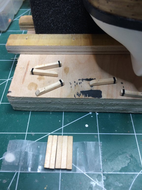
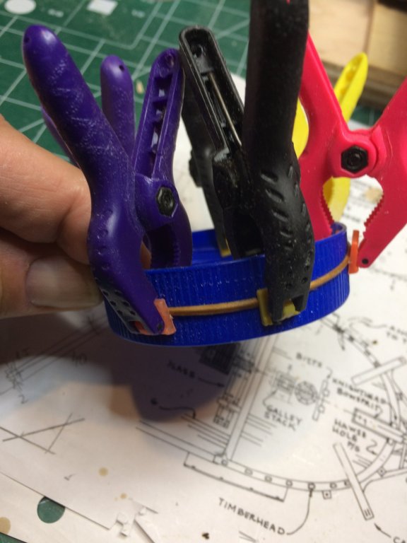
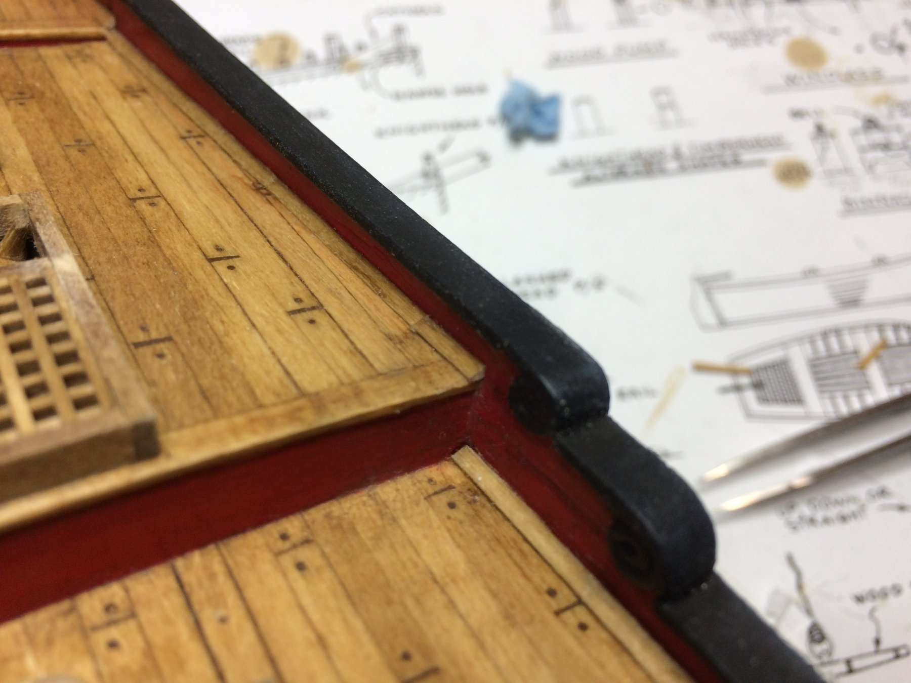
Bow moldings have to be bended to follow the bow shape; 10 minutes in water bath and slowly bend them over a electric tape...
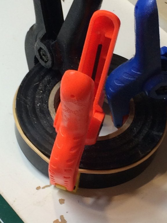
Making sure not to squeeze molding and damage the shape i used small clamps just to keep molding in shape..
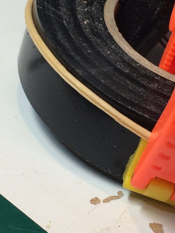
No rush to mount then; moldings will be left overnight to dry and tomorrow a coat of flat black paint and assembly..
After mounting the moldings and doing some touch ups on the rudder i will give it a nice layer of varnish to protect the whole model.
Happy modeling..
-
-
Catheads are on today's menu.. this sounded very weird..
Took a measurements from the plan, and cut the basswood strips to length. Shaped them based on the plan and Chuck' practicum, made cutouts to help seat the cathead in the position on the bulwarks. The scariest part was cutting the notch in cap rail for both catheads. Three times measuring = one cut...
After making the basic shape for the catheads, i drilled few holes, made a groove that will simulate sheave.
I decided to use cleats from the kit. Sanded and filed them nicely as they were fairly rough out of the box. Cleats were glued to top of the catheads, and two eye bolts were also mounted to the side of catheads. I used eye bolts that were supplied with a kit. Everything will be painted in black so did not spend time blackening eye bolts.
Catheads were painted in black and tomorrow will mount them permanently to the ship...
Happy modeling..
-
-
-
-
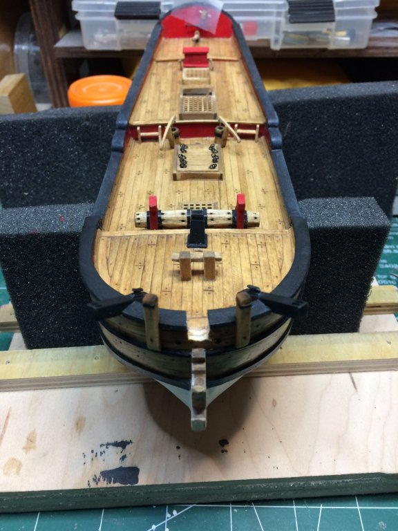
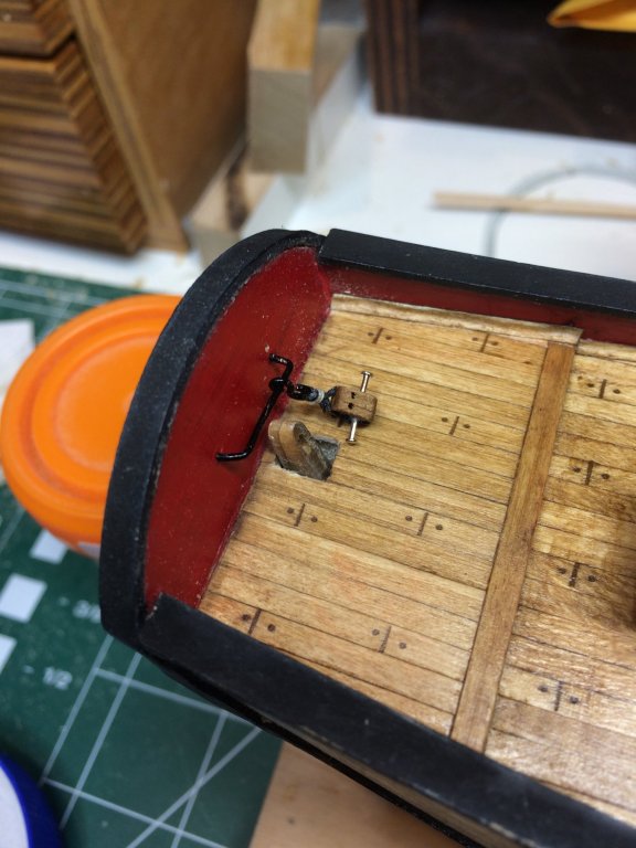
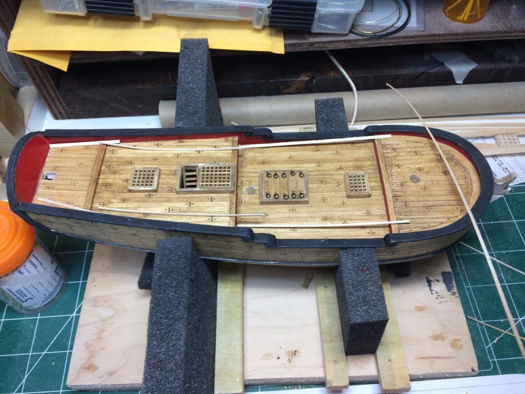
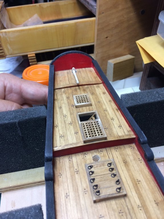
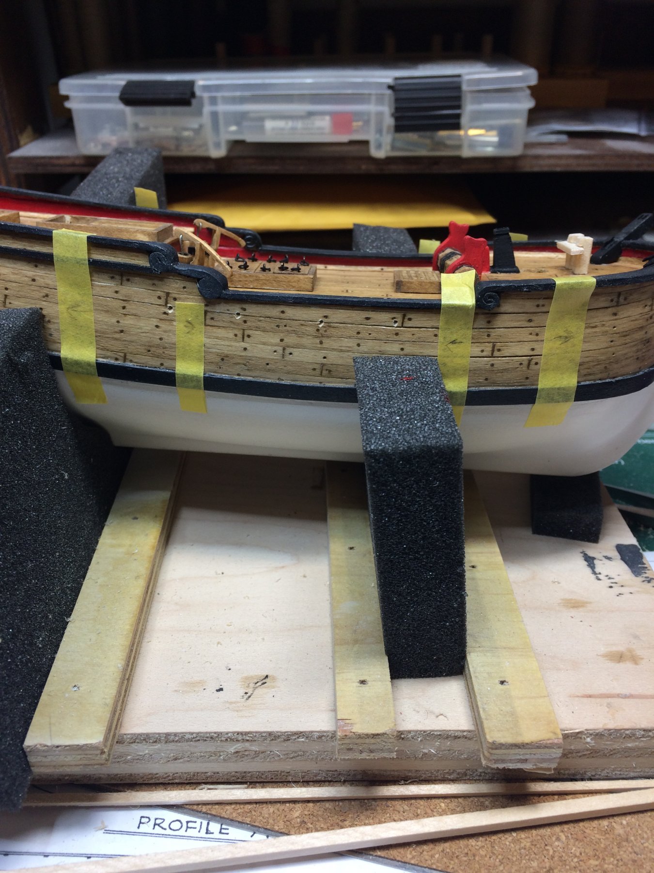
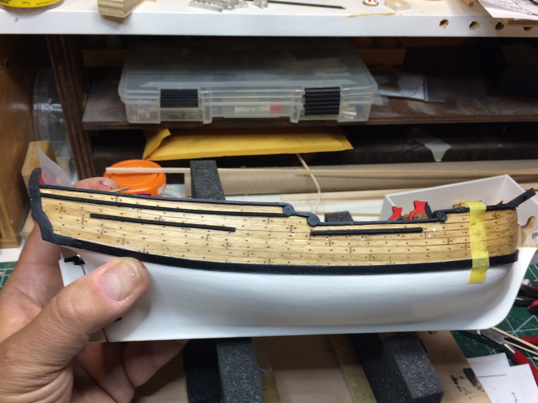
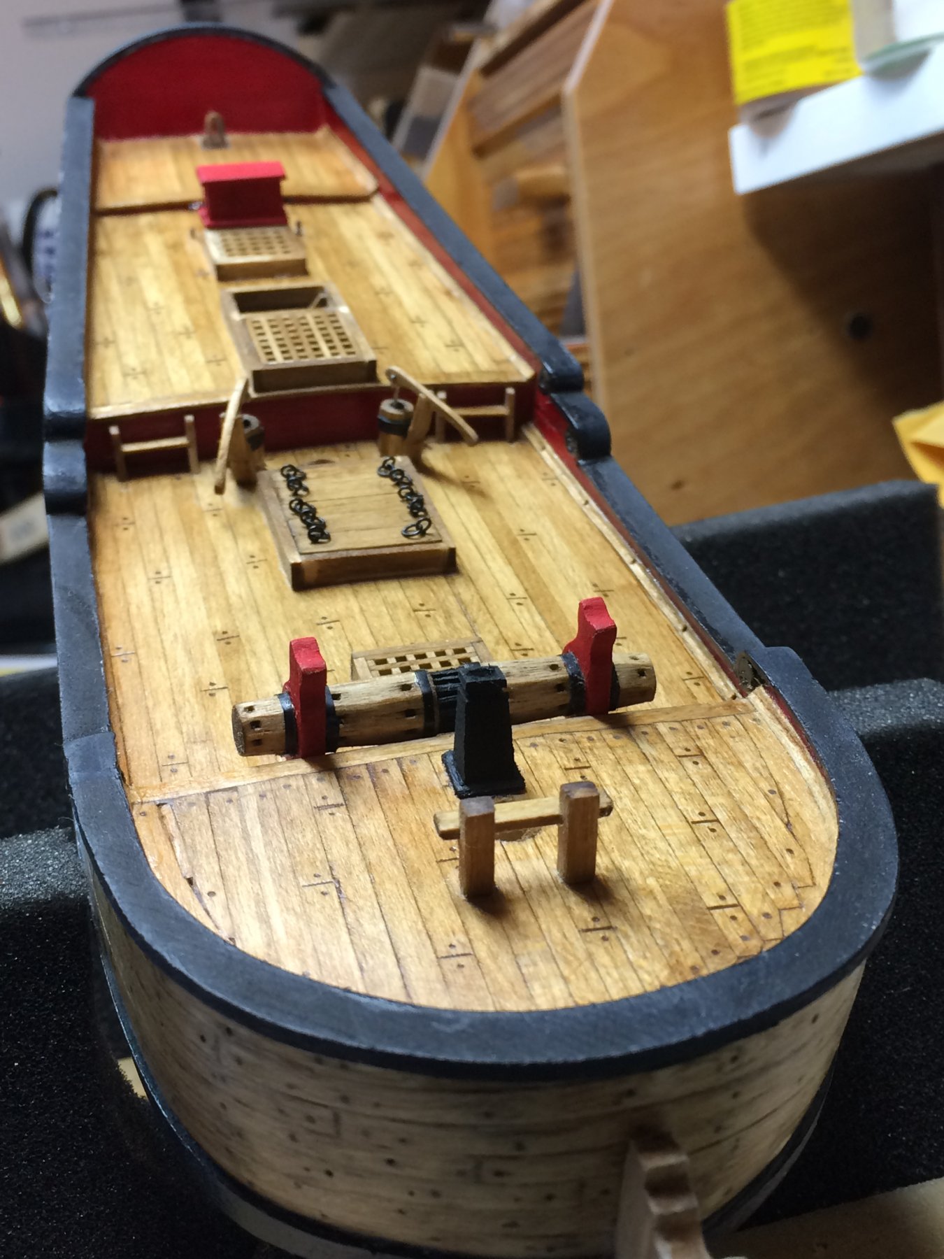
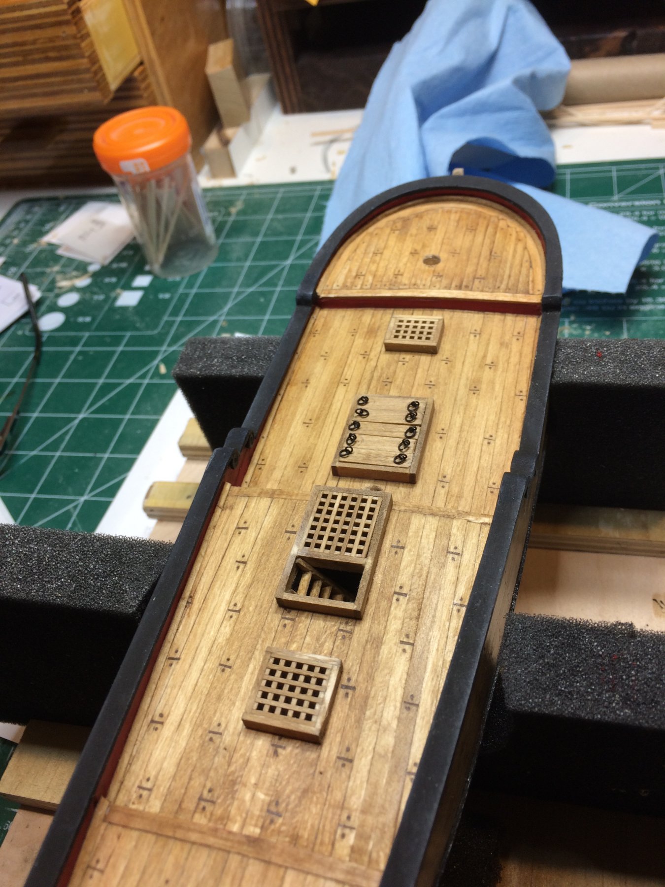
Then i mounted all (well not quite all, pawl for windlass has to be made and assembled) deck furniture i have build so far.
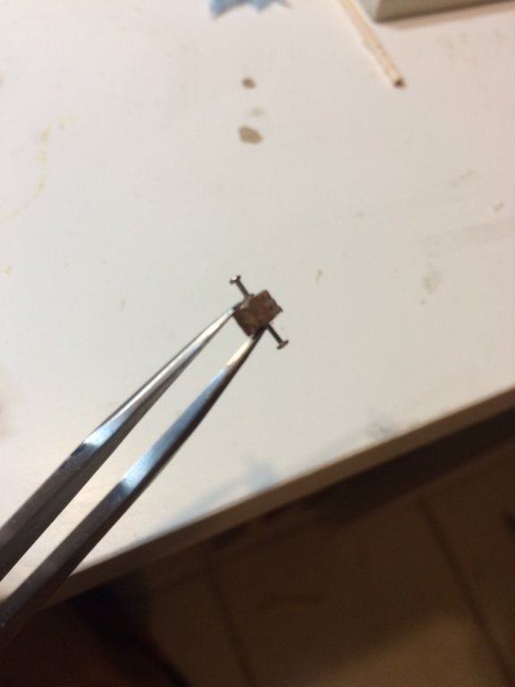
I put two small nails in windlass supports and marked place where windlass will sit. Then a hole was drilled for nails, carpenter' glue was used to glue it to the deck.
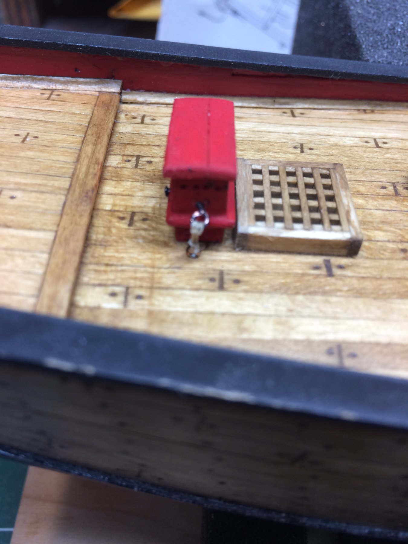
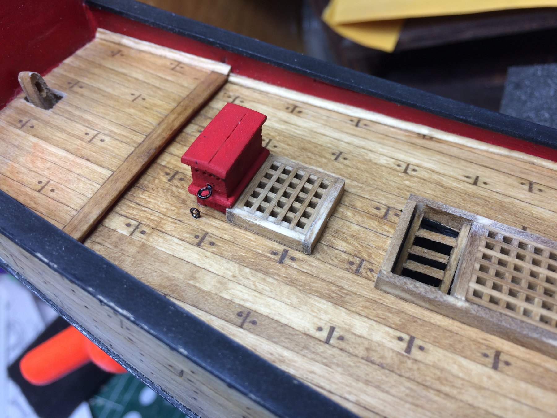
The galley stack was next, then binnacle with two hooks mounted on the deck...

Pumps and ladders...
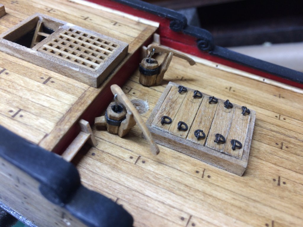
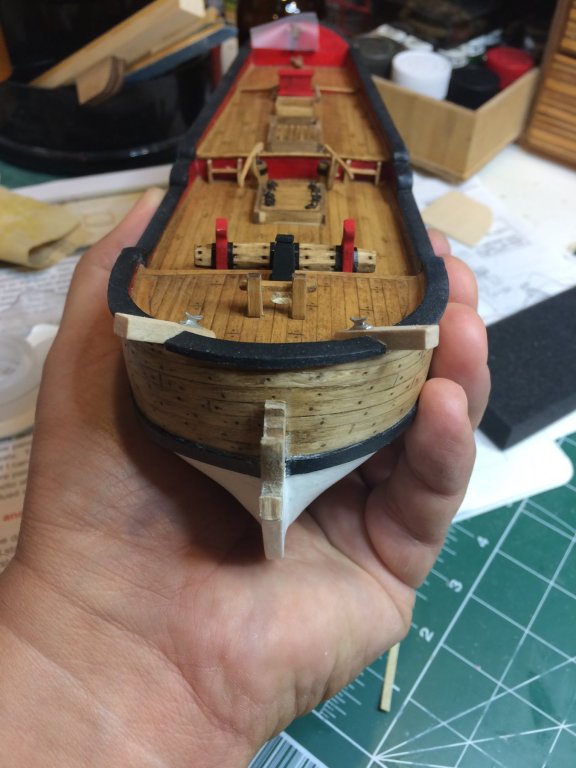
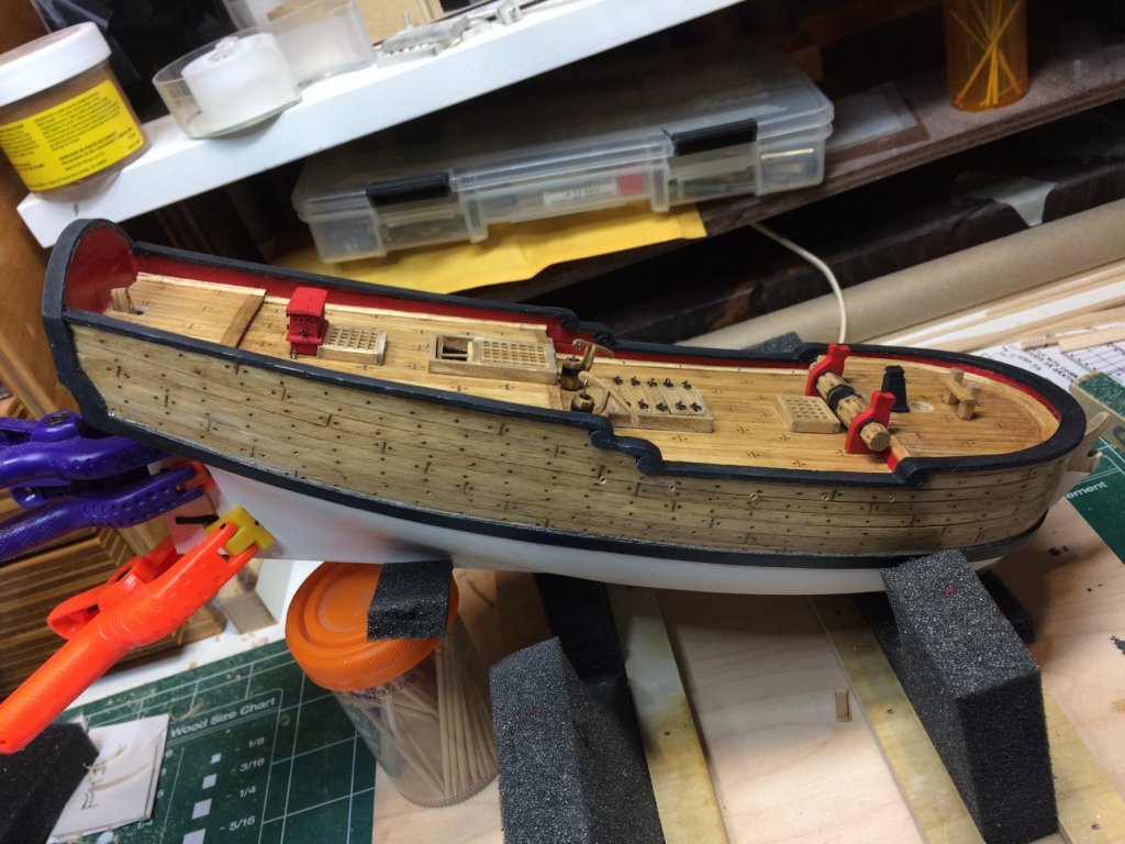
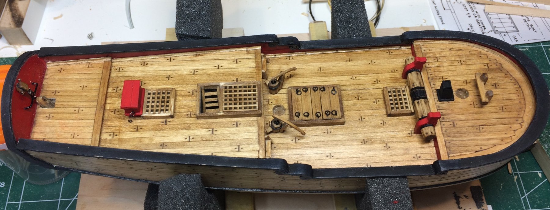
The view of the whole deck.

Then i give it another layer of stain to make all furniture the same (or similar) shade as the deck is...
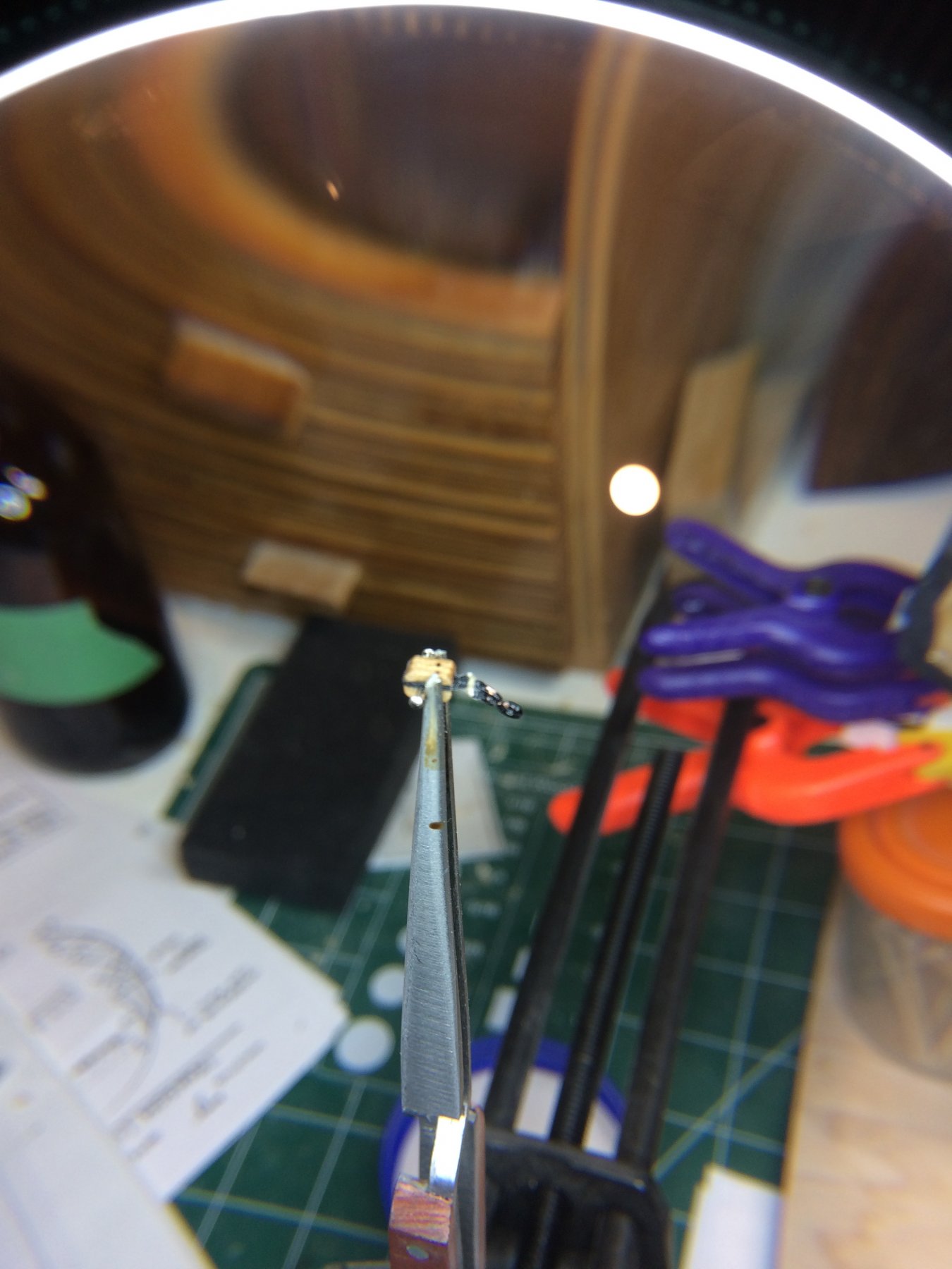
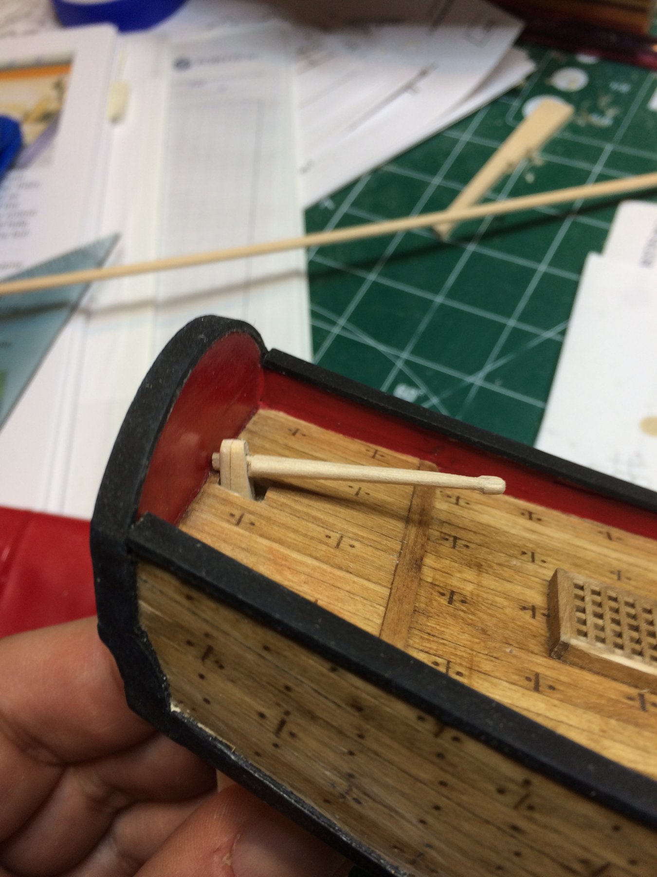
work on traveler rod was done but it appears to me that it should be a bit shorter in overall length. I will redo it sometimes today...
And through magnified glass...

Here is the whole deck for now..

Happy modeling.
- Sea Hoss, yvesvidal, GrandpaPhil and 3 others
-
6
-
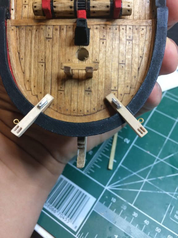
Rudder has been installed. I decided to leave pintles and gudgeons colored in black. Some touch-ups still have to be done..

-
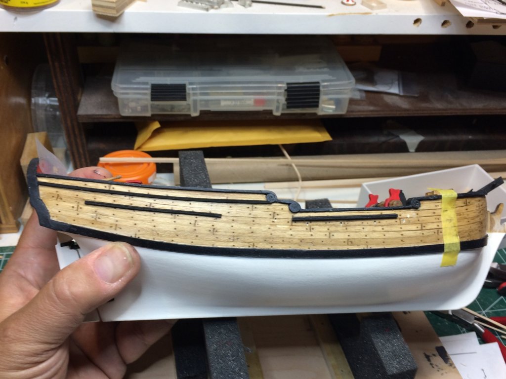
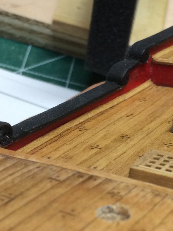
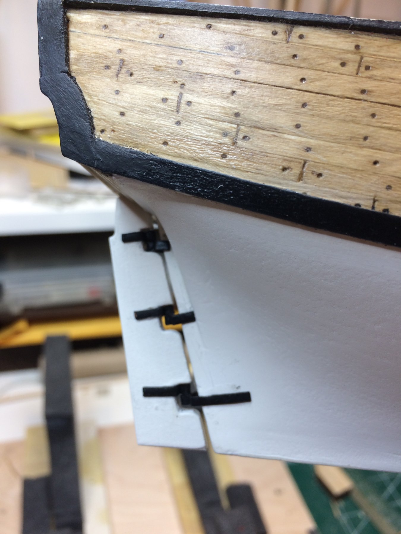
Work on waterways was completed yesterday. The only building step left is to give a concave shape to installed waterways. Today.
After shaping i give waterways quick dip into stain, leave stain to penetrate about 10sec and wipe it off with paper towel. The waterway at the bow was dipped into water for about 5 min and the curve was achieved by twisting it on the plastic cover. It was there until all other waterways were installed. The gained curvature was giving to waterway perfect fit at the bow.
Other waterways installed..


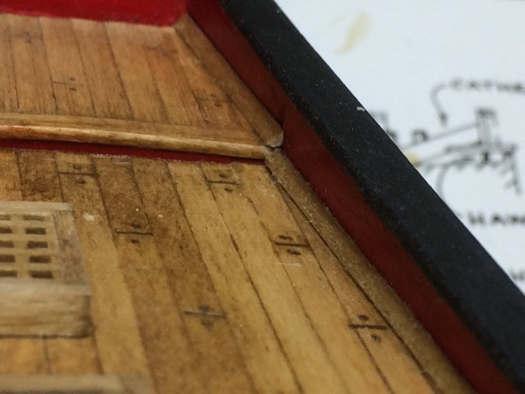
Then i marked places for drilling the scuppers. Used one unsuccessfully shaped waterway and marked 5 dotes. Transfered it to both main deck waterways and drilled the holes. The holes were not drilled all the way thru, the drilling bit was 0.8mm.

In the hull, scuppers were drilled under the angle, again not all the way thru. Holes were then shaped with a small file.
The bow waterway was installed the last.
And the whole assembly..

Happy modeling.
- lmagna and Overworked724
-
2
-
16 hours ago, lmagna said:
Impressive work for a small item. But it seems like you are doing a lot of that lately. Large effort into small details making for an increasingly nice build. Your extra effort is making this kit stand out.
Yes, it appears to be just like that, smaller scale model and lots of small items. Only challenge i see is no adequate tools to do the job.. Thanks for encouragement..
-
Today is all about waterways... The waterways are very tiny on this model, 1.2mm (or close to) by 1.2m... Had some challenges how to shape them into correct form to make them ready for final, concave shape. Tried with sanding block, tried with a diamond file, carving knife, nothing was coming out as acceptable result.
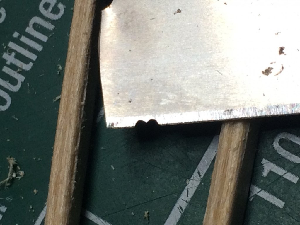
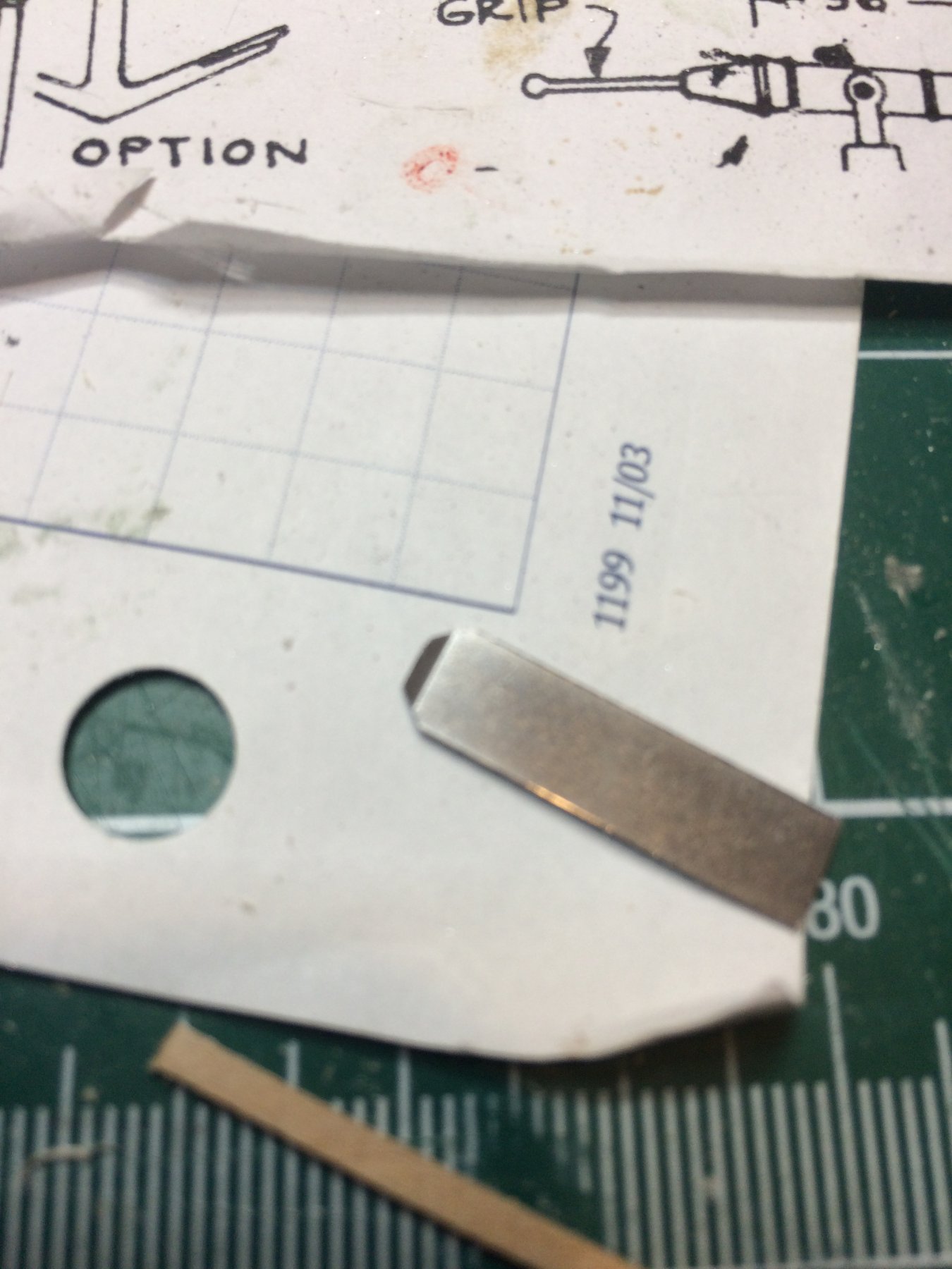
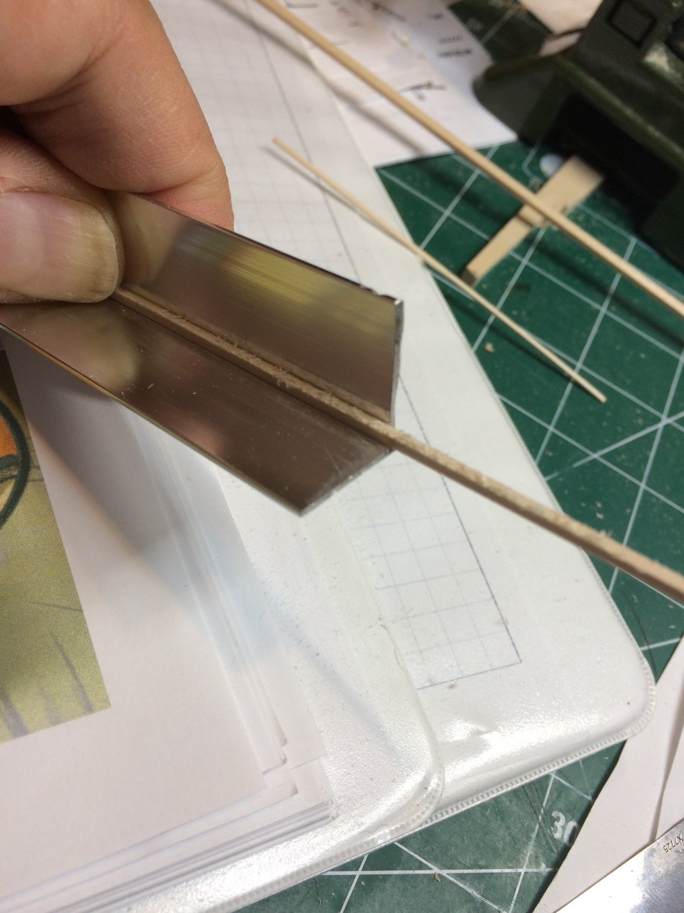
Then i decided to make my own tool. Going back to elementary school the 90 degrees angle with 1.2mm base and altitude lengths ends up with appr 2.8mm (or close) of hypotenuse...
One old chisels was used to make a scraping tool...

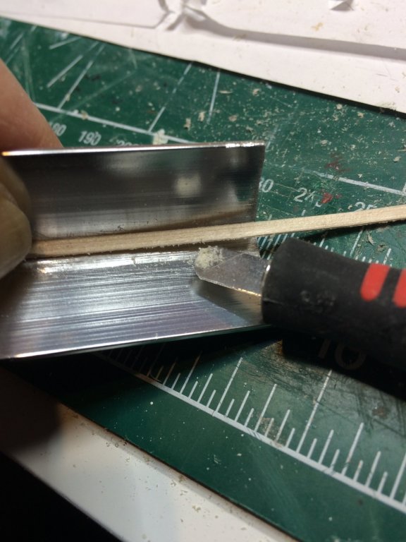
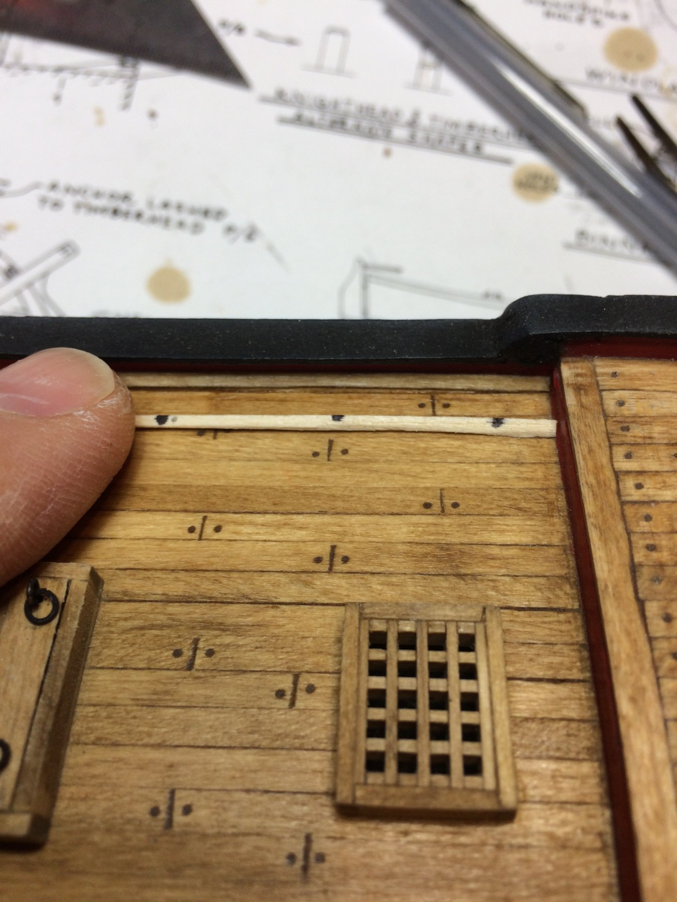
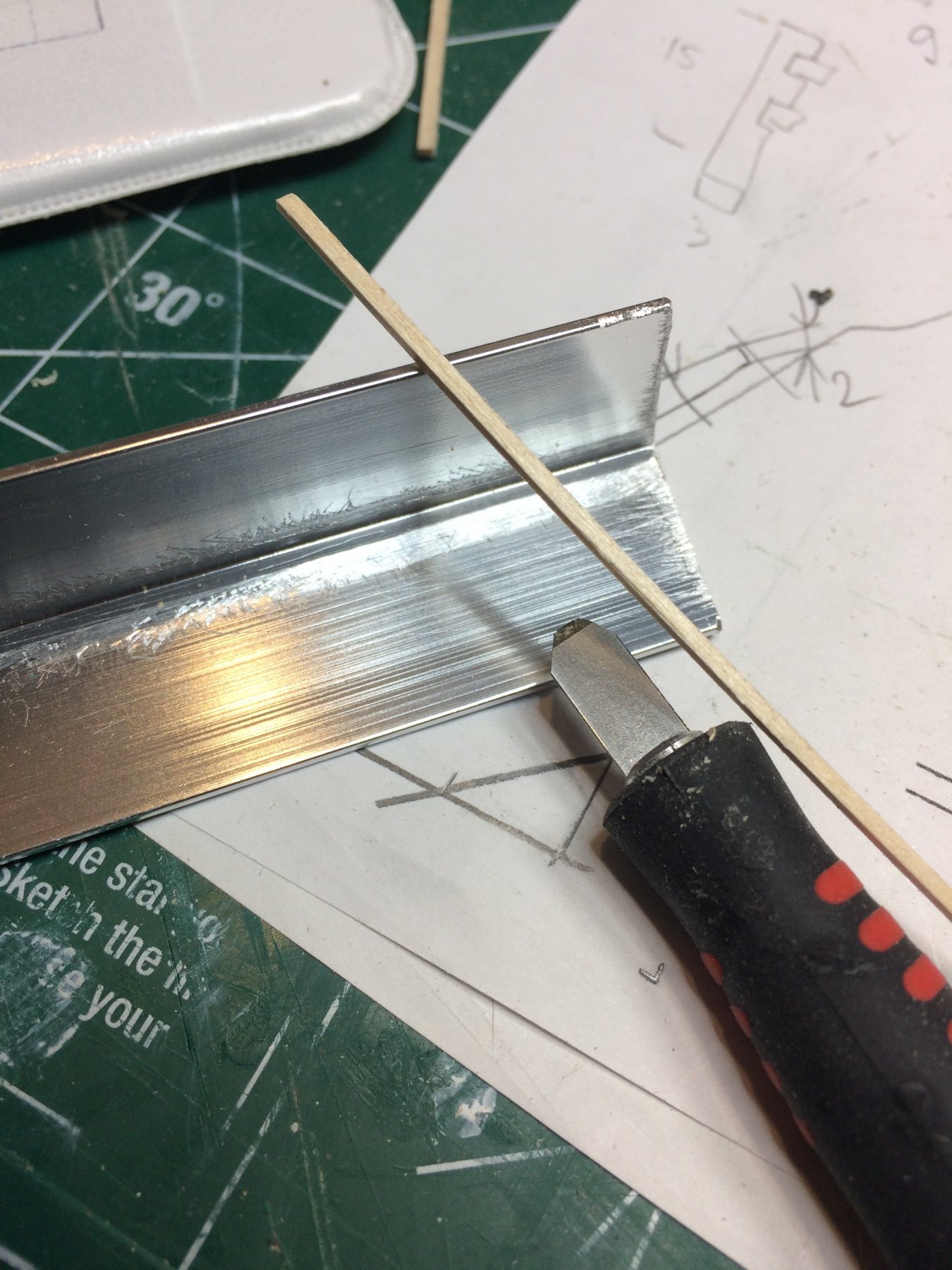
Then as a "molding" holder, i used small piece of L shaped aluminum profile. The waterways are made out of basswood, cut in 1.2x1.2 mm size. I cut several small pieces in the length that corresponds to the place on the ship where it will be installed.
Scraping was done in small increments; 2cm scraping then move forward, 2cm scraping then move forward...
Setup...

Molding in place, ready for scarping..
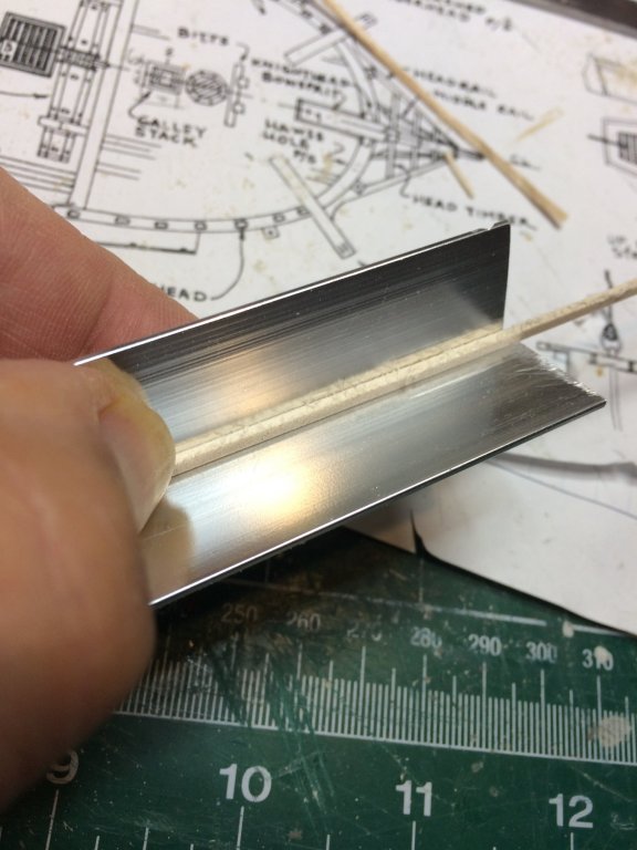
Worth to mention that growing a bit longer thumbnail will help holding this tiny piece in place while scrapping... :-)

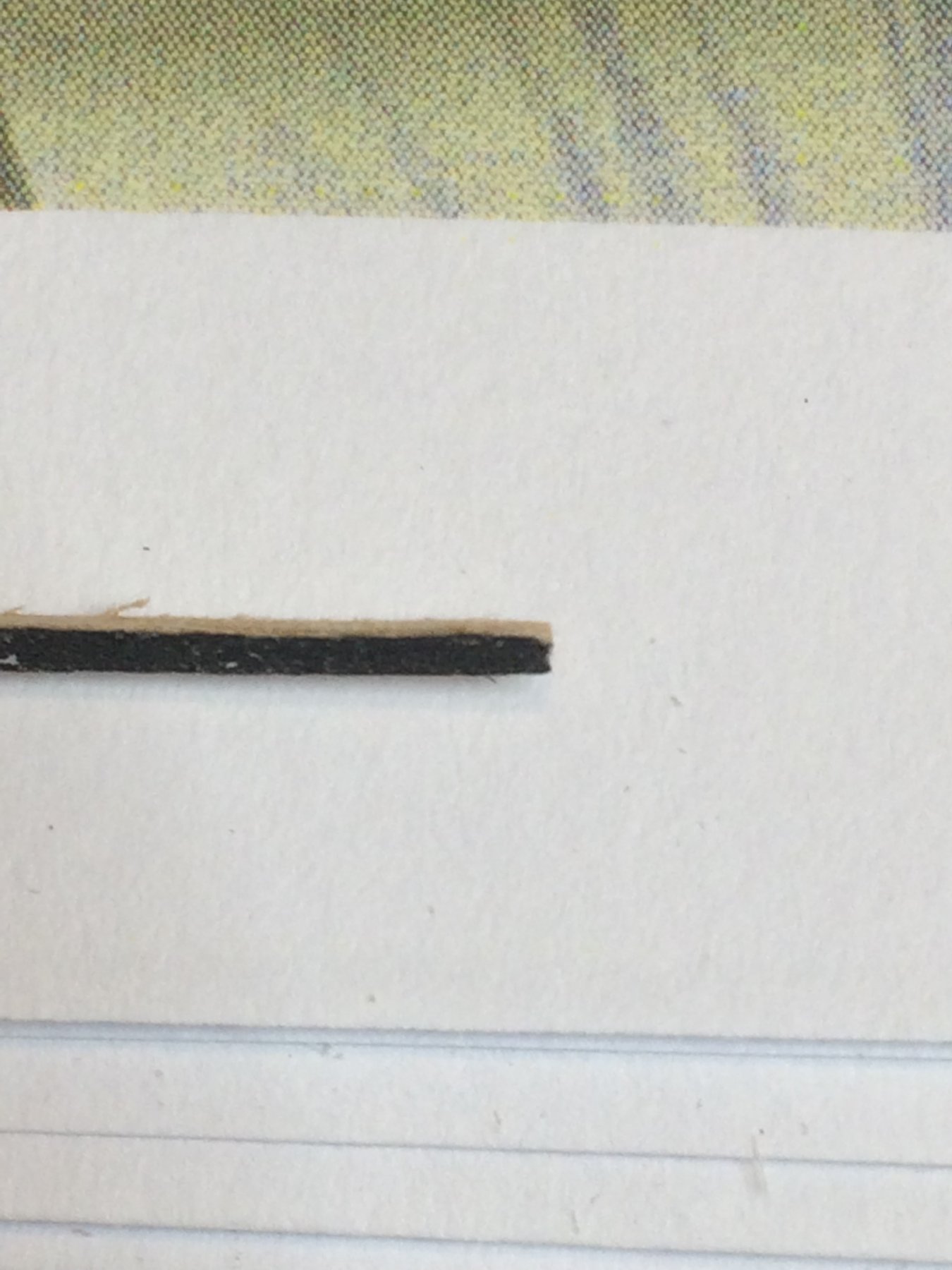
In the middle of the work....
End result...

It is a bit hard to focus my phone's camera...

And all waterways done and ready for assembly.
Next step will be to mount them all and shape them to final, concave form...
Happy modeling..
-
-
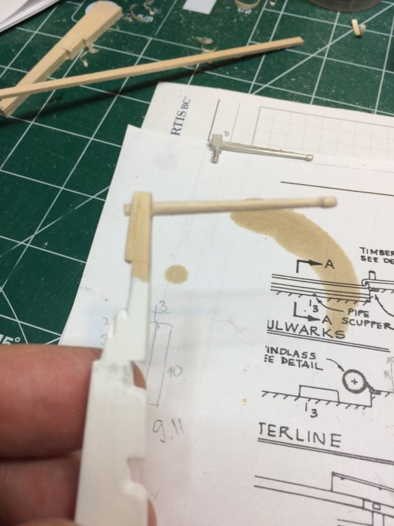
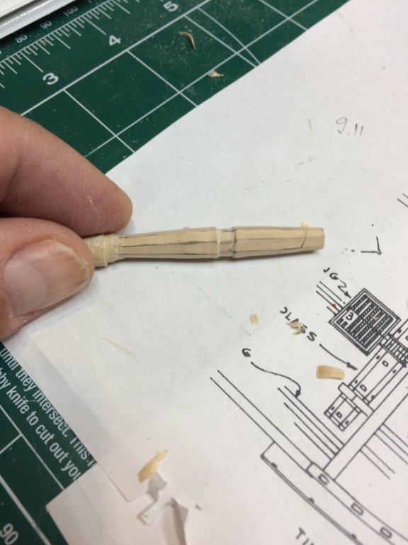
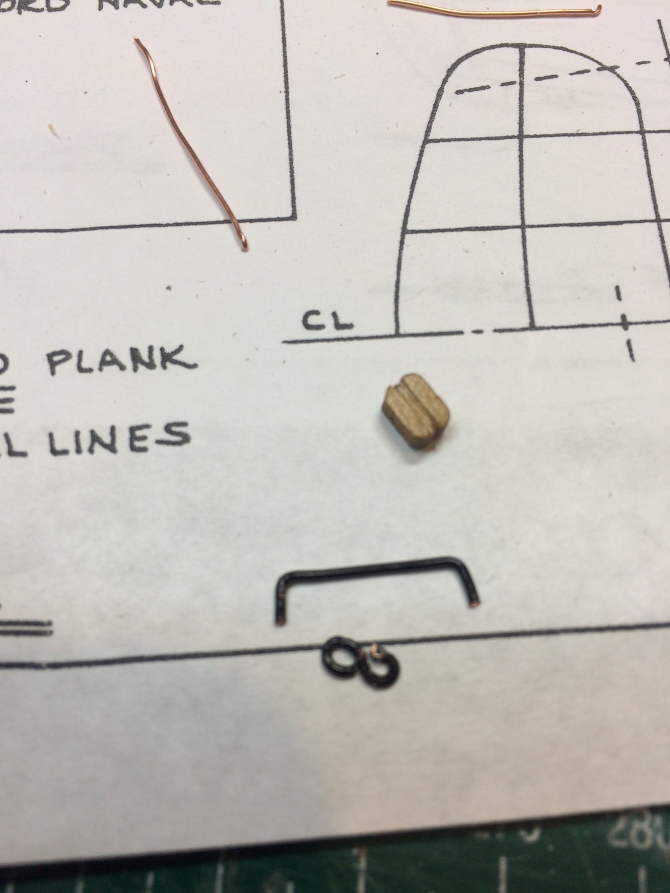
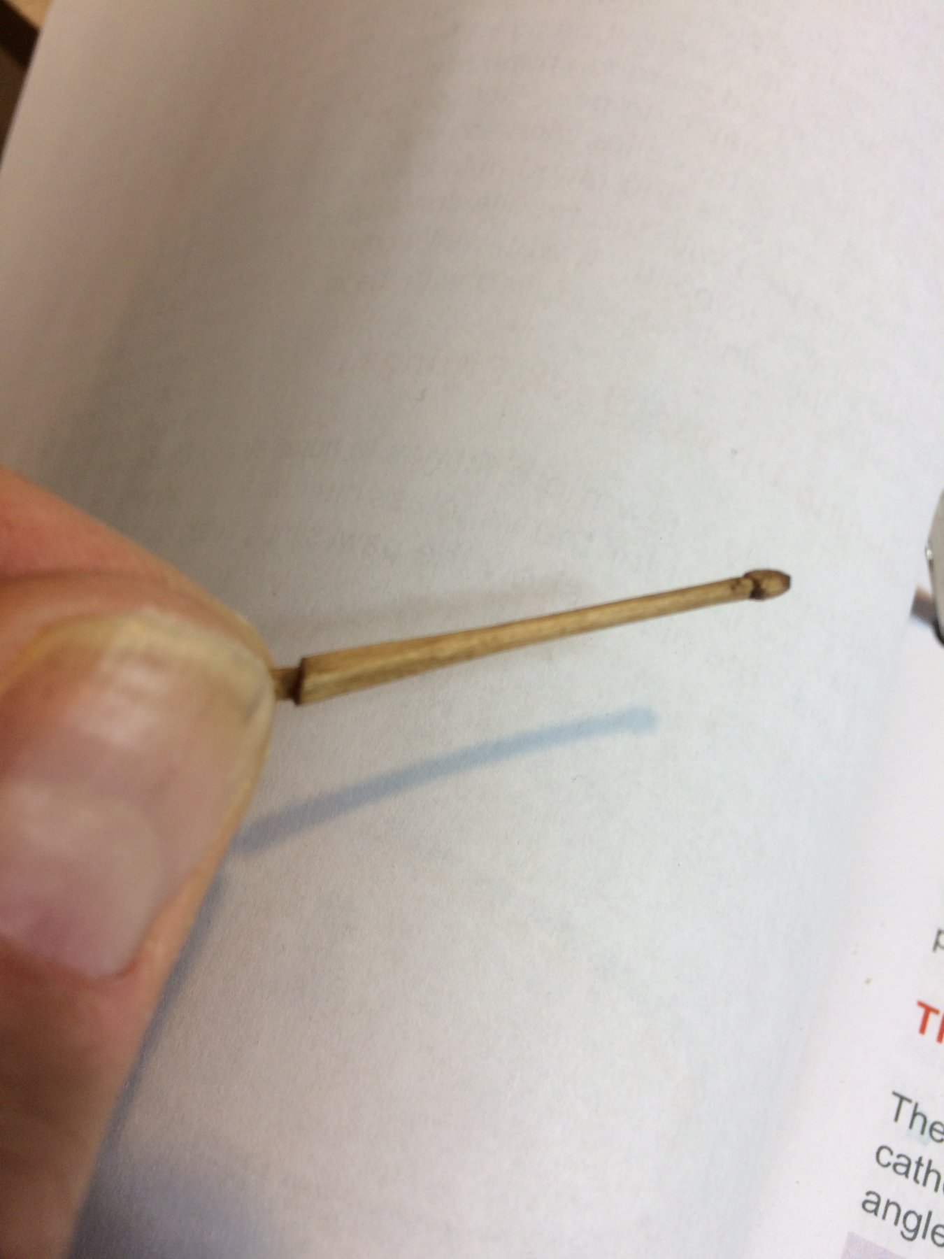
Today i completed a tiller and got it ready for mounting on the rudder.
Piece of basswood, 3mmx3mm, sanded to match kit supplied one and tested to fit on the rudder.
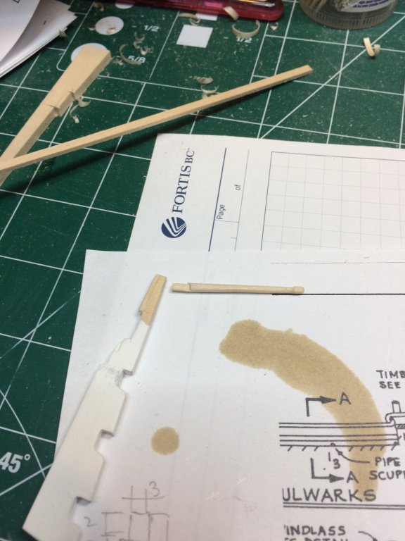
Compared to kit supplied...
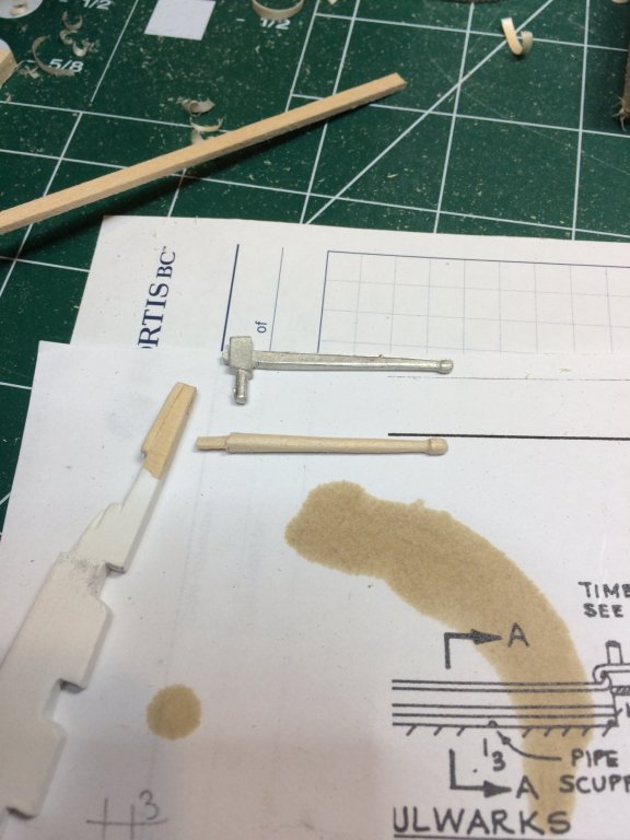
I might need to shape it a bit to retain square shape towards the rudder. It is hard to see on pictures at this moment..

Before the final assembly, need to square the end and stain it.
Happy modeling.
-
12 hours ago, lmagna said:
Nicely done. One more item that you can point at and say that you personally made it.
Thanks Lou. There will be few of those custom-made items but must say lots of fun and calming minutes. Instead of listening relaxation music i rather build ships and parts from scratch. :-)
-
-
-
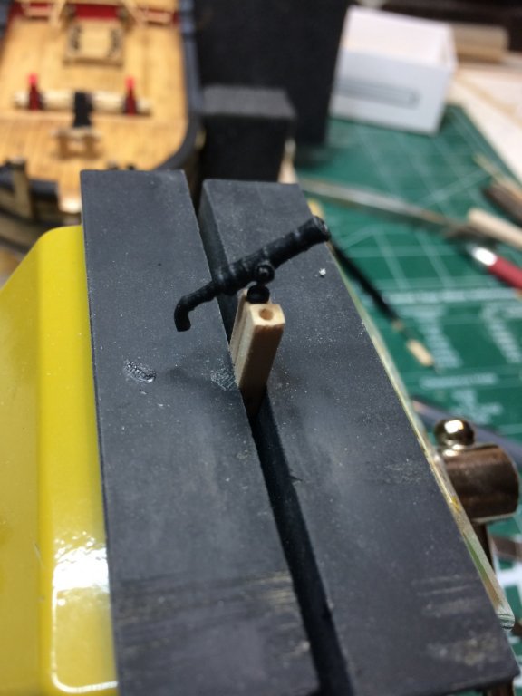
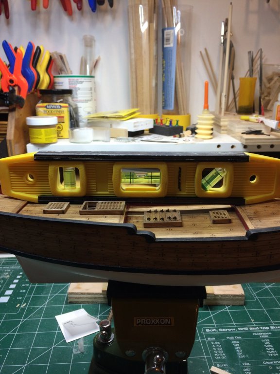
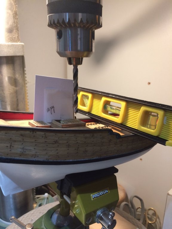
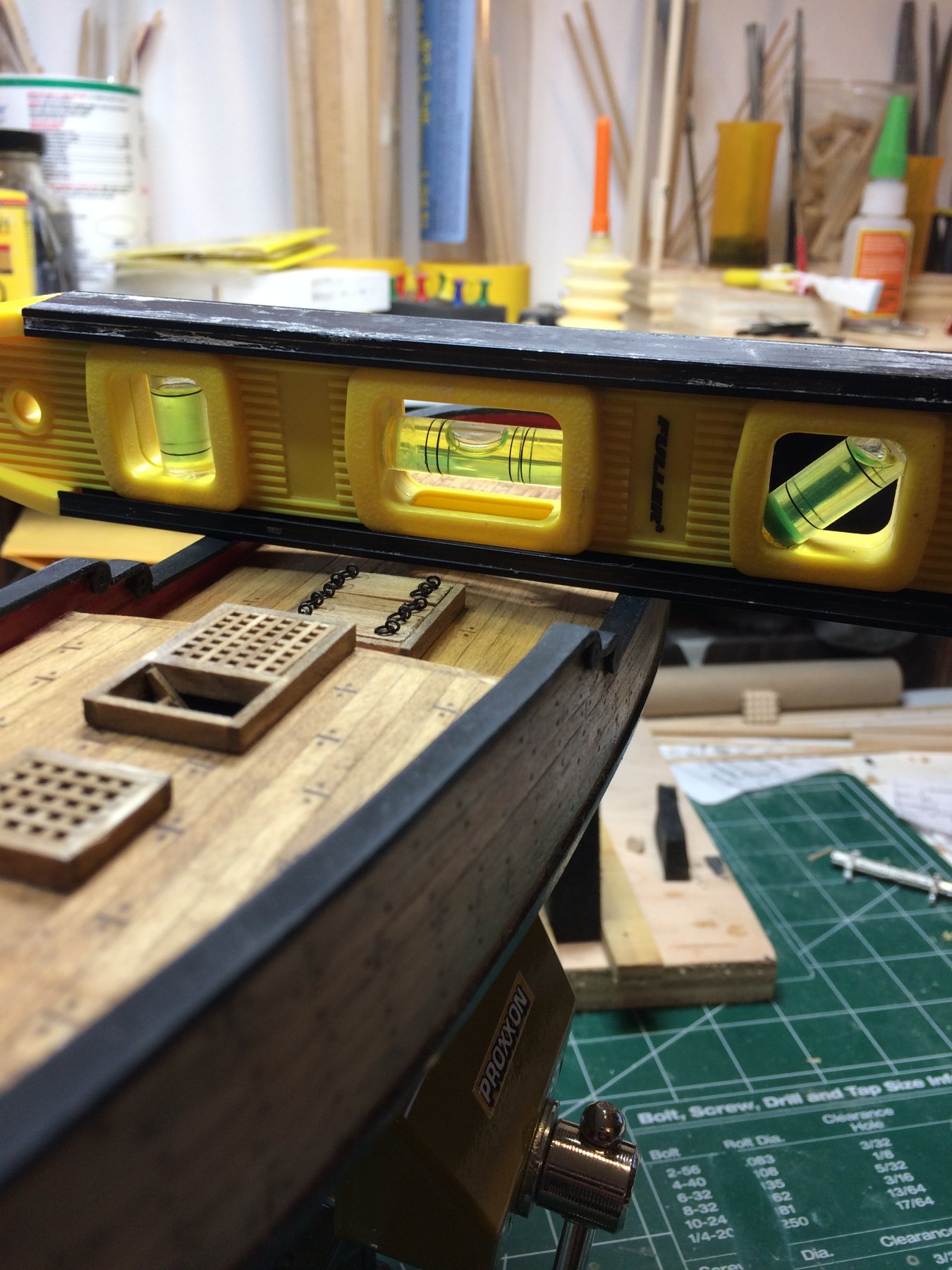
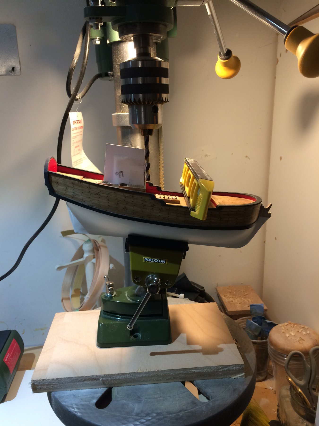
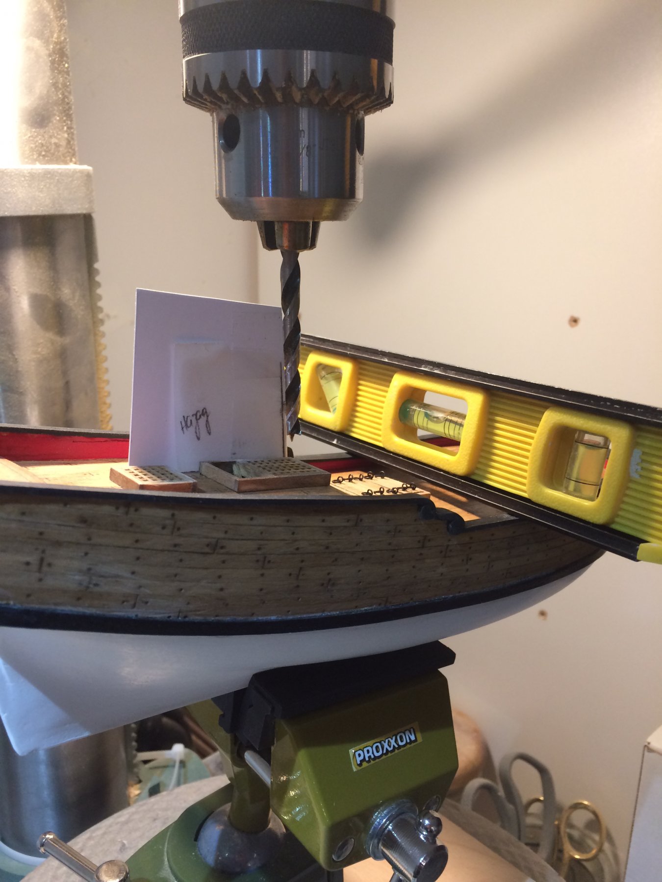
No much to report today. Just drilling two holes in the deck for masts...
Had to make a template to match the angle of the masts. Traced the angle from the plan on transparent paper, glue it on cardboard and cut the cardboard.
Then i put a ship on the vise, making sure it sits on it with right angle. The ship was put on bench press with 6mm bore, the vise was moved to match correct angle and hole were drilled. The hole was appr 3cm deep.


Happy modeling..
-
-
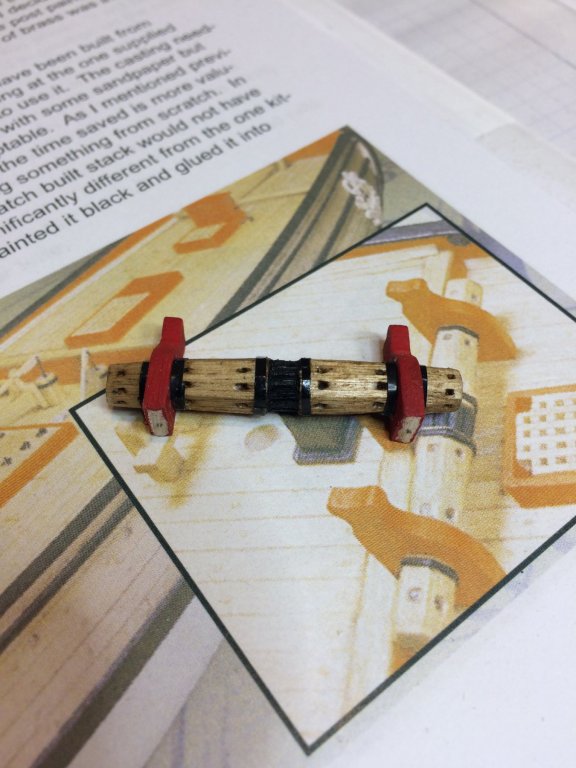
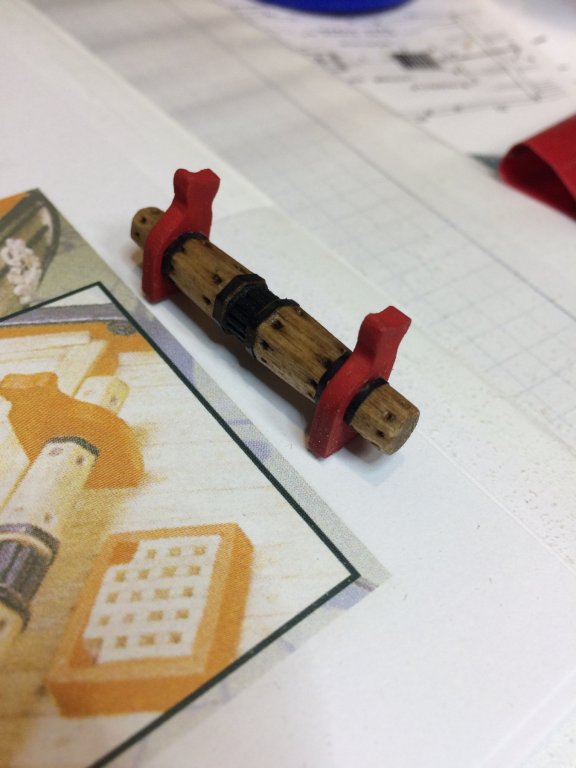
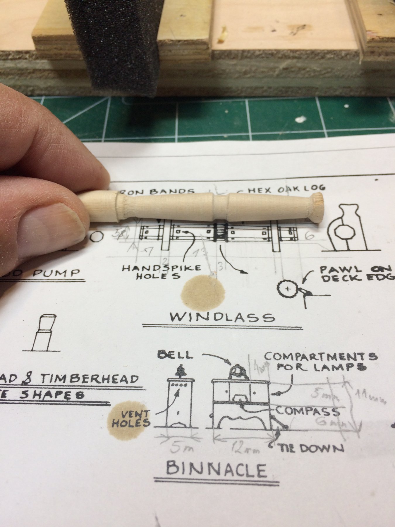
Windlass, part three or how i would call it a final build. Unless i spot some badly build part or completely missed dimension or fall of assembly this will be the final attempt..
So, here it is, final product, attempt #3...
So, how did i get here?
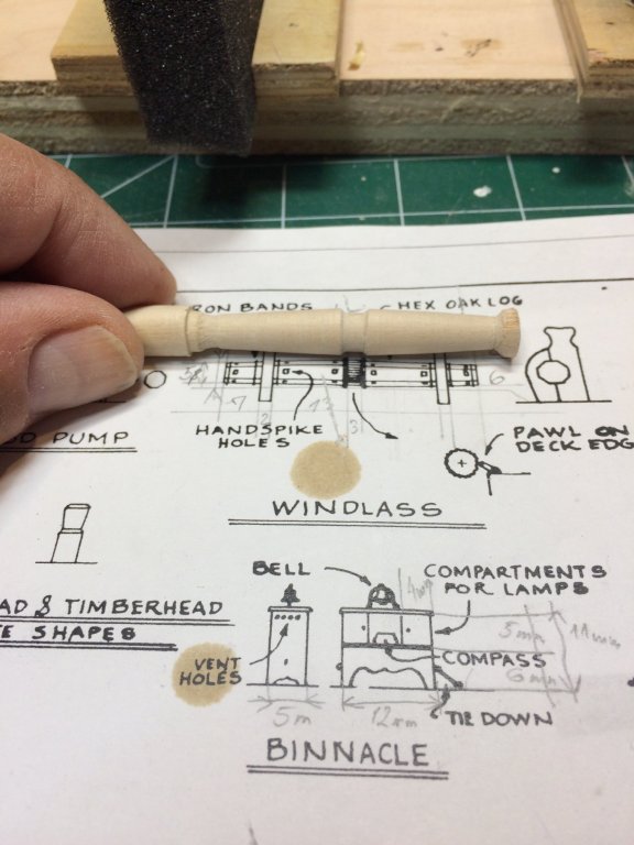
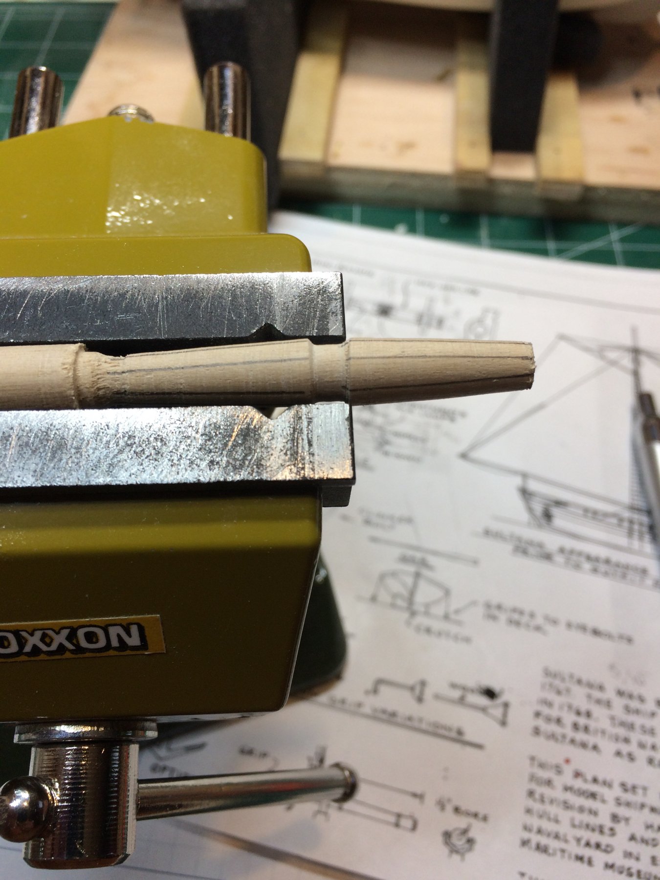
First get a wood dowel appropriate size, 1 mm wider that needed, cut it in 12cm length piece and with small lathe, shape it to approximate dimensions: middle part was 8mm wide which left me 1mm room while cutting the octagonal lines. The end parts were at 6mm leaving me 1mm for octagonal...
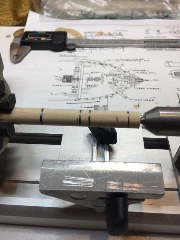
Then i marked 8 lines for octagonal shape..

With a small chisel i cut 8 lines to make octagonal shape.
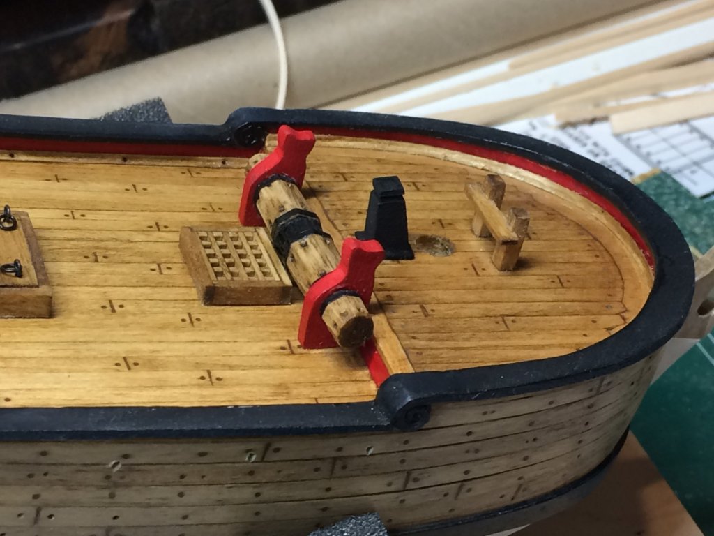
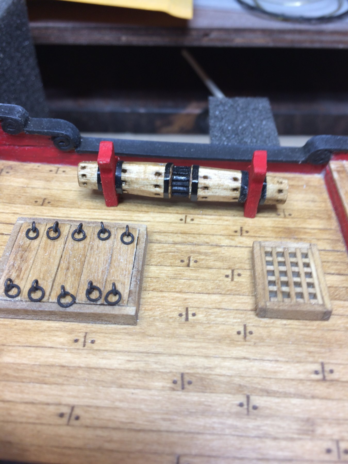
Lots of shaping, scratching, sanding... Carved the center sprocket, then paint it in black, electric tape was used to simulate iron bands, small nail was used to shape the wholes on windlass, the whole windlass was dipped into stain and after 30 second extra stain was removed with a bounty..
Two supports (red) were reused from previous attempt; all assembled and ready for a final coat of vanish to seal all together. This step will be done tomorrow when stain is completely dry..
That should be it..

Happy modeling..
- sawdust, GrandpaPhil, lmagna and 1 other
-
4


 another hurdle passed,


Sultana 1767 by moreplovac - FINISHED - Model Shipways - 1/64 - Colonial Schooner
in - Kit build logs for subjects built from 1751 - 1800
Posted
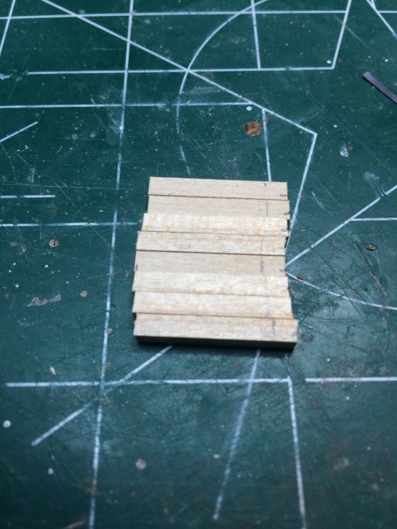
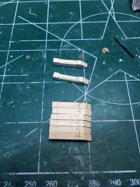
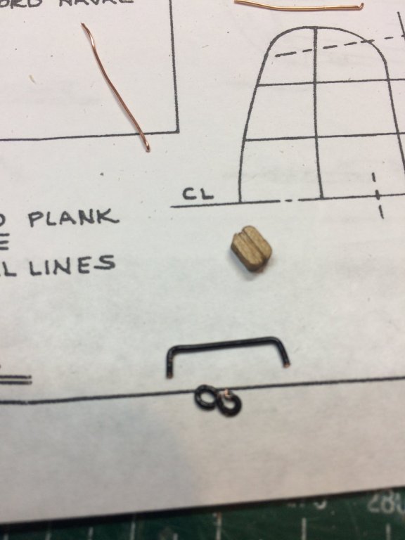
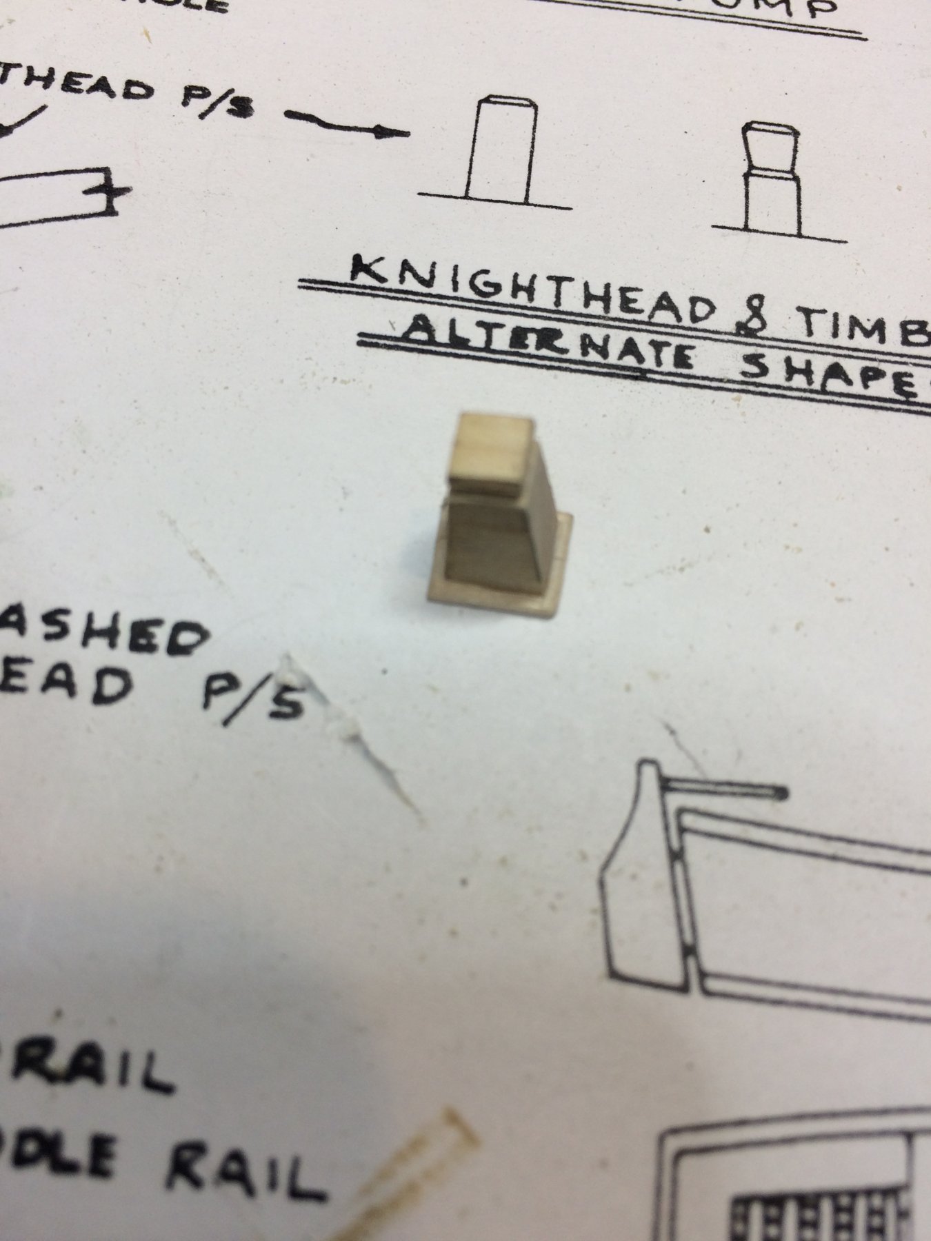
Timberheads are next. Those little things gave me some hard time, tiny, hard to keep between fingers but managed to get them all built. I built 30 of them, and picked 14 that happened to sticking out from crowd as best looking. I was thinking to organize a beauty pageant but was not quite sure if i would be able to come up with 14 different "i will fight for a world peace" sentences..
For building process i marked all 20 timberheads on one piece of plank, started from the top by sanding edges and with #10 knife, carved the shape and cut of the plank.
Building process..
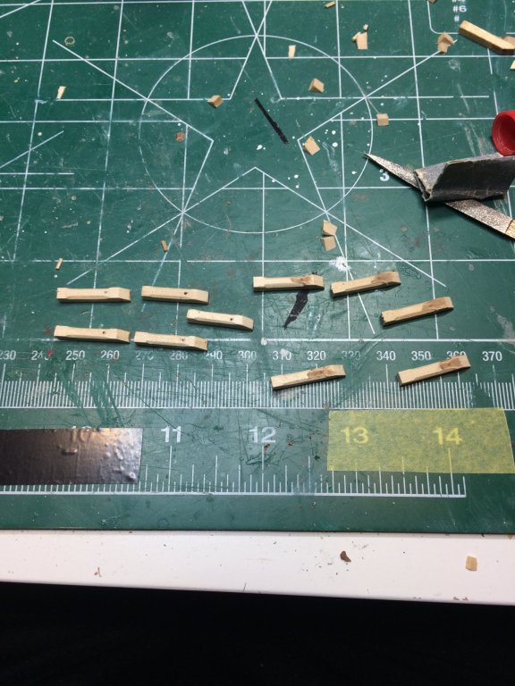
And the winners are ...
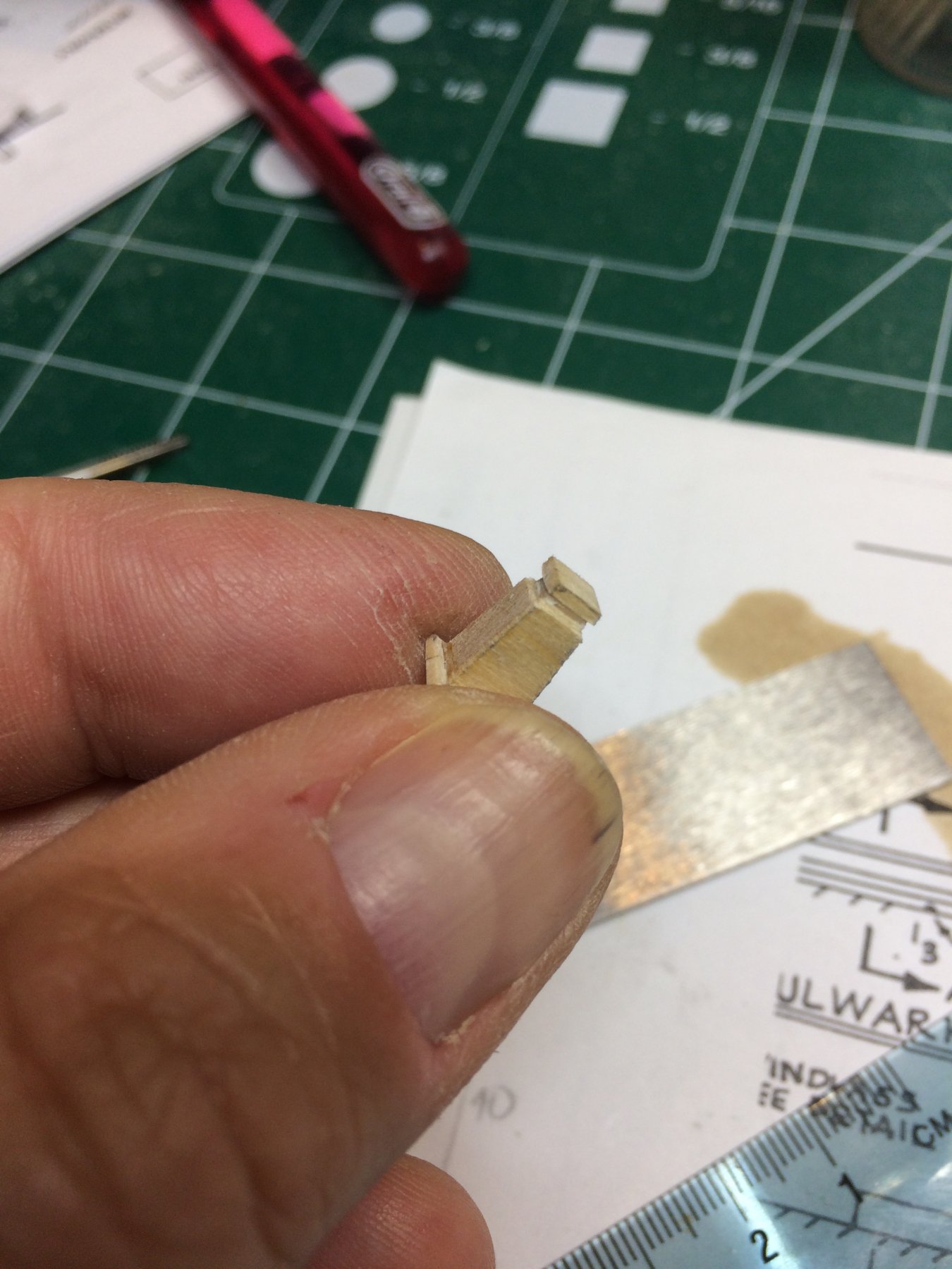
Then i added a small pin to each timberhead to make sure it will stay in the place, once mounted and glued.. A small pilot hole was drilled to the bottom of each one, proxxon with .44mm widened the holes and pin glued in the place.
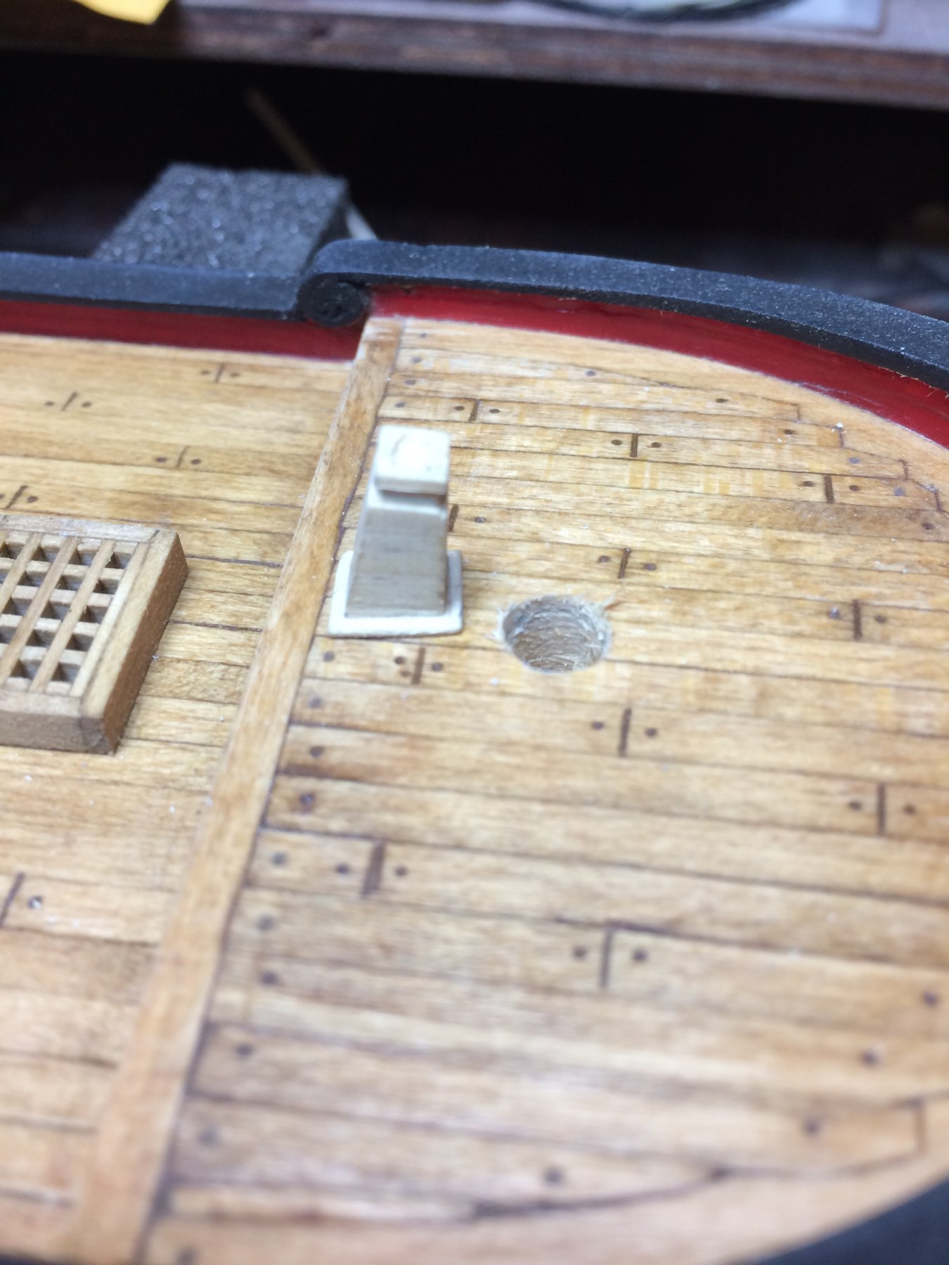
I marked the position on the cap rail for all timberheads, drilled a pilot holes and mounted them all, well not quite all. Still 9 to go. Tomorrow.
Once all are mounted a nice coat of flat black will be painted..
Happy modeling..