

moreplovac
-
Posts
709 -
Joined
-
Last visited
Content Type
Profiles
Forums
Gallery
Events
Posts posted by moreplovac
-
-
I started to work on deadeyes. The kit supplied one are 2.7mm in diameter. At first glance they shows a bit small and out of the scale for this model. In Chuck's practicum i did not find place where size of deadeyes is mentioned or i was tired and missed it completely.
The work on deadeyes was similar to what Chuck's was suggesting... with some additions. I measured the length of the whole deadeye assembly and mark it on the piece of wood (lets call it a board). Then two nails were pushed into board: one to hold a deadeye and another to hold the loop that will be nailed to the ship.. The 0.32mm wire was squeezed around the nail and around the deadeye forming the completed assembly.. Then i use a small amount of soldering paste and heat it to fill the gap between two wires...
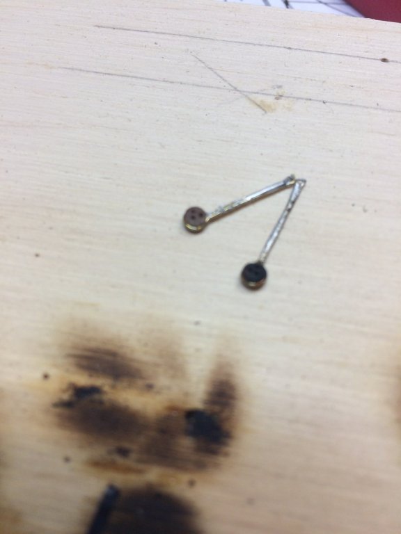
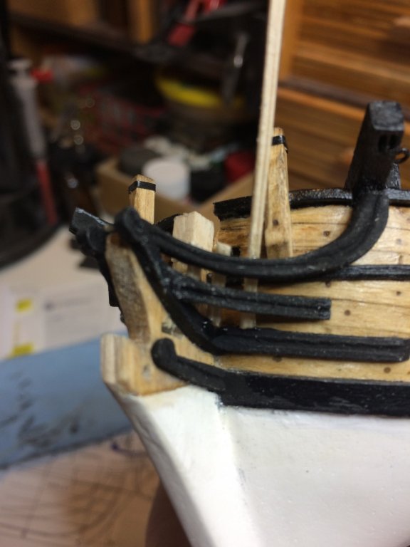
The intention is to paint the whole deadeye assembly in black. Then i decided to test it on the ship to see actually is it visually out of scale or just my eyes playing games with me...
Well for me, it does appear to be a bit out of scale... Then i made one home build deadeye just for testing in 3mm and 4mm size.. They looked a bit more appealing to the scale... My skills to build home-made deadeyes are not quite at acceptable level so i made purchase of few deadeyes from Chuck' web site... They are coming.... 3mm and 4mm. Will see which one fits better...
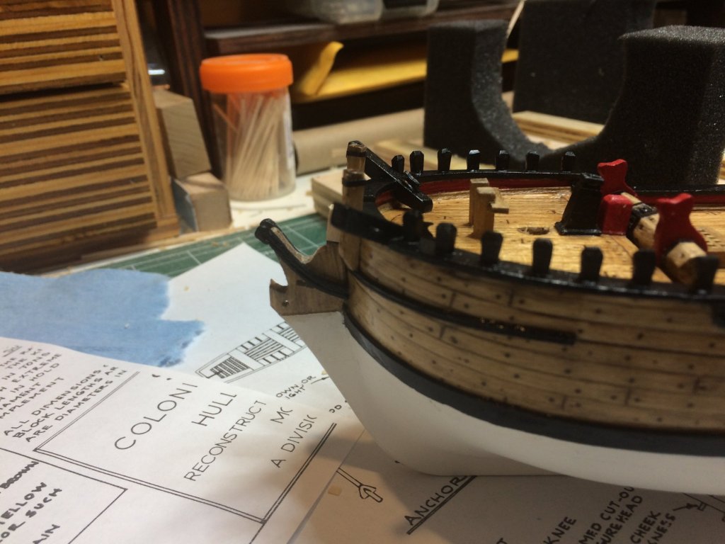
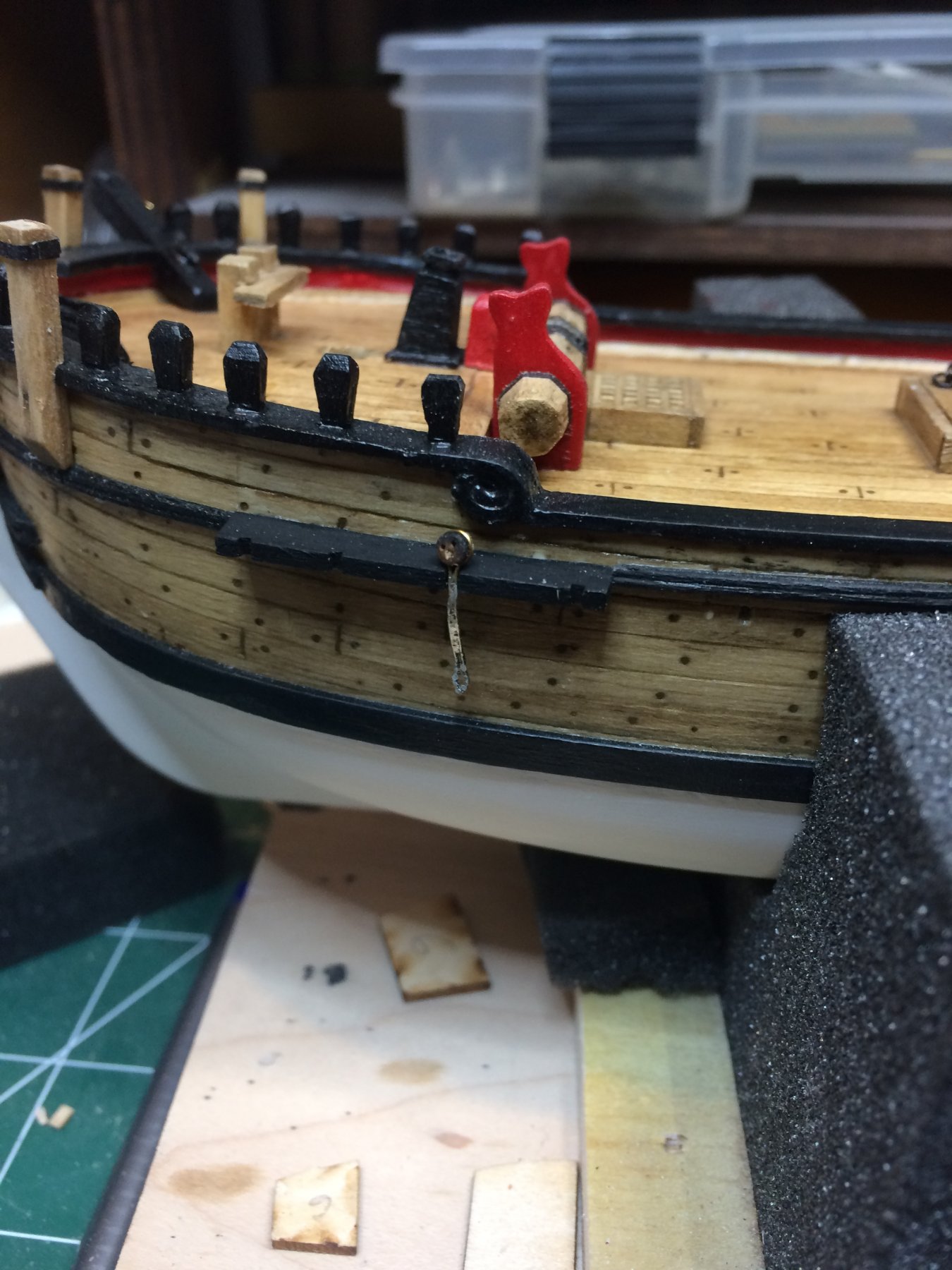
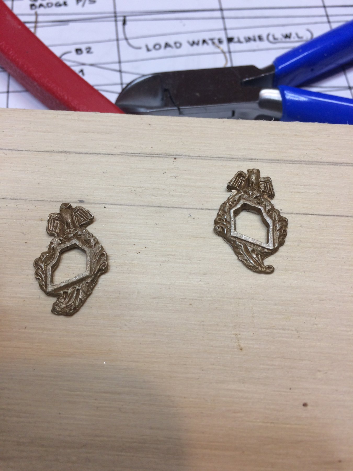
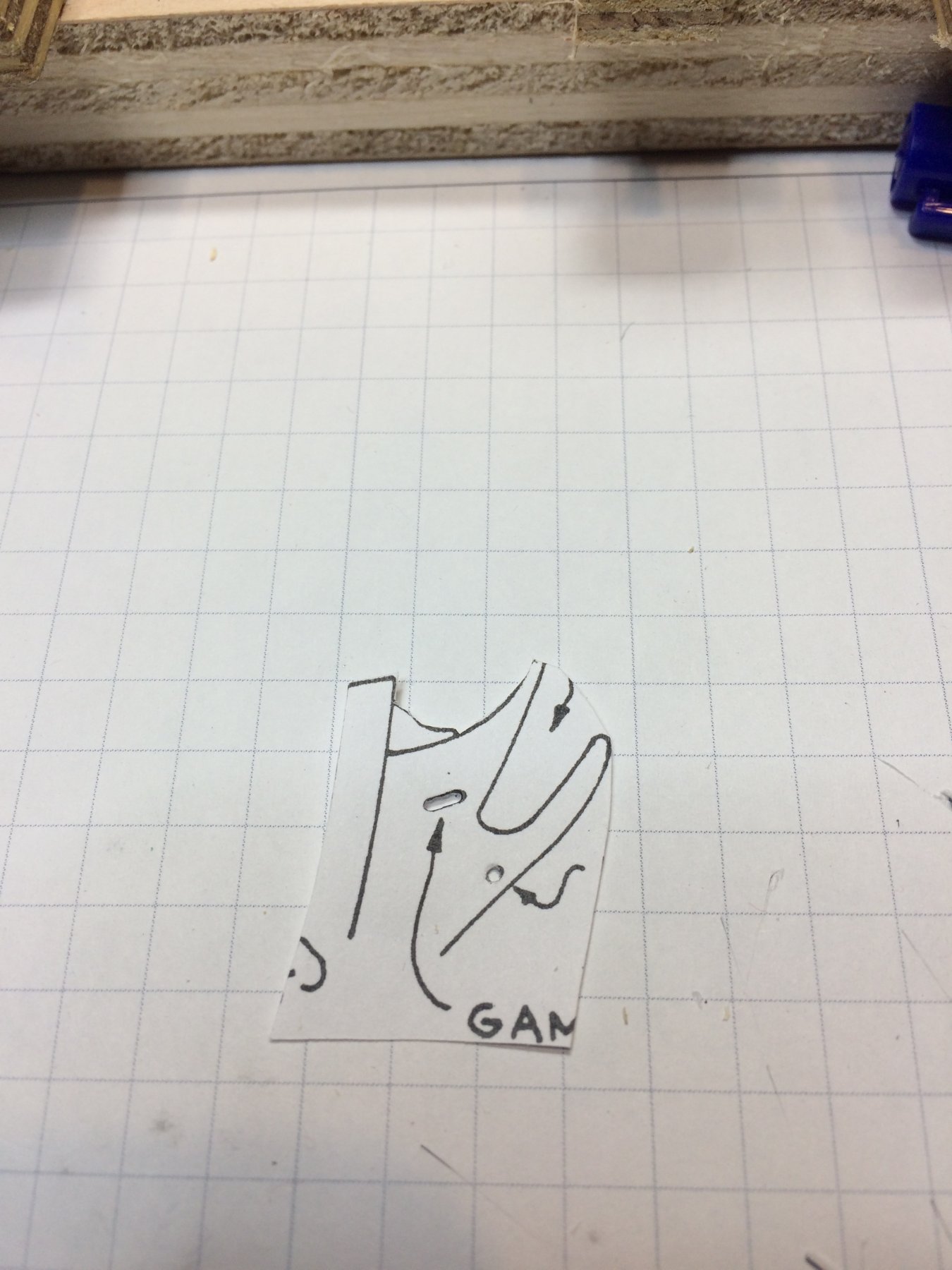
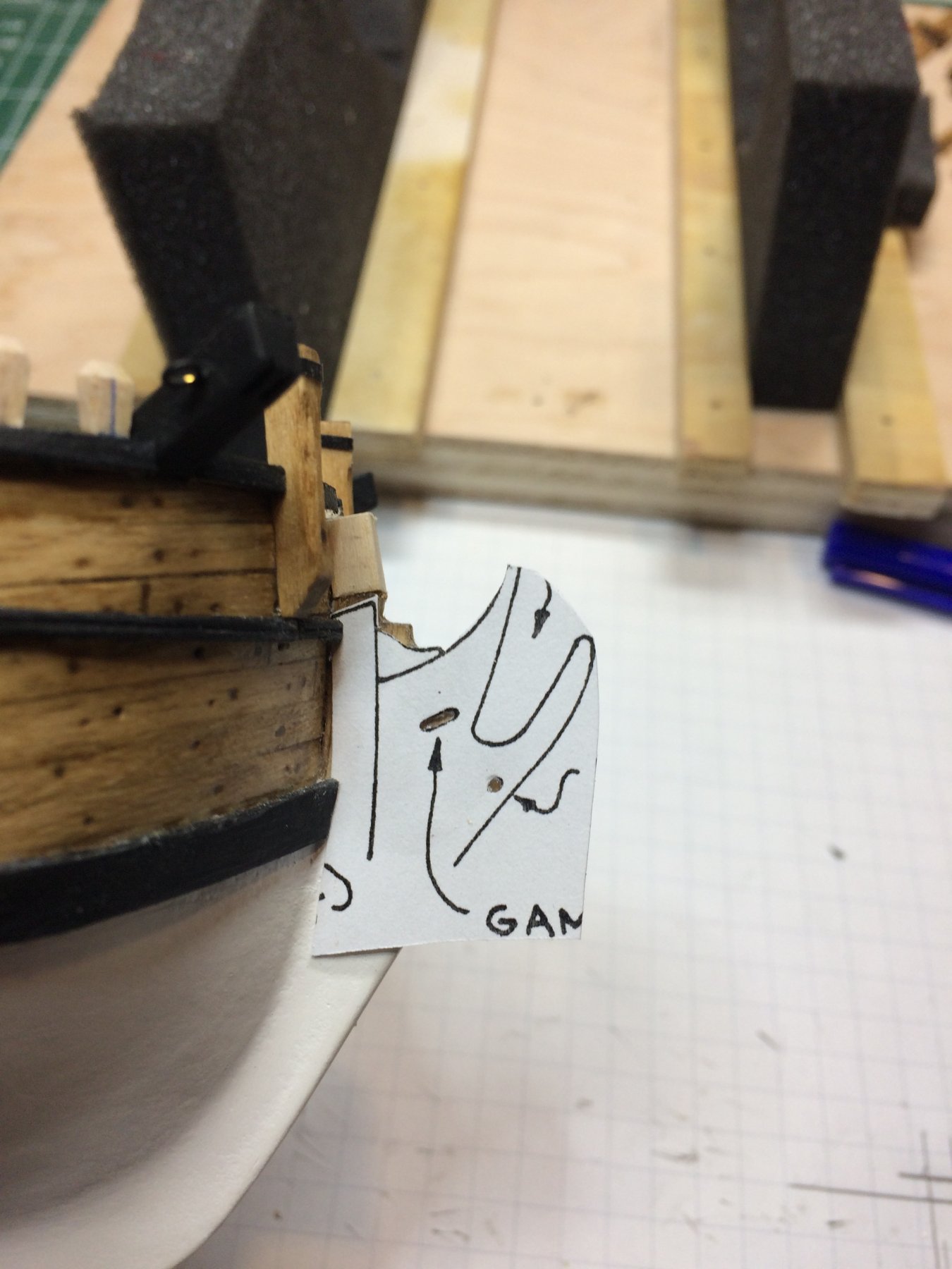
While waiting for deadeyes, i started to work on quarter badges. Following Chuck' practicum i tried to make one out of sculpey and must say was not quite successful. They were looking more like a squeezed piece of chew gum spit on the sidewalk then actual usable badges... They are tiny, very tiny... So, i decided to use the ones that arrived with kit.
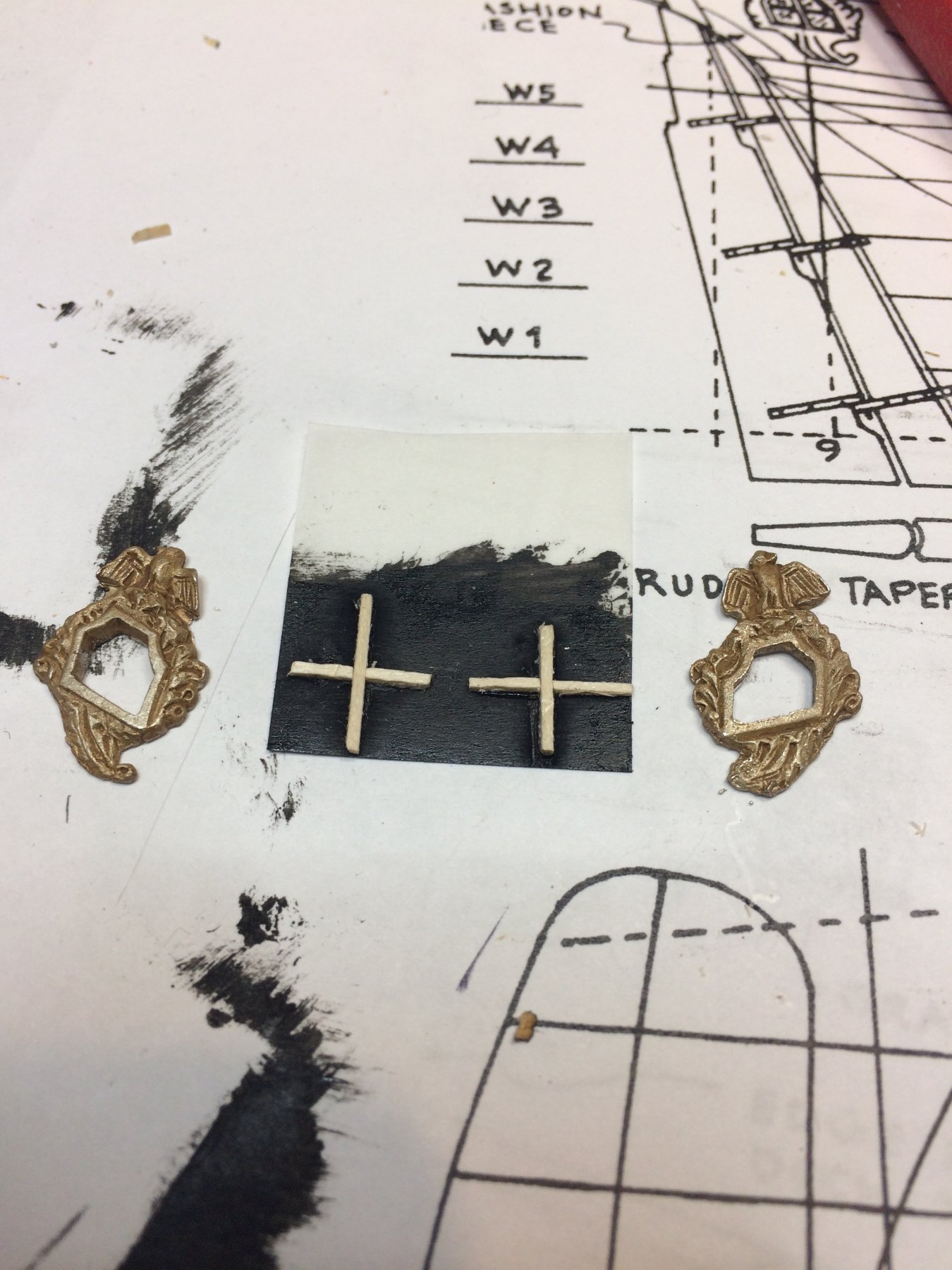
Clean them up a bit and cover with Tamiya earth color paint in attempt to simulate a wood.
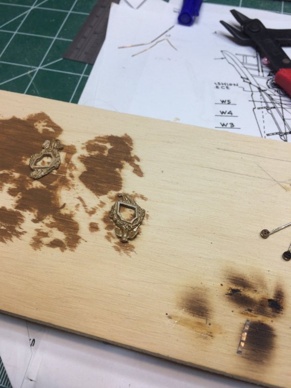
After drying, the excess paint was removed and they appeared to be ready for mounting..

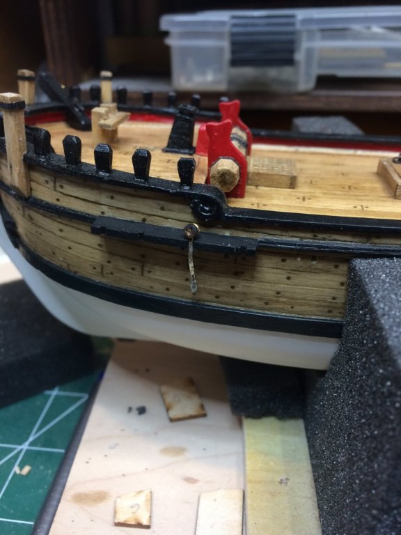
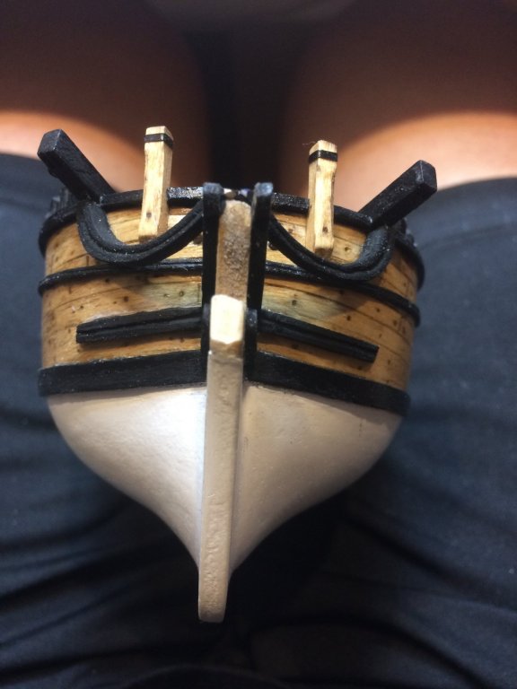
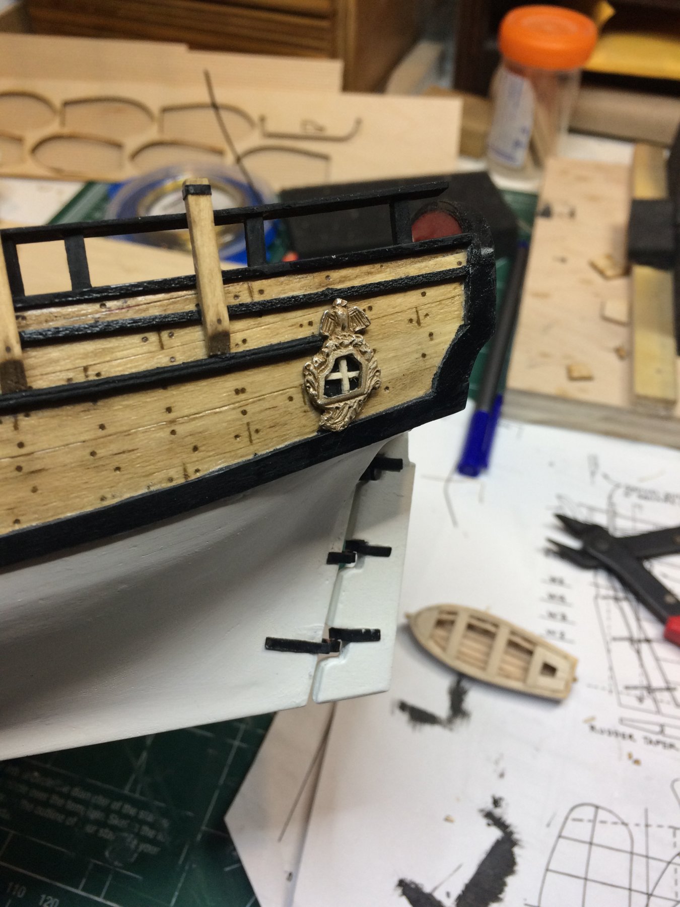
The windows were simulated with a tiny piece of wood and tracing paper colored in black..

Then badges were glued to the "window" and the whole assembly was glued to the ship..

Now when i looking this picture i need to fix that crooked window...
Happy modeling.
- jct, russ, Ryland Craze and 4 others
-
 7
7
-
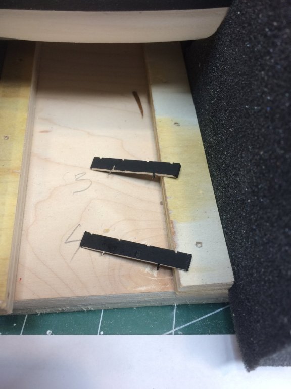
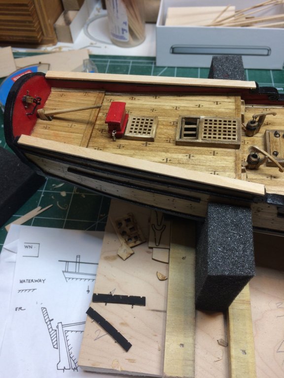
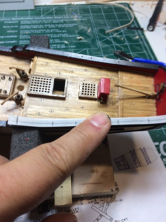
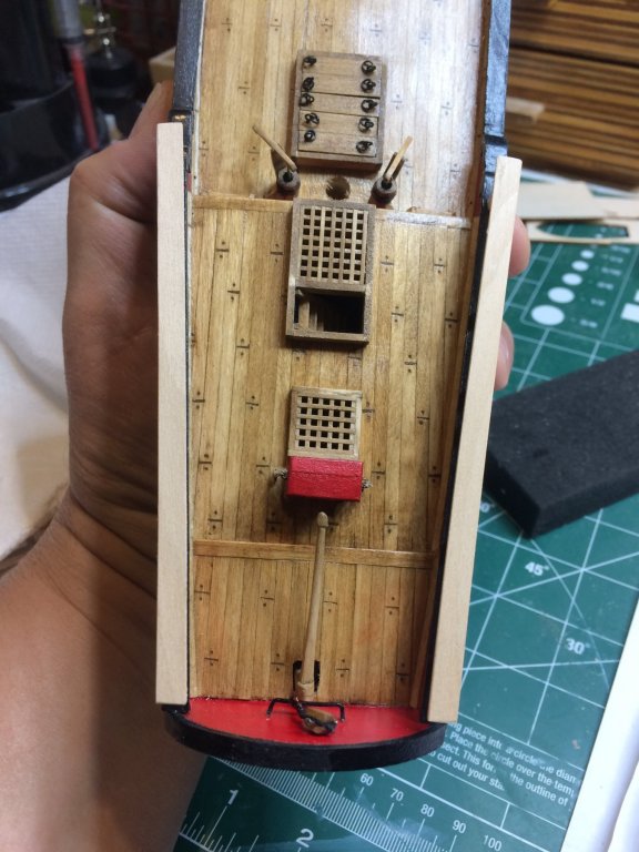
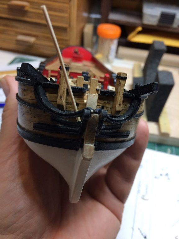
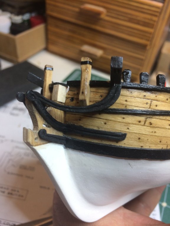
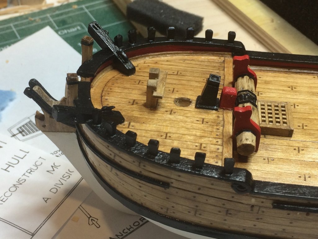
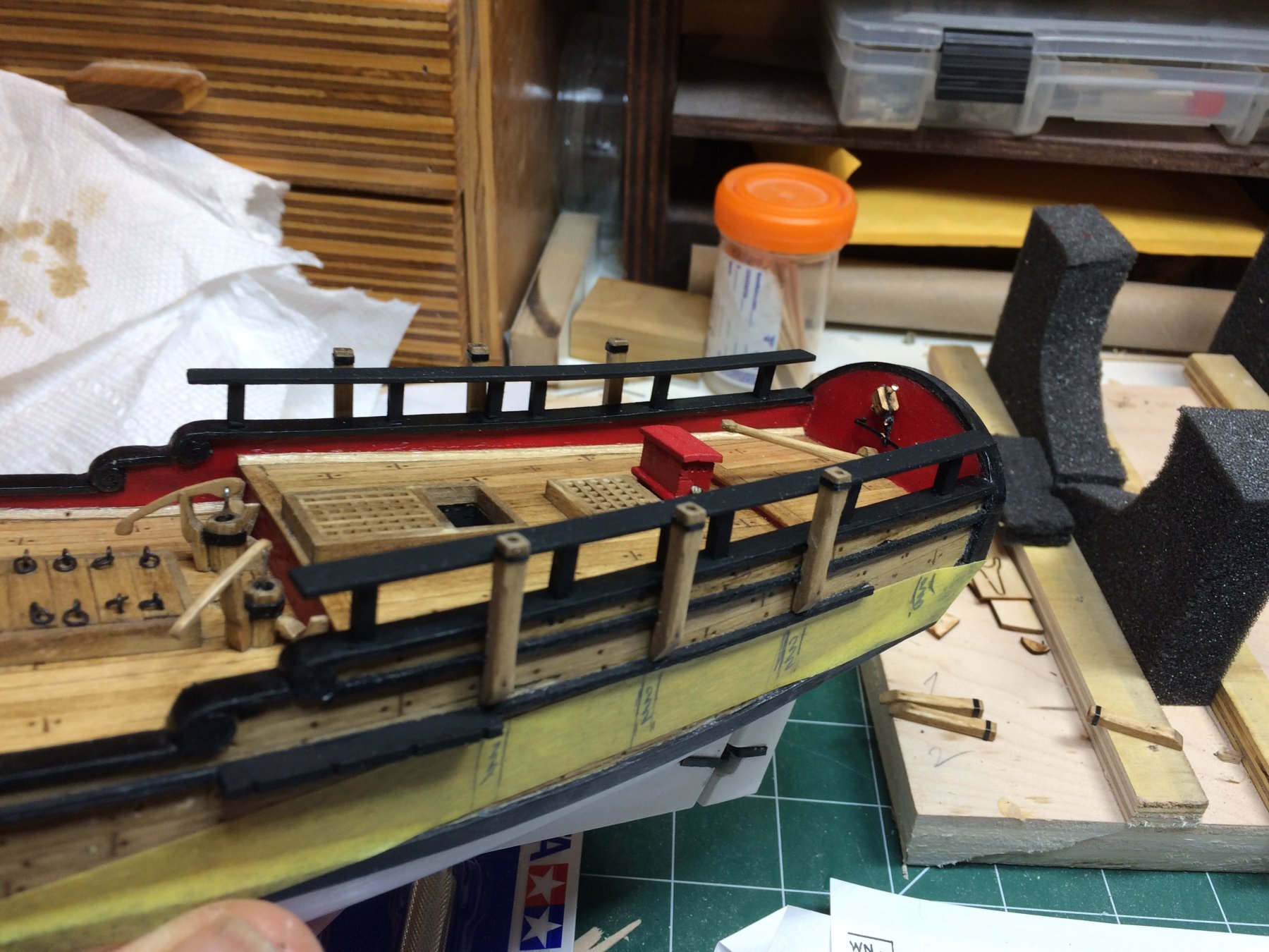
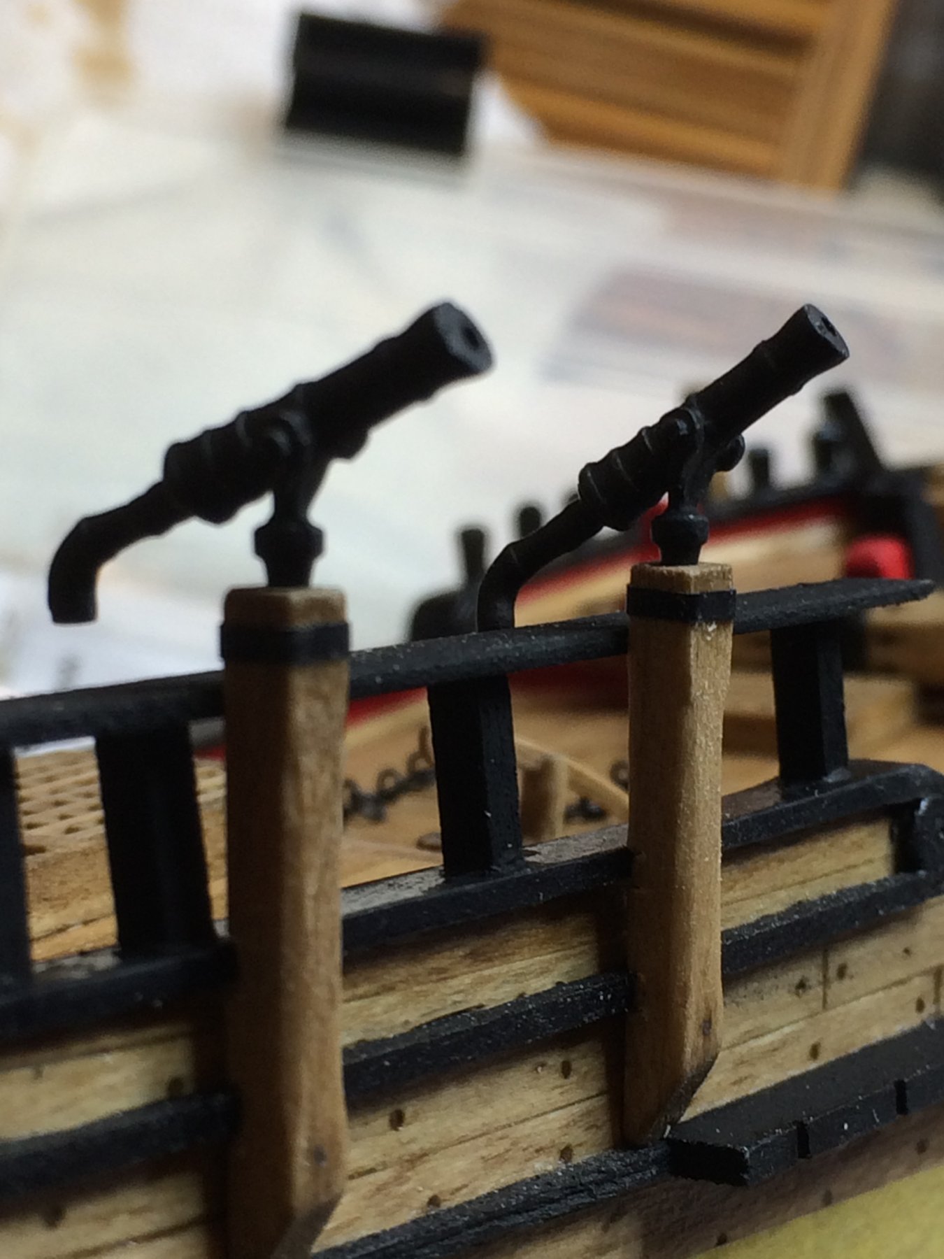
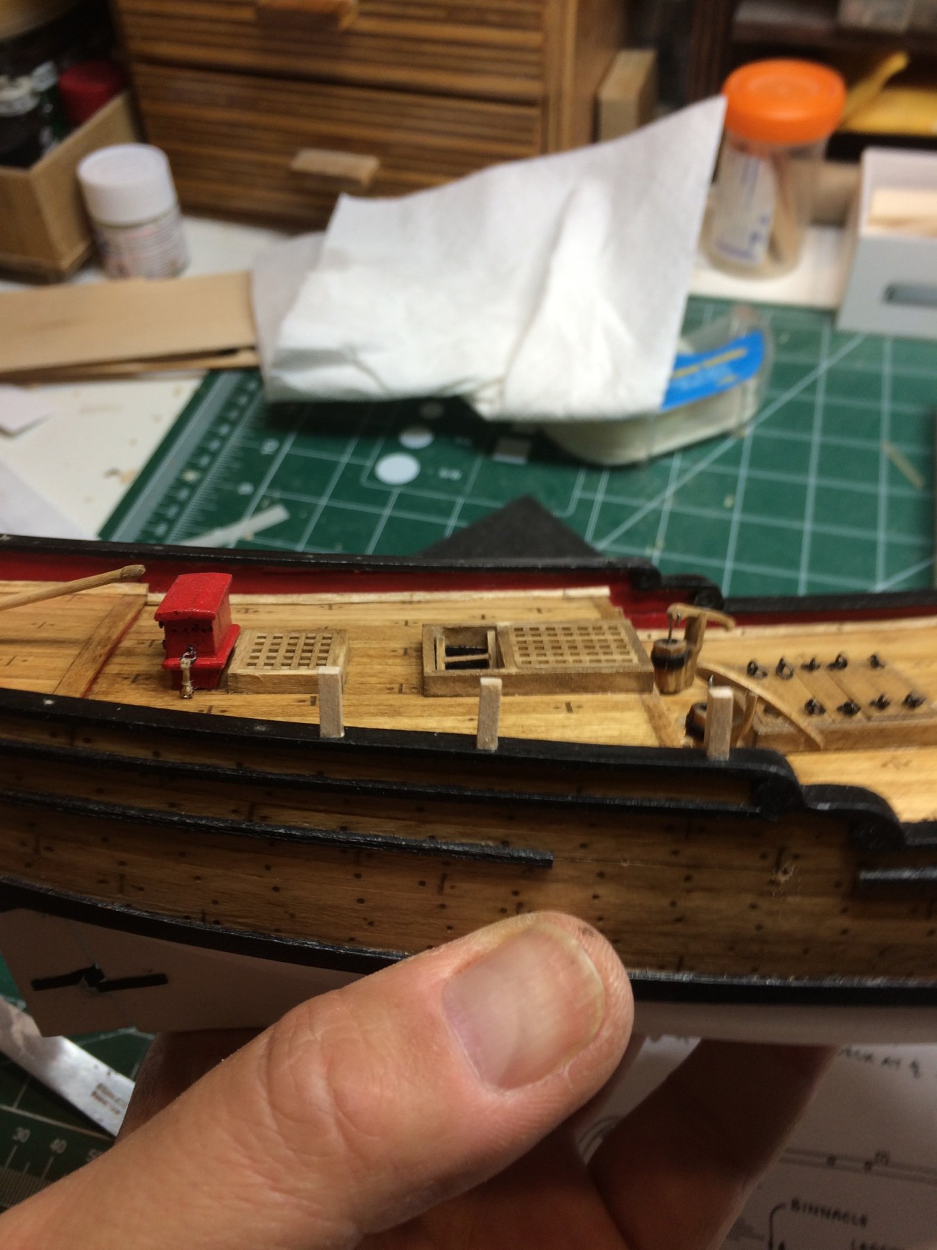
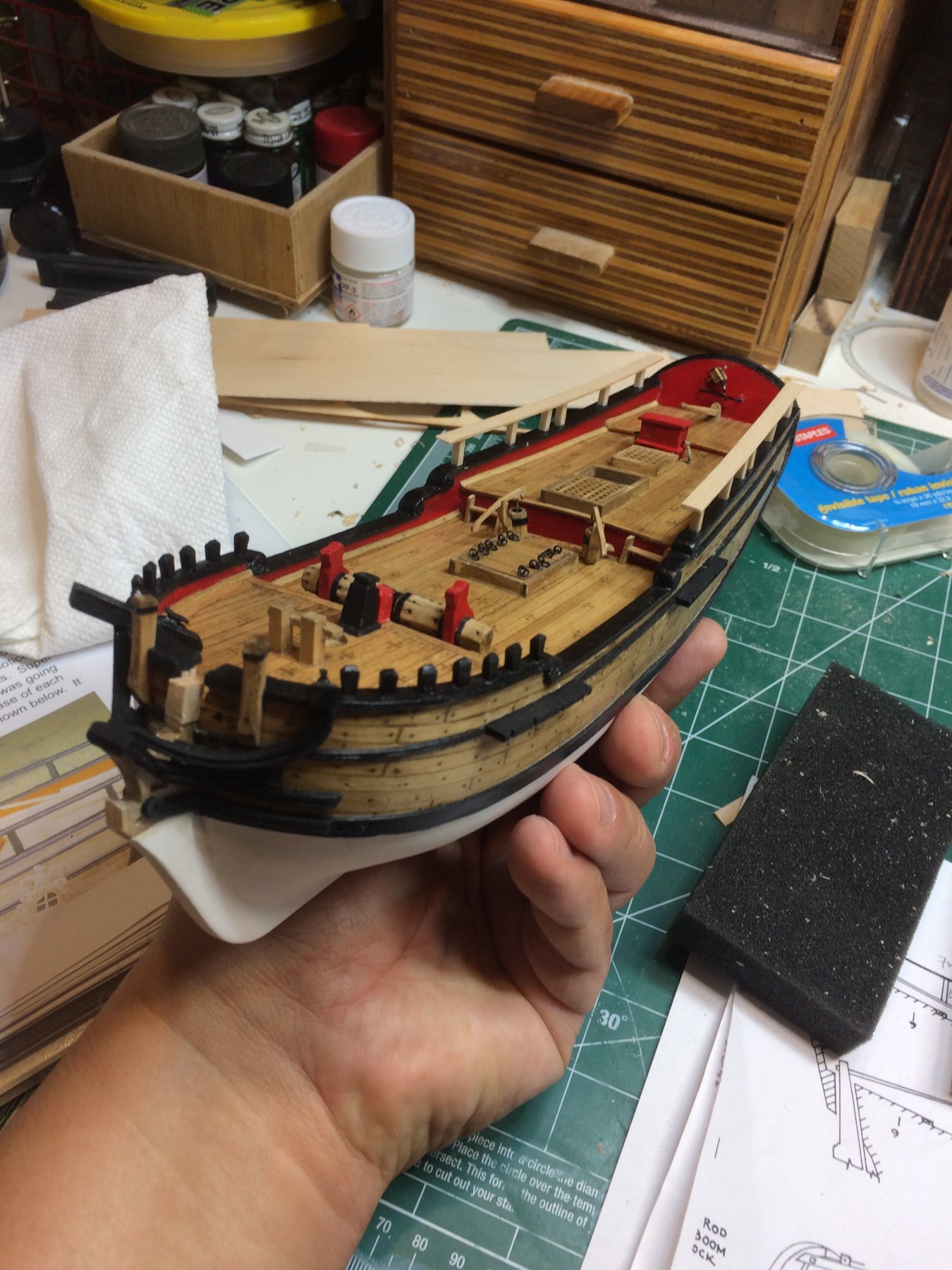
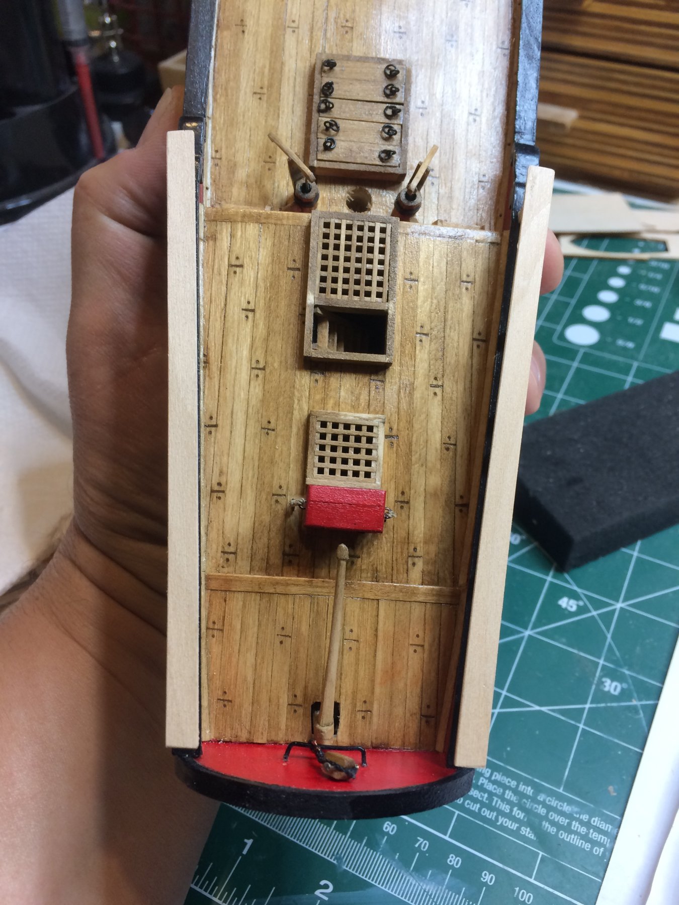
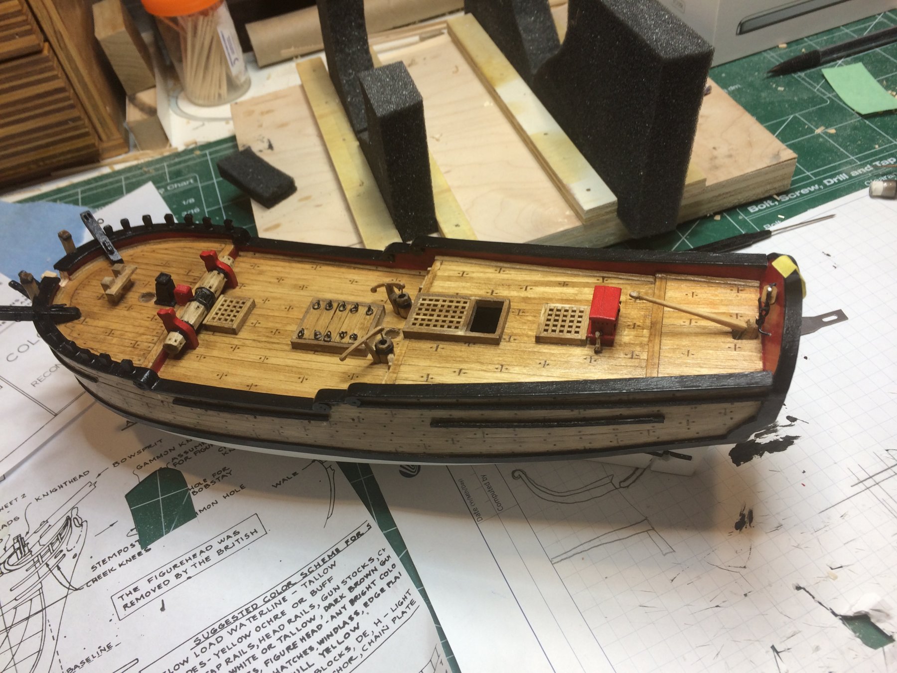
Swivel gun stock installation have been completed. I made a small notch on the stocks rather than cutting the molding so the stocks can fit as close as possible to the ship hull.
Glue them into position. The last two stocks, closest to the stern will be done after i complete the quarter badges..
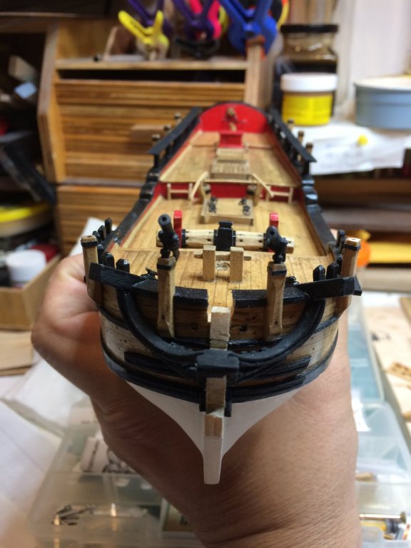


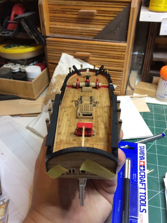

and a testing...

Happy modeling.
- Fright, russ, Ryland Craze and 3 others
-
6
-
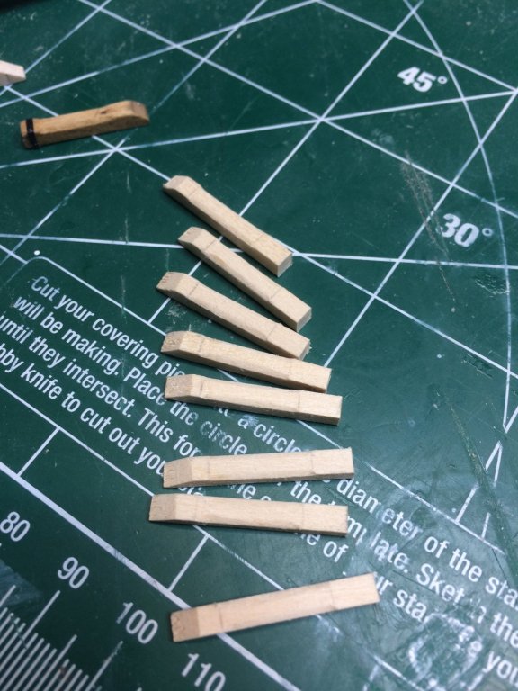
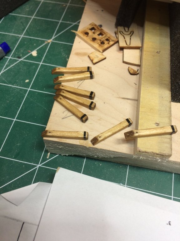
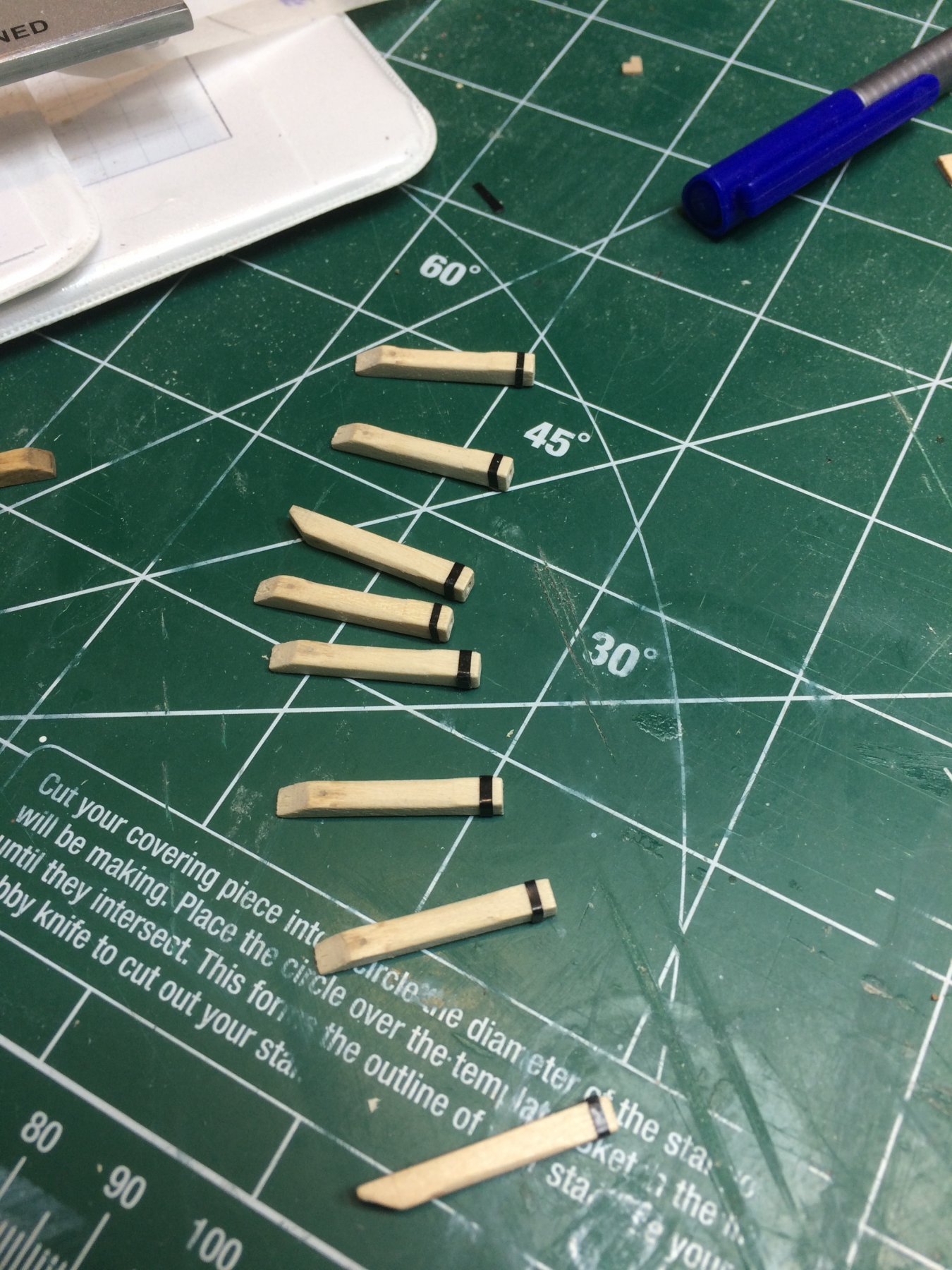
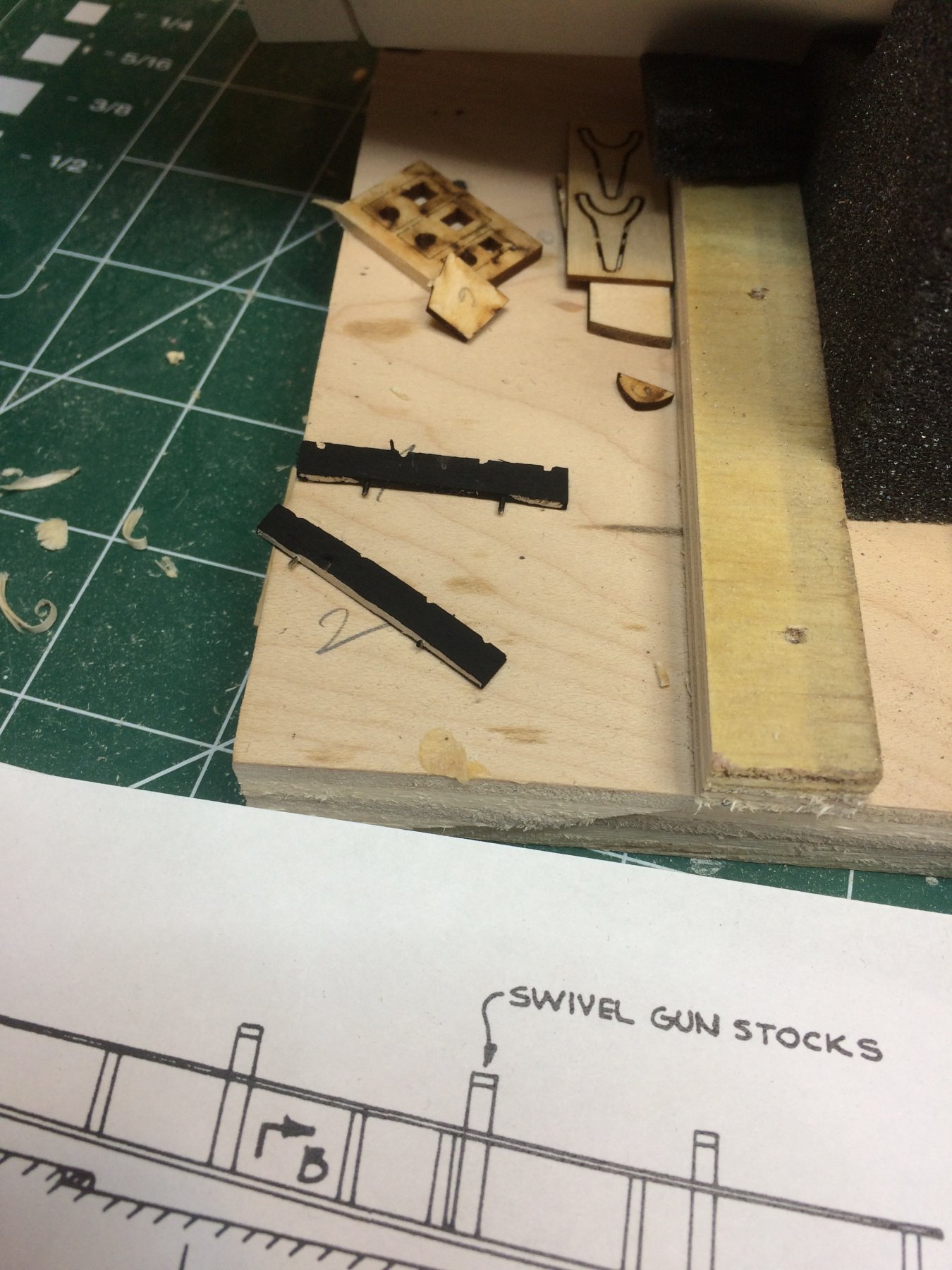
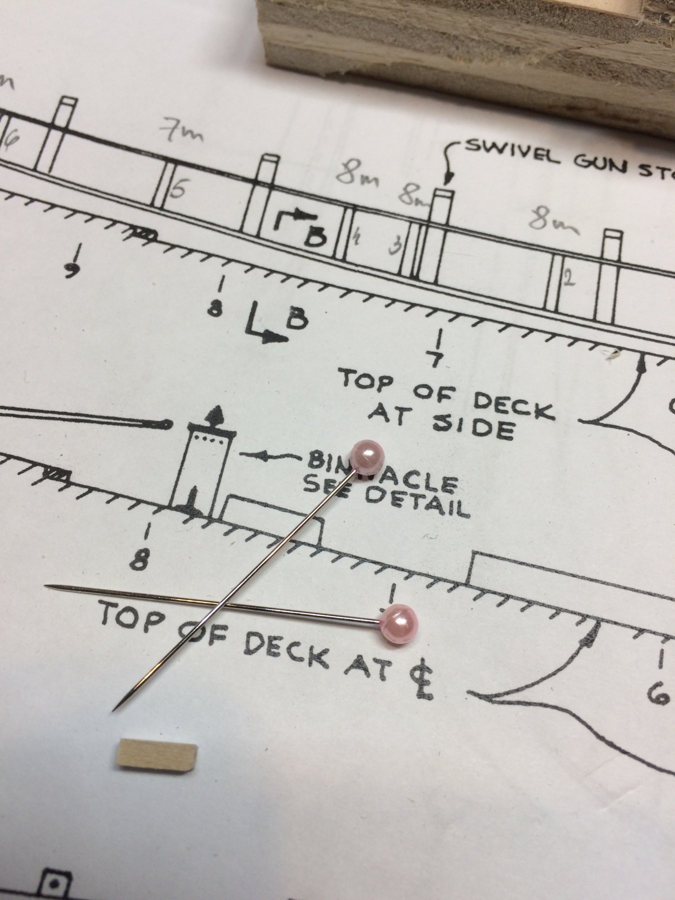
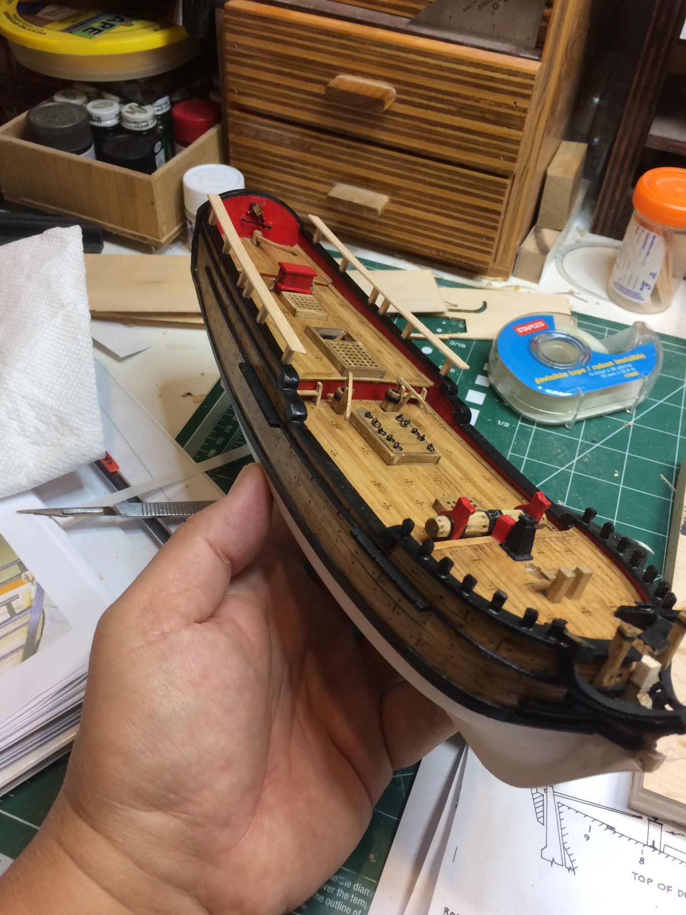
Swivel guns stocks were my small project for today. Well small project, 8 of then for 2 hrs...
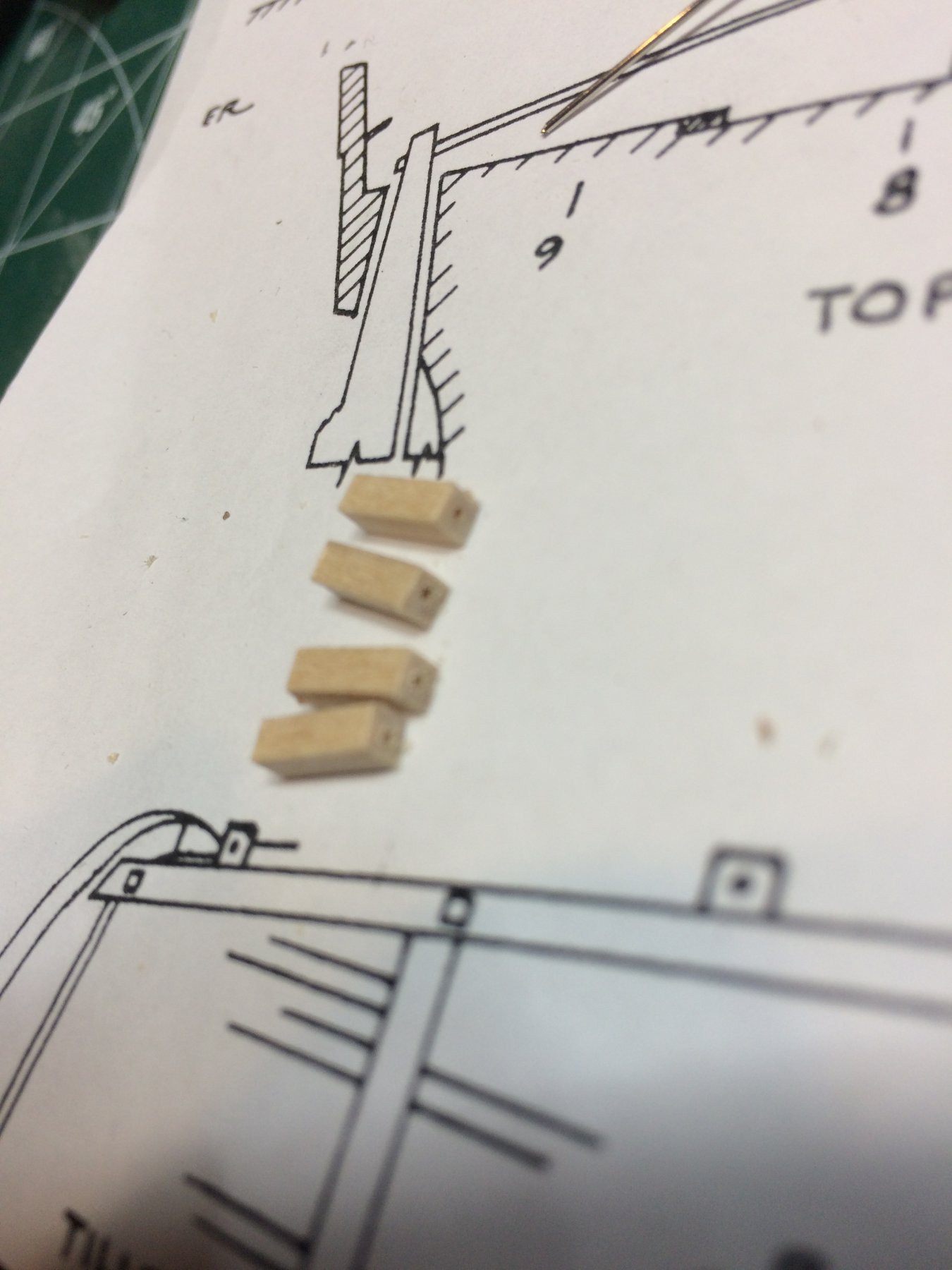
Made from 3.5mm x 3.5mm basswood, milled on my mini table saw. They have made in the same way as two stocks at the bow, except they were longer. Unfortunately i made 8 of them but i need two more so tomorrow will continue building them and mounting to the ship.
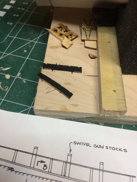
The length of the stocks were taken from the plan, cut to size, shaped, two outside edges were carved a bit to give more details. To simulating a iron band strip, i used electric tape cut to the size and wrapped around the top of stocks. I used tiny drip of a glue to fasten the tape to the stocks.
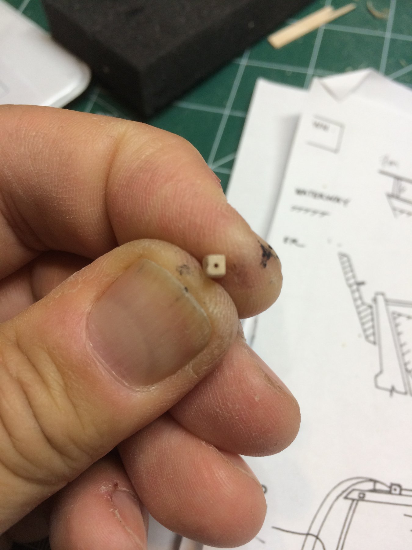
The small hole was drilled on the top that will be accepting swivel guns.
To mount them to the ship i have to decide either to notch the molding or stocks so they can fit on the ship...
Cut to shape and two outside edge slightly carved for more details..
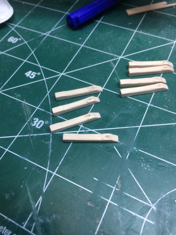
Small hole was drilled on each one and filled with wood filer to simulate wooden pins...
Iron band simulated....

And short bath in stain...
Happy modeling..
-
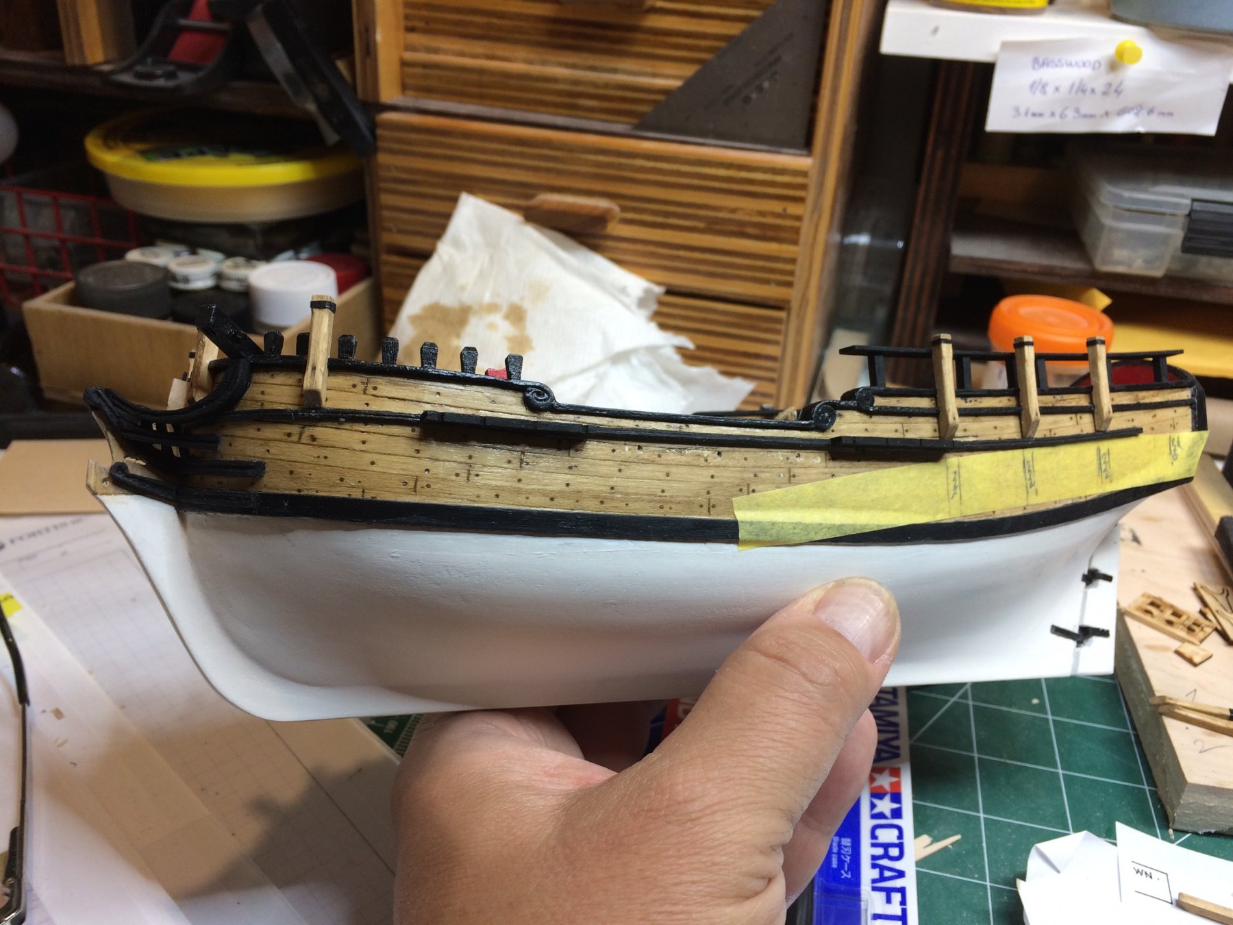
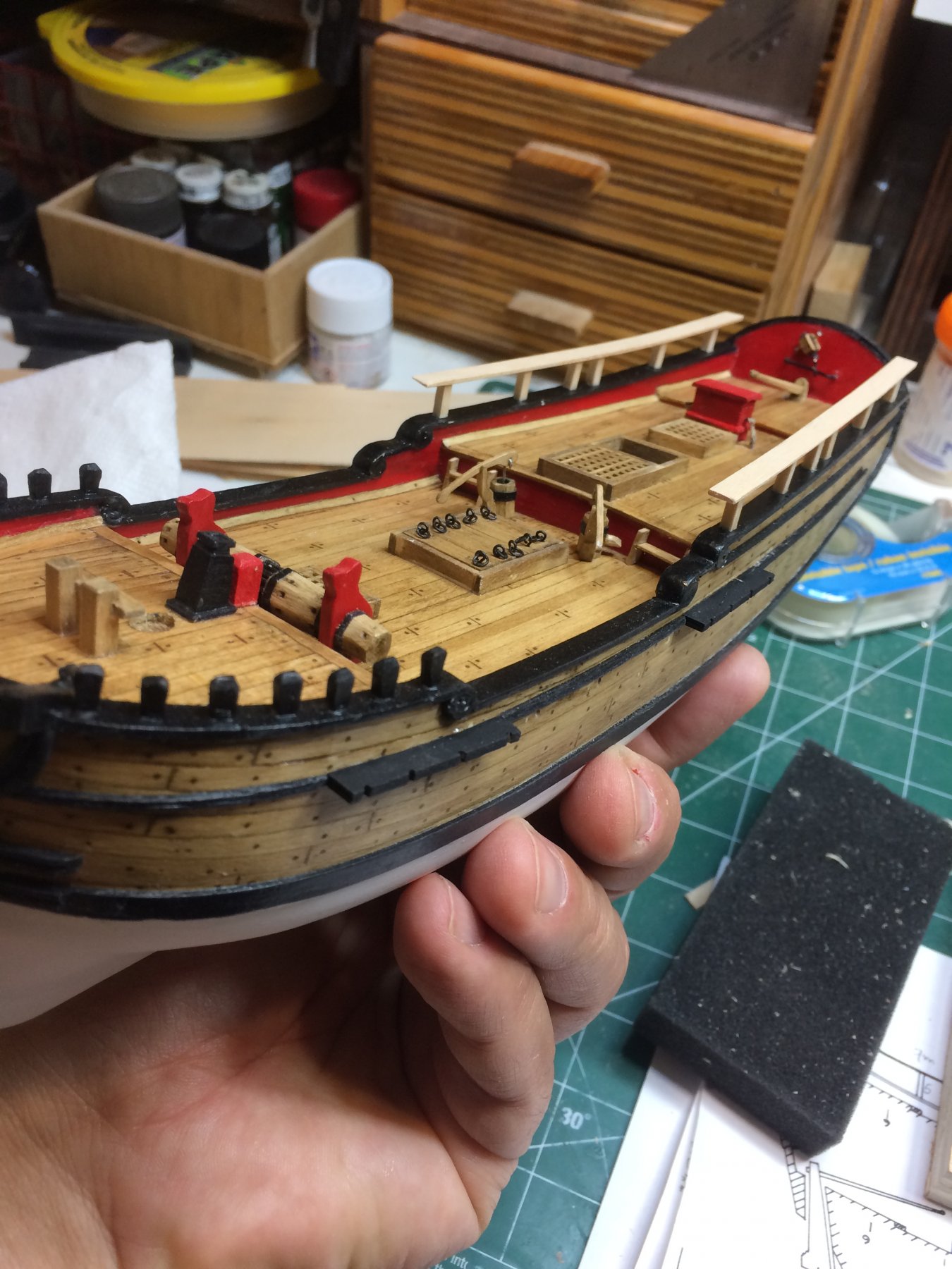
Another layer of white color applied to ship boat and a layer of black color applied to poop rails. The layer of varnish have to be added to the recently painted parts including poop rails..
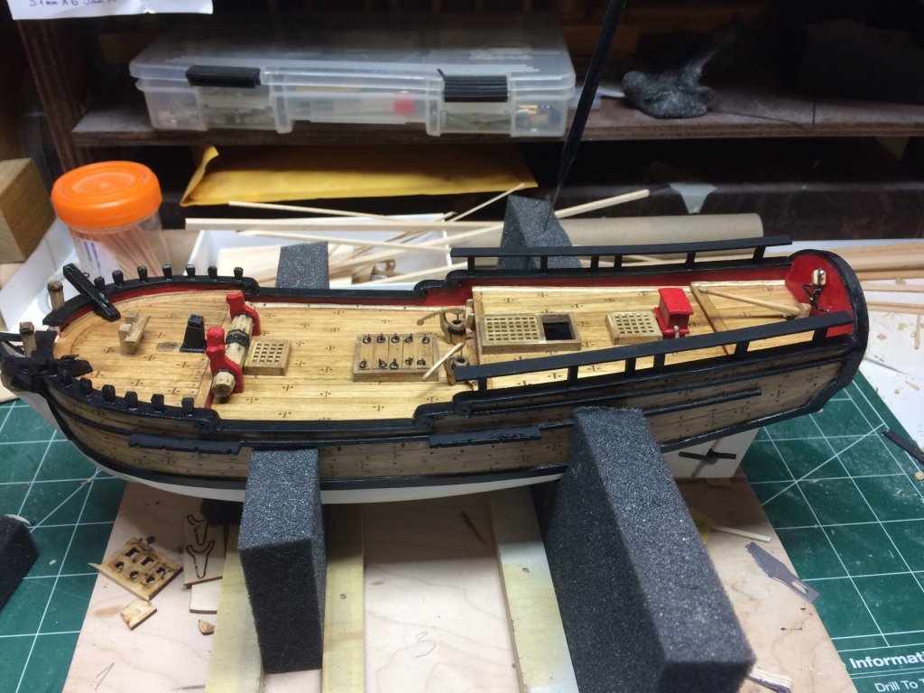
This little ship becomes to look very interesting i must admit...
Next, the deadeyes are on the building menu, swivel guns stocks along the quarter deck rail and quarter badges... The badges will be very interesting; have not done any parts like this so have not decided to go either with wood or with sculpey..
Happy modeling..
-
5 hours ago, lmagna said:
WOW
She is really coming together and starting to show the results of the constant attention to detail you have been using throughout the build. No one would suspect her origins as a simple semi formed block of wood anymore.
Thanks Lou, appreciated. I must admit that following Chuck's practicum really did make a difference; just going by the kit plan it would be fairy difficult to achieve acceptable results.
Thanks for following..
Cheers.
-
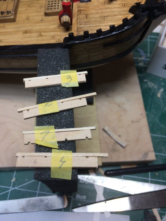
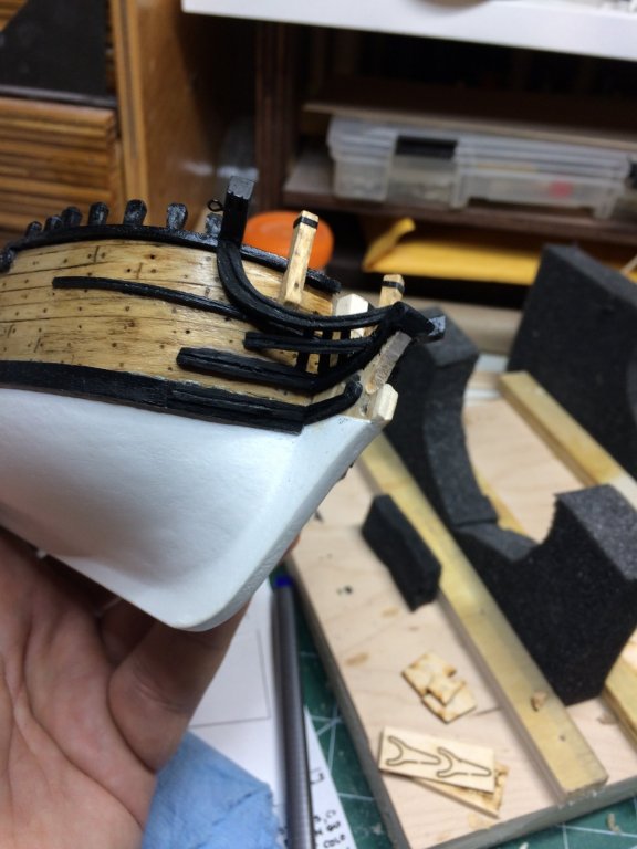
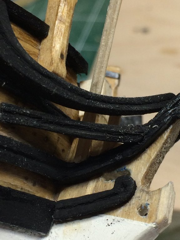
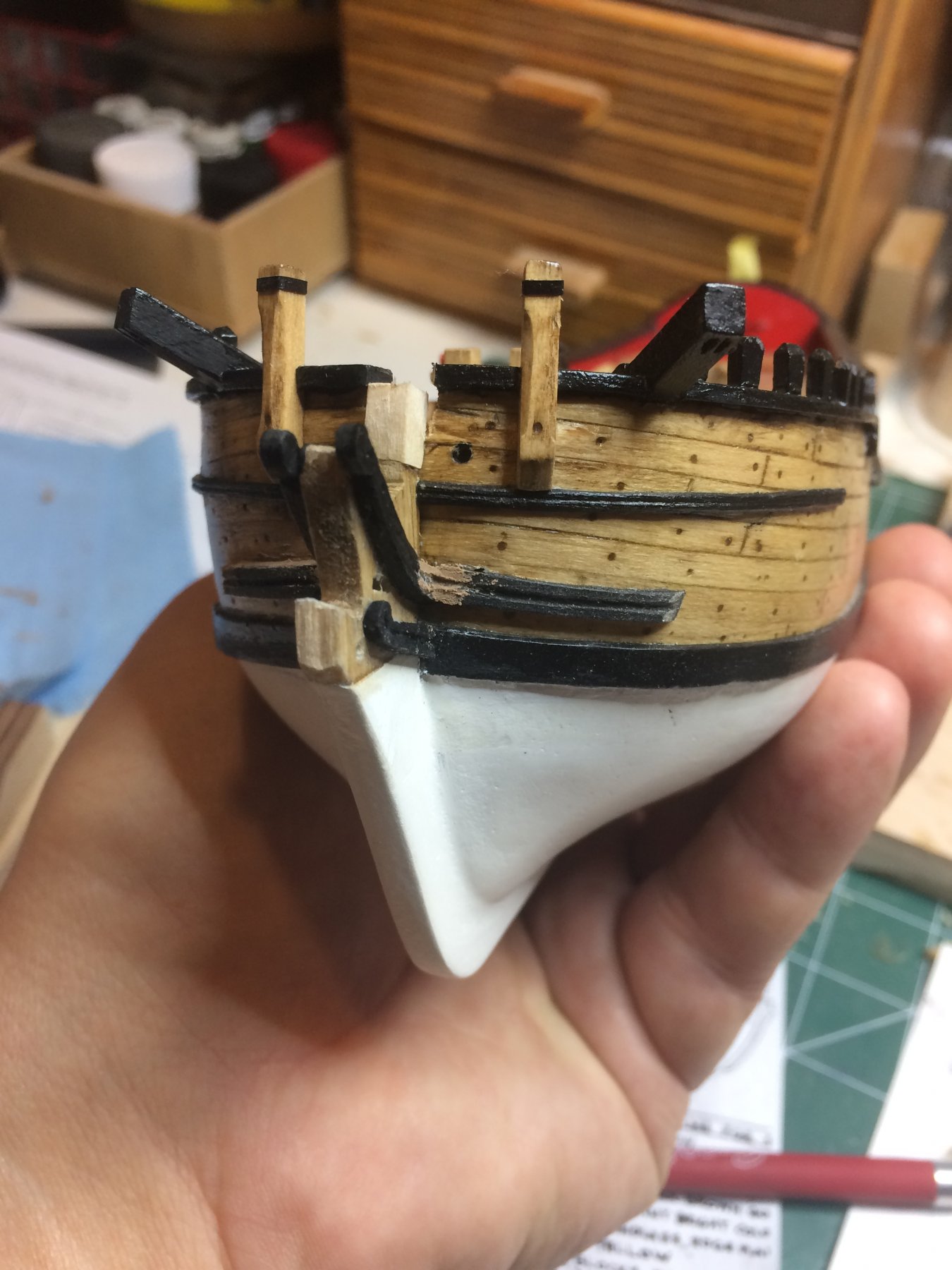
Work on channels continued today. It might be a bit of an overkill but i have decided to put a two small nails in the back of the channels; this should provide an extra strength to keep channels on the ship, safely mounted.
Not sure if this is needed but these small items can be broken very easily and then it will be too late. So i marked a hole with a small needle, then with 0.6 bits drilled two pilot holes.
I used sewing pin for a dowel, inserted in one hole, cut to appr 2mm length, inserted to another hole and cut to the length. Then i lean it on the ship allowing pin to leave a mark on the ship planking. Then using the same drill bit size, i drilled a hole in the plank. Run a layer of a glue and mount channels.... Since i marked them all with numbers (1-4) and black color, for some reason covered the pencil mark 😁, i let them dry on correct numbers...
The final front molding will be installed after deadeyes are installed..
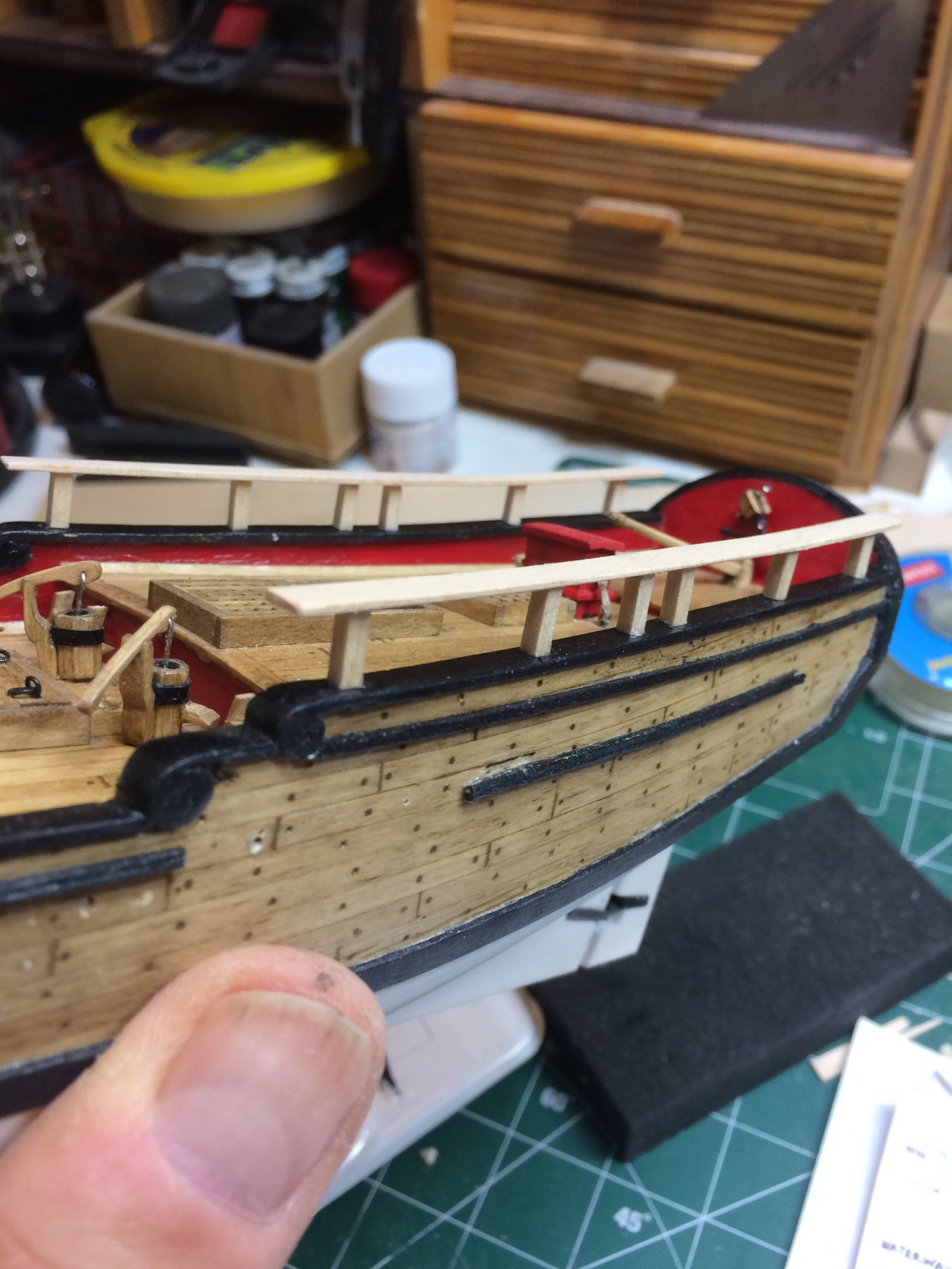
Then i started to work on poop rails.
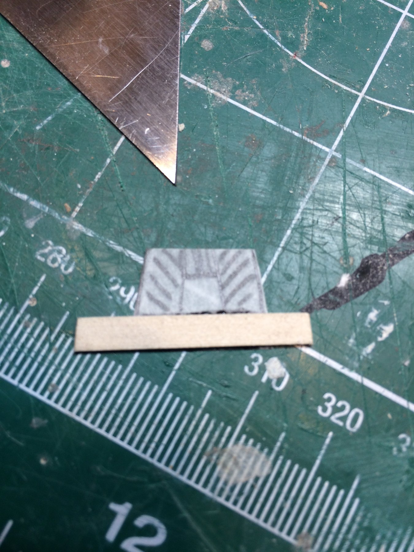
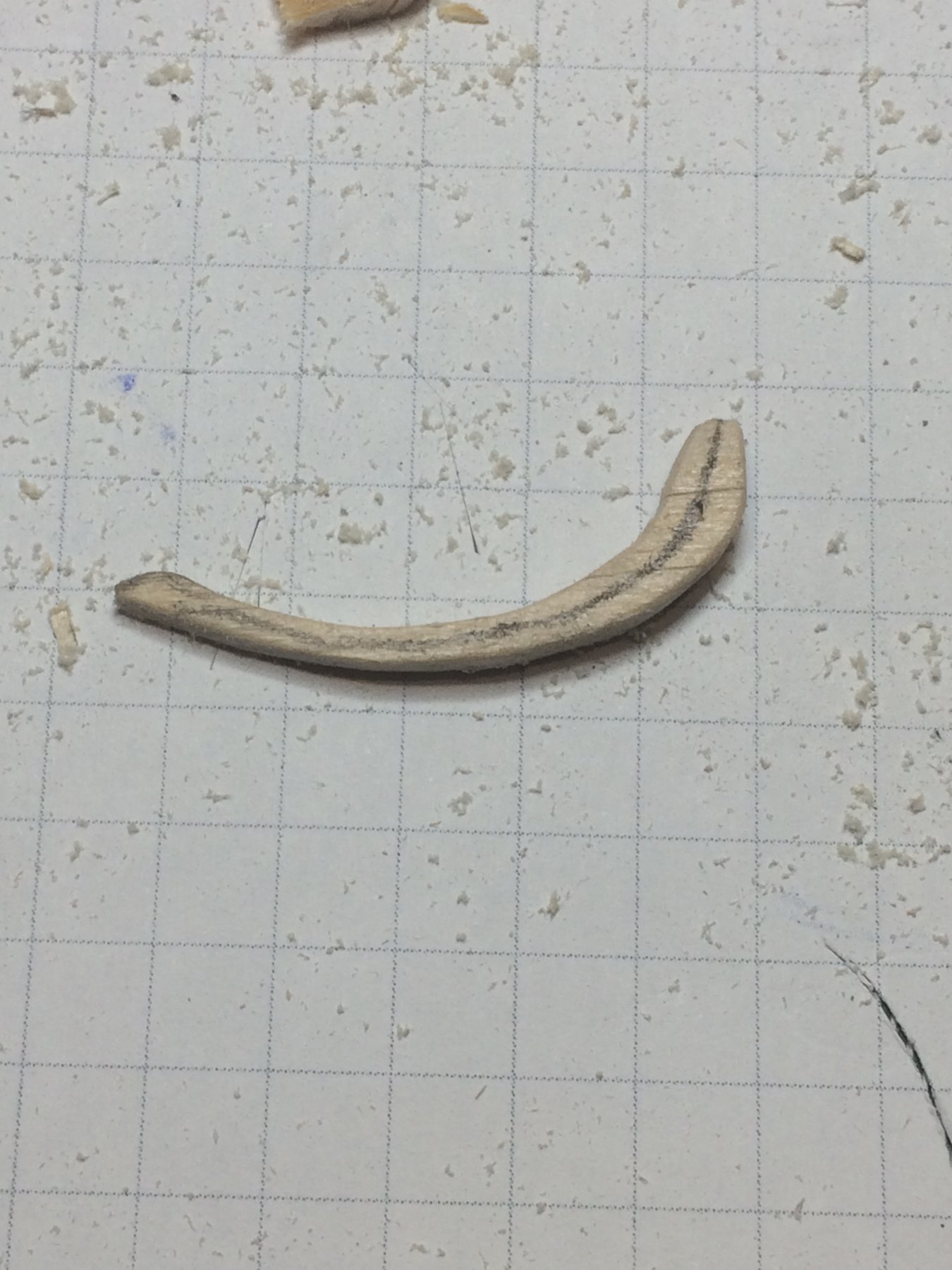
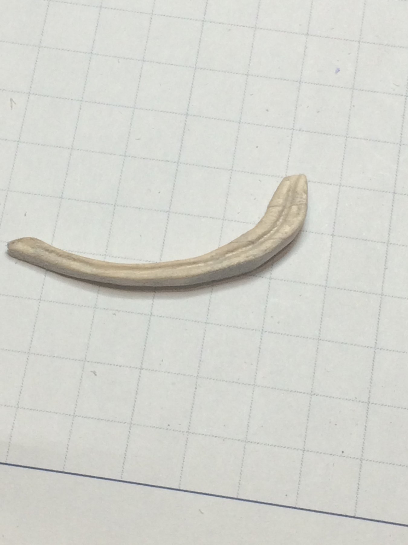
First, i made a cap for a rail, out of a basswood, 0.6mm thick. The shape was traced from the top of the bulwark. The edges were sanded with sandpaper to make them rounded.
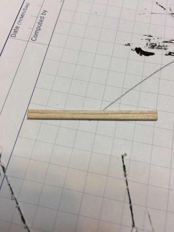
After completing the cap for the rail, i started building the rail stanchions. 2mm x 2mm basswood was used. I measured all 7 stanchions for each side, from the plan. They are different in size, getting shorter towards the stern and they do have a slight taper on them.
These stanchions are delicate pieces and some reinforcement has to be in place.. Back to trusty sewing pins...

... which will be placed to the bottom of each stanchion. Pilot hole squeezed in with a needle and hole drilled with a 0.6mm bit...


Stanchion positions were traced from the plan to a piece of transparent paper and a mark was made on bulwarks with a small pin. The pilot hole was drilled for stanchion dowels (or pins)..
After drilling stanchions are mounted, from the mid ship towards the stern making sure they stay straight on bulwark. I did a test run first to make sure all of these will be sitting correctly; after that i glue stanchions permanently..

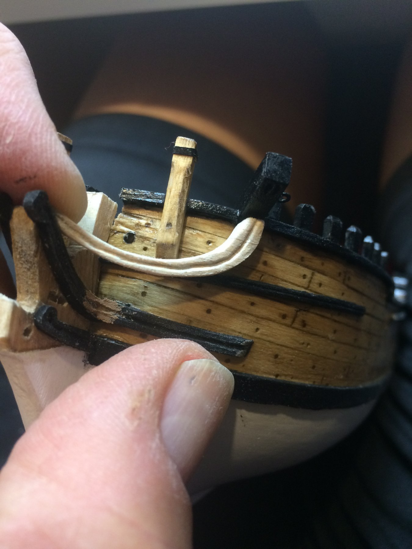
Both sides completed...
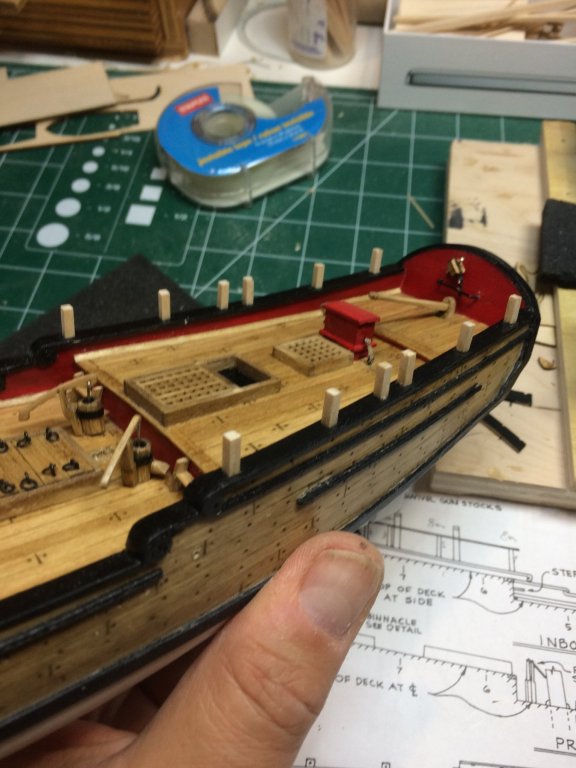
Then i put a rail on them; some sanding is needed to have cap rail sitting flash on stanchions. I was contemplating using pins for rails as well but decided to follow Chuck's suggestion that super glue will be enough to keep rails to the stanchions..
.thumb.JPG.e2141fa2b6955d6e2f0a728be1b5fe9a.JPG)
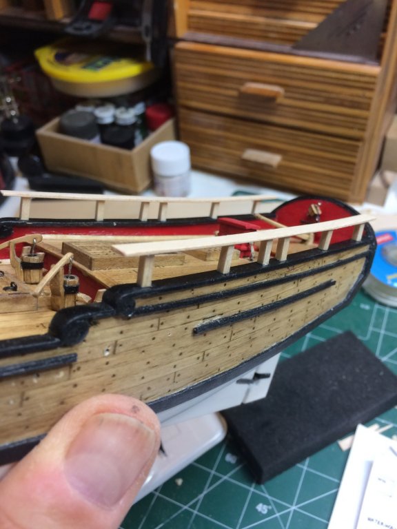
After that i glued channels on the ship as well..

All done...


Next is a layer of black color...
Happy modeling..
- jct, russ and GrandpaPhil
-
3
-
Another layer of white paint applied to the ship boat; small boat that takes me more time to clean the brush than to run a layer of paint 🙂
Waiting for paint to dry i decided to continue following Chuck' practicum by building a channels (and moldings) for deadeyes.
First i marked channels with numbers on the spare copy of plan. BTW i usually make few extra copies of plan so i can cut, trace, leave a paint mark on it without damaging the original plan. Original plan is actually on the wall in whole size...
The channels will be made out of 5mm x 1.5mm basswood, shaped to follow the ship shape. On the outer side of each channel i will mount a beaded molding so total size of both pieces should be kept in mind - not to extend the size that is on the plan.
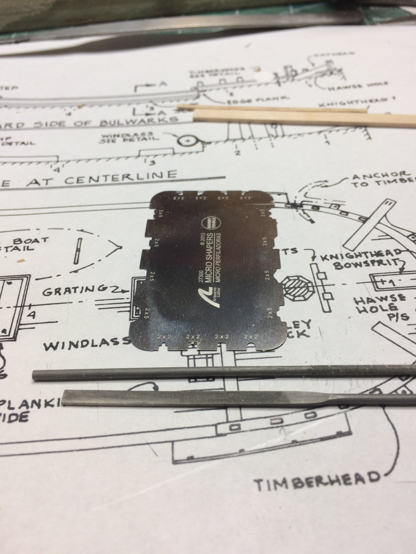
Once channels are cut in size and measured against ship, using a AL scraper, i cut small molding profile on each end of channels. This will match the shape of the molding once glued to the channel.
Beaded molding is scraped from basswood, same width as channels, in one long piece that was cut to the size of each individual channel.
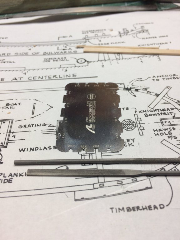
I carved a little notches on the outside edge of each channel; these notches will be used to hold four deadeyes. The correct size/depth of notches was accomplished by small needle file that is square in shape. Next task will be to paint channels in black and glue to the ship..
New AL scraper in use and square needle file used for notches.
All four channels and moldings ready for painting..
Happy modeling.
- lmagna, John Allen, ccoyle and 1 other
-
4
-
Continue with boat work.
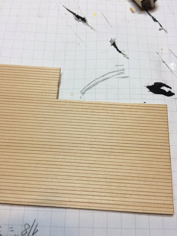
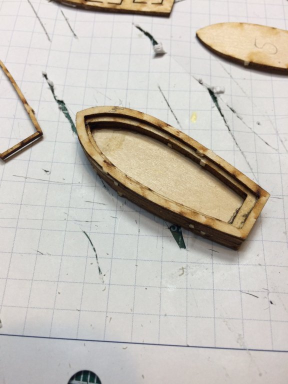
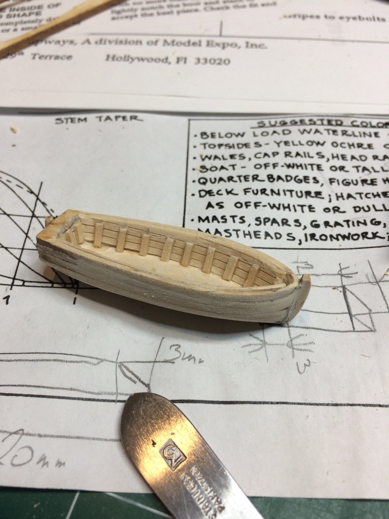
Added floor bottom made out of .5mm planks. Was very difficult to make them symmetric on both sides of imaginary middle line... 5 boards were cut and sanded to the correct size ans shape, small space between planks were left as well.
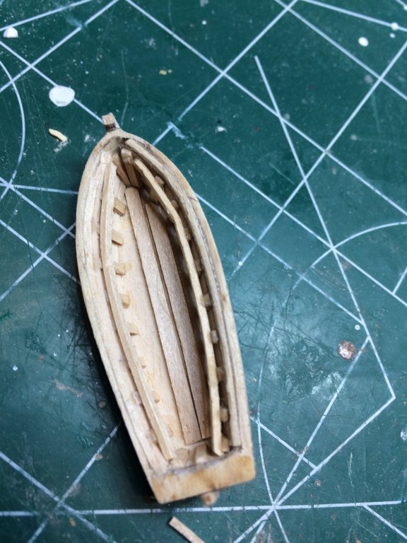
Then a added a raiser that is glued across the frames.
The seats are added next and this part of building process was kind of interesting. First i made all seats a bit oversized...
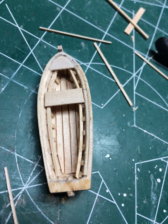
So not being able to find correct size, i ended up with some older way of doing stuff.
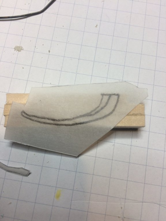
First i turned the boat upside down and traced the shape into piece of transparent paper. Then accommodating dimensions of boat interior since seat will be mounted on raiser, i draw another two lines representing position of the raiser. After that i marked all sits and cut them from the paper.
The seats in stern area were glued to the transparent paper. The idea was to glue them all to the paper and cut all in one piece and glue to the boat. This way i don't have to deal with 4 small pieces separately. The final trimming was done before mounting.

So the end result is like this..
And a bit of sanding with different sand paper sizes..
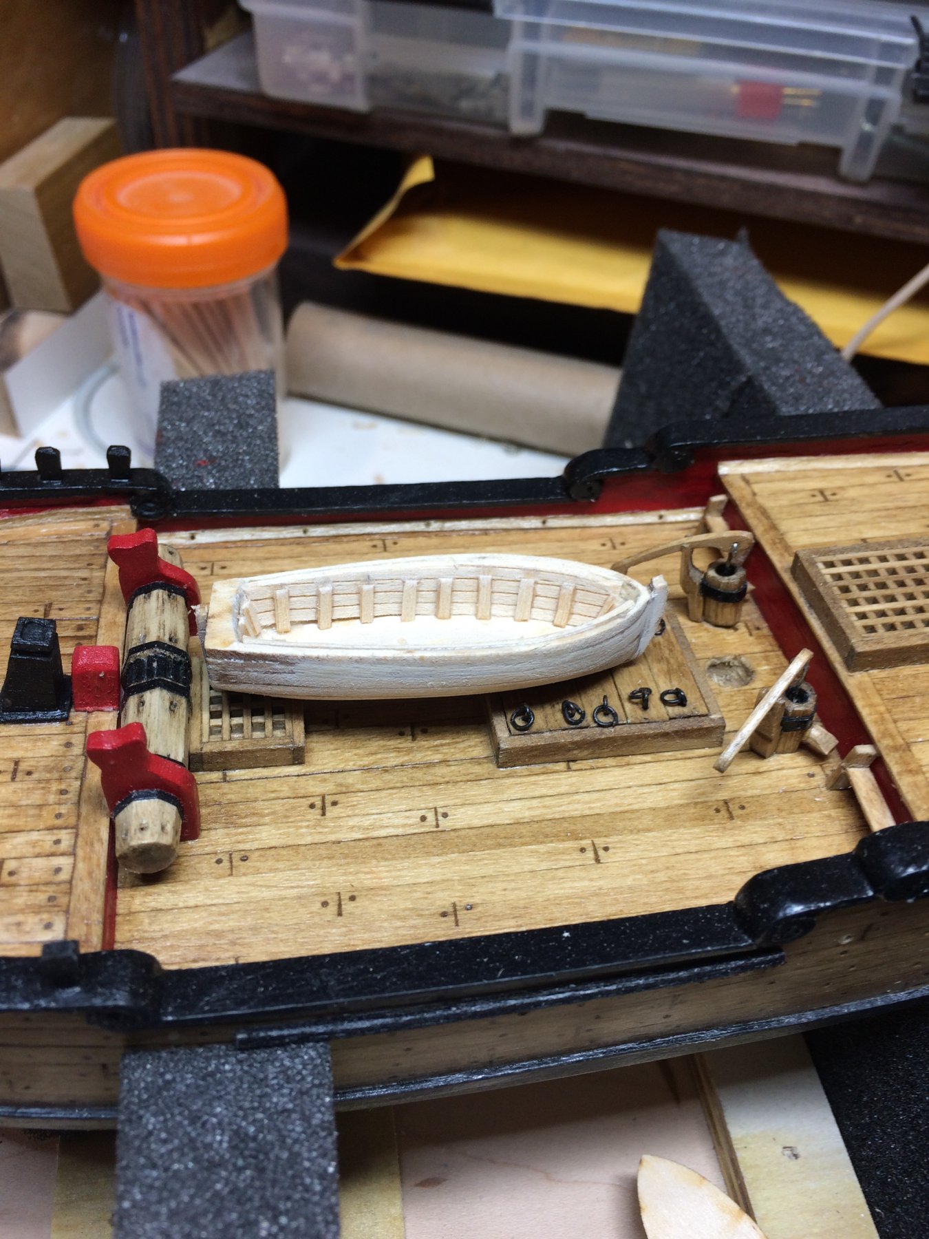
.. and have it ready for painting in white. For this i will try to mimic Chuck's color schema...
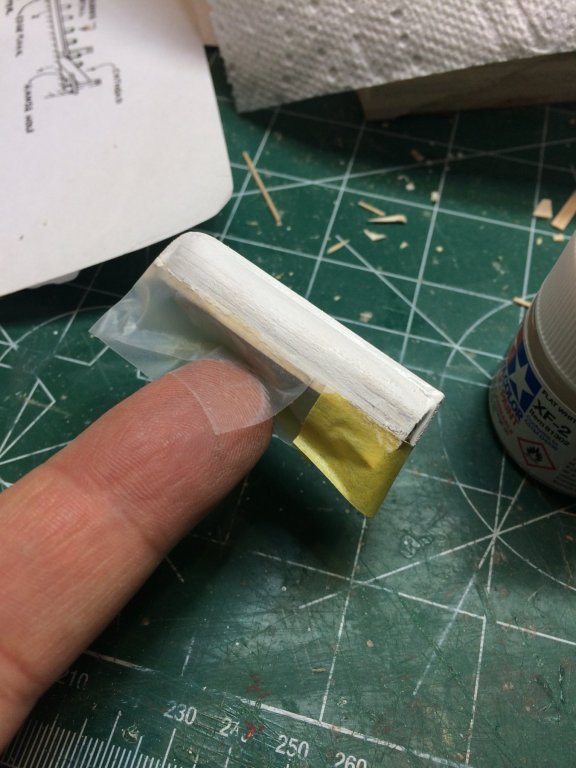
It would probably take few layers of tinned white Tamiya acrylic color...
Happy modeling.
- jct, GrandpaPhil, lmagna and 2 others
-
5
-
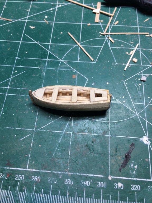
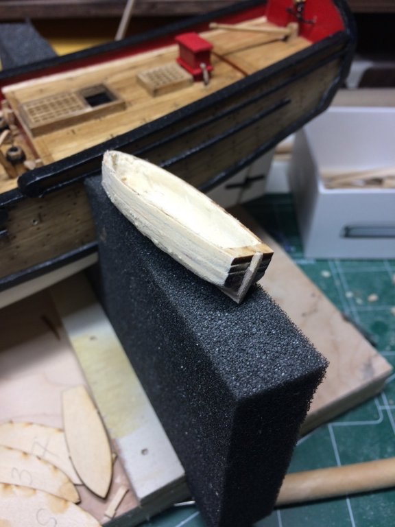
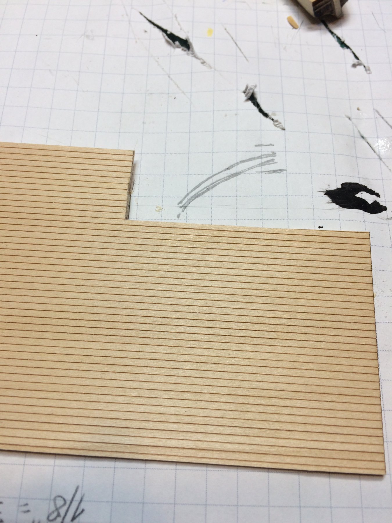
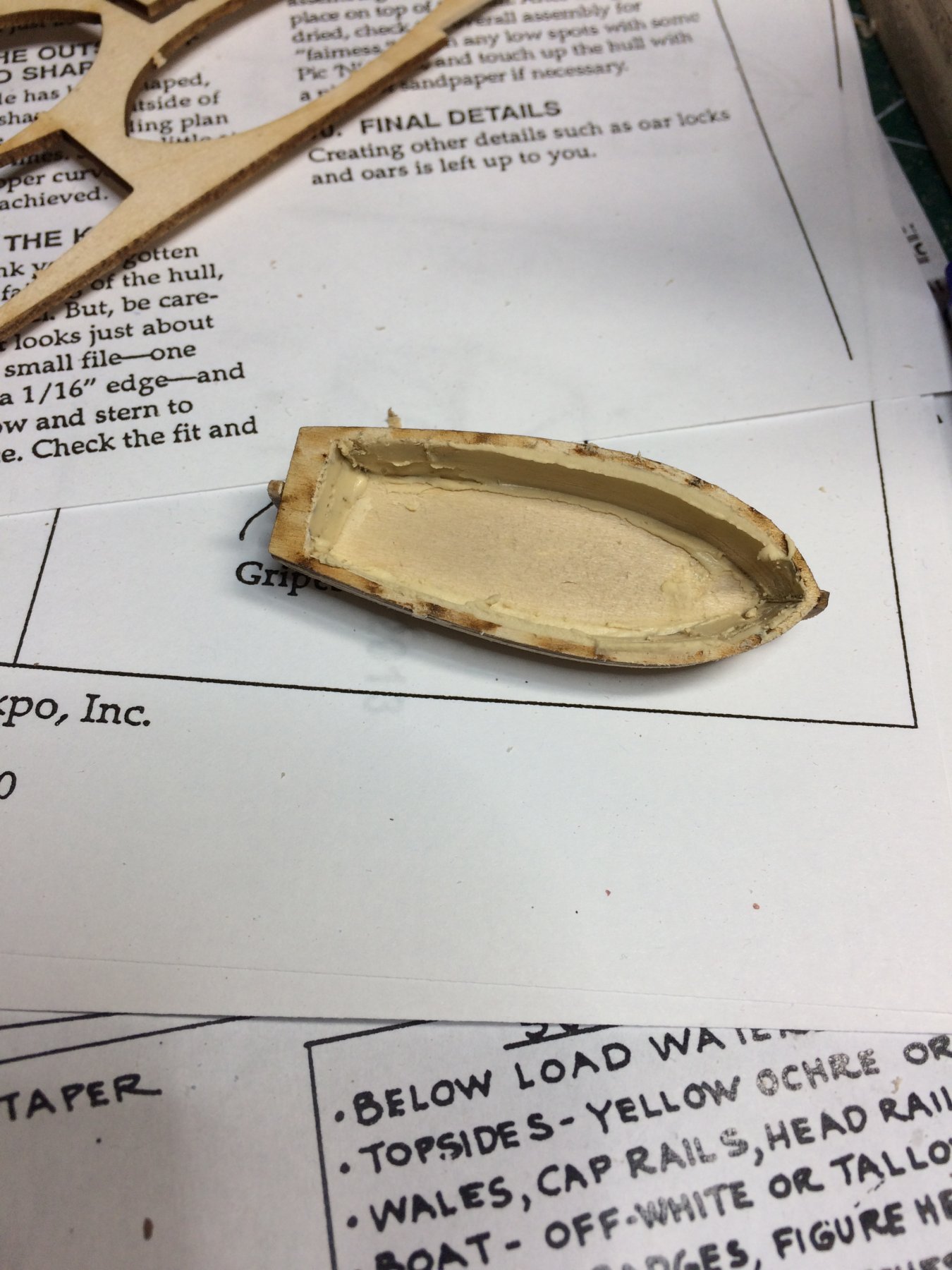
A bit of a work done on ship boat; sanded inside and outside. I did not like inside part; too much wood filler was visible so i decided to run a layer of planking on the inside. Not sure if this is historically correct but at the end will look much better than with filler. Planks i used are included in the kit and most likely they were meant for deck planking.
I cut proper length and the width was 5 planks. Dropped into water bath for few minutes and dried with towel. Still wet i glued it to boat interior. Then i cut excess that was raising above the boat.
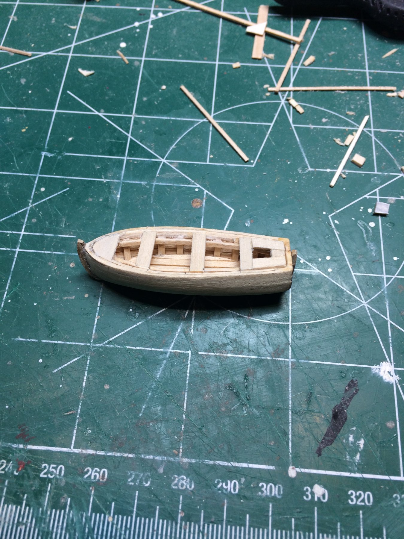
The frames were cut and glued along side of the boat.
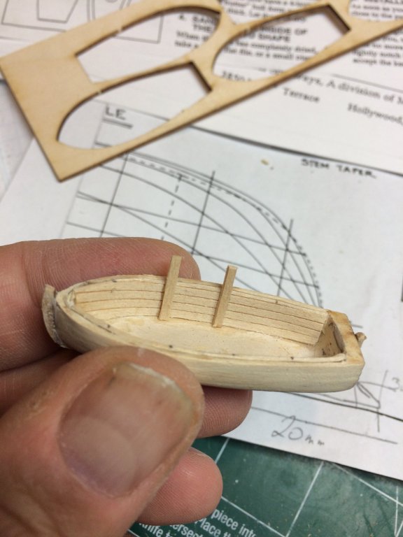

Finished it for today and could not resist not to test it on the ship...

The light was very bright and color is off; no white color inside..
Happy modeling.
- jct, GrandpaPhil, lmagna and 1 other
-
4
-
Finished up head rail area, sanded, cleaned and painted in flat black. Next will do protective varnish layer...
I am actually very glad that this part was completed; the small scale of this ship part made it somehow difficult to get it right (well there is still room for improvement) and decent amount of wood filler was used to cover some imperfections during building process.
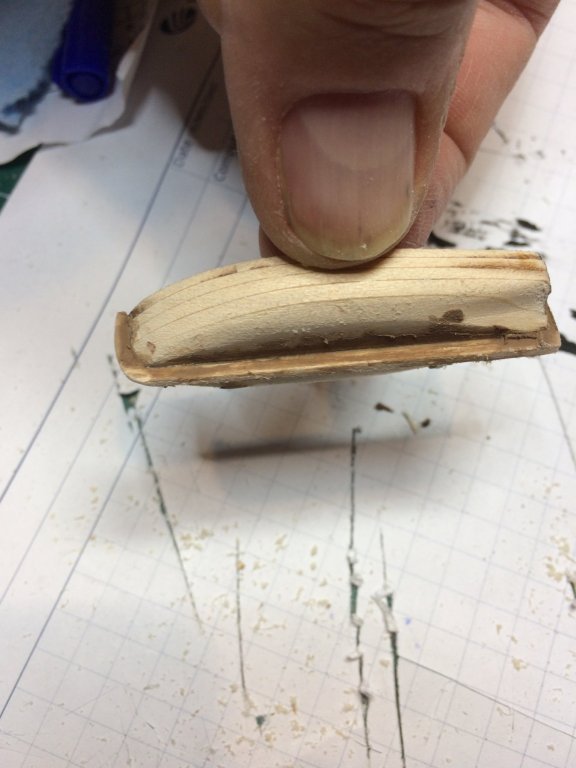
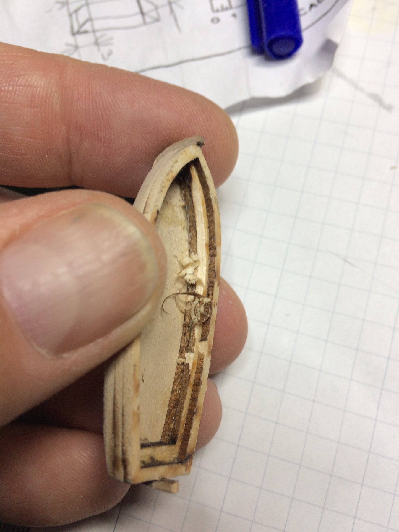
After this, work on ship boat continued with carving inside of the boat using different carving knives and a round file positioning it in such a way that top of the file was facing down, inside of the boat and with left-right movement was able to file most of interior o the boat. I had to apply a bit of wood filler which will be sanded to the final shape.
The layers are very tiny and not much wood available for carving and sanding. Sanded outside of the hull and also applied some wood filler for final sanding...


Happy modeling..
- GrandpaPhil, russ, John Allen and 2 others
-
5
-
18 minutes ago, lmagna said:
Nice work on the boat. My old kit, (The old yellow box style) didn't come with a ships boat. It looks from your work that at least this boat is build able. Not like the kits that MS sells separately.
Thanks Lou.
Yes it is buildable, i think it can be build from scratch as well but my worries were related how to get some pictures or plans to build one from scratch..
This one might turn out well..
-
I will use kit provided boat. It appears to be nicely done so no need to do it from scratch. And i don't have Sultana' ship boat plans to follow.
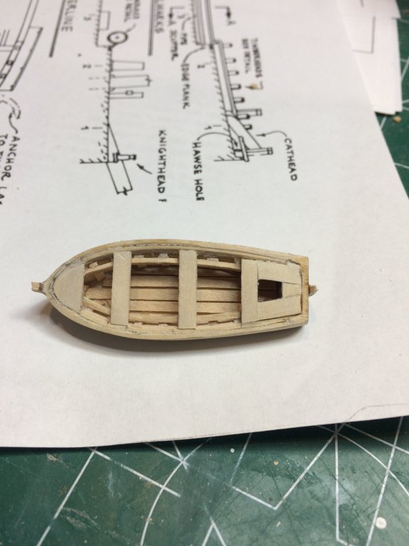
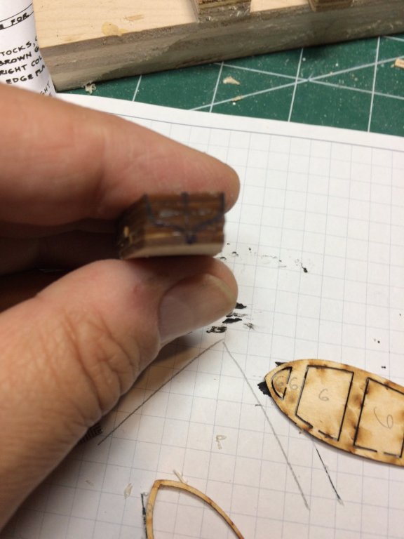
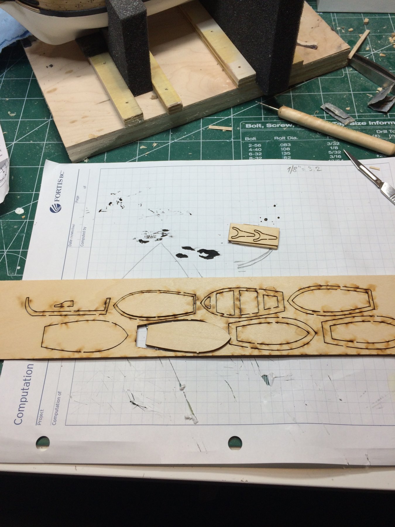
First i marked all parts on the laser cut sheet following markings provided with a kit plan. Kit includes boat building plan but i might deviate from it just because i follow Chuck' practicum. I don't think it is wrong to follow kit instruction, the end result will be similar but practicum provides more details and pictures. And someone already did a hard work on researching so why reinventing the wheels.. 🙂

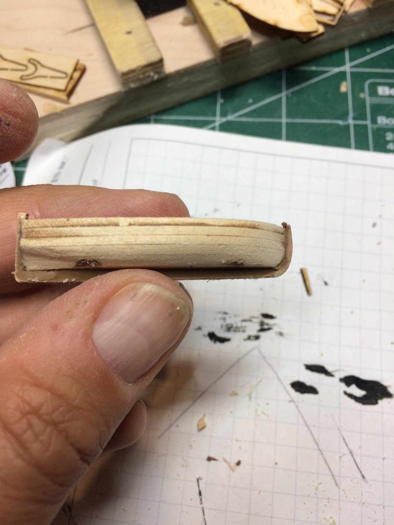
Started by gluing all six lifts together.
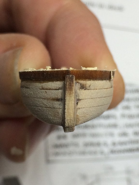
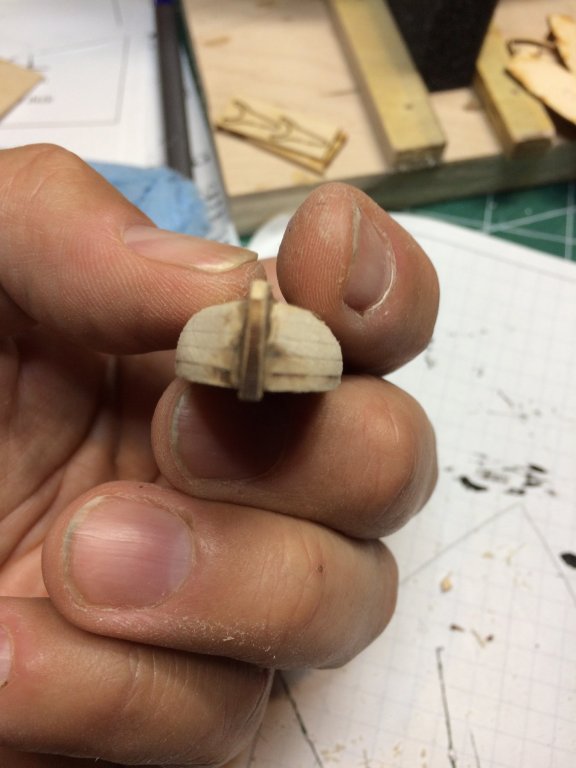
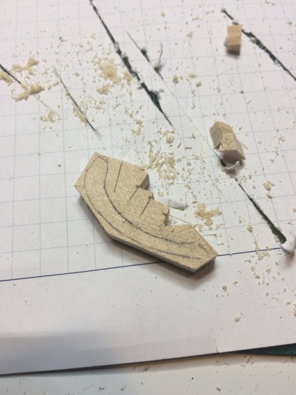
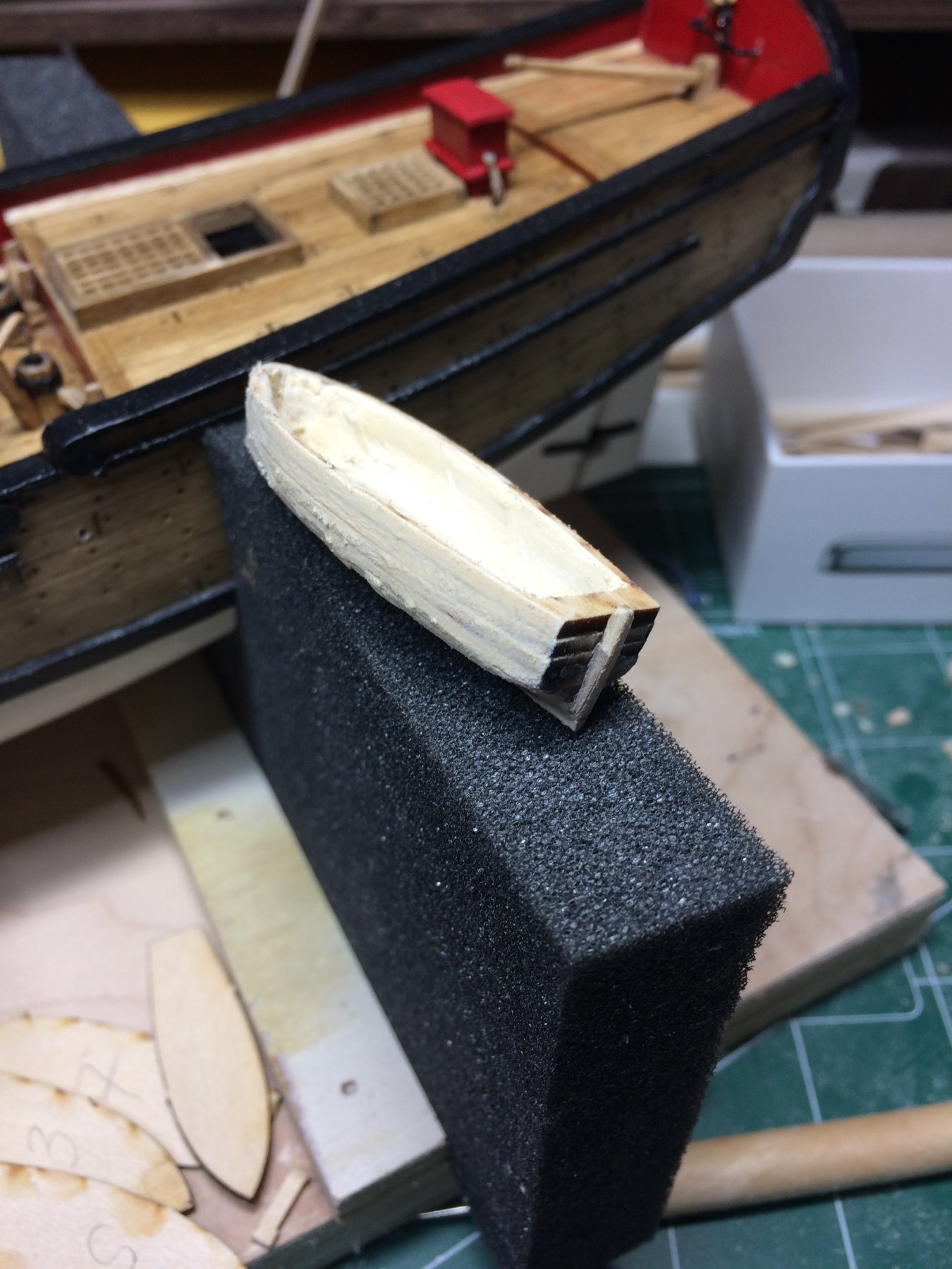
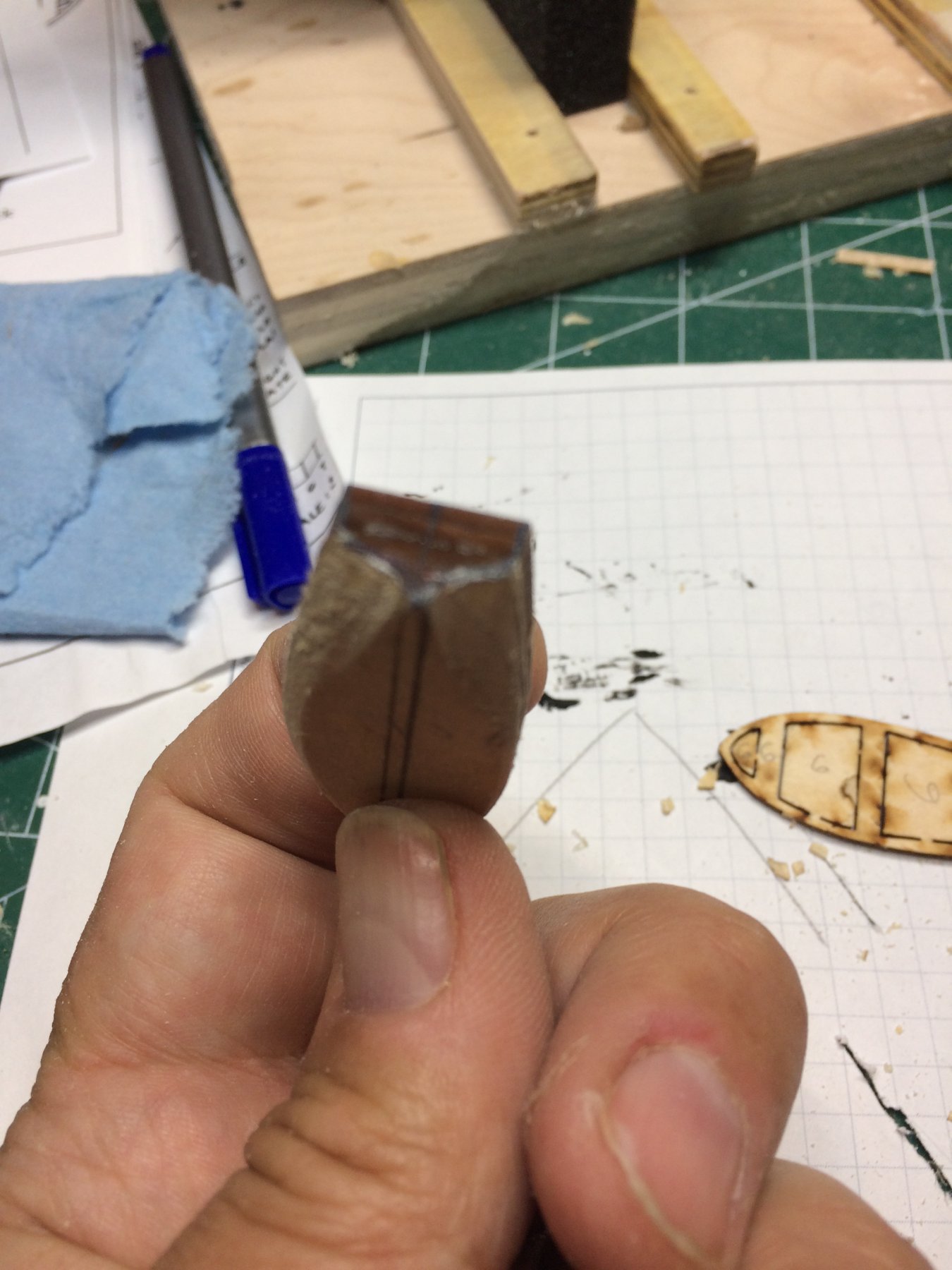
Then started to carve the hull. First marked the shape on the stern...
.. and with different sizes of sanding paper, files and carving knives managed to get decent shape. At some point started to worry that this small boat will ended up in box-like shape just because there is no much wood to carve. But at the end was not that bad.

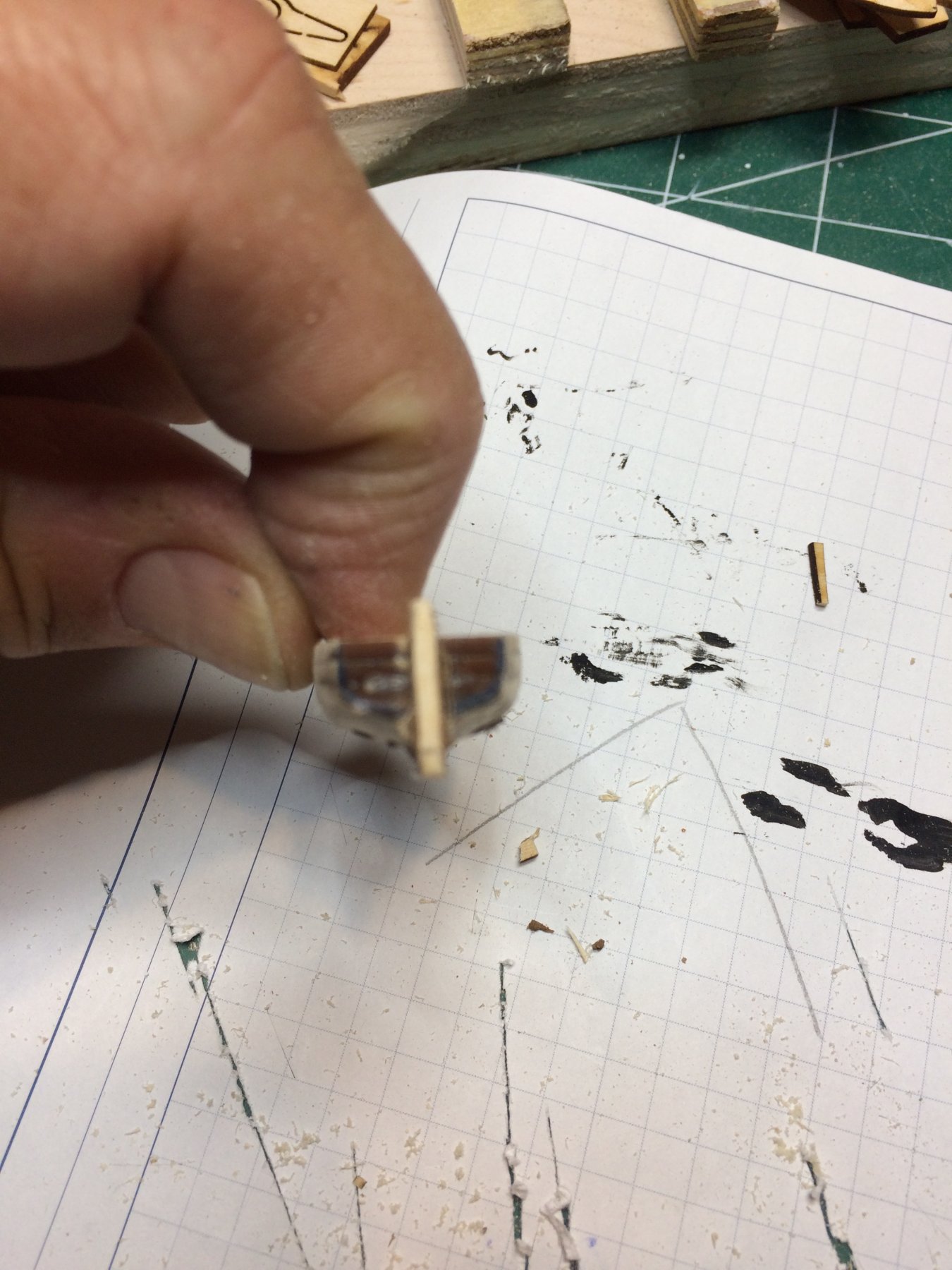
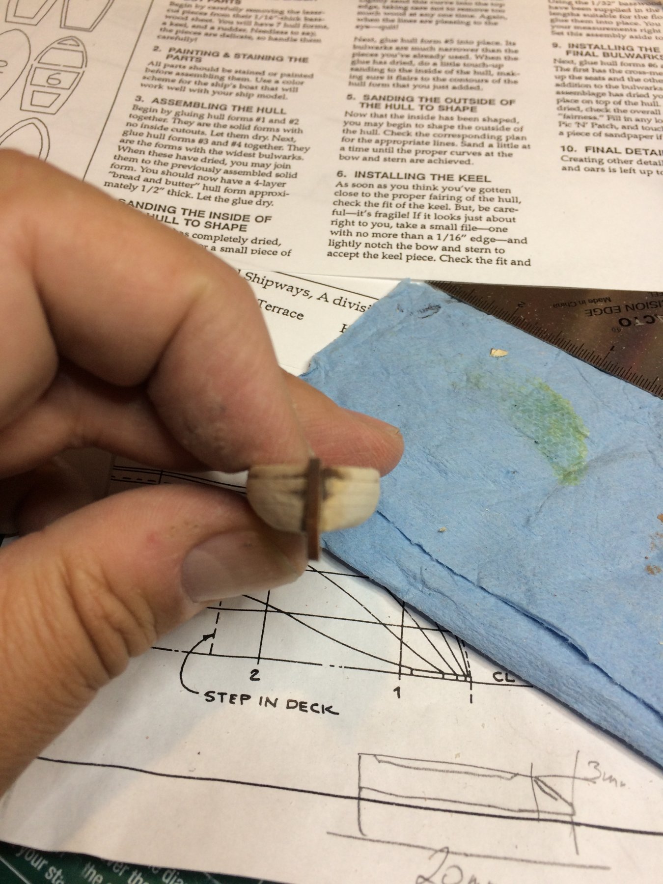
Once satisfied with boat shape i glued boat keel. The original keel that comes with laser kit sheet snapped on me so i had to make another one tracing empty spaces on the sheet where keel used to be. The sheet has plenty of extra wood that can be used for this and other purposes.. Definitely will save it for later.. The center line was marked on the ship again, since the first marking i did was removed during hull shaping process.


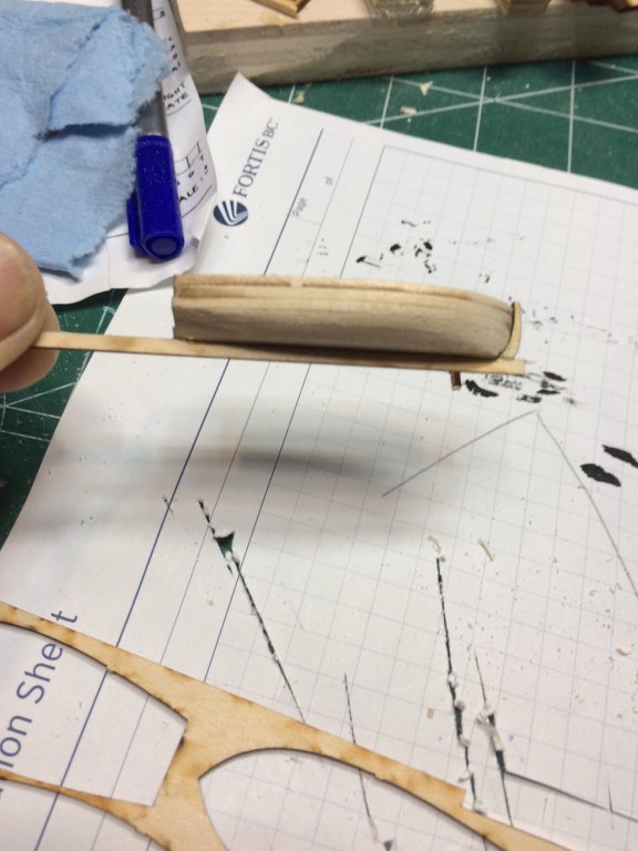
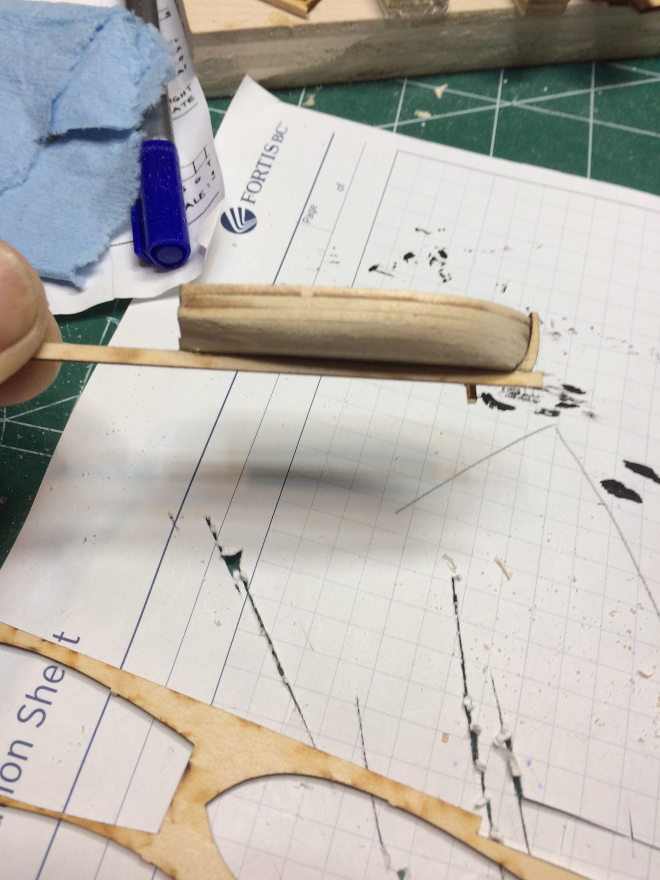
A small amount of wood filler was applied between keel and hull to make a hull more visually appealing..

More sanding will be done next to get final hull shape and continue with inside of the boat..
Happy modeling..
-
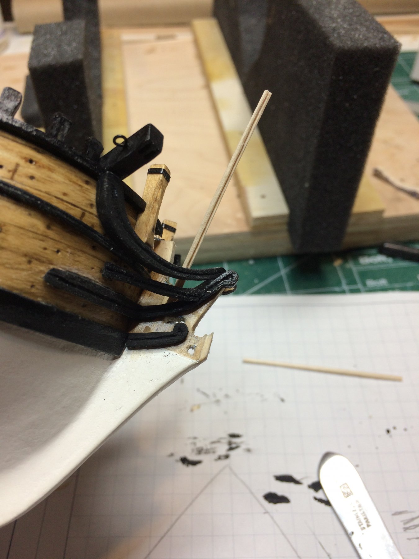
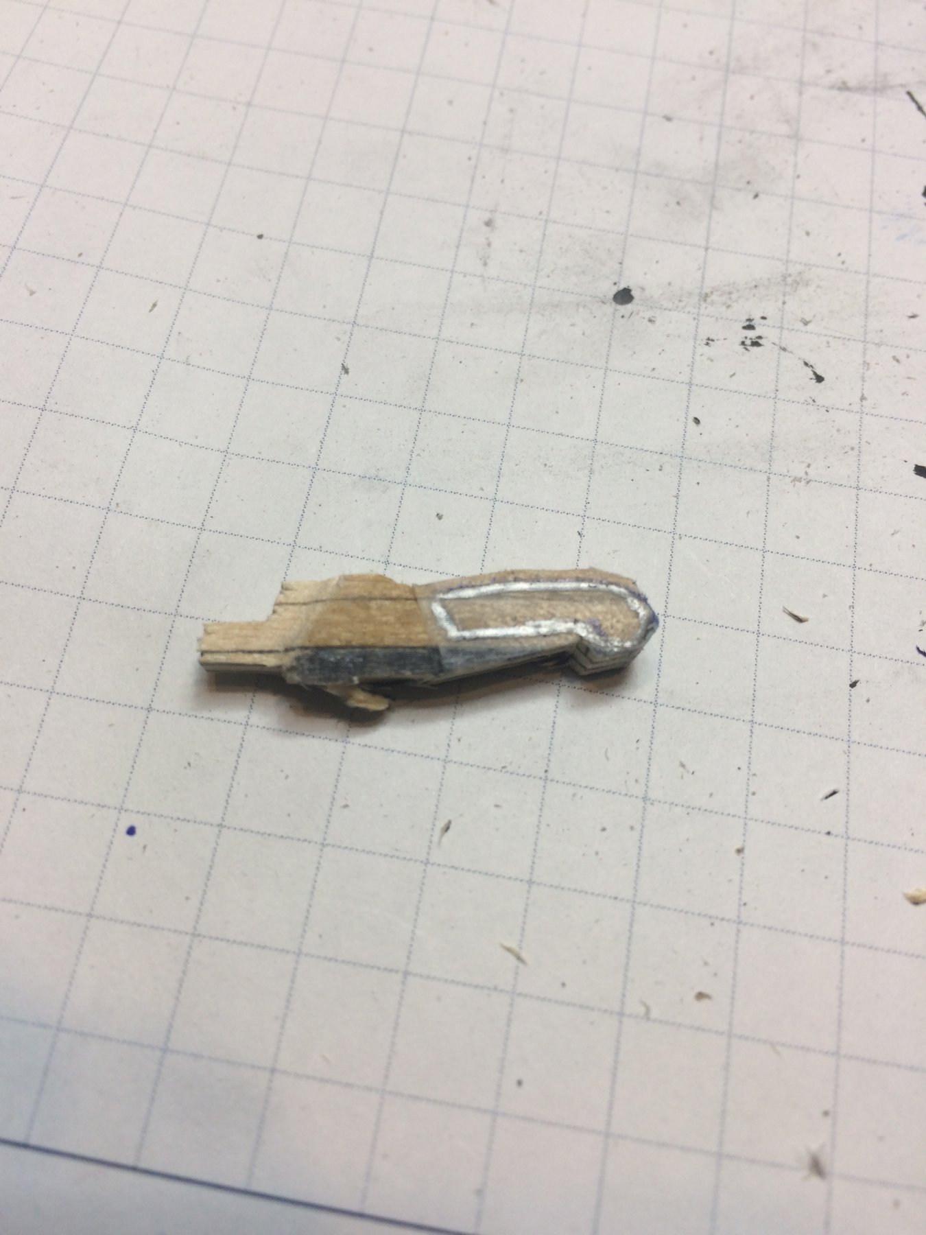
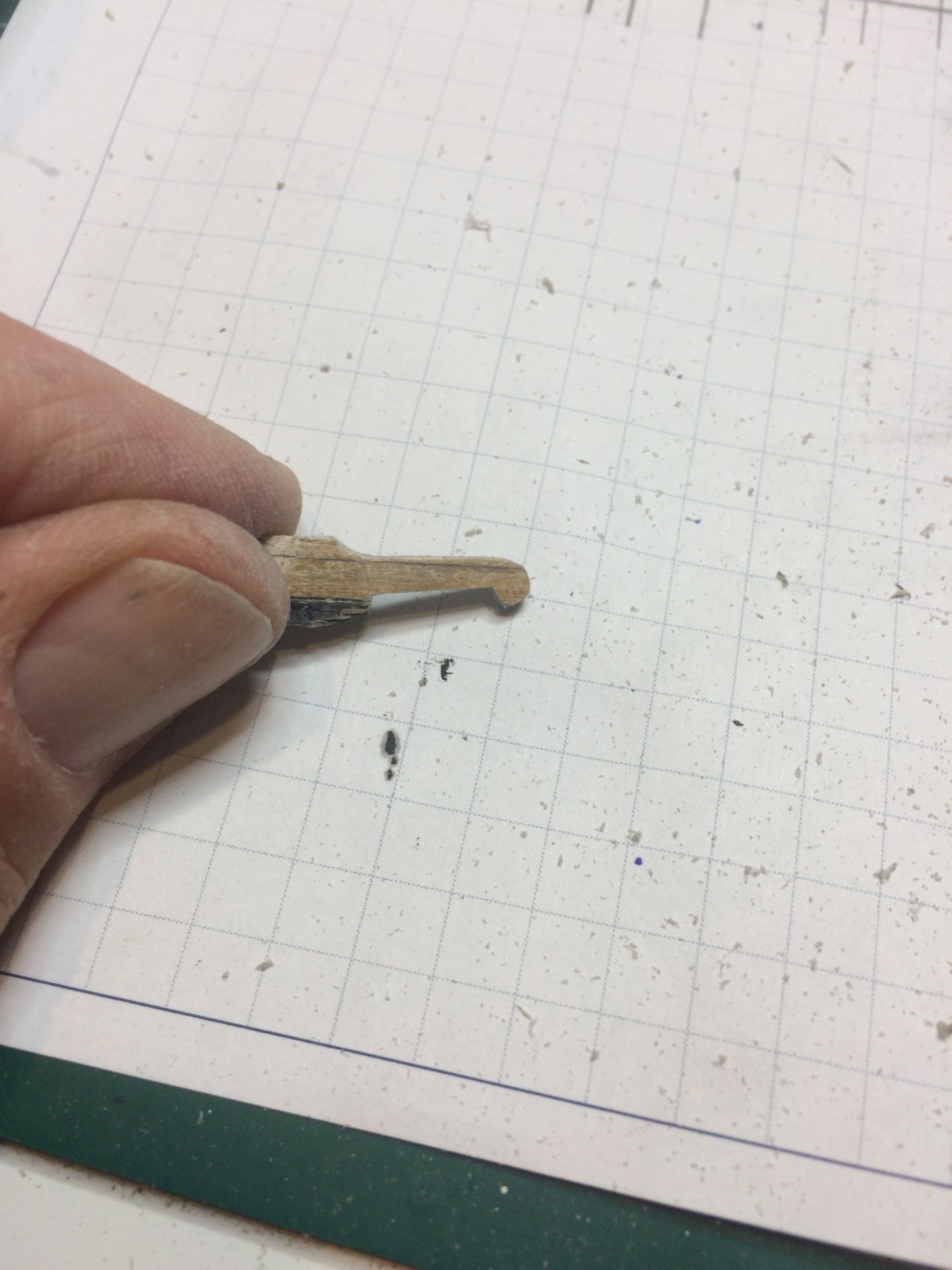
Continued work on head timbers, tiny pieces; i should stop complaining about tiny pieces, should get used to them on Sultana by now...
Anyhow, head timbers were build from .5mm think and 2mm wide scrap piece of boxwood. I even used my new scraper and made them to look like moldings, not sure if it is necessary but someone might noticed that detail if come close enough to the ship...
Again, combination of Chuck' practicum suggestions, along side with other builders' log and little help from a plan, managed to get them all installed. I decided to do painting later, once they are mounted. It appears to be easier task to do painting later than to hold these in hand while painting. On top of that i had to add some more glue to make stronger bond between head timbers and rails...
Here is first head timber in place; the piece was cut a bit over-sized once glue was dried. This leaves me some room for final shaping with sandpaper.

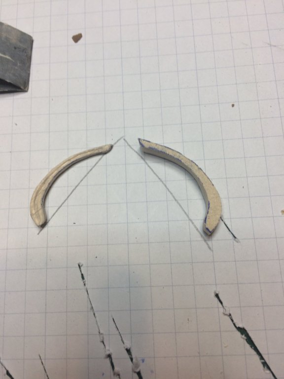
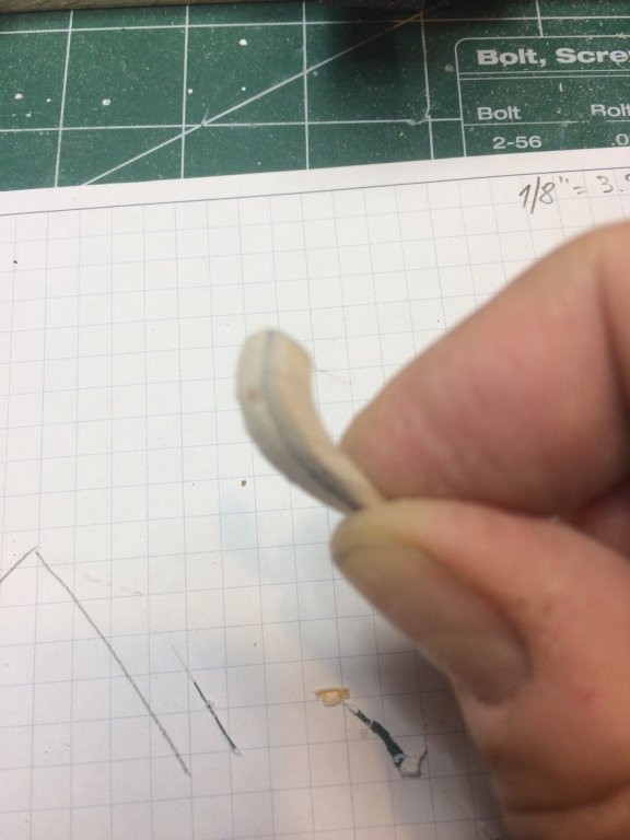
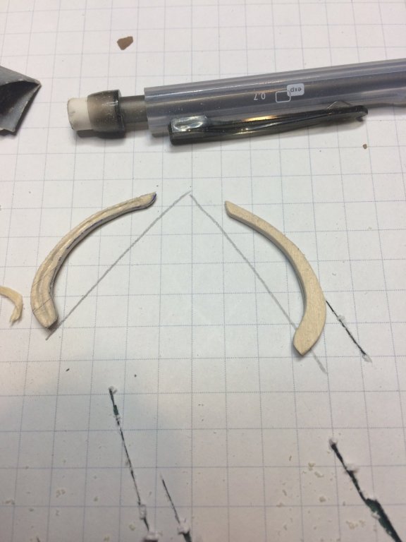
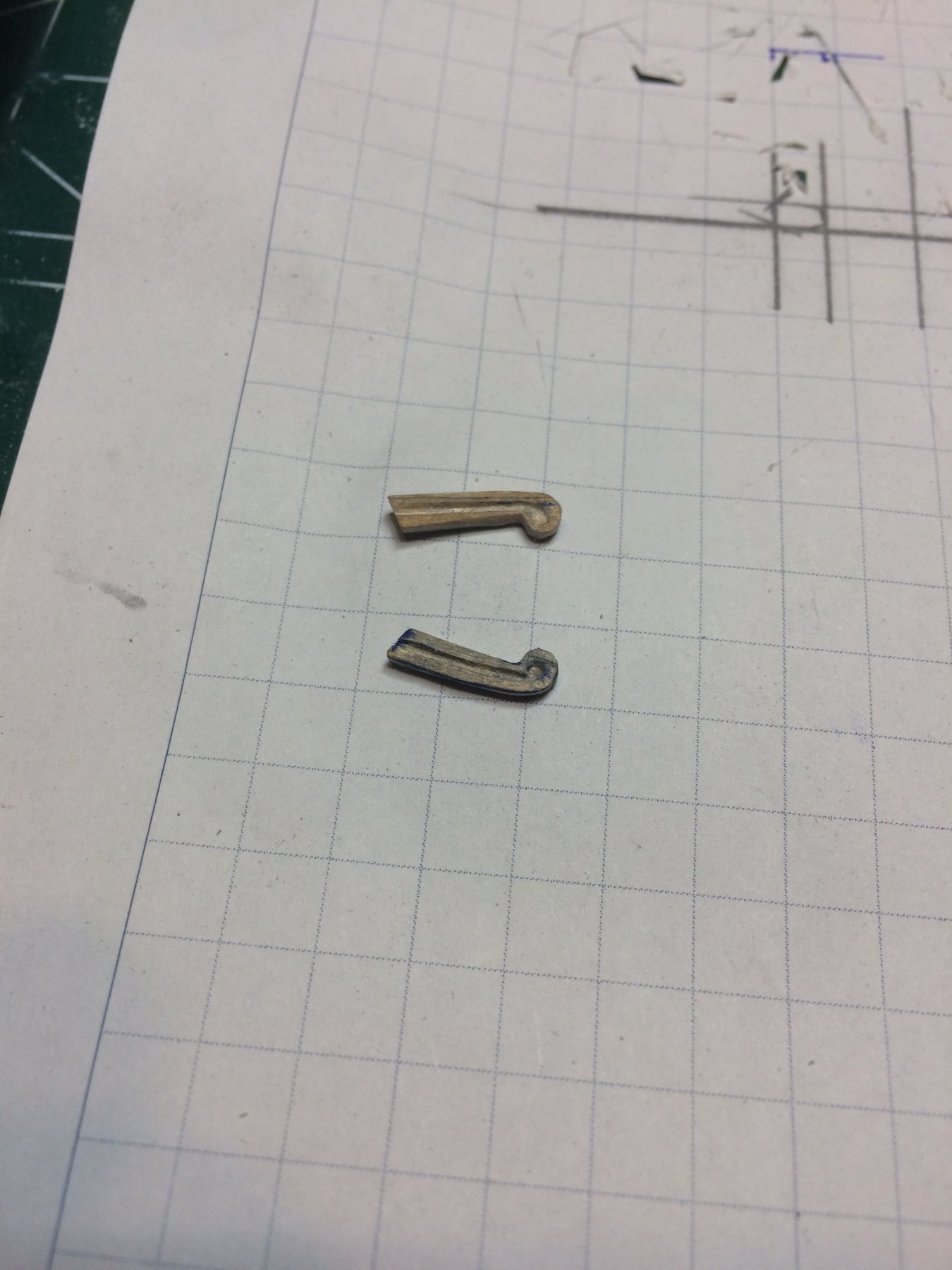
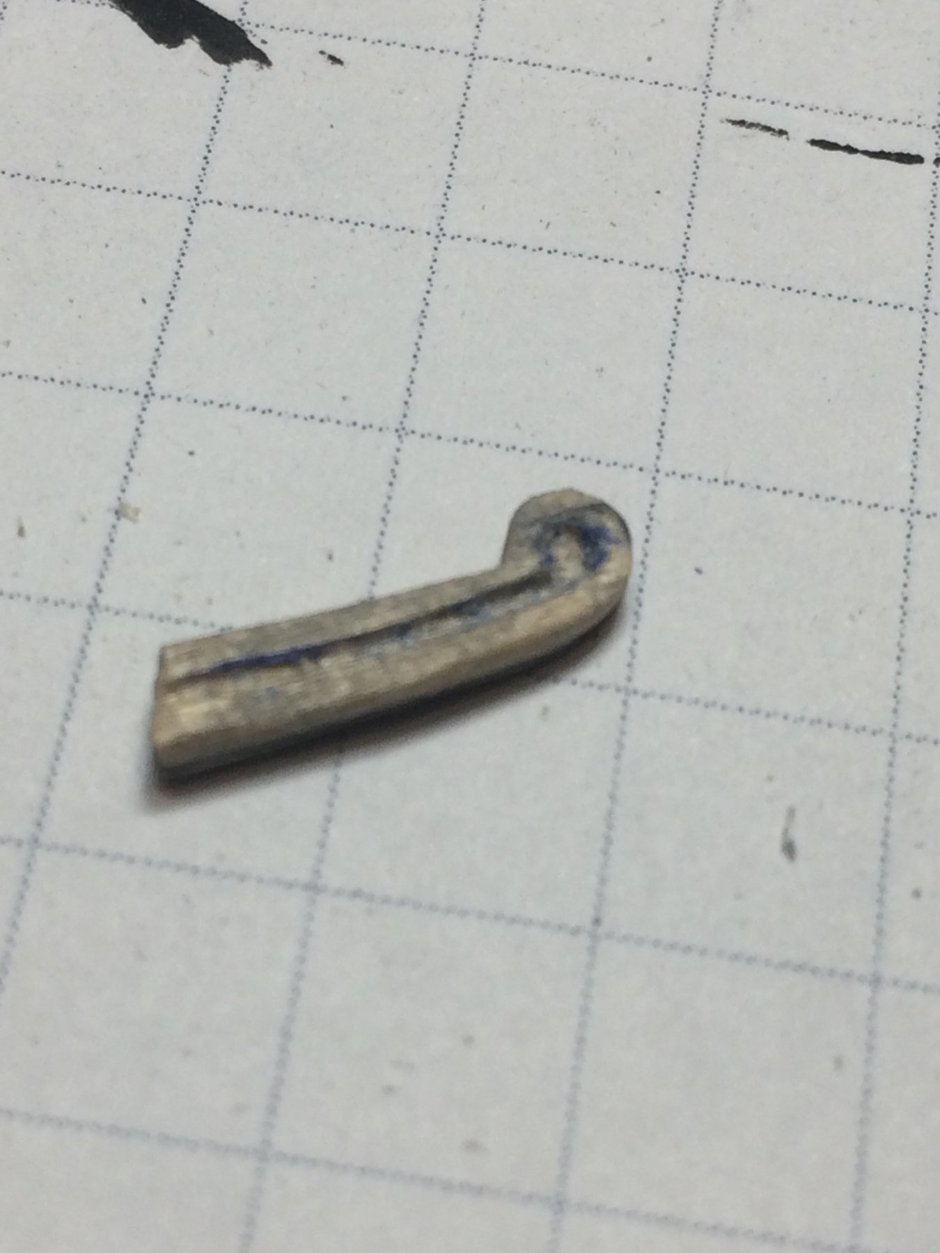
Then i completed cheek knees building process by making last two parts...
The shape was made with scraper,
..short bath in water...
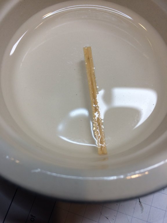
.. and shaping to follow the ship curve...
Mounted and cut to size...

Then i decided to make a head a bit more "complete". Not sure if it is historically correct but it will make the head piece looks better.
The empty space between two head rails will be filled up with wood putty and shaped to fill the gap. I used small piece of toothpick to fill bigger gap and rest of it was completed with wood filler.
So, now model wait for a day so wood filler dries out, than shaping and a nice coat of black paint will be applied. The protective coat of varnish will be done as well on all newly build parts..
Then i decided to work on a ship's boat...
-
-
10 hours ago, GrandpaPhil said:
Well done! The Sultana was my first real wood ship build. You are doing a fantastic job of it!
Thanks GrandpaPhil,
Sultana is my second build but i am contemplating to work on one more, since i have some better understanding what to look for.
I purchased unopened Sultana kit on garage sale for barely any money... but let me finish this one first...
Cheers
-
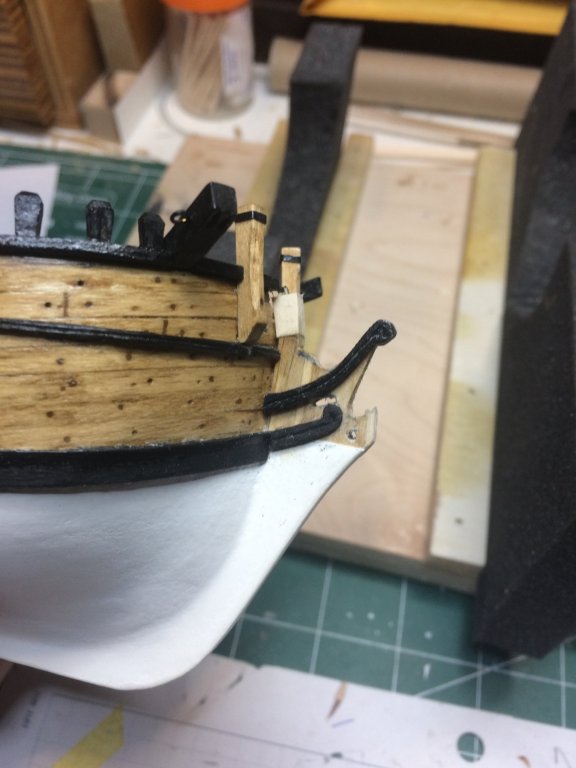
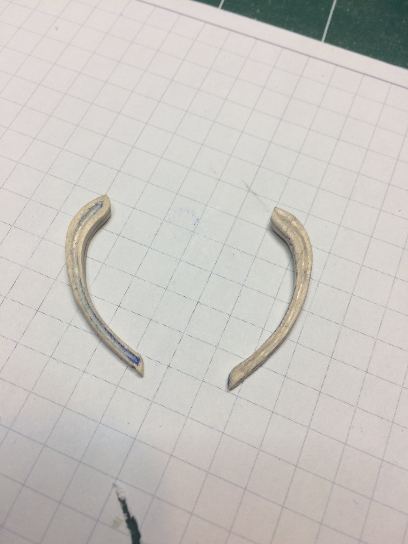
Wrapped up head rail building process today... Worked on second head rail, transfered the shape from first one to the piece of wood, carved, shaped, sanded with sanding paper and files.
The shape was transfered to the scrap piece of boxwood. Cut excess wood with hobby saw and removed wood with carving tools.
And carving....

more carving..
checking shape to the original one...
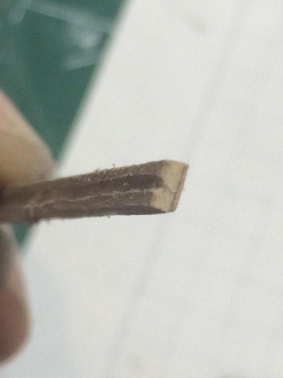
Making the grove with home made scraper...

Once done with carving, painted the layer of flat black and mount on the ship..
Happy modeling..
- lmagna and GrandpaPhil
-
2
-
9 hours ago, Snow said:
All good i say how do you carve out the centre to make canoe look .i just mean what tools Thankyou
No special tools, I cut excess wood with a hobby saw and continue carving with carving knife, #11 knife, sanding paper #80, #400 and #800. The time was the most useful tool since plenty of testing, shaping, retesting has to be done. There is no clear, usable plan drawing for this item...
Cheers
-
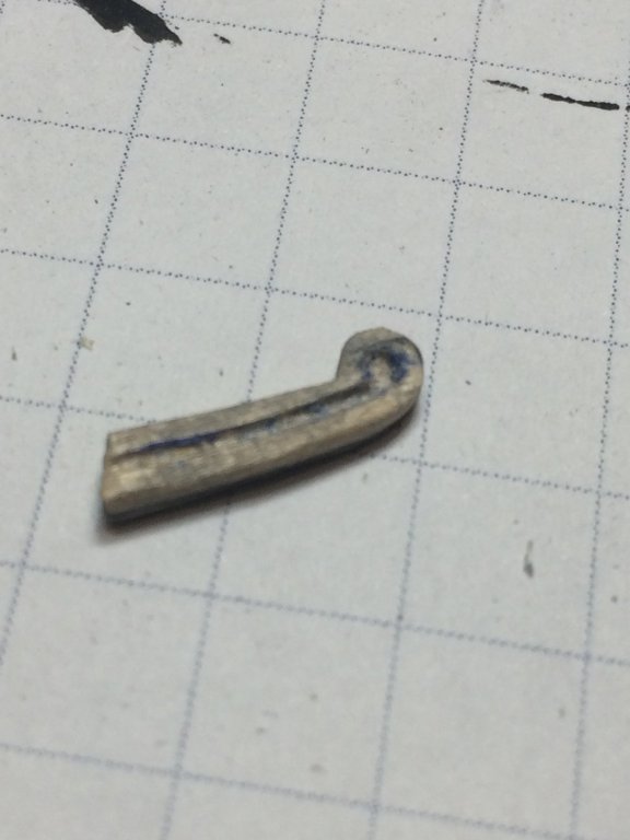
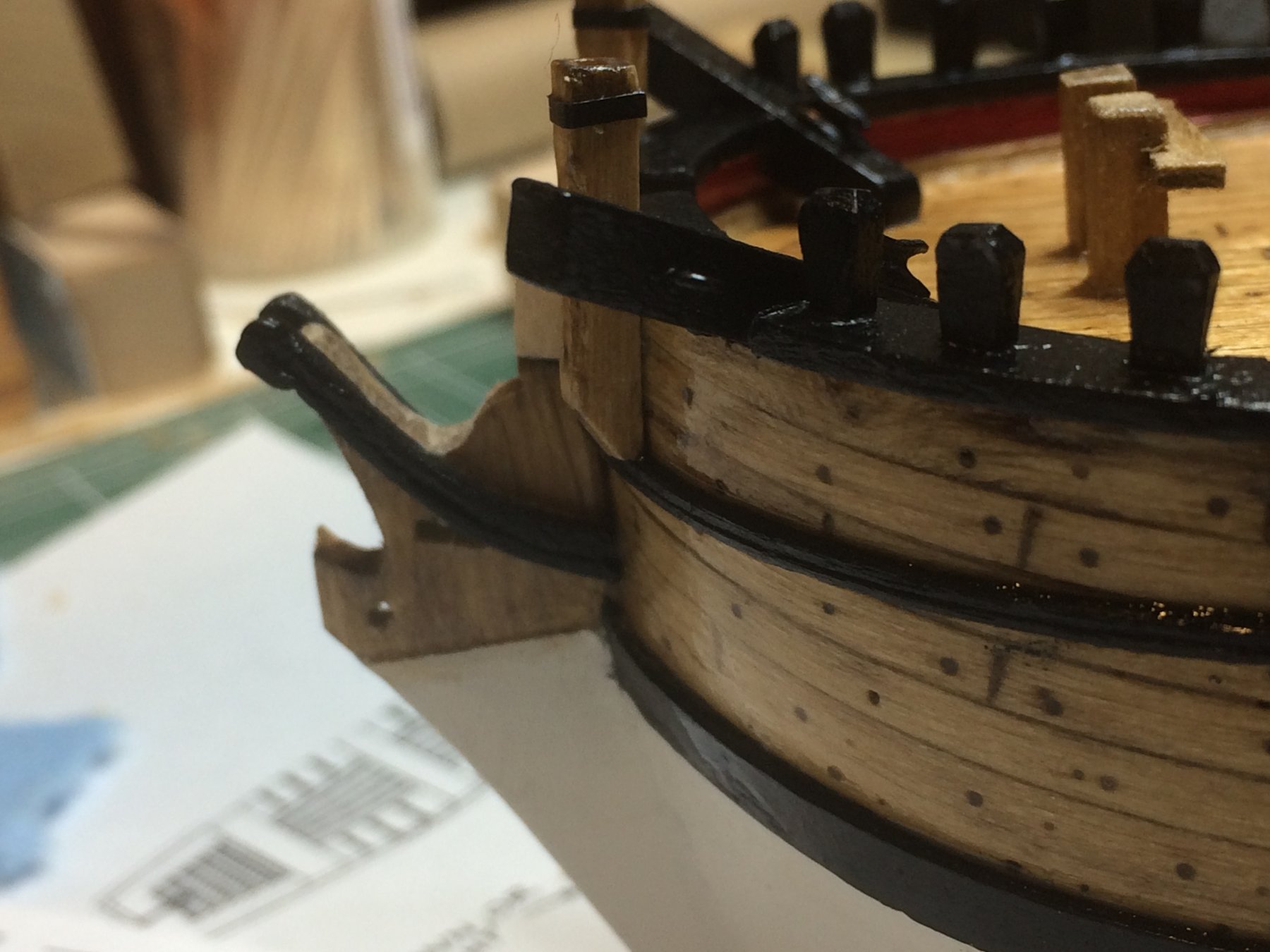
After some time spent in bending setup, the head rails were cut, painted and glued to the ship to meet with cheeks already on the stem.
To provide as smooth as possible transition between two parts i used wood filler to fill out gaps. Sanding part will come up tomorrow.

Using wood filler might not be quite acceptable in ship modeling but i think that end result is more important than material used in building process. These pieces are very tiny and fragile so it would be very difficult to make them in one piece. At least for me.
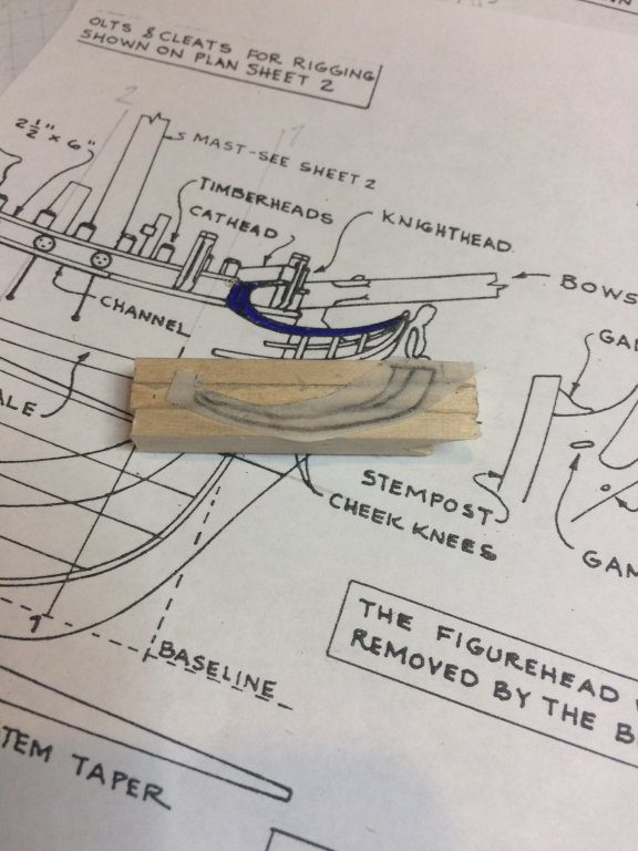
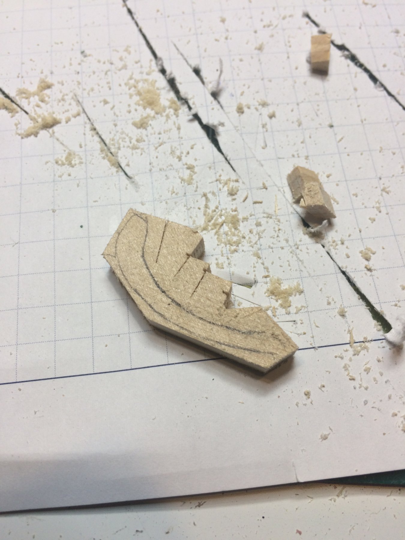
Now, lets see how can we build/carve the head rails. I started with laminating few left over parts, boxwood, into one piece acceptable for carving correct shape. The shape was transfered from plans, cut and glued to the wood. So lets begin carving. I must say i am beginner carver, still have challenges visualizing an end result of carving process so this was a good exercise in proper direction. Repetitio mater studiorum est..
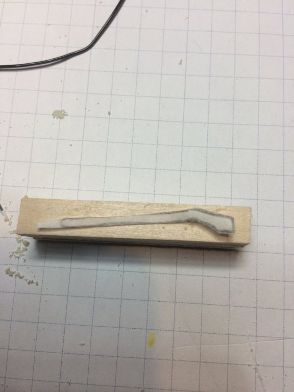
After about two hours or carving, sanding, measuring, testing, carving, sanding, retesting.... i was able to come up with a decent result.
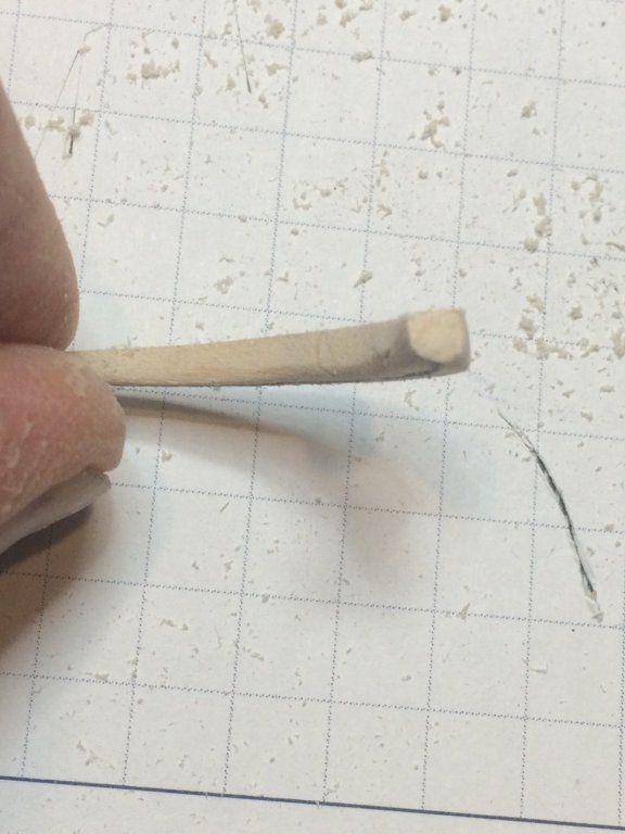
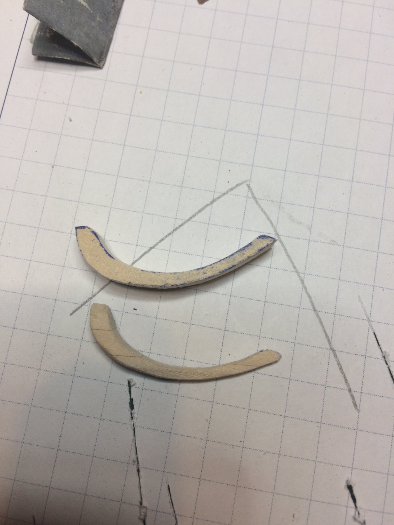
Then using my home build scraper, i made a a groove in head rail, then shaped and cleaned it with a piece of sanding paper folding to the size that can fit in the groove. The rail edges were sanded too with 800 sanding paper.
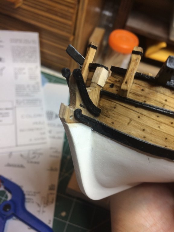
Testing on the ship...
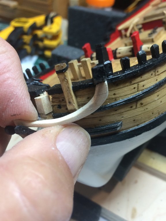
I must admit that the hardest part of this whole process was testing and retesting. The reason for this is that is extremely hard to hold a ship and carving part in correct position, and mark with pencil extra wood that has to be removed. Unfortunately, only two hands available but managed to have it done...
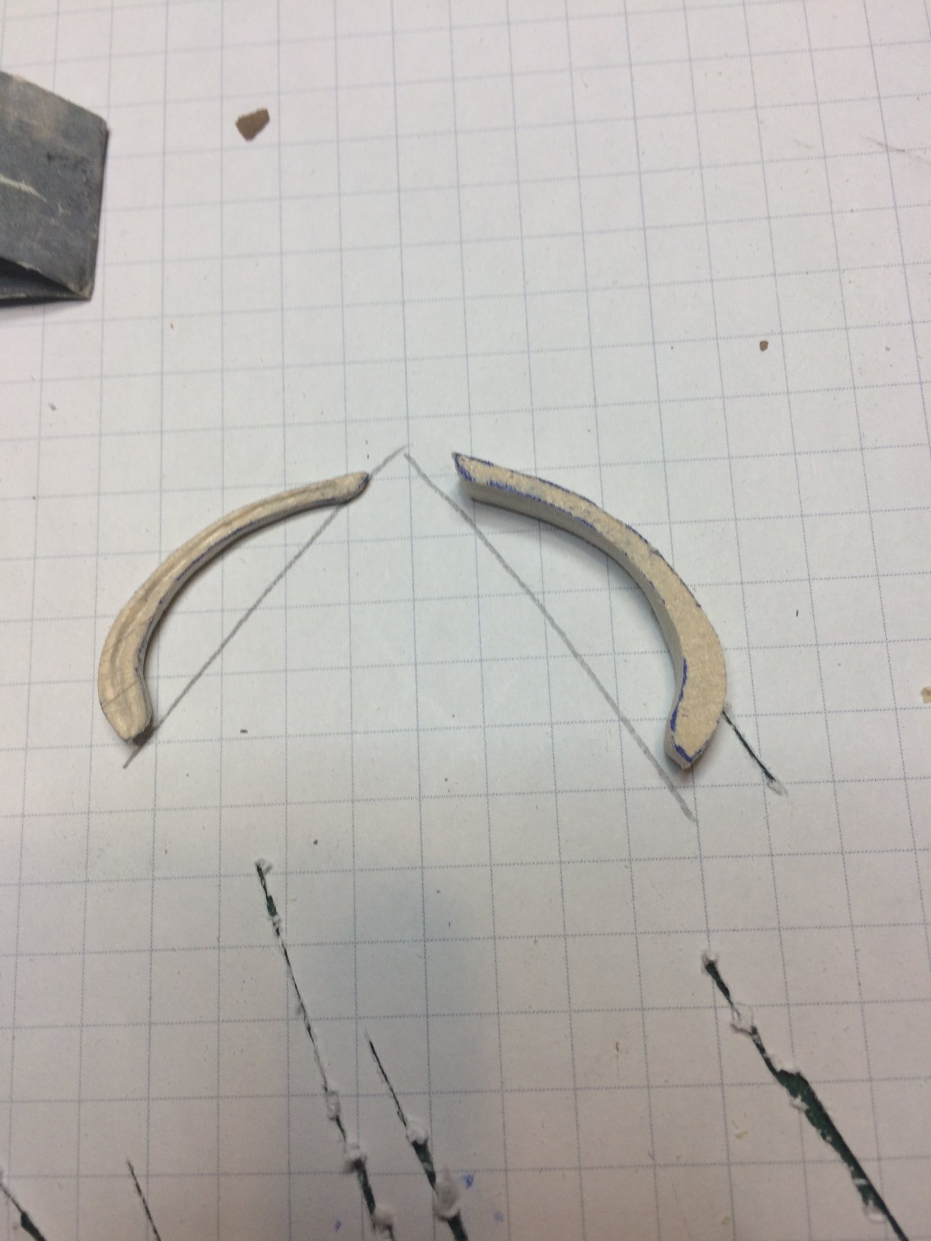
A bit more shaping so the curve is as smooth as possible and final testing on the ship..
I am still not 100 percent happy with a groove, it appears to be a bit choppy but will try to clean it tomorrow. In the meantime i made another laminated boxwood piece that will be used for second head rail...
Happy modeling..
- lmagna, GrandpaPhil and Fernando E
-
3
-
Continue working on cheeks. Started with making a piece of wood that will be used for carving out of few pieces of leftover planking boards, glued together like in few previous posts. Transfered shape and start sanding and carving..


After light layer of black paint i glued them to the ship head.
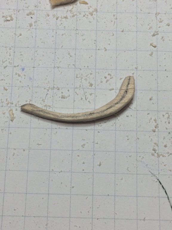
Then part of the cheek that extend to the ship was carved next...
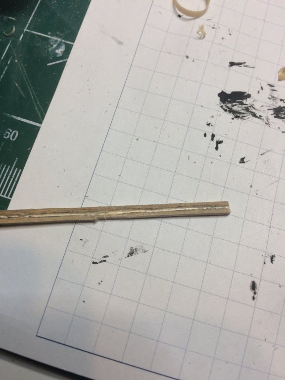
This part do require a bit of a curve so quick bath in the water for a few minutes and curved for tomorrow assembly..
Happy modeling..
- lmagna and GrandpaPhil
-
2
-
21 minutes ago, lmagna said:
I think I understand reason for the timberhead method of build now. I kind of feel stupid, (Not for the first time today either). Thanks for the pictures.
If more detailed pictures would be beneficial i can snap few extras...
-
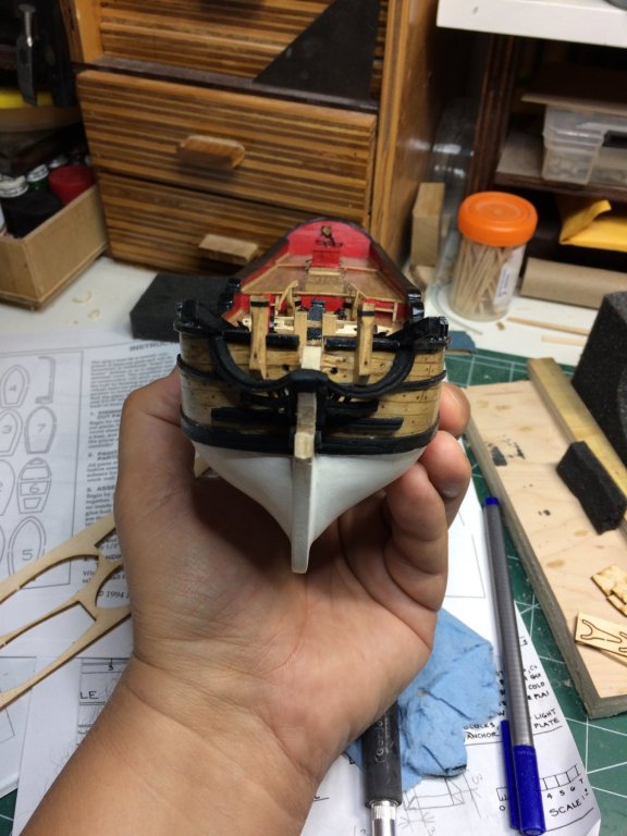
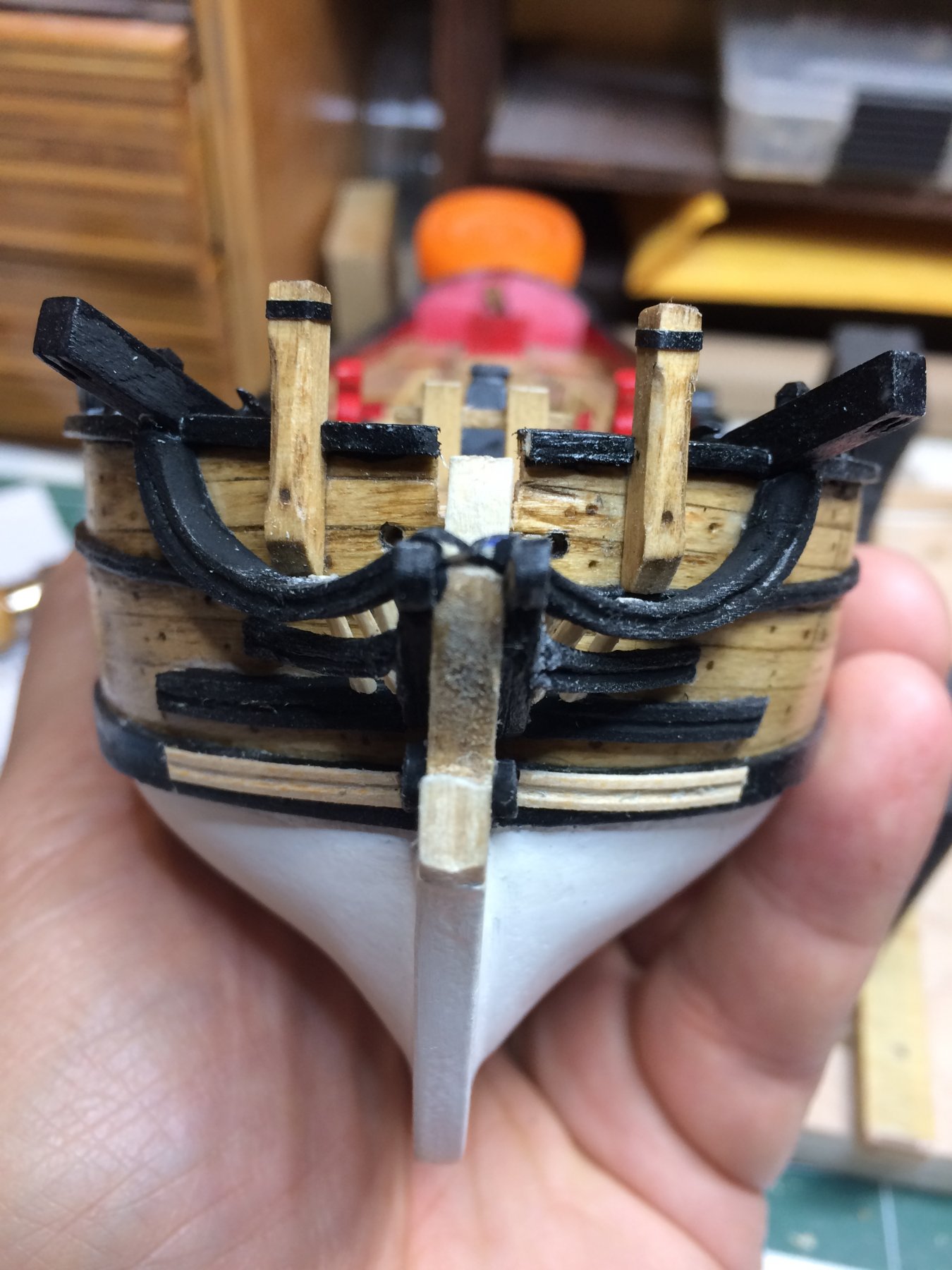
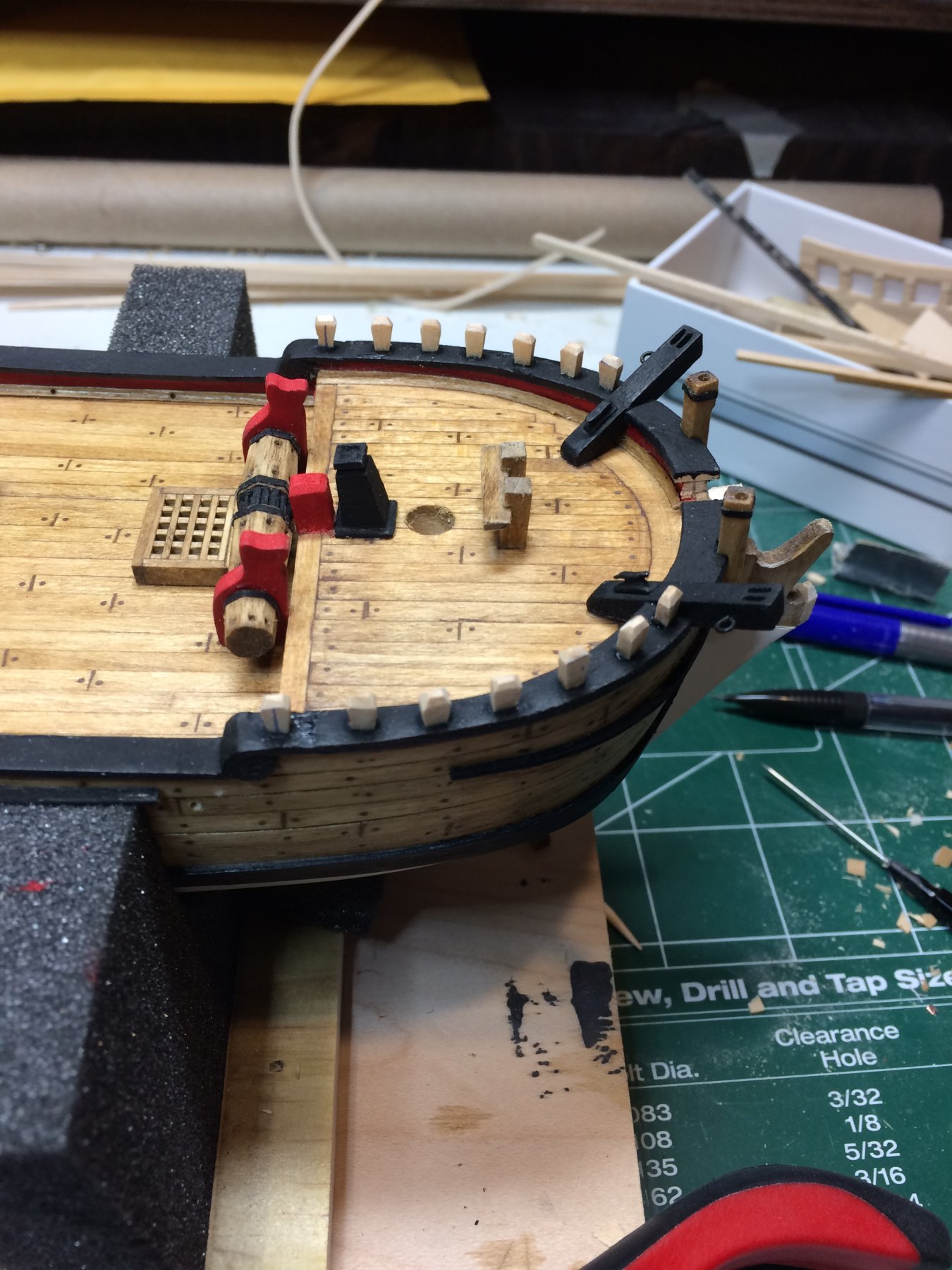
Timberheads are completed and painted in black.
Finished carving of second cheek. Both of them were painted in black and glued to the ship head. Must say that carving is time consuming process especially on these small items.
Then i applied a protective layer of varnish on whole deck and all deck furniture.

That was all for today, not many pictures but time well spent..
Happy modeling..
- lmagna, GrandpaPhil and yvesvidal
-
3
-
Timberheads completed, just a layer of black paint is left. Usage of pins appears to be really good move. Most likely without pin, timberheads will be very fragile parts. I have left few spares (with inserted pin) just in case something gets horrible wrong..

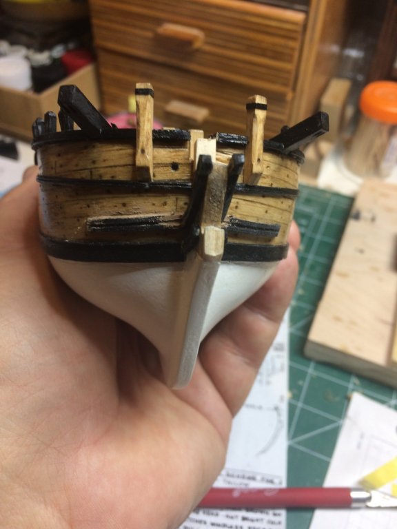
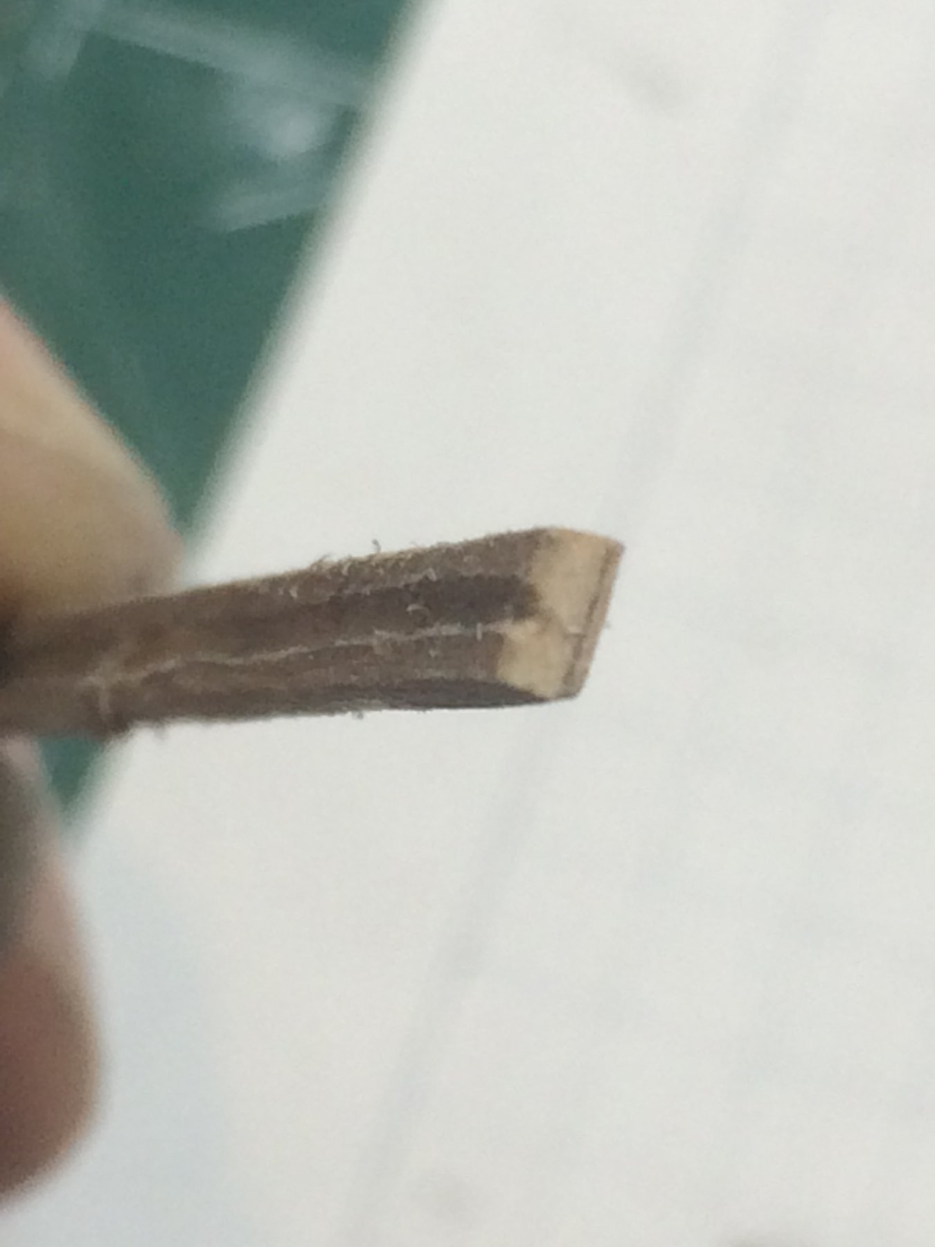
I have made plenty of plan copies so i can cut it and trace to the timber if needed. I had to make two holes in stem (not quite sure what technical term will be for these two holes), cut and traced the shape ..
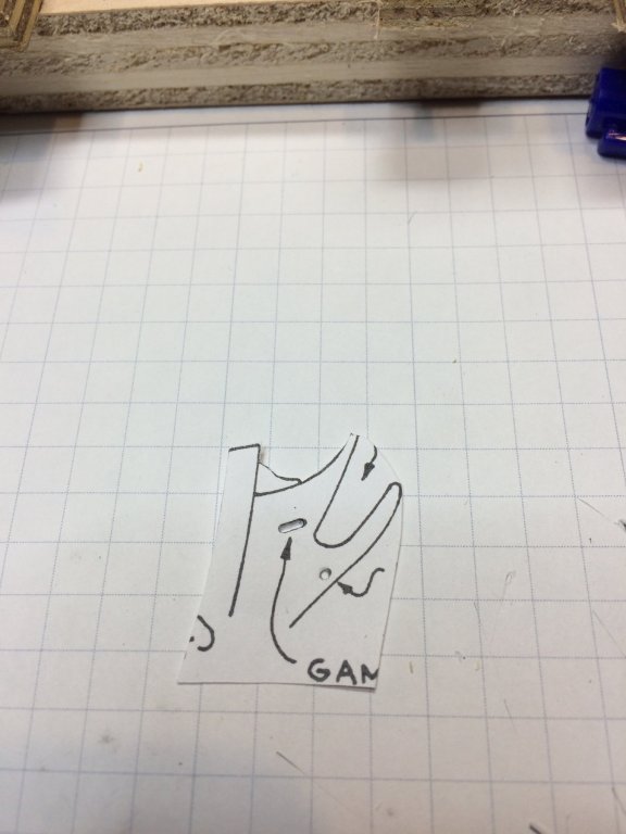
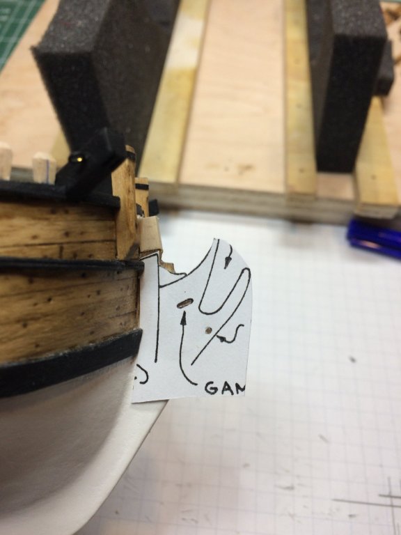
.. with a needle point tool made marks on the stem and then drilled holes with 0.44mm. First with 1mm drill bit and then with 1.3mm the holes were widened. A bit of file sanding and work completed.
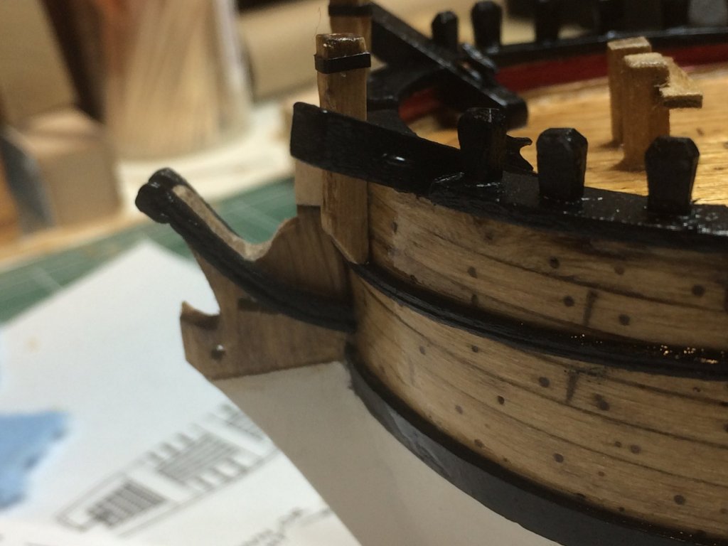
On this picture it is better visible that length of the stem is not quite appropriate and extra patch will be needed (or planing ahead and have longer stem at the beginning).
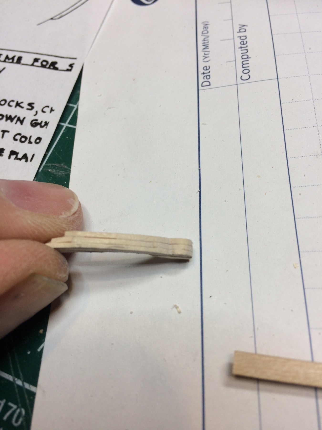
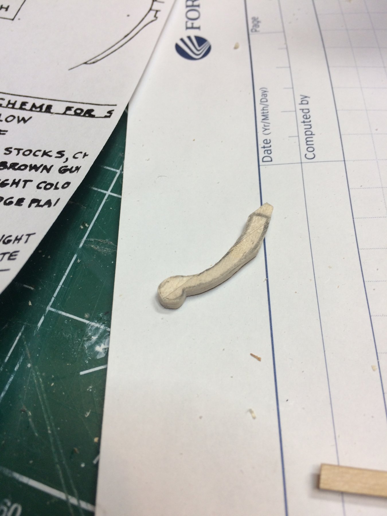
Cheek knees.. another small and tiny parts to deal with.. now, i red Chuck' practicum ahead of time. During the making process i broke three knees. Most likely the wood is either tiny or i was not following wood grain but i ended up using "laminated approach". I glued three planks (1x3mm in size) lengthwise (like this ---), then glued two planks on the top of it ( --) and two another planks on the bottom ( --) getting it all in layers.
This should be strong enough to take abuse by #11 knife and other shaping tools.. Since knees will be painted in black visible layers will not be an issue..

Started to carve...

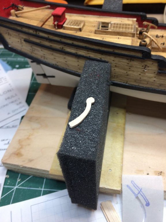
Completed for today; tomorrow a bit more carving...
Happy modeling.
- GrandpaPhil and lmagna
-
2
-
40 minutes ago, lmagna said:
Thanks for the explanation. Still not sure why two piece is better than just making them in one piece but I will wait for the pictures. I am sure that they will look good no matter what.
It would be much better to get them in one piece but i did not pay attention to that. Following kit plan to the letter get me to this stage and not reading Chuck' practicum ahead of building time, just added a bit of spice to it.
If i would do the stem again, i will make sure i have extra length. This goes into my building notes for future references.
-
13 hours ago, lmagna said:
I suspect that timberheads would be more, "Save the tree" types anyway.
I do have a question though as my needing to build timberheads is still ahead of me at some point. Why did you make the pieces in two parts instead of one full piece of head and post?
That could be used as well... Depends on audience...
If i understand your question right, the reason for two pieces in stem area is that the stem is actually shorter than needed. It is visible when you test position of bowsprit after opening for it is cut. I did not read Chuck's practicum that diligently so made the same mistake he did... Now a added small "patch" and after all other parts are in place it should be hardly visible (hopefully).
Thanks for following..


.JPG.7783be6231e73ba7efb180bbb636d4e3.JPG)


Sultana 1767 by moreplovac - FINISHED - Model Shipways - 1/64 - Colonial Schooner
in - Kit build logs for subjects built from 1751 - 1800
Posted
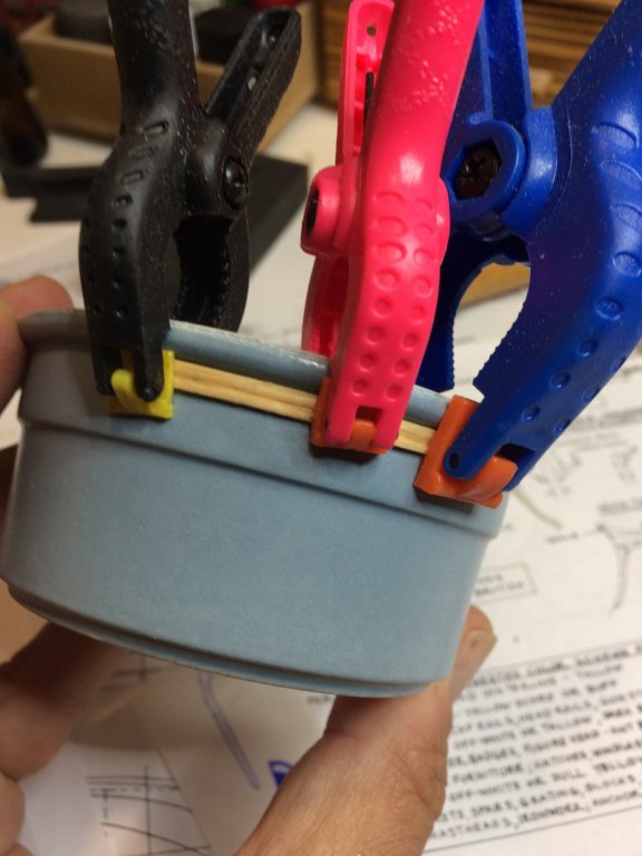
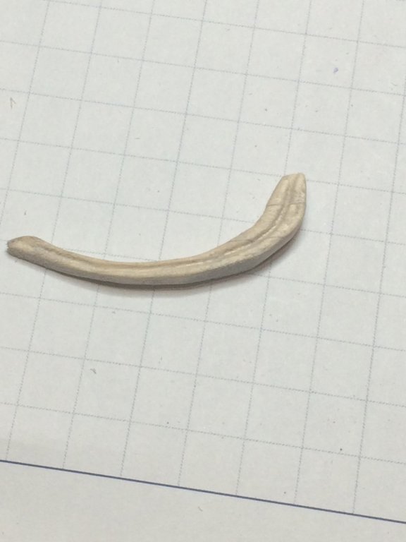
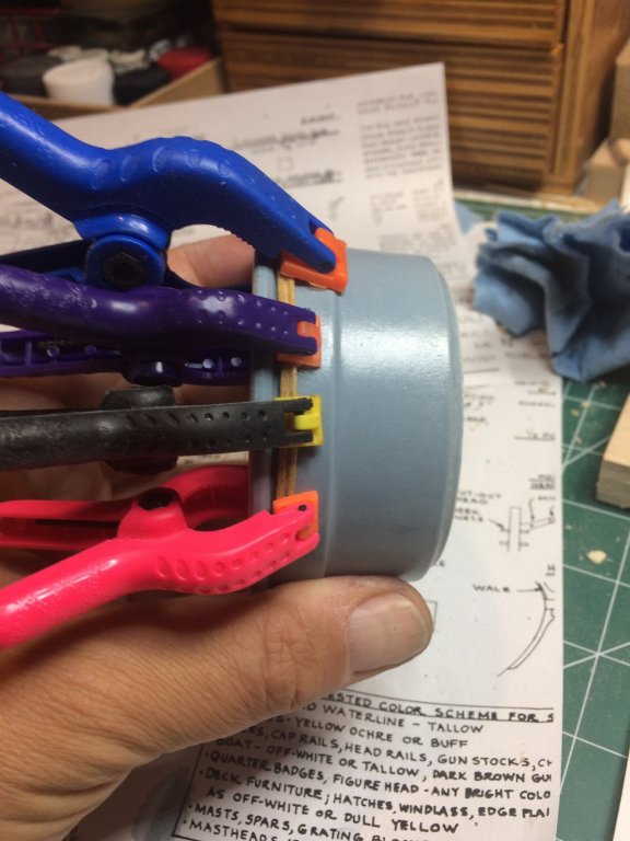
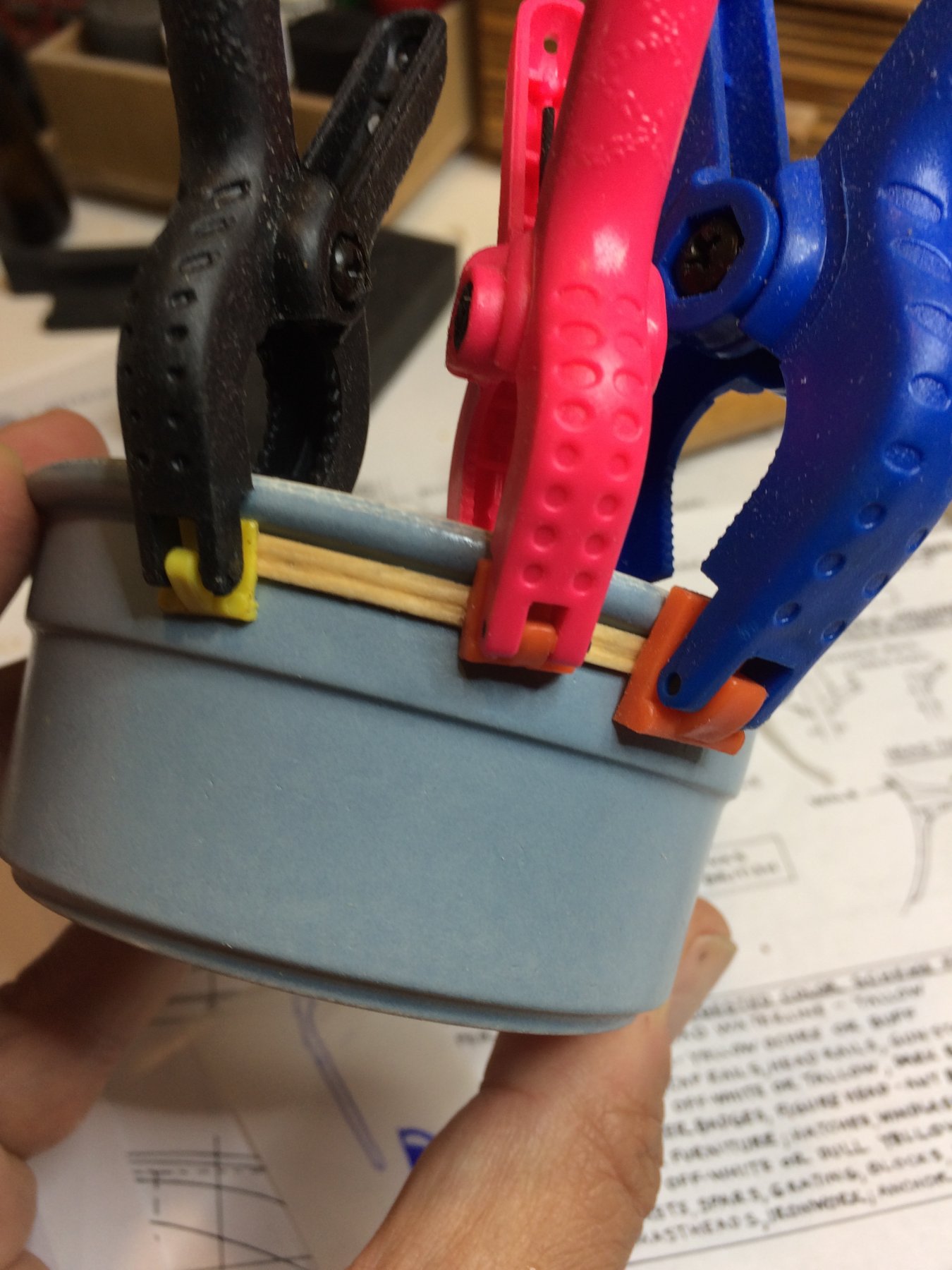
A bit of work was done on ship boat; yesterday i painted a molding in black that will be mounted on the boat. The molding was already shaped (few minutes in water and twisted around boat, secured with a rubber band).
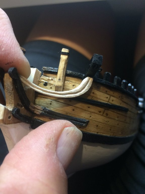
The molding was then glued to the boat. There are few touch ups required but not a big deal.
Inside of the boat was covered with golden oak stain, the same as rest of the ship.
Few other items, rudder, tow rope, a pair of oars will be added to complete the boat... To come...
Happy modeling..