

KJackson
-
Posts
66 -
Joined
-
Last visited
Content Type
Profiles
Forums
Gallery
Events
Posts posted by KJackson
-
-
LINING OFF THE HULL
Last week between work rearing its ugly head and a getaway trip with friends, I didn't get to my model. What I did do was reading and research in preparation for the hull planking.
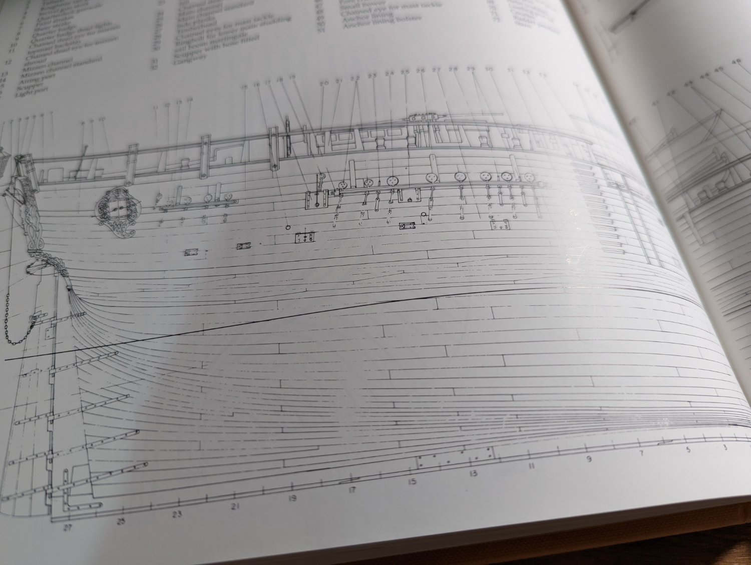
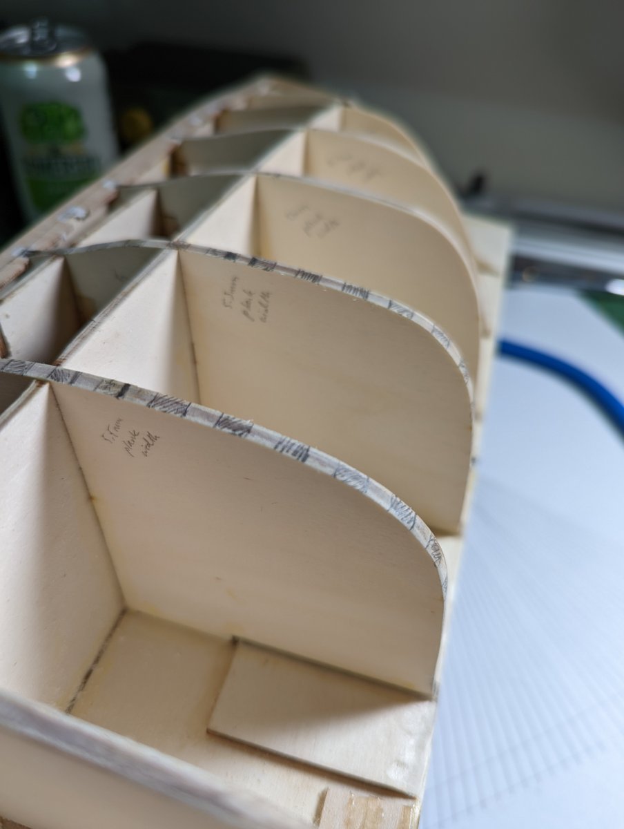
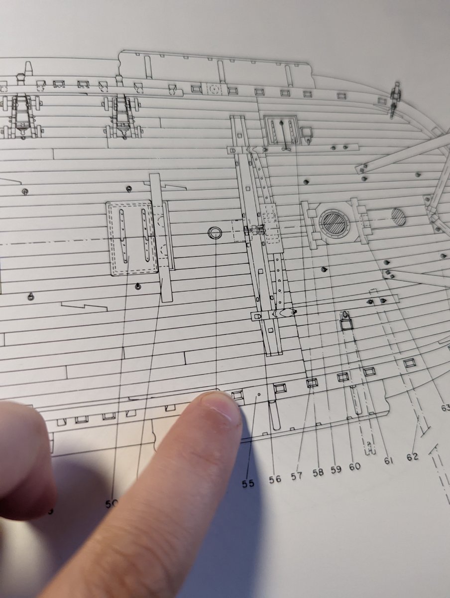
I used Marquardt's drawing of the external hull to count the total number of planks needed for the ship - 38 for those from the quarter deck and 35 for those from the upper and forecastle deck.

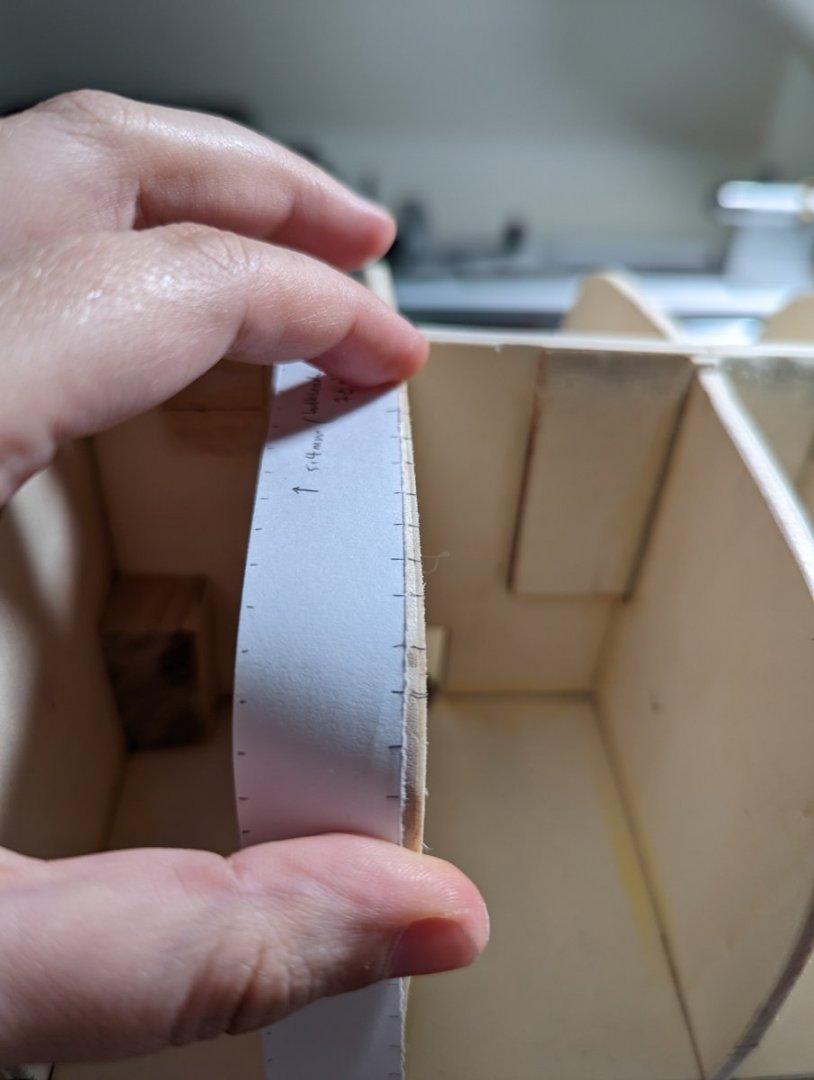
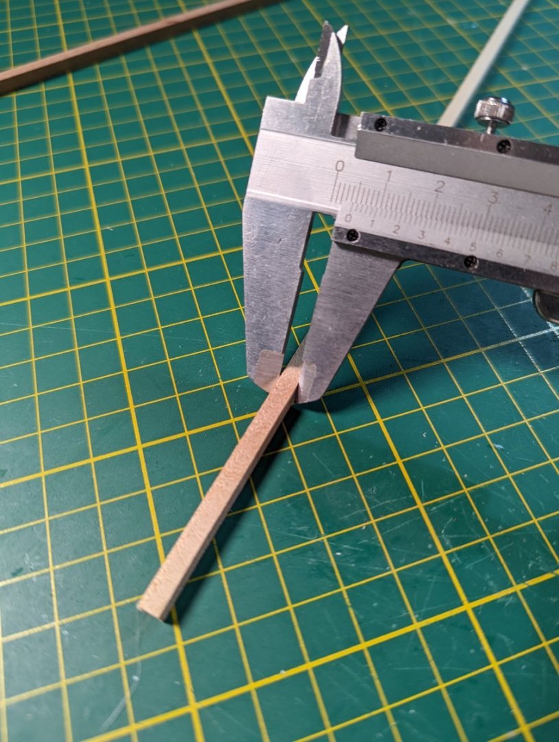
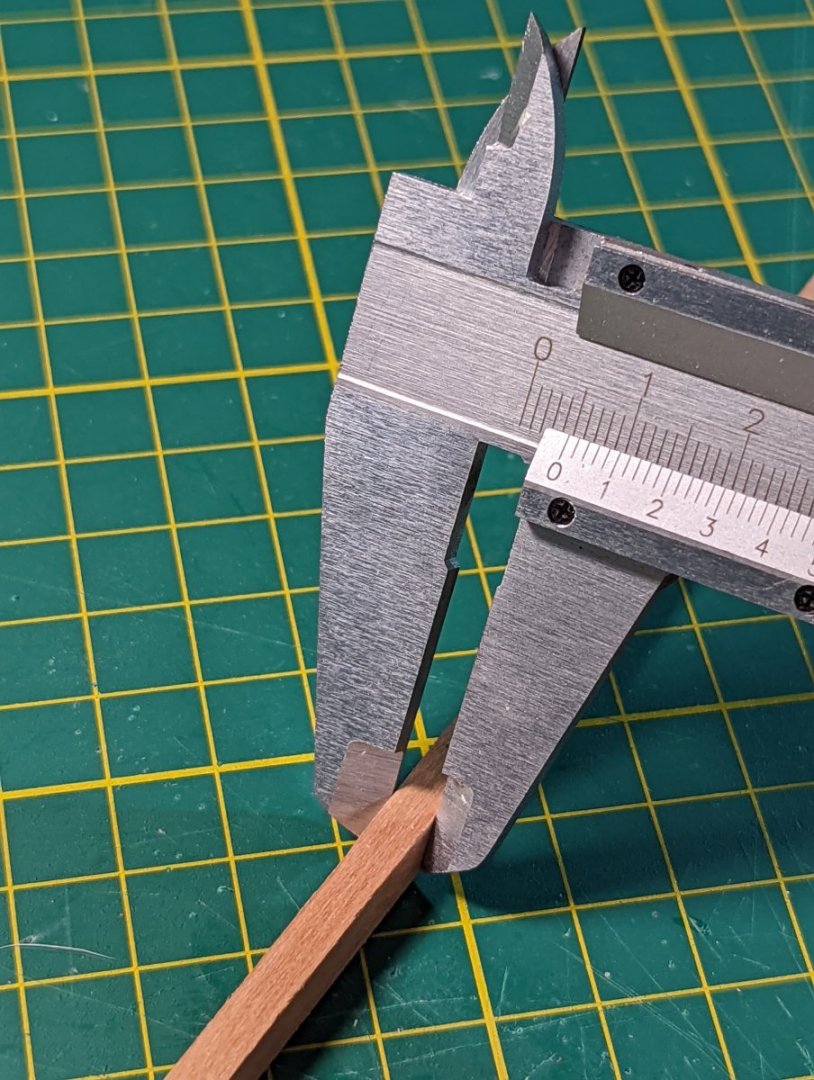
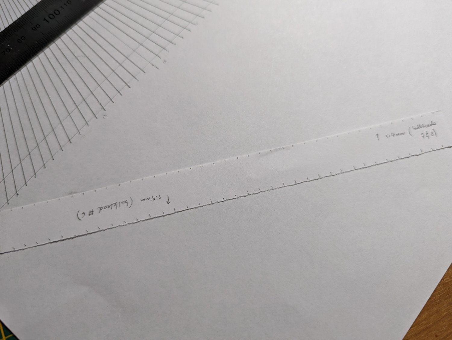
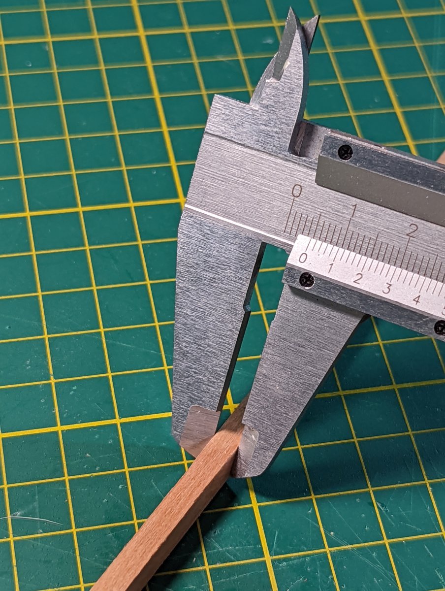
I then measured the distance from top of bulwark to keel on each bulkhead to figure out the required taper. This ranged from 5.5mm at its widest to 4.6mm at its narrowest (before the bow).
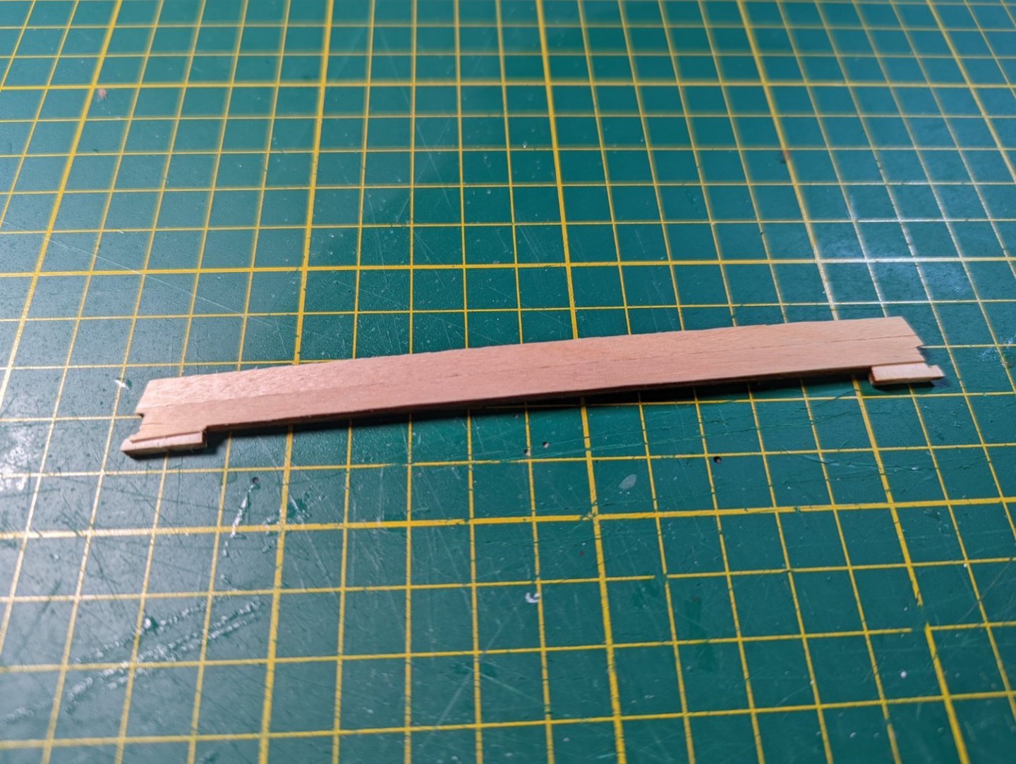
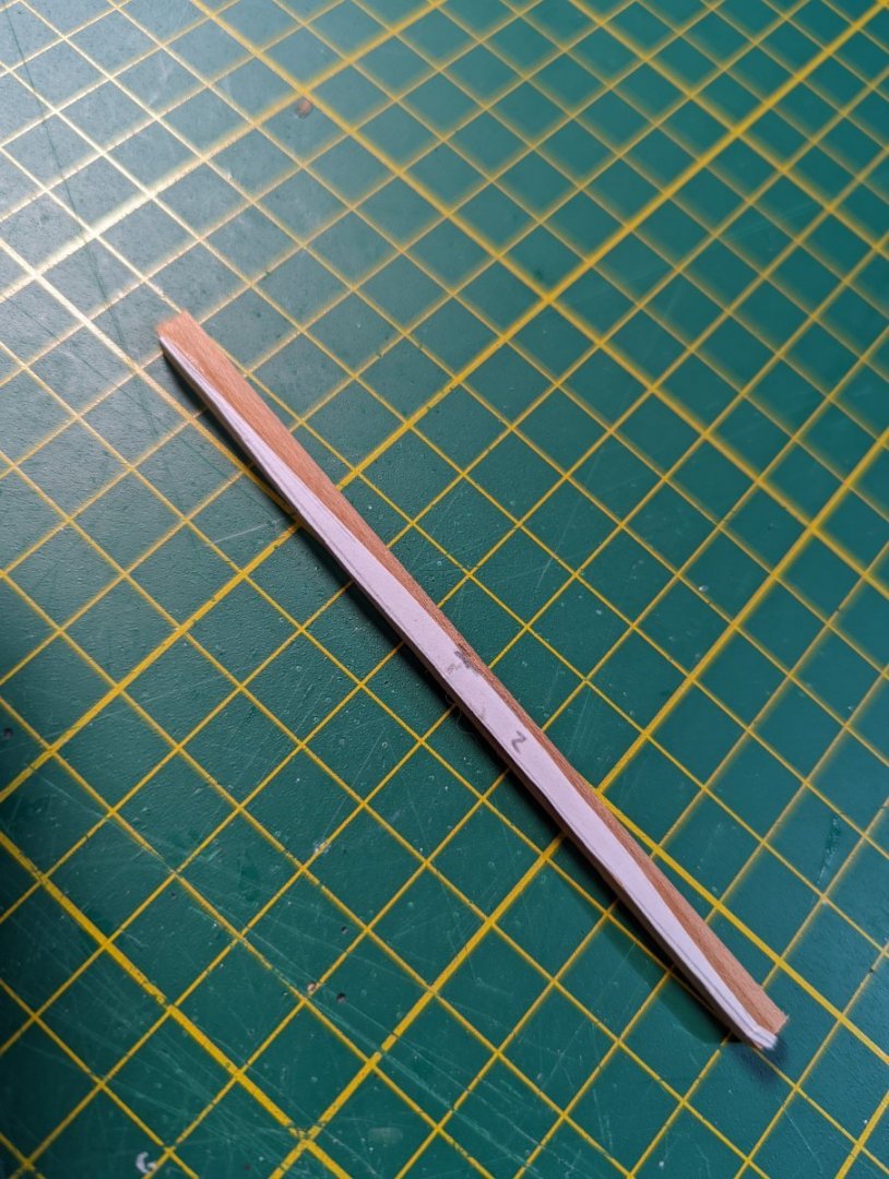
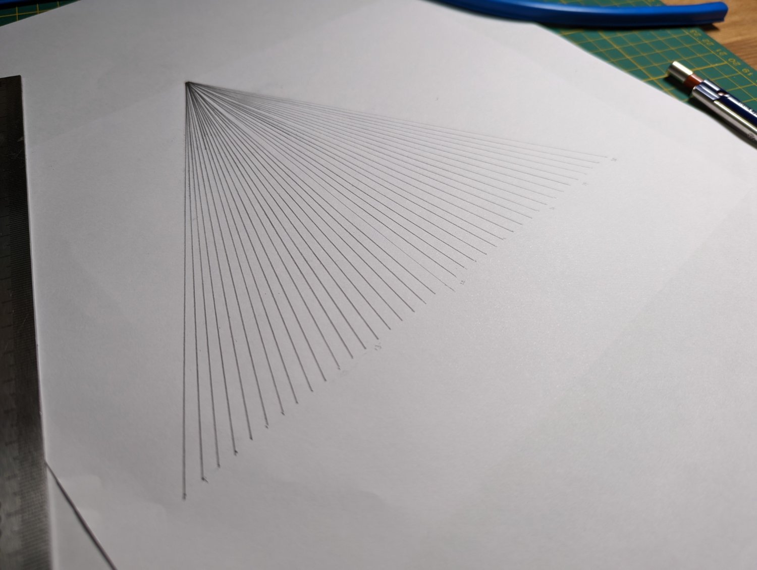
I followed Chuck's planking instructions and drew up a planking fan and transferred each measure onto the bulkhead in question using a marked strip. This helps me plan what the planking will look like.
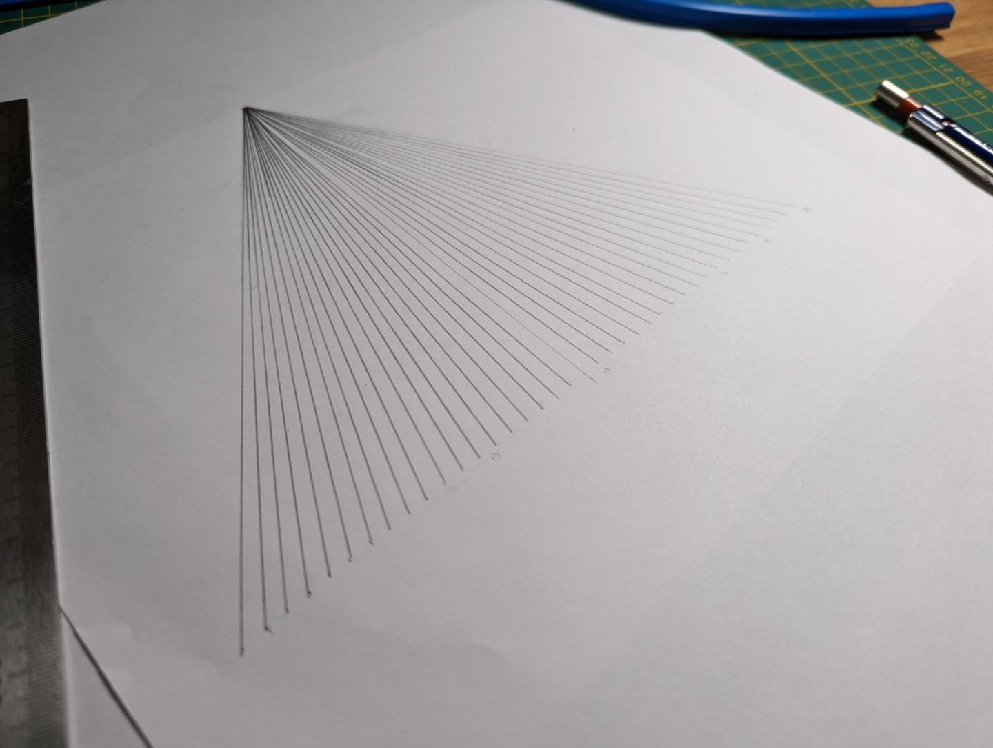

Please note that this is the first time I've tried this approach; my previous ship was all "plank and taper as I go and hope it all works out". So keep this in mind as reading!
I get the second layer of planking so this one has a good bit of leniency in case things go skewiff. However, it's fun to try more advanced techniques.

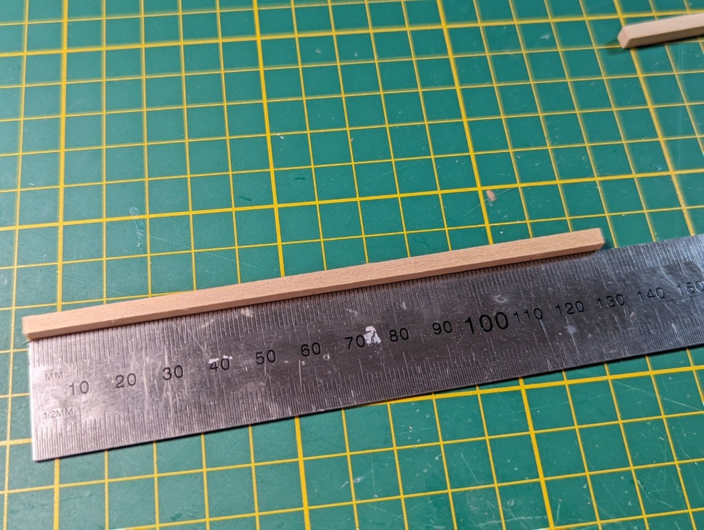
I toyed with cutting the planks to 120mm lengths on the first layer. After playing around, however, I decided to just do full strips as this will help with the overall smoothness of this layer before the final planking.
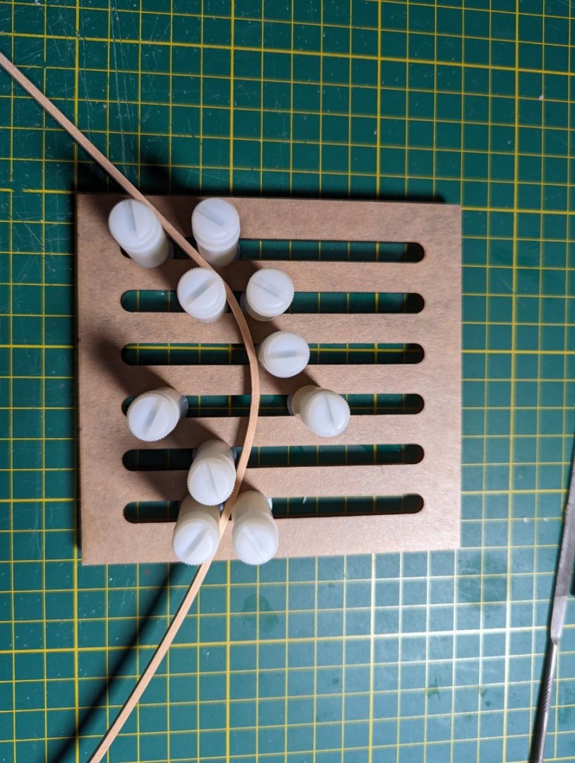
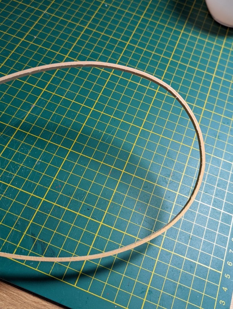
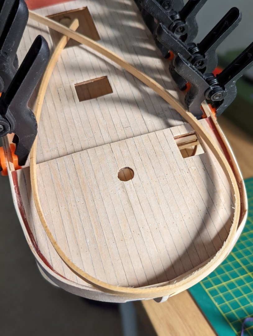
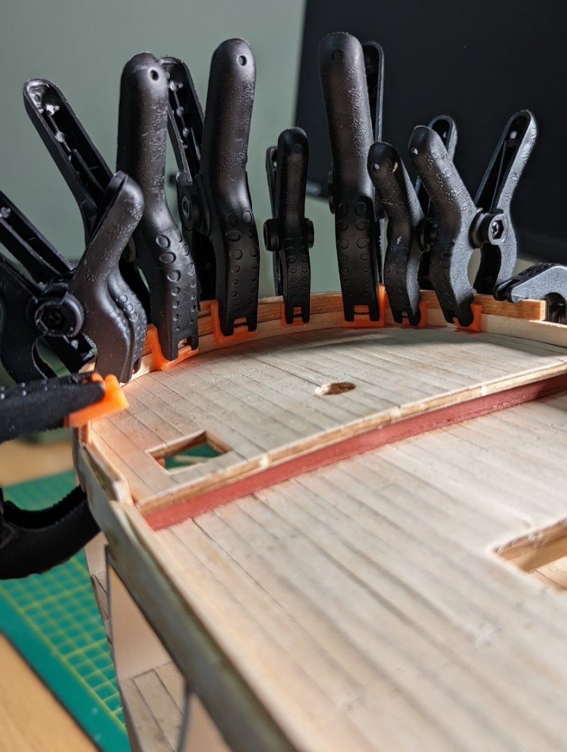
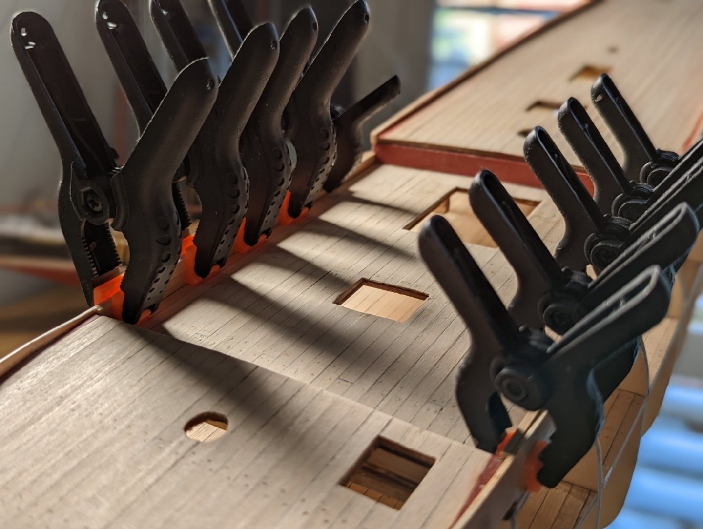
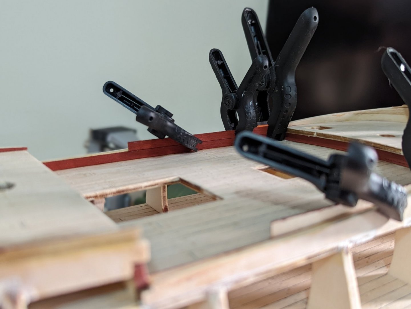
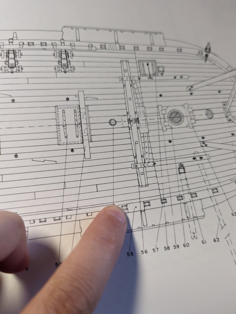
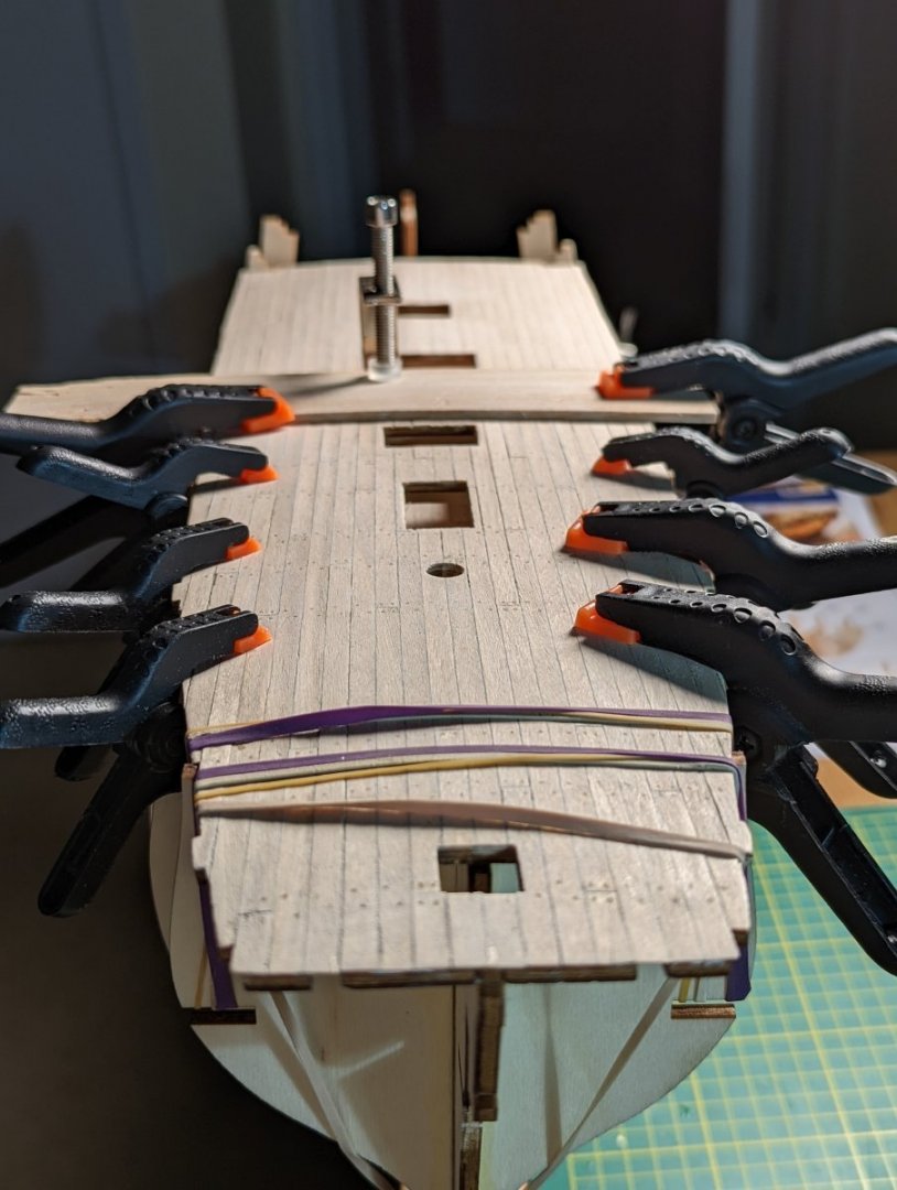
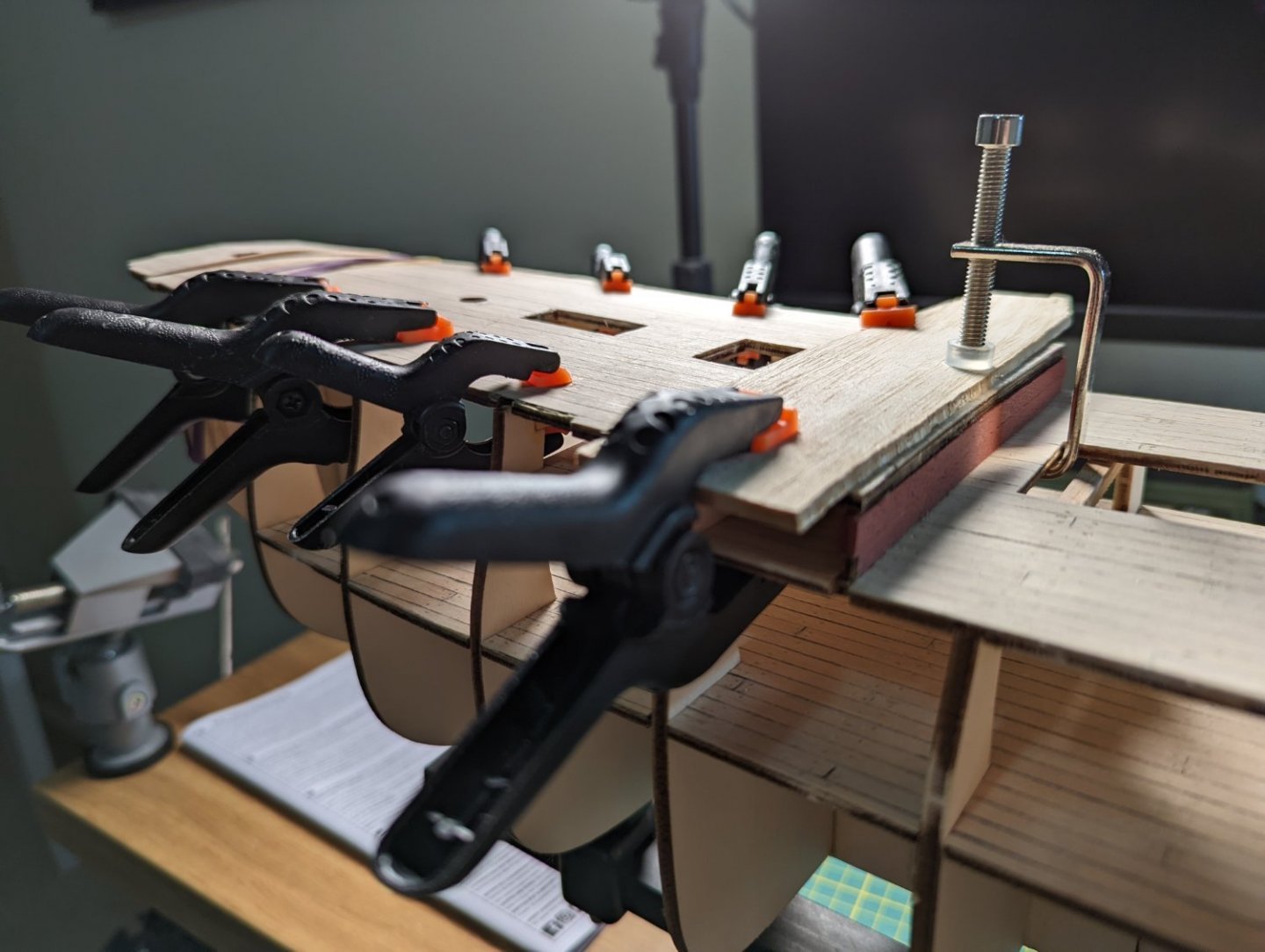
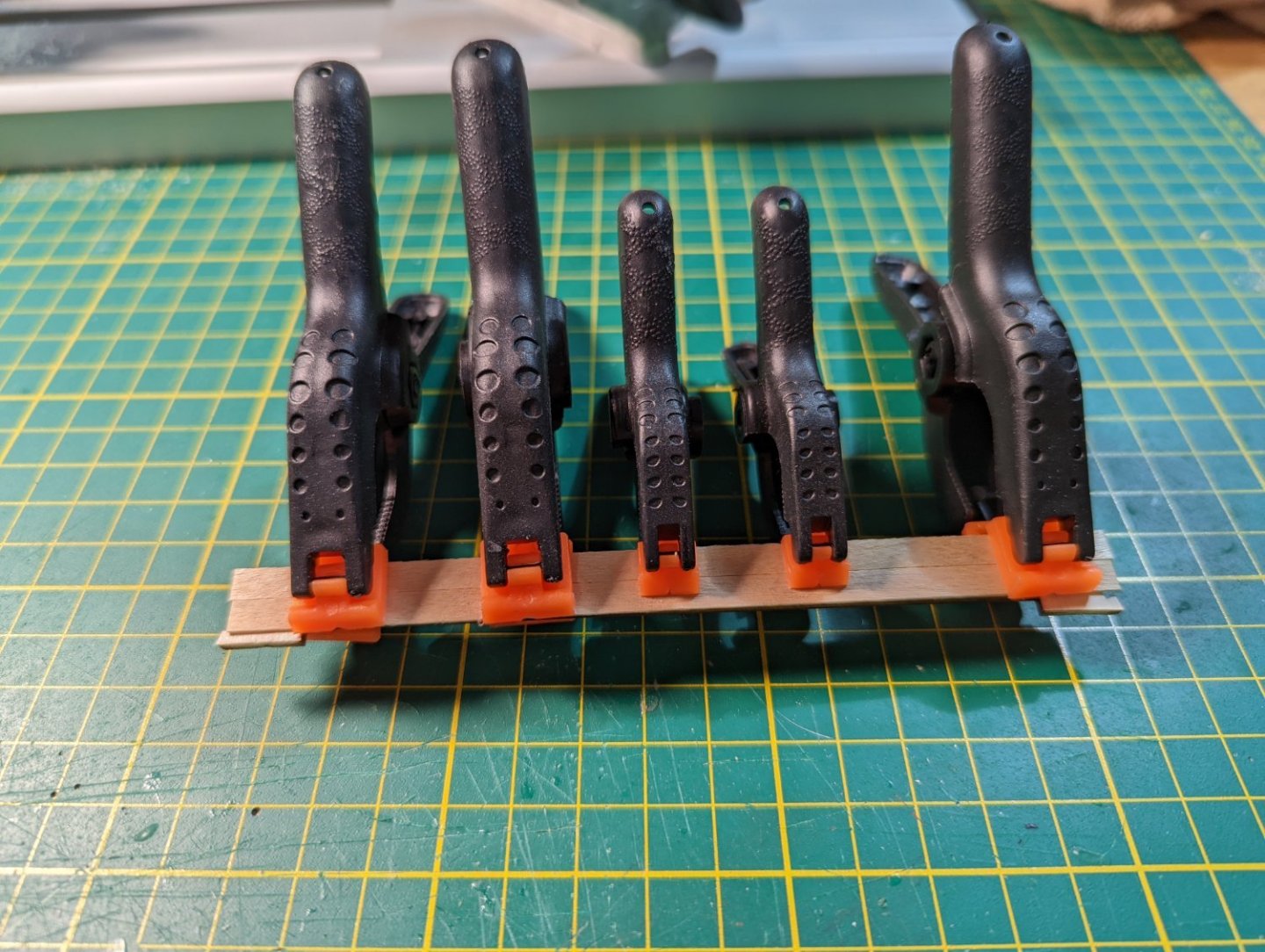
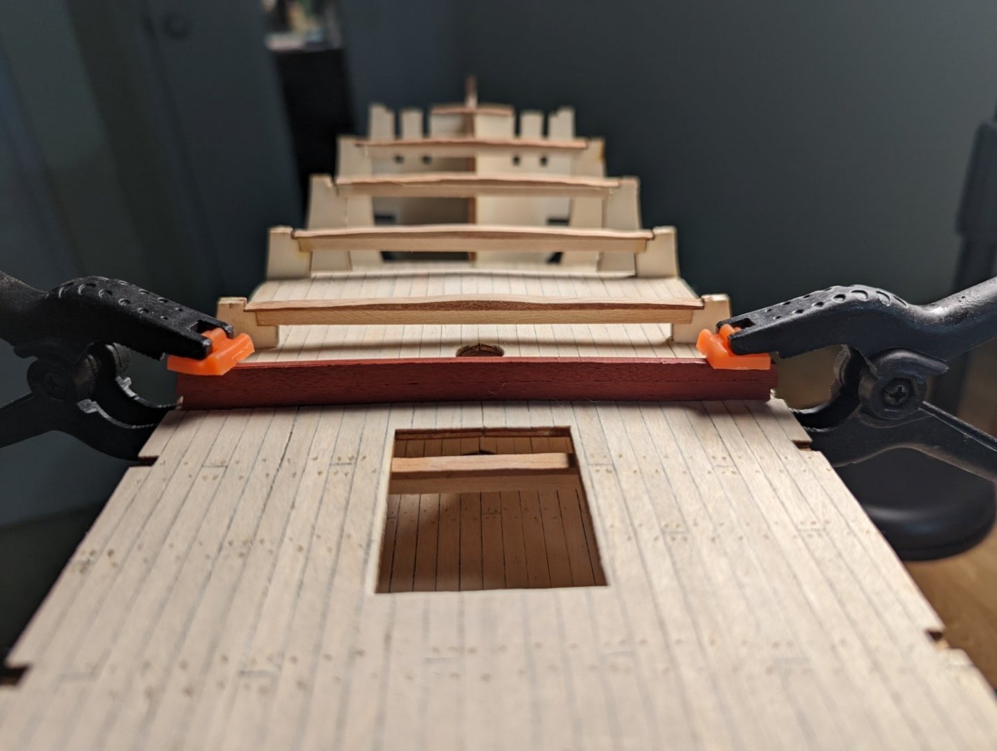
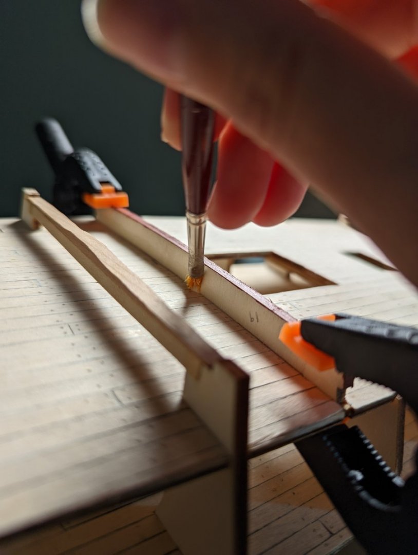
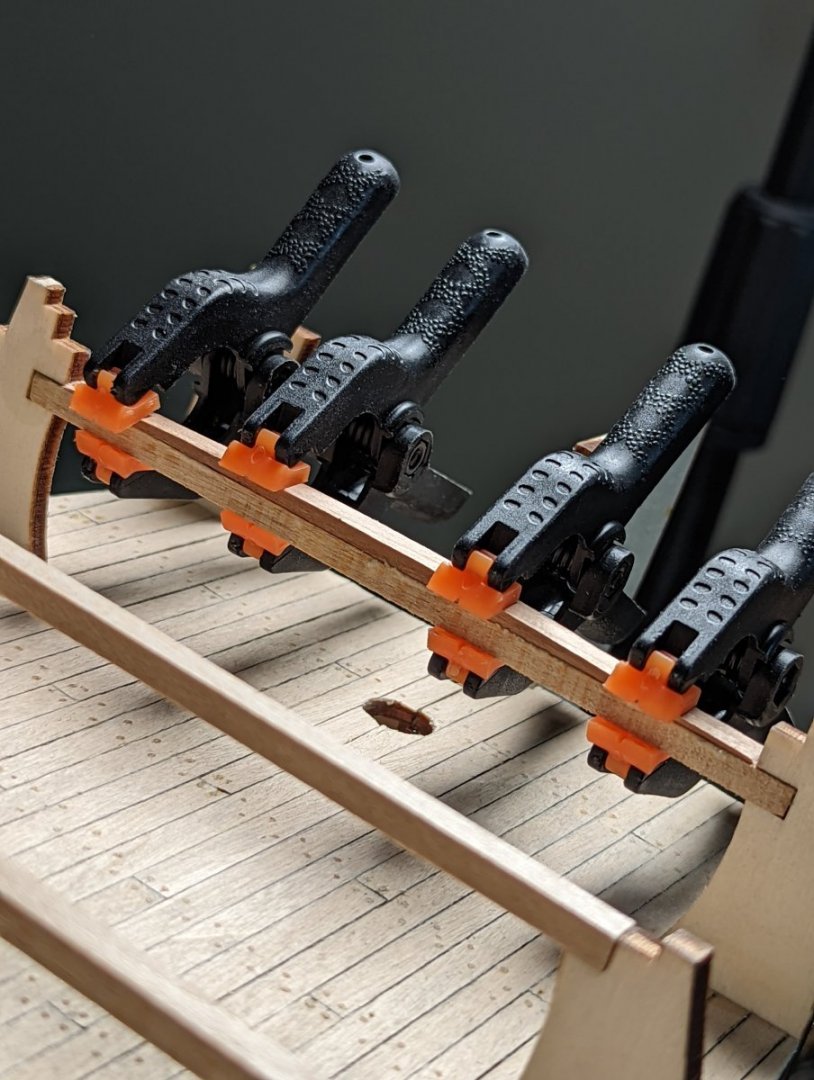
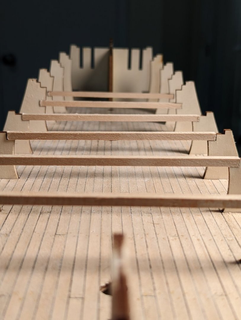
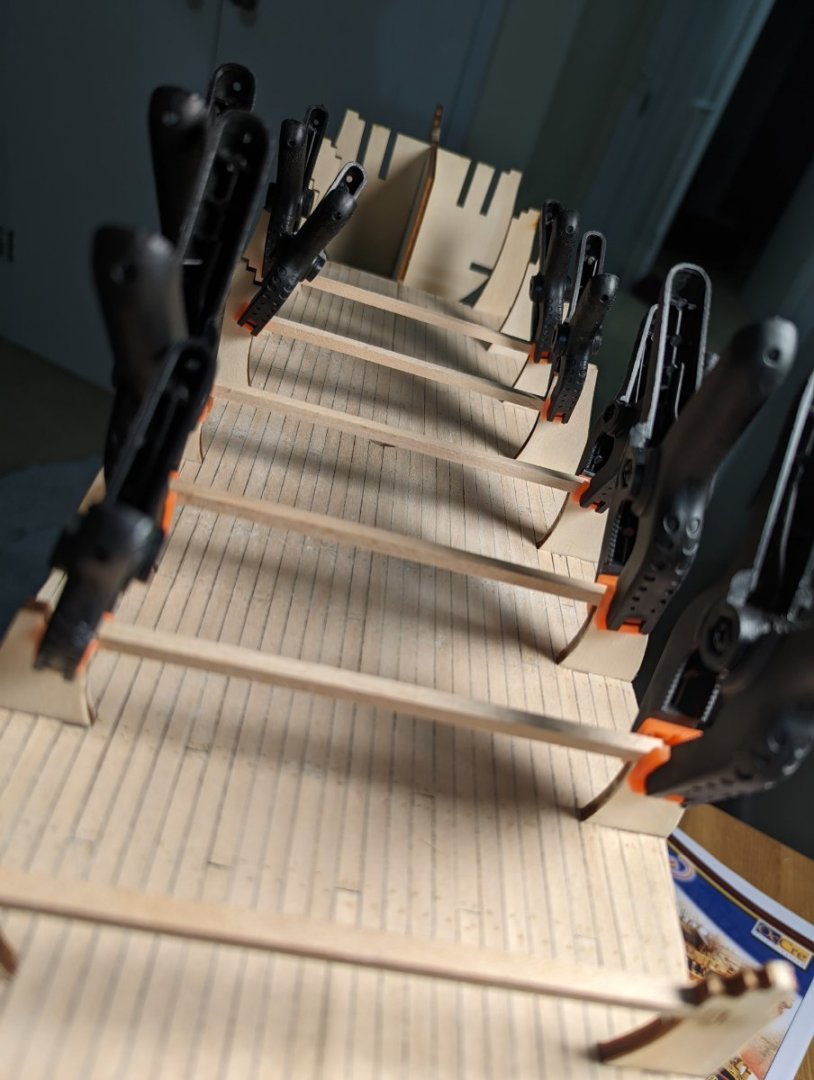
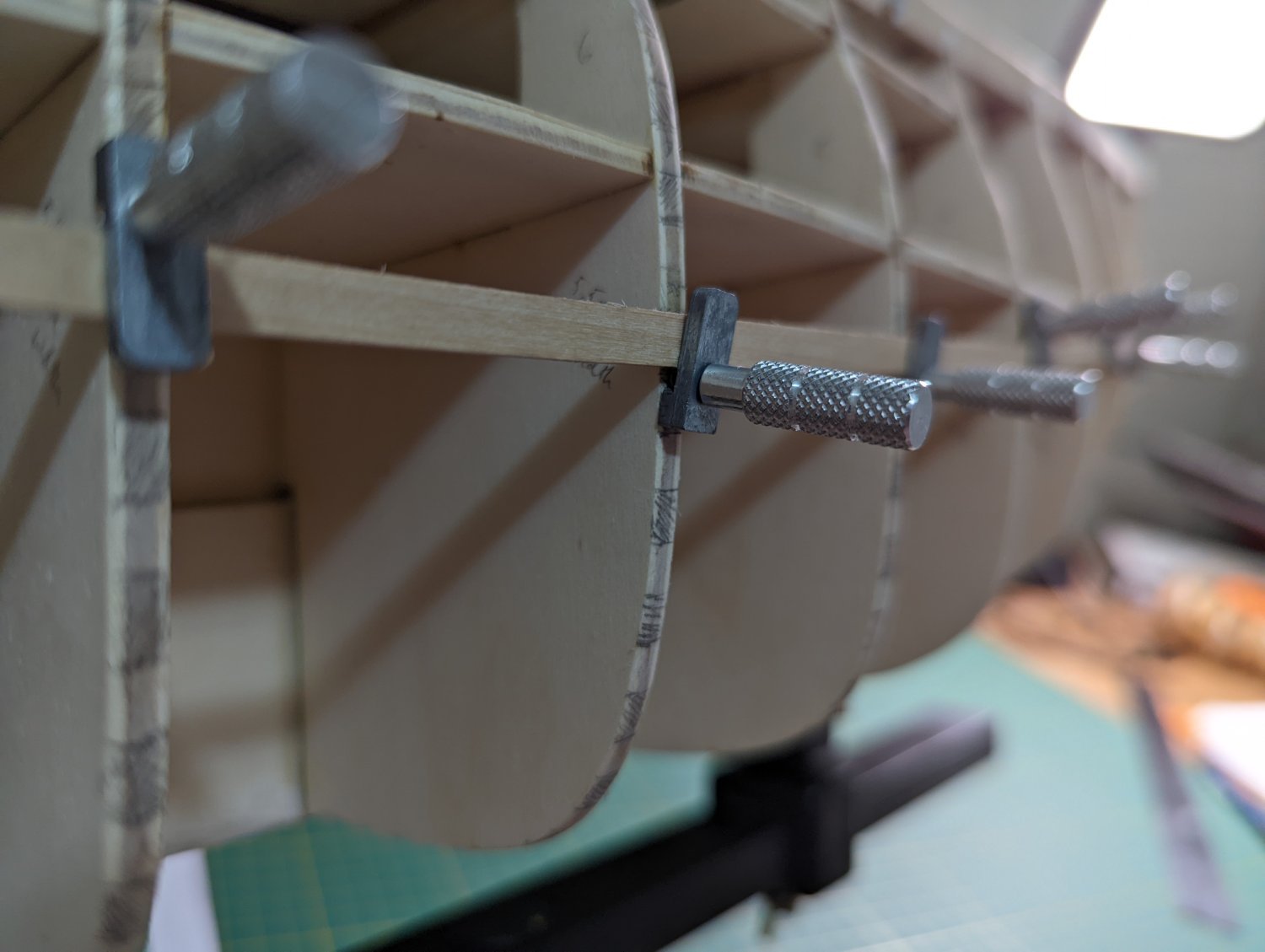
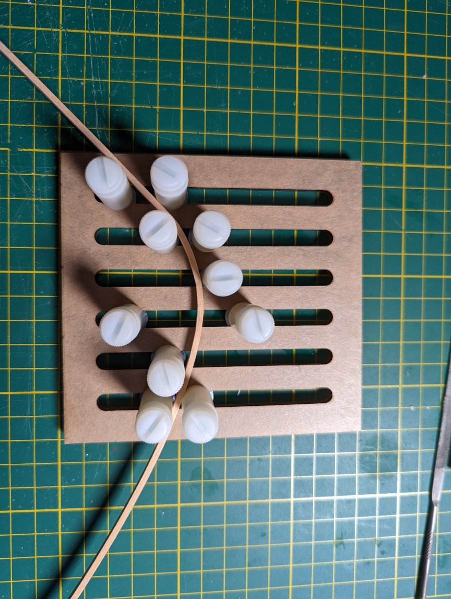
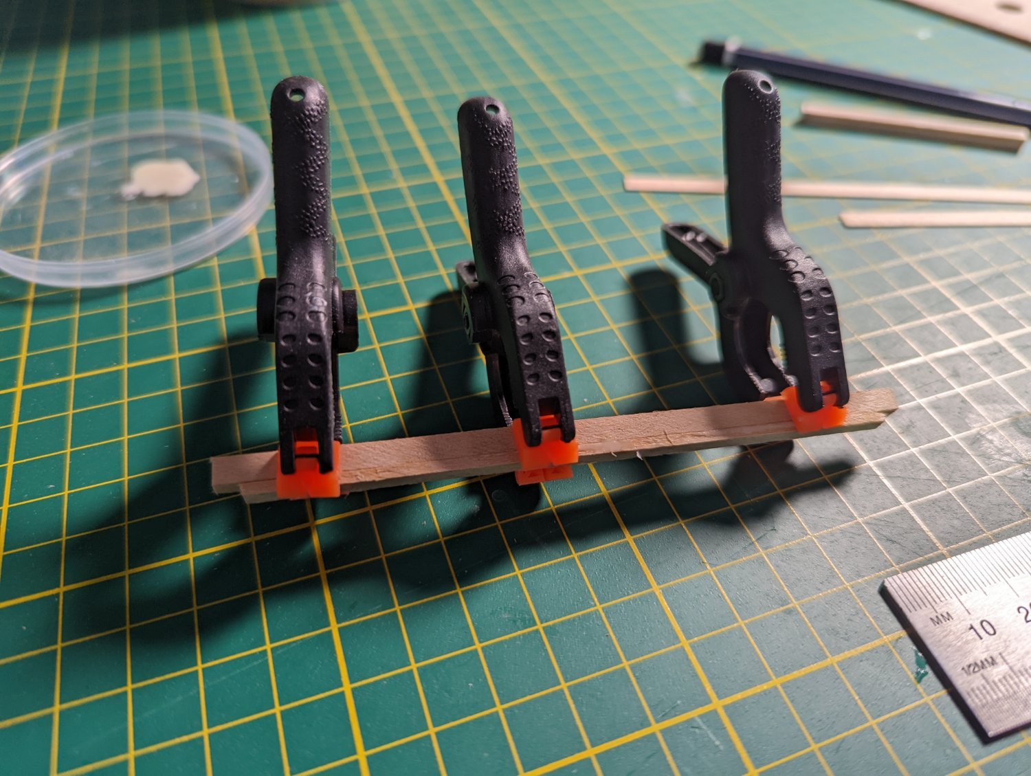
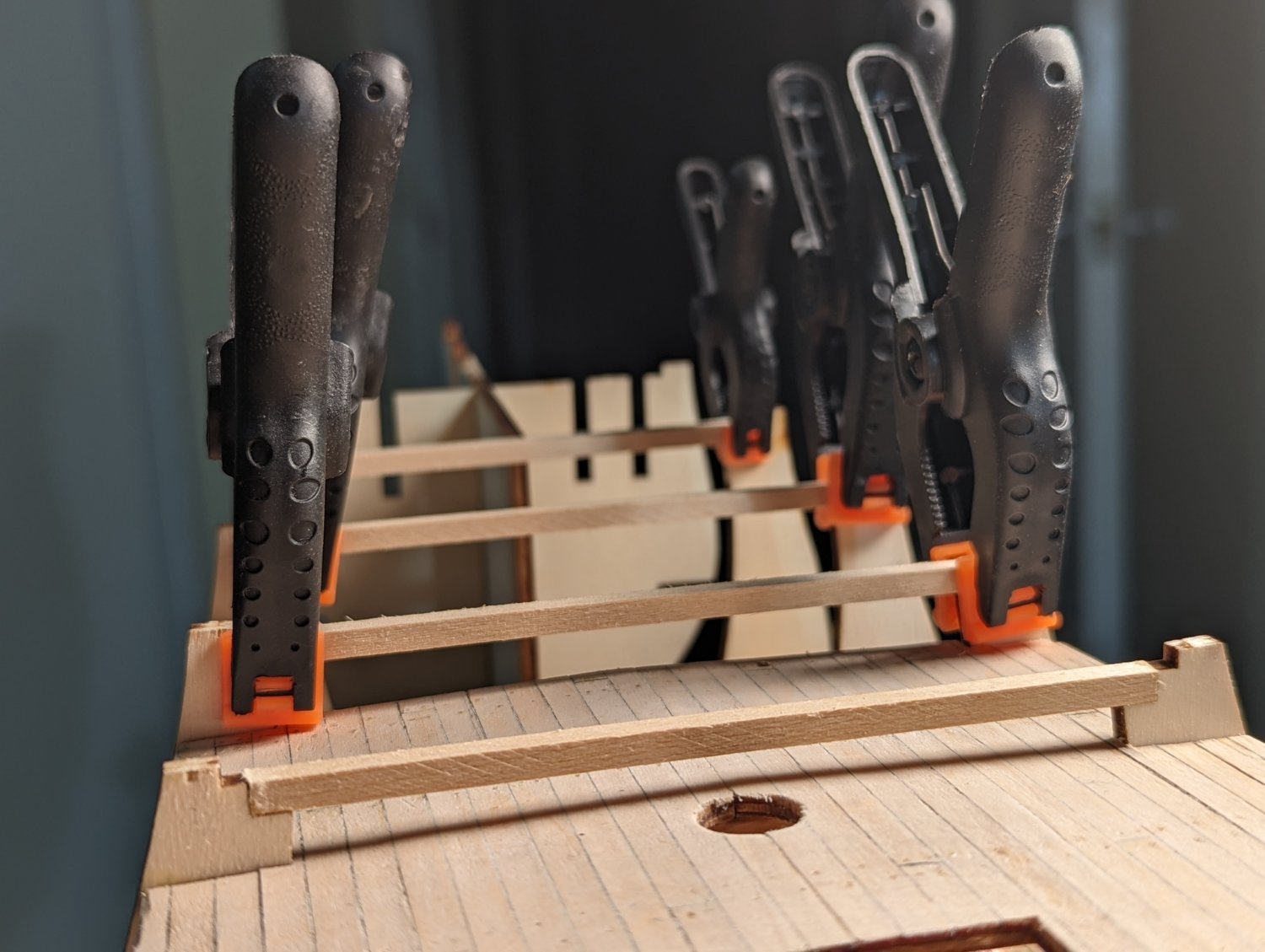
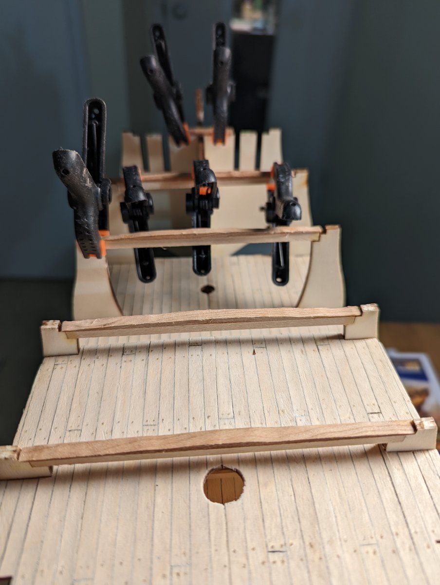
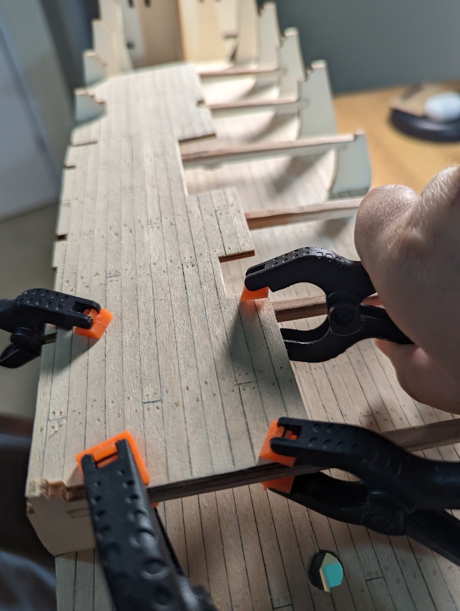
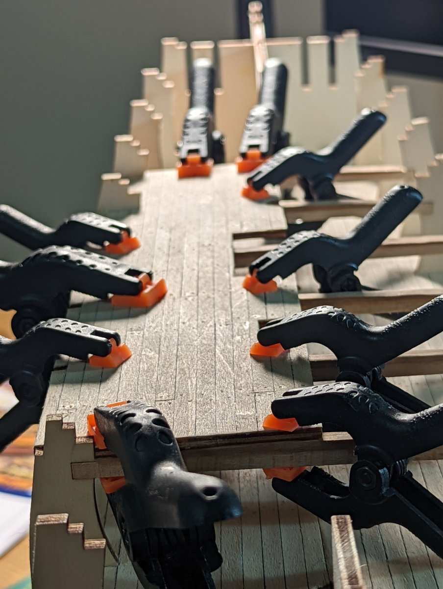
I previously bought some screw plank clamps for my first model which I employed to clamp the first plank to the hull: the line of the wale.

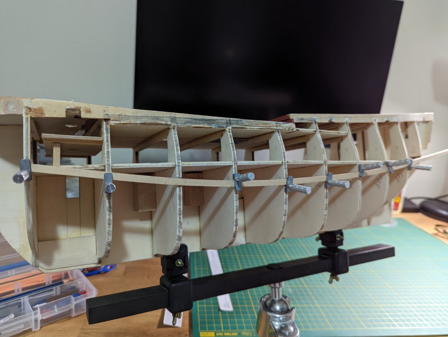
And that's it for the night! I haven't even done the starboard side yet! I'm trying to take this slow and methodically as I know good set up will help with the final result.
AN ODD COINCIDENCE...
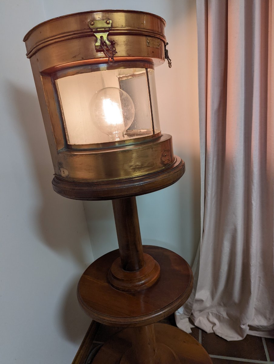
I went on holiday with friends last week and the farmhouse we stayed in was evidently the home of a similar historic maritime hobbyist.
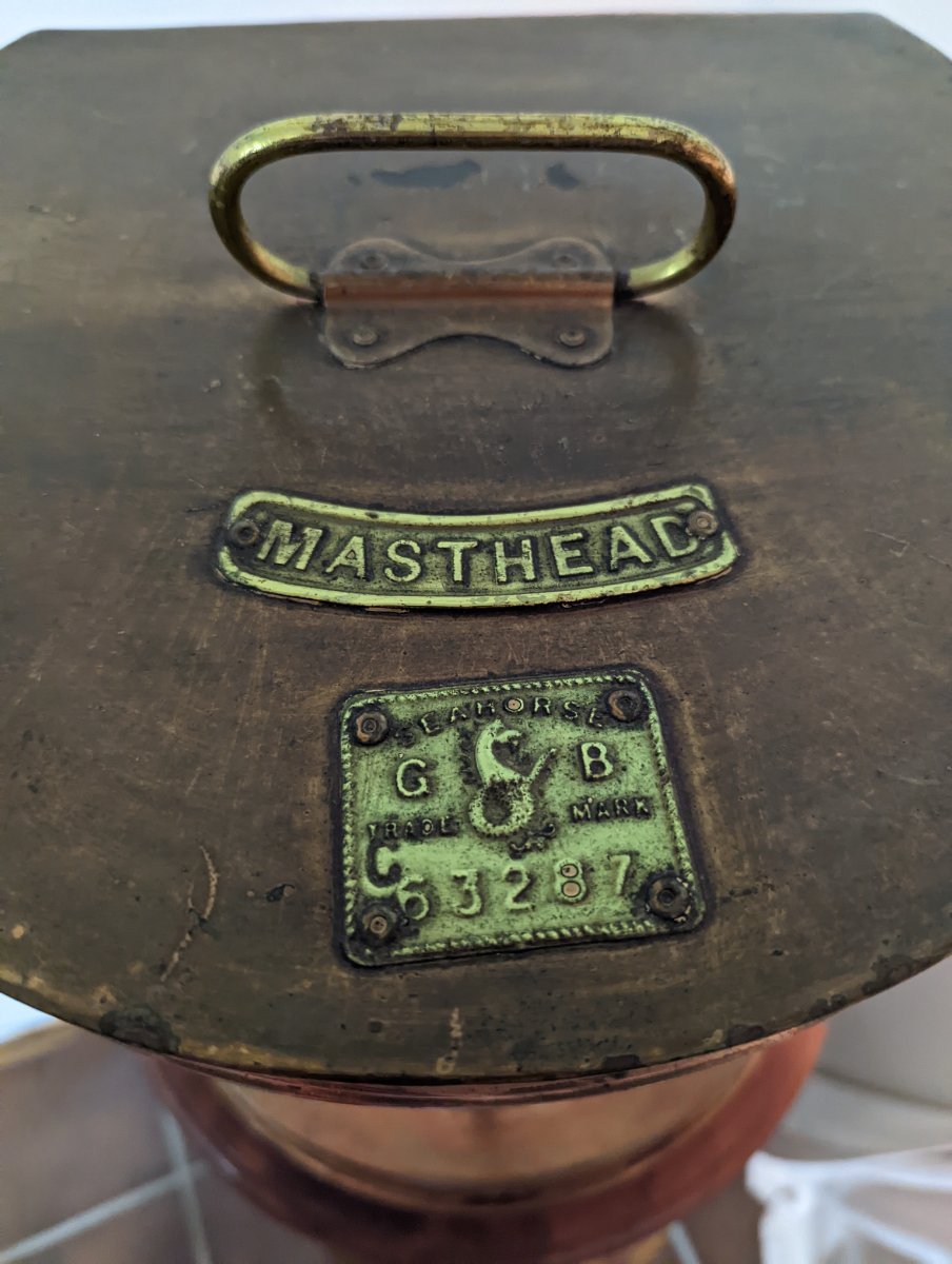
On display included a fully fledged cat o' nine tails, ship's compass and light. The cat was quite ominous in person!
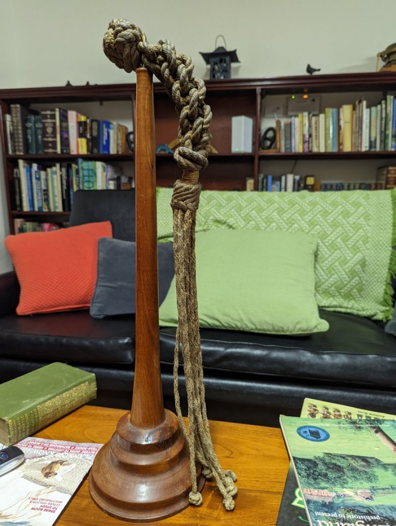
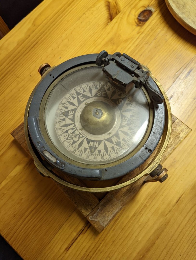


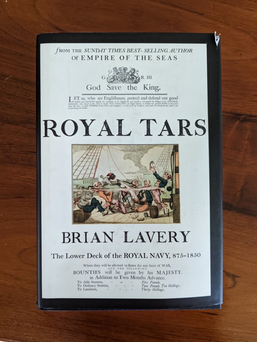
They also had a great library which included a very cool book on the lower decks by Brian Lavery. This author, on my inspection, has written not one but several interesting books on model ship construction for ships of the 17th to 19th centuries.... to one day add to my growing collection!

- GrandpaPhil, ccoyle, Dave_E and 1 other
-
 4
4
-
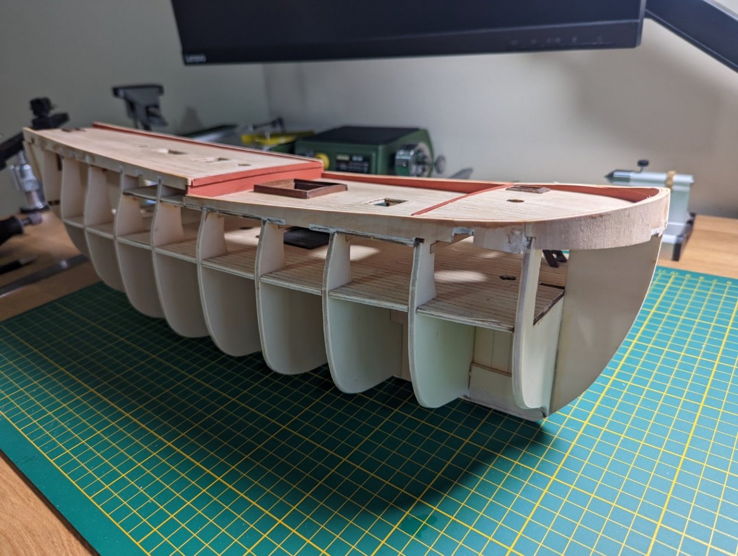
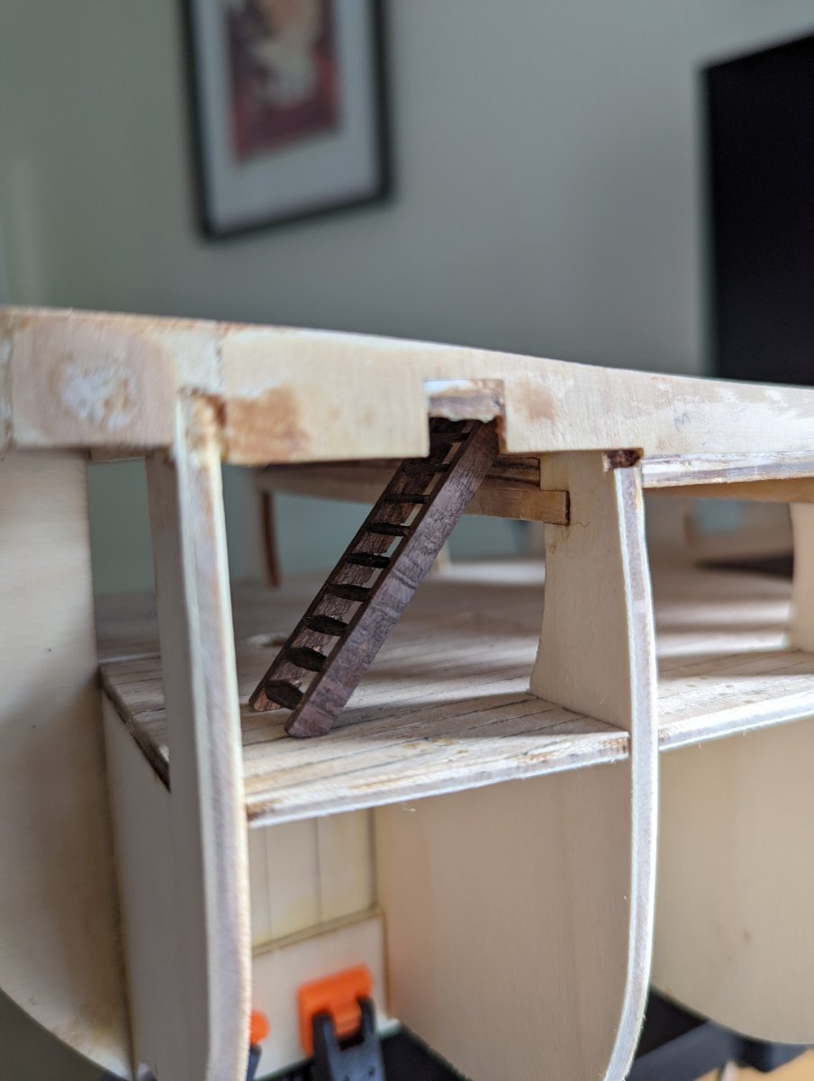
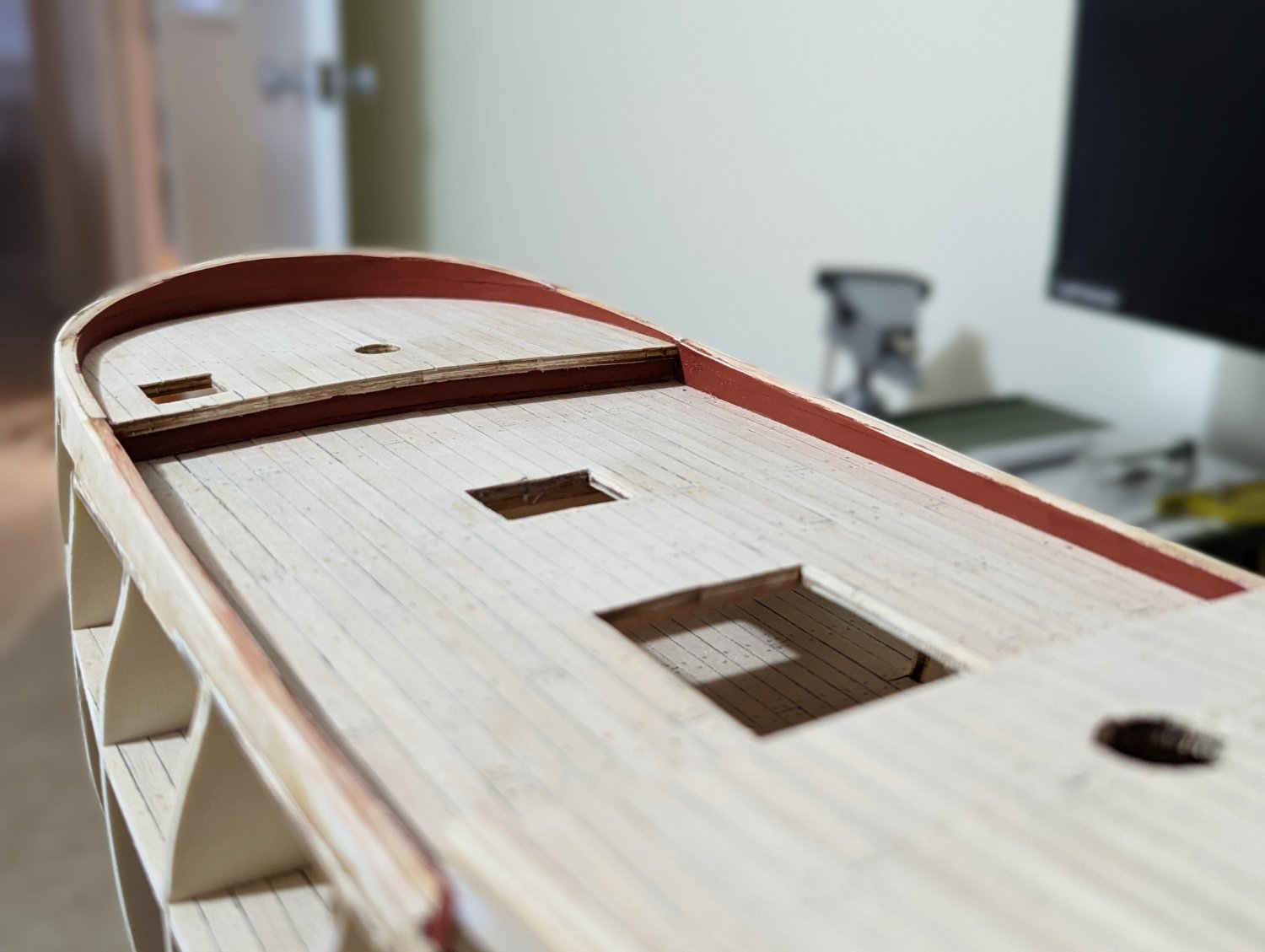
ADDING A TWEEN DECK UNDER THE FORECASTLE DECK
I amended the forecastle hatchway stairs to drop down to a scratch built tween deck (I think tween deck is right?) between the lower and forecastle decks.
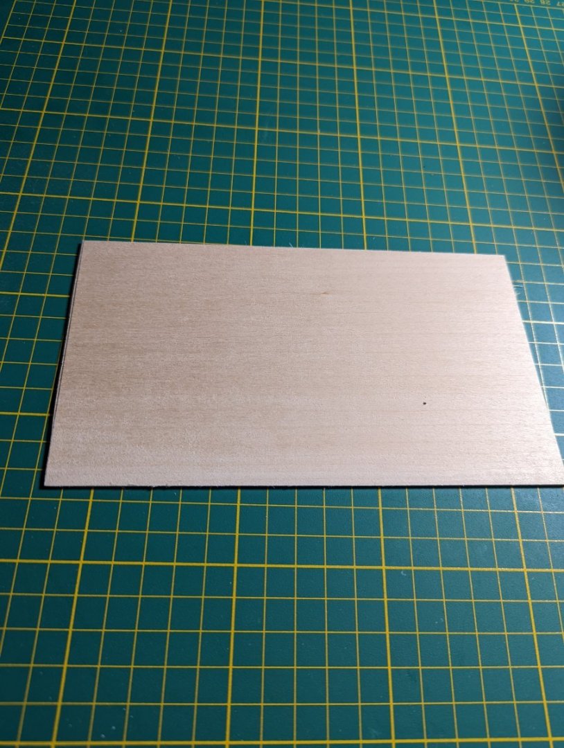
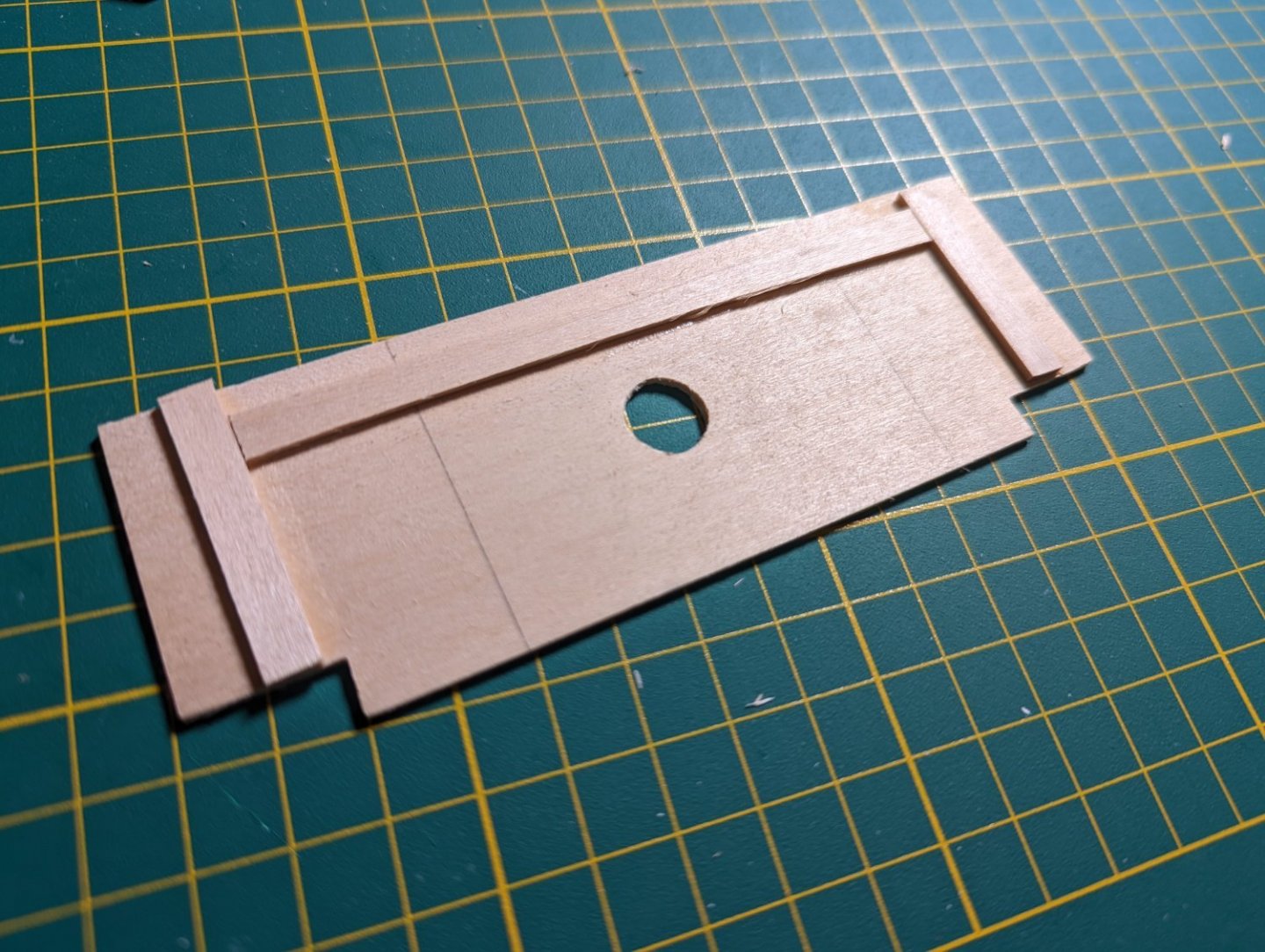
To do this I rigged up a deck platform from spare 5mm boxwood sheet.
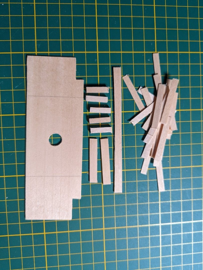
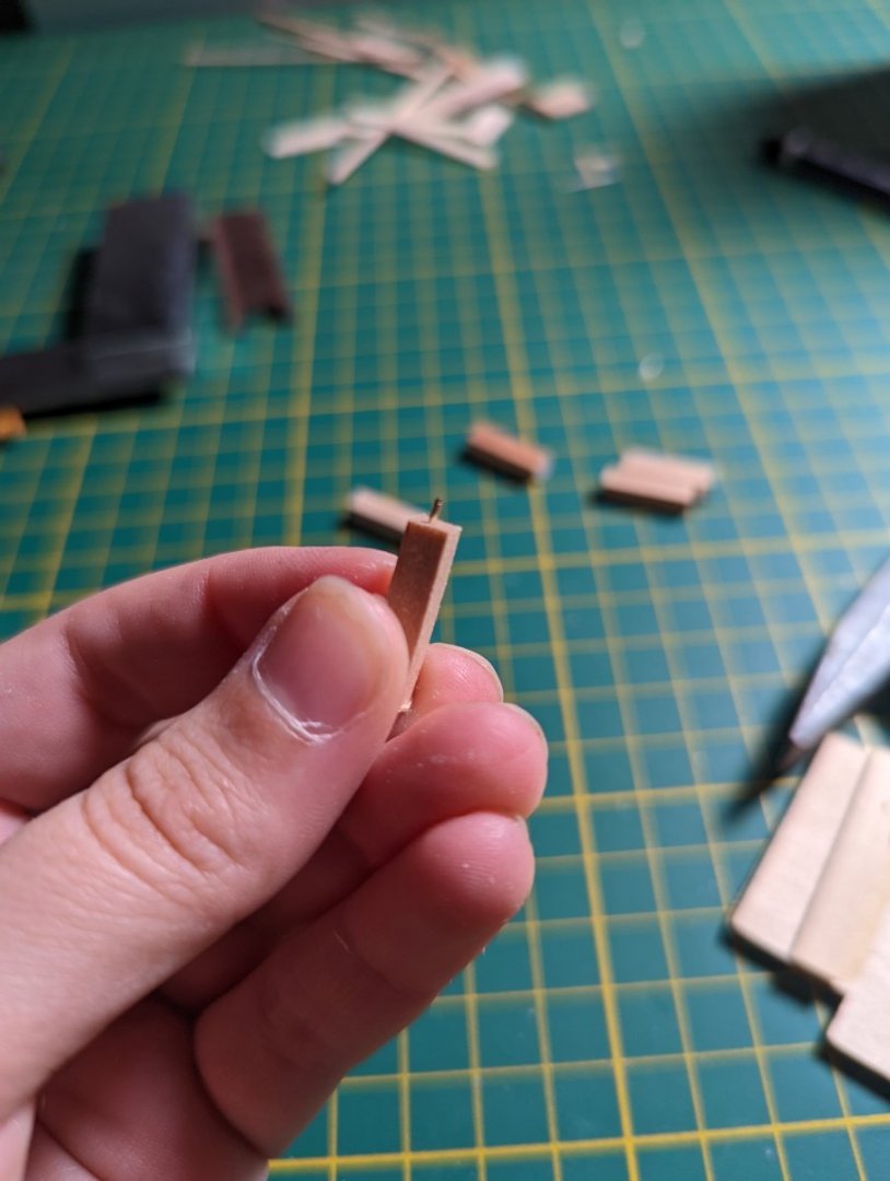
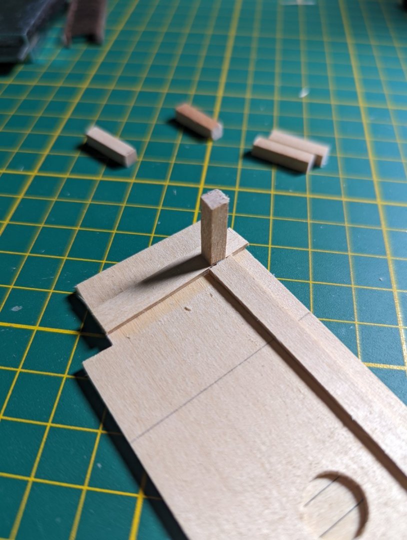
I added some support beams underneath and two feet to which the deck is attached.
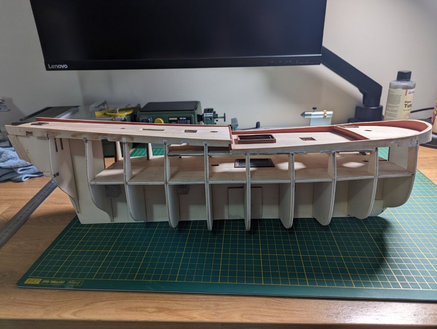
To keep these feet in place, I used cut nails and Titebond glue.
I planked the tween deck, making sure to cut out the foremast hole.

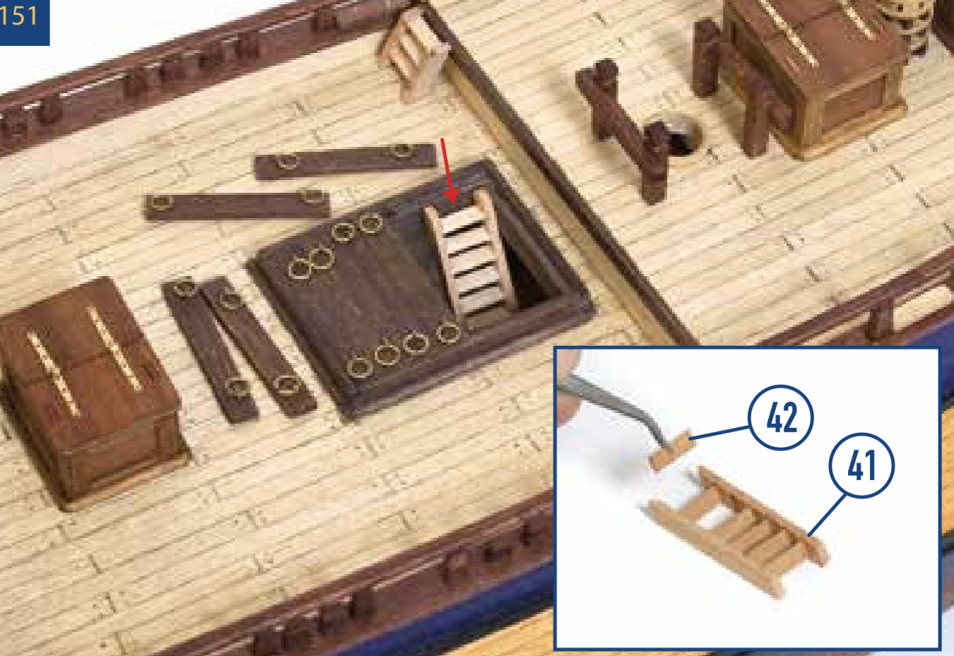
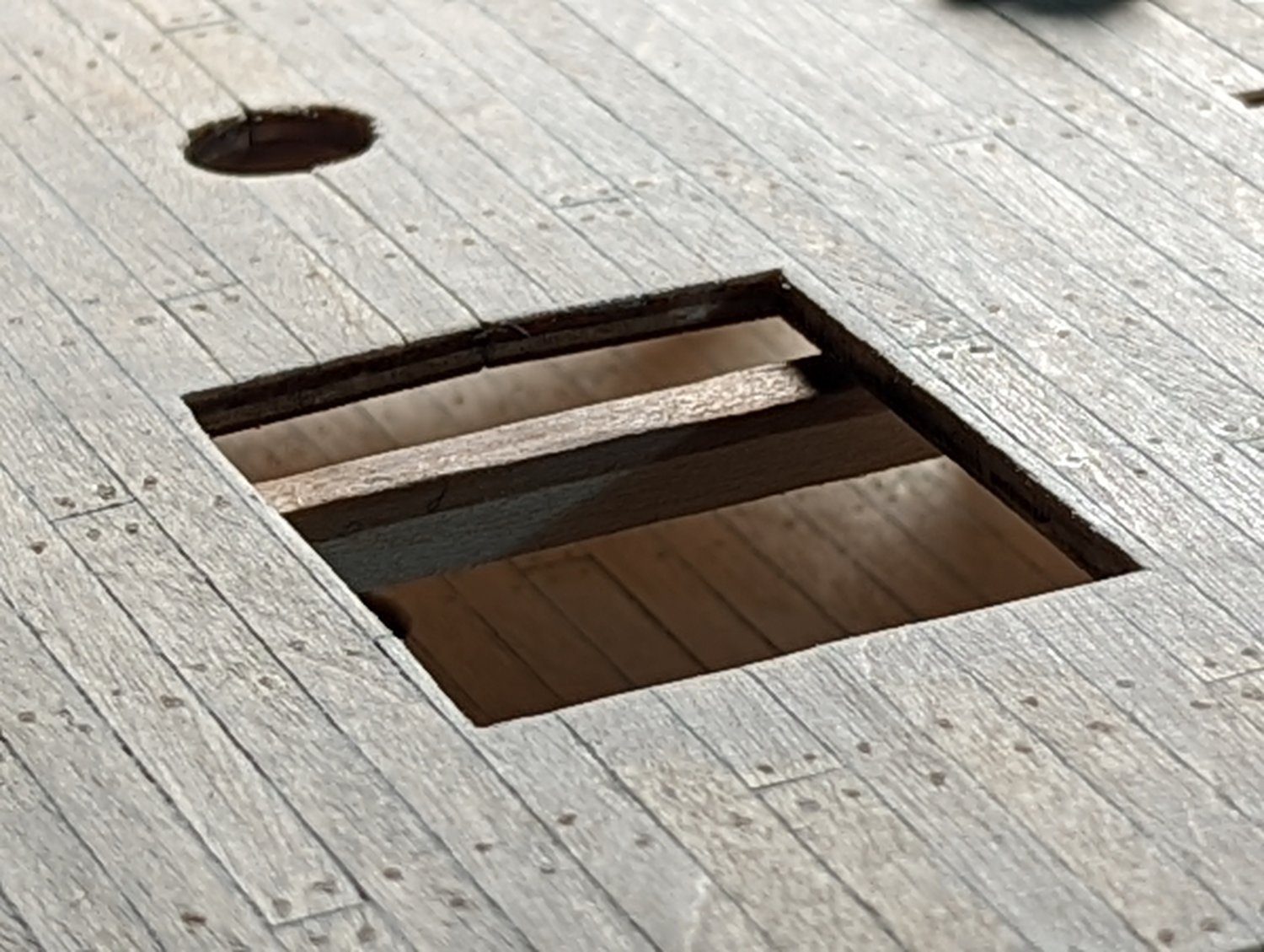
I installed it in place and added the trimmed ladder. Et voila!
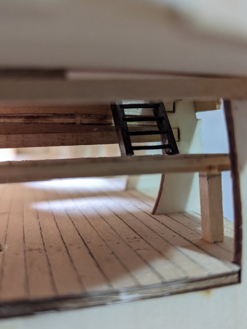
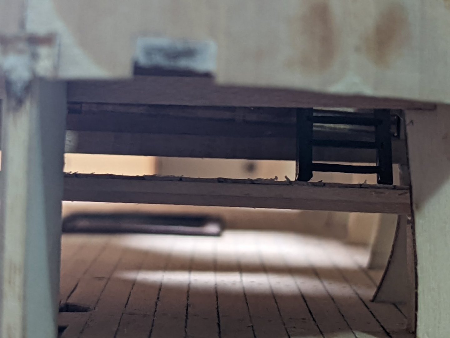
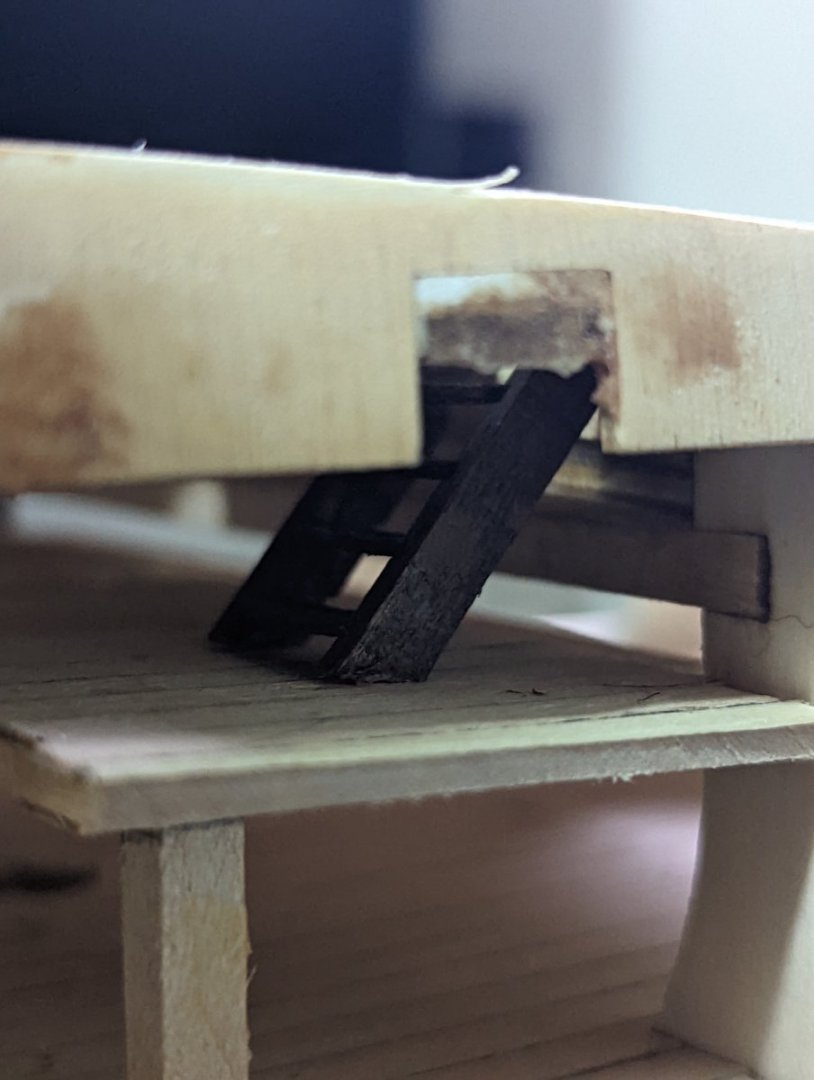
Now when I peer down the forecastle hatchway I'll see the deck.
Thanks for the idea, Steve!
- Prowler901, GrandpaPhil and Dave_E
-
3
-
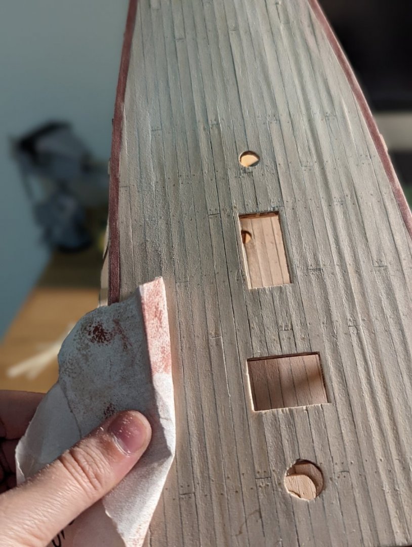
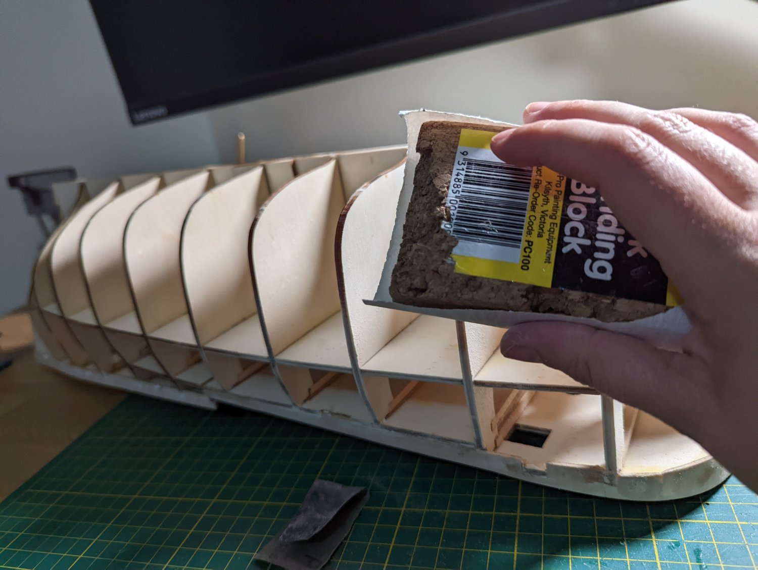
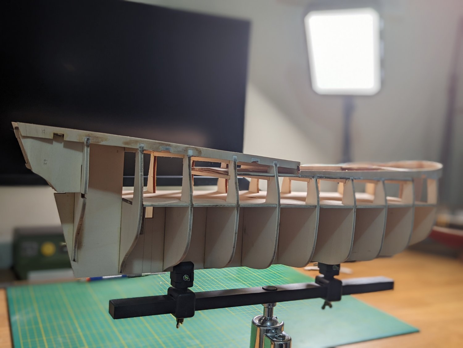
STARTING FAIRING THE HULL
By far and away my least favourite part of building - due entirely to the sheer amount of sawdust this creates - I started fairing the hull this afternoon.
Everything in the study is now covered in a thin layer of sawdust and the Admiral has called me to their Cabin for a sure dressing down!

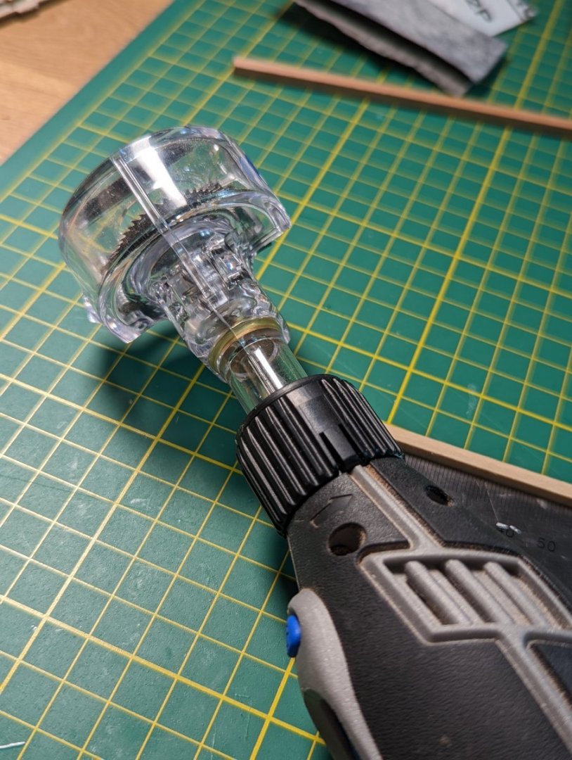
The mess aside, with the help of my Dremel and a sanding block I took to this process with zeal.
I'm sufficiently happy with where I've landed for the day.... but much like anything good, I'll revisit over the following days. I want to double check and ensure smoothness, particularly on that bow, as good preparation here will make or break the final product.
The buff bow on this bark mean that the instructions call for a filler block to be sanded down to the bow and no first layer of planking used... I wonder whether it'd be tenable to plank the whole first layer.
I've linked a post from another OcCre Endeavour build (from kiwiron) that shows what I'm talking about. Here, you can see the first planking layer ends before the bow.
Example hull planking from Kiwiron's Endeavour build
Will wait and see what approach is best for this kit after some research.
I will also look to drill and add some holes in the keel to support the stand supports. I'm still doing some background research on the best steel rods or screws to use for this, but this will be a separate post.
- GrandpaPhil and Dave_E
-
2
-
Gosh, it is VERY tempting to follow suit, Steven and add that extra layer of decking before I close the hull up.
Given I'm waiting on Chuck's gratings to arrive from overseas there's no pressure to push on with planking the hull....
Again, I'm going to steal from that amazing build of yours! Many thanks!
-
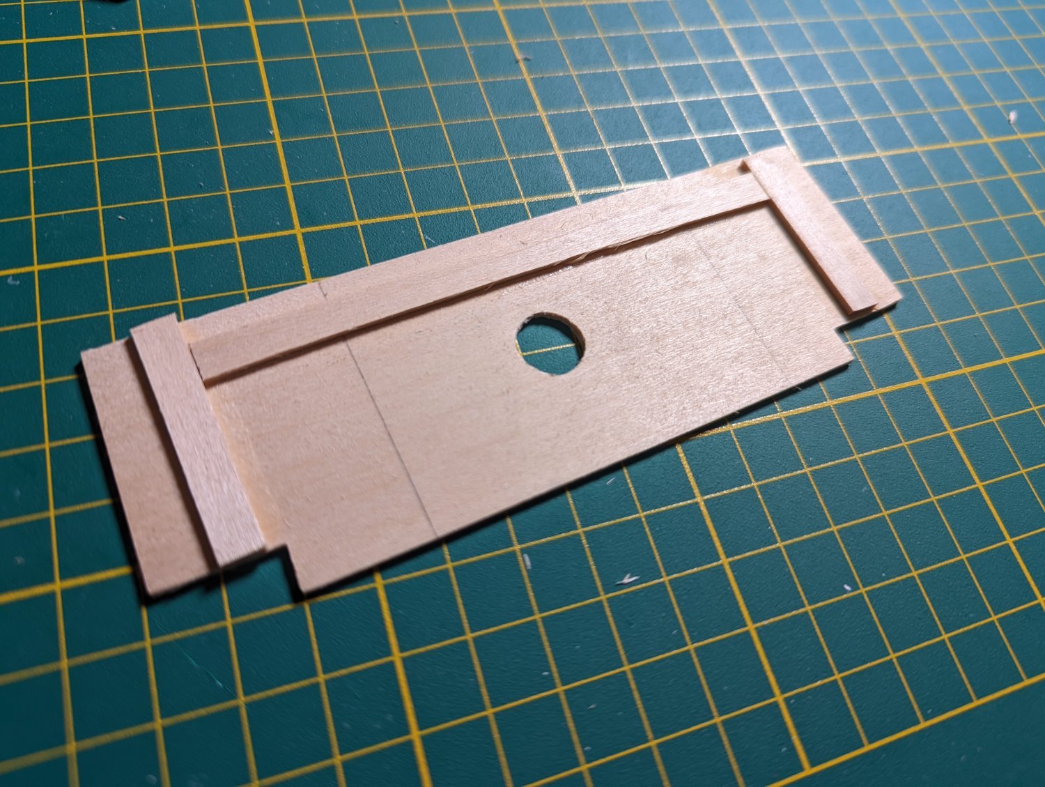
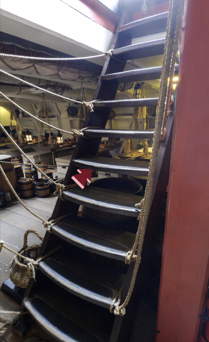
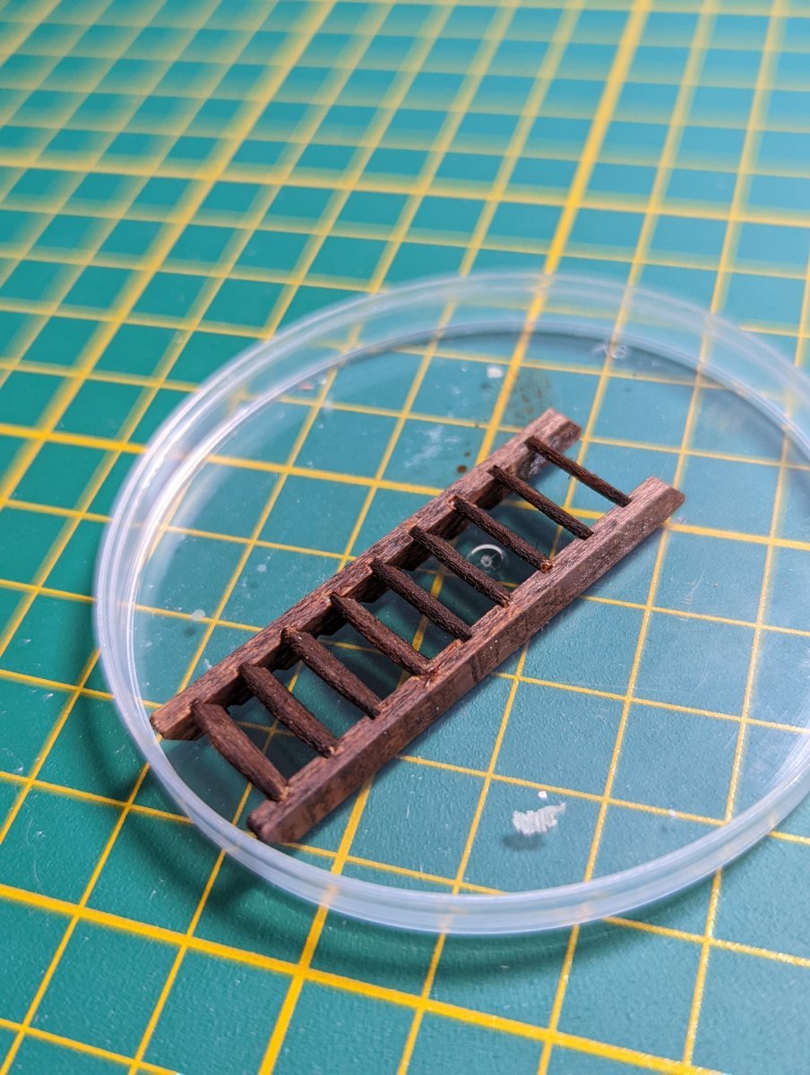
MAKING STAIRS
The OcCre instructions call for stairs leading down from the forecastle hatchway.
Much later in the build I'll be building more stairs. The kit suggests to build stairs down from the main hatchway, which I won't follow.
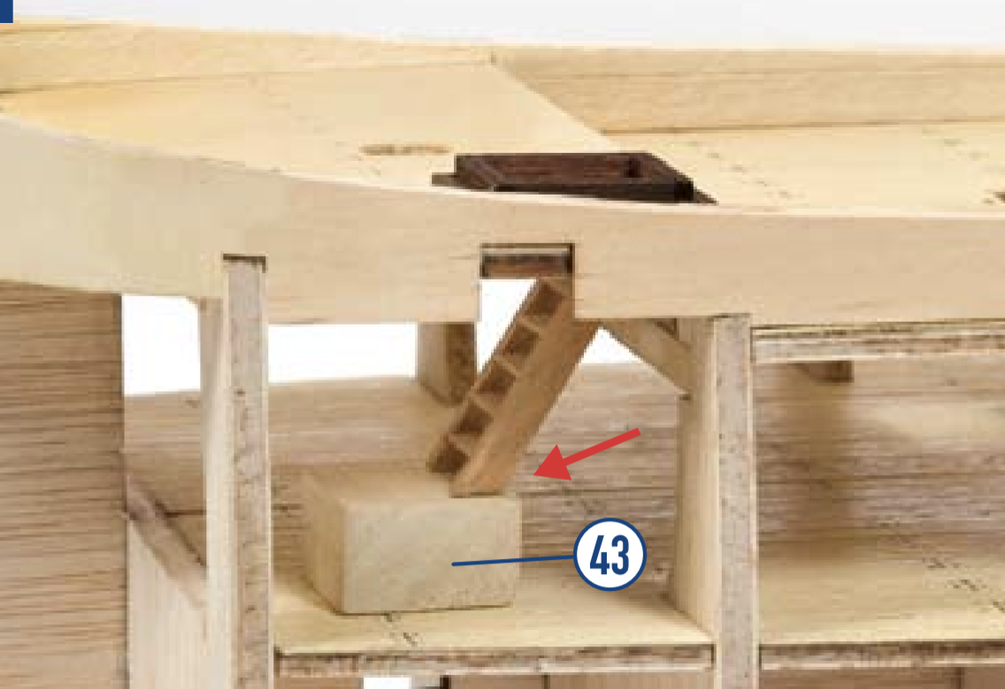
The OcCre kit has the stairs only go down halfway to the lower deck, before they recommend you install a lump of wood (part 43) to meet the floor. I figure if you're going to go to the trouble of making stairs, you may as well finish the job. I'll deviate from the kit instructions slightly.
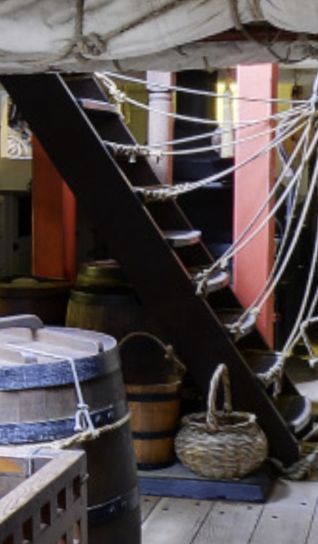
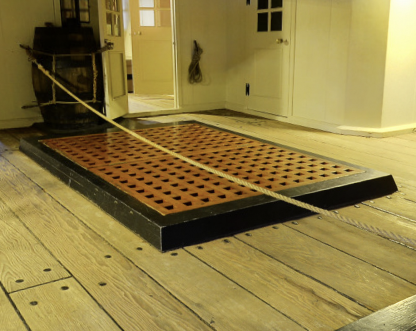
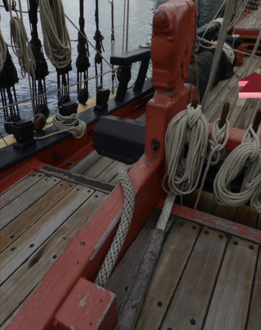
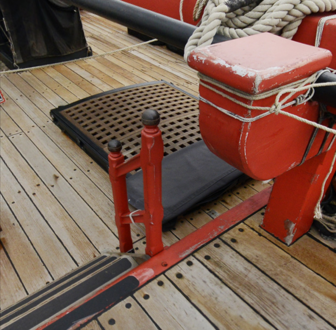
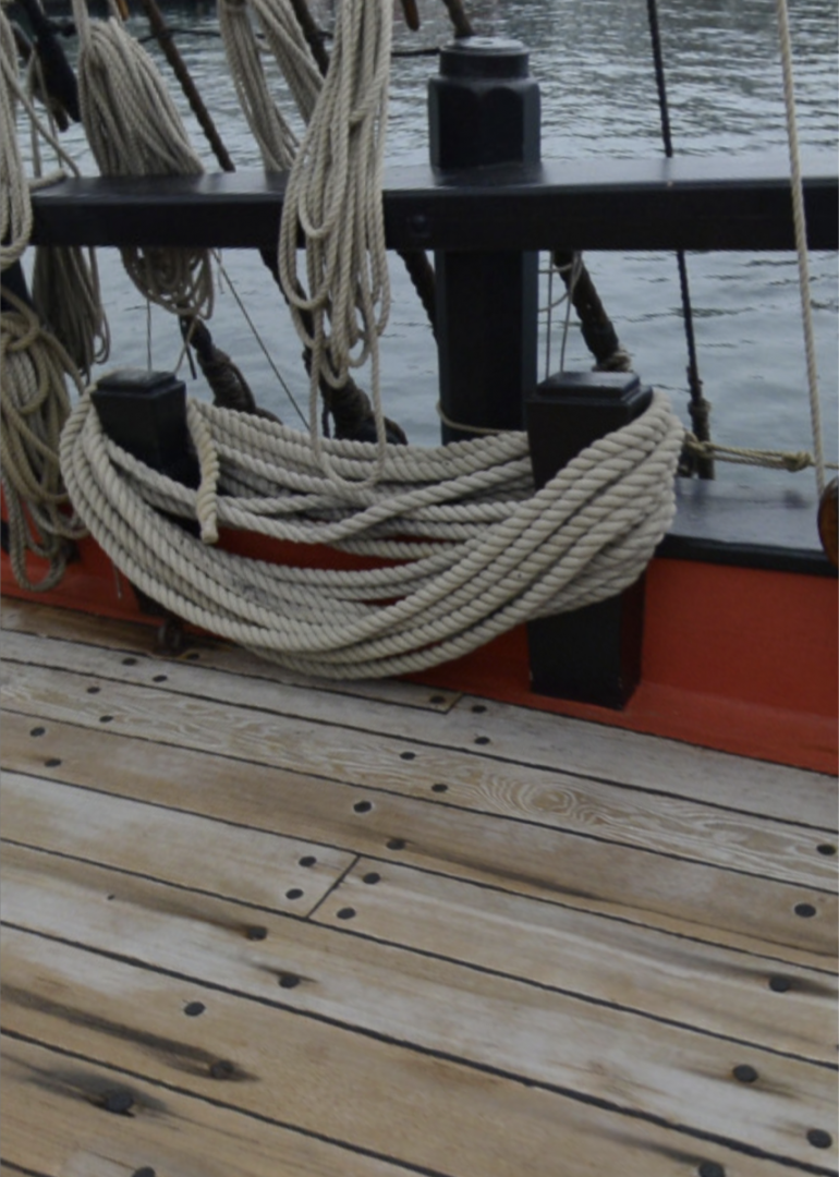
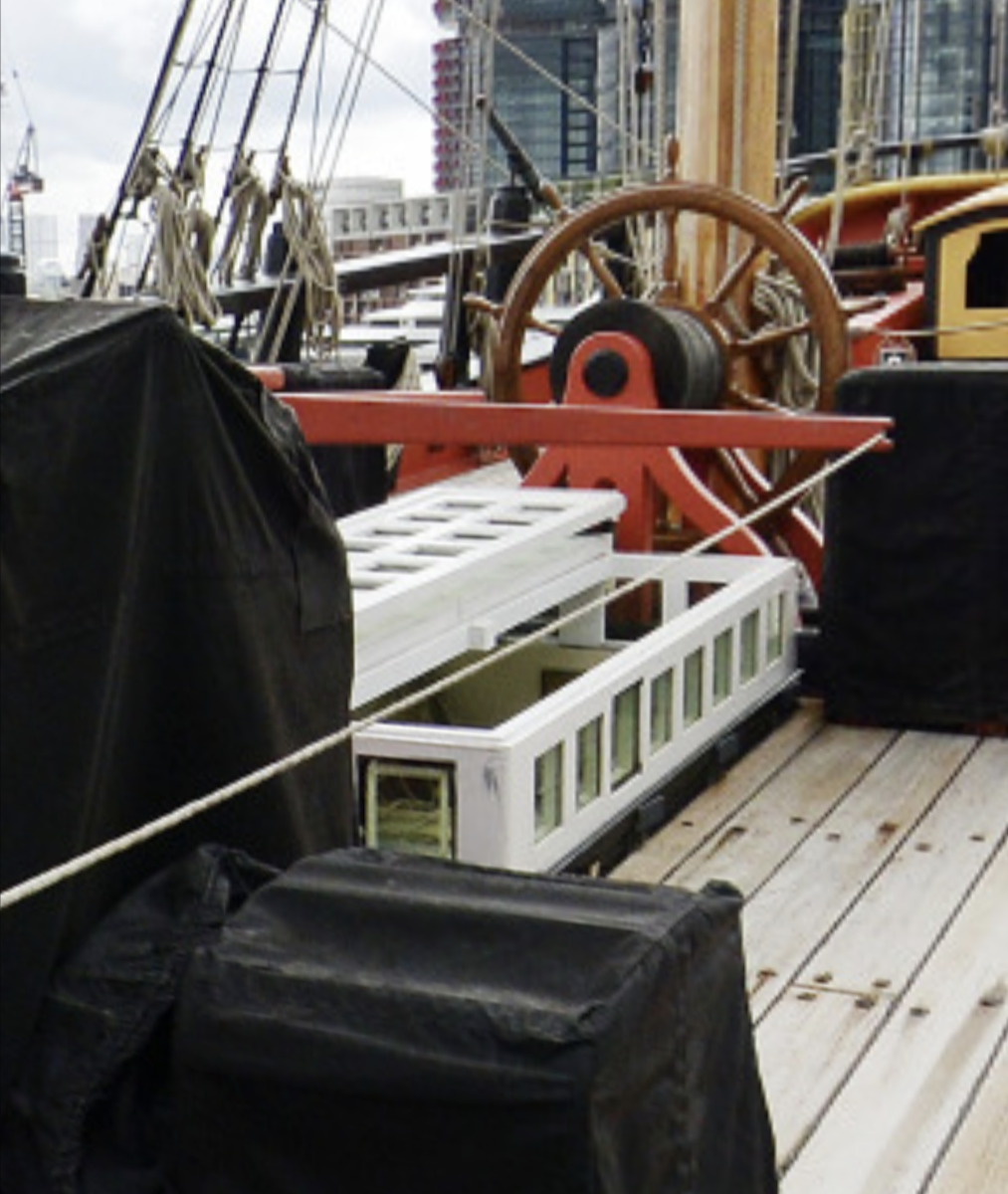
I checked out what the stairs look like on the replica. A couple of notes from me - the steps themselves are rounded towards the front (mental note) and the stairs throughout are dark wood painted (also noted). There are also some rope rails which I won't include as they won't be visible.

I read up from The Anatomy of Nelson's Ships on how best to make stairs, but then I checked the parts that came prefabricated with the kit, and was pleasantly surprised.
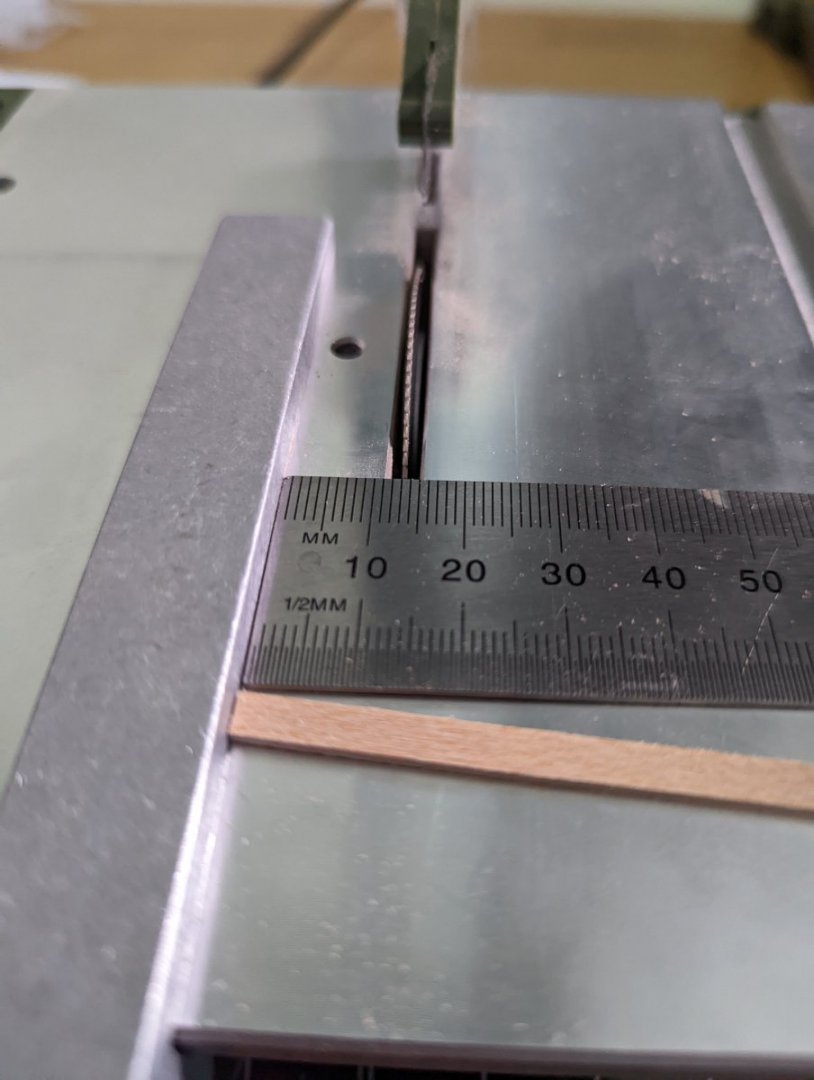
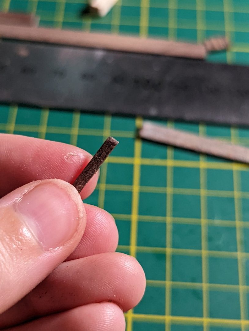
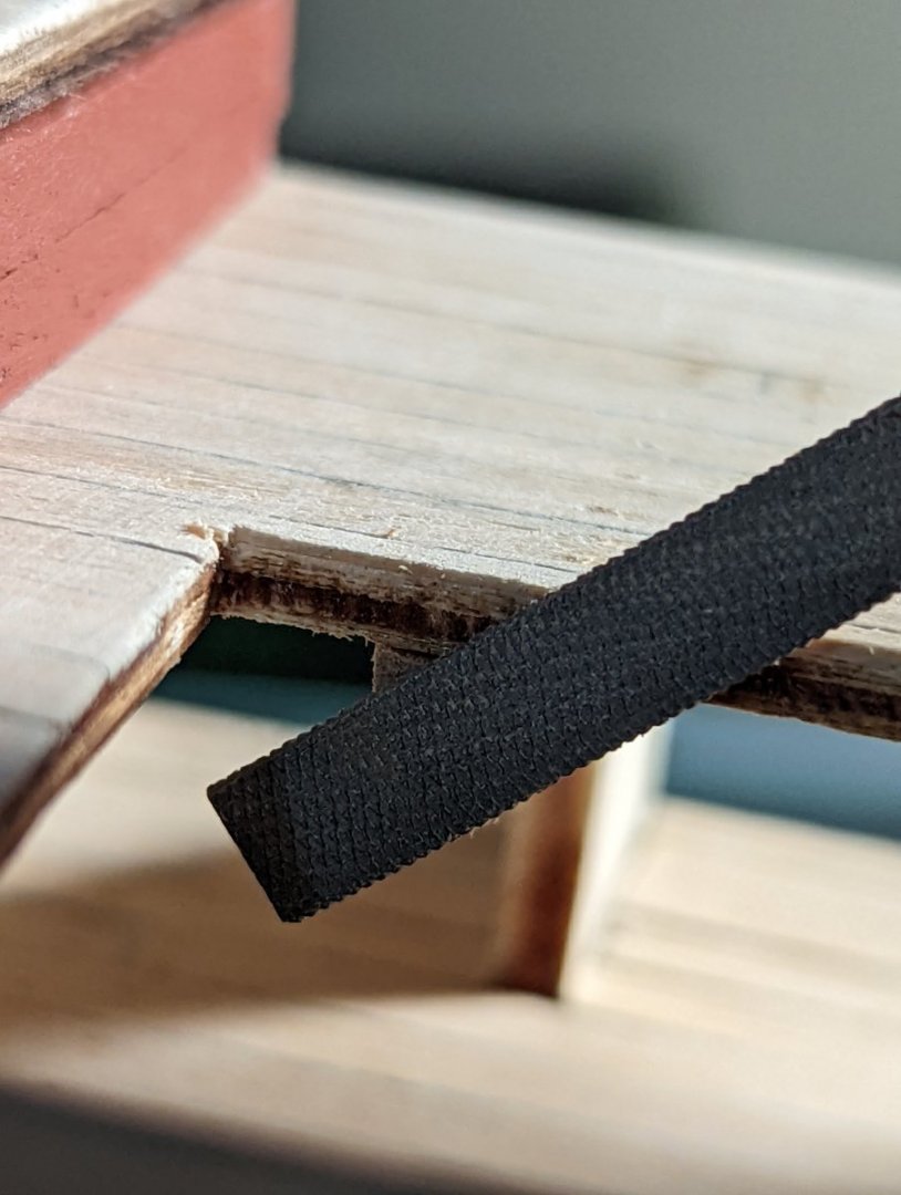
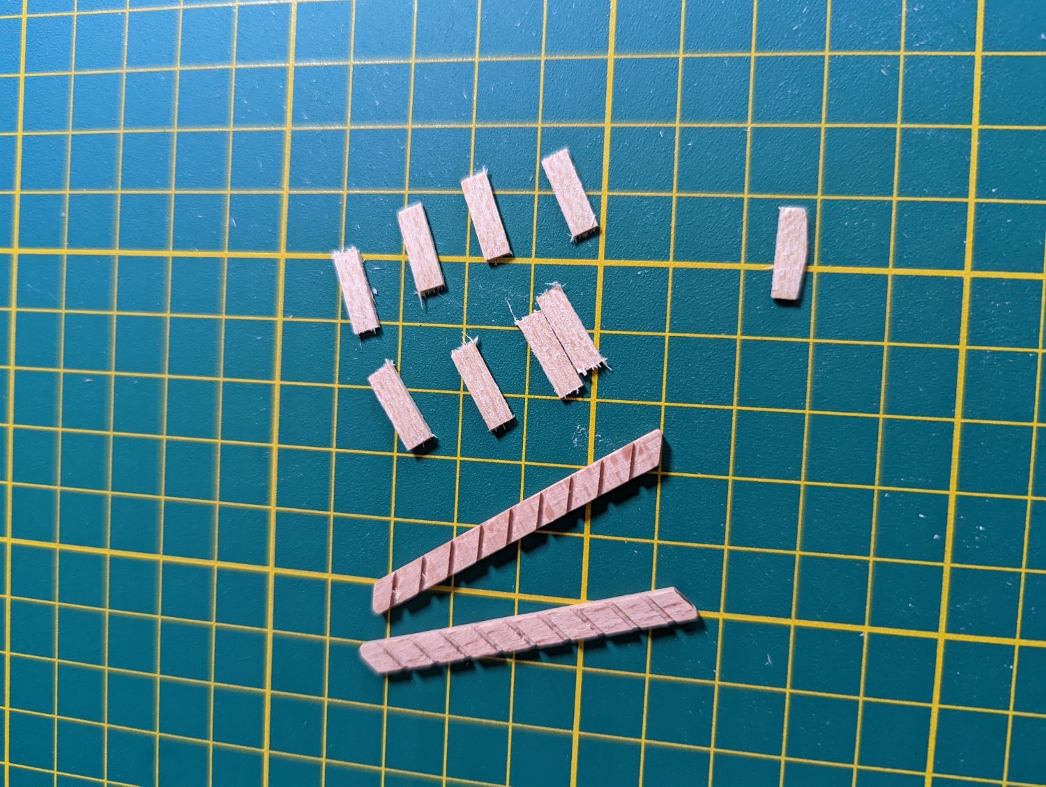
I used my table saw to cut steps 12mm wide.
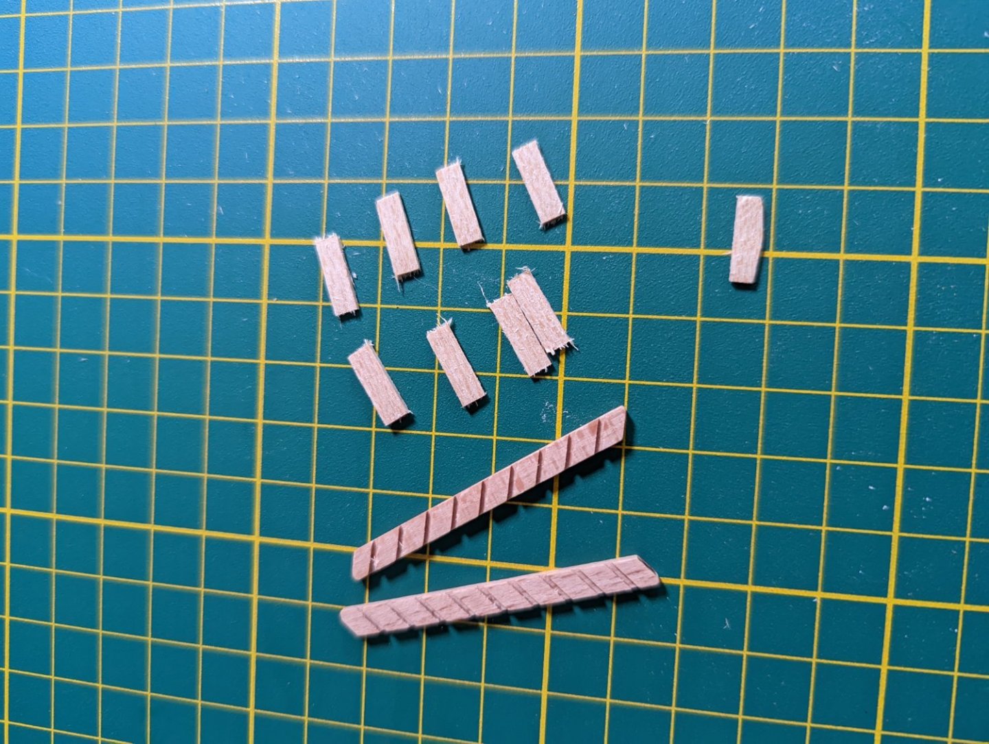
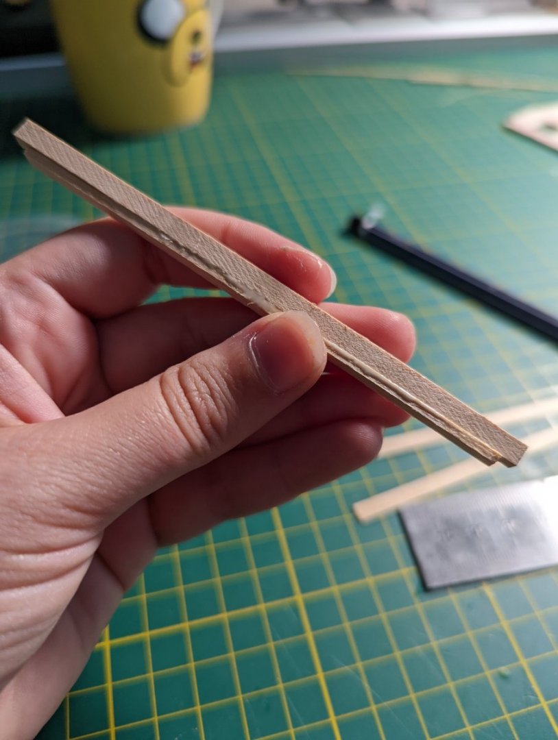
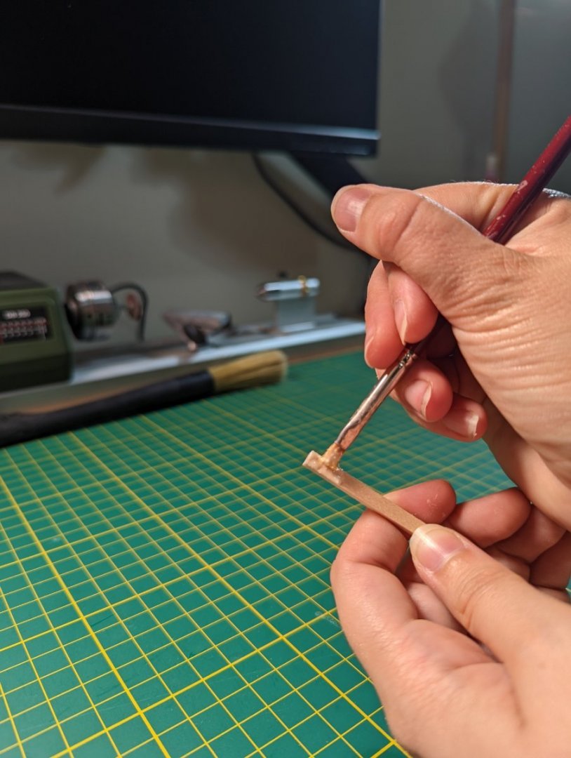
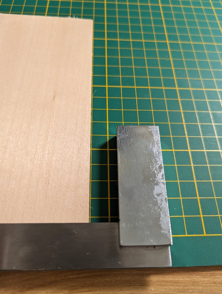
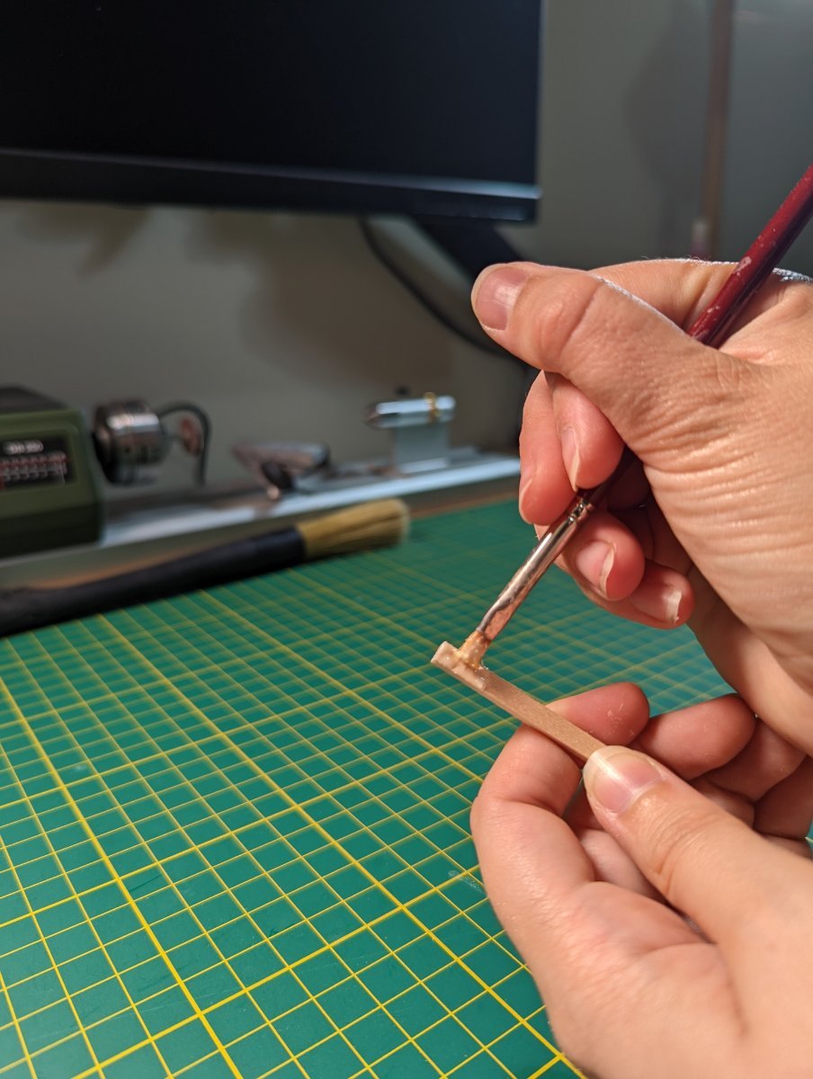
I filed down each step to show the curved front, and used a quick jig of square edges to keep the whole construction straight during dry install.
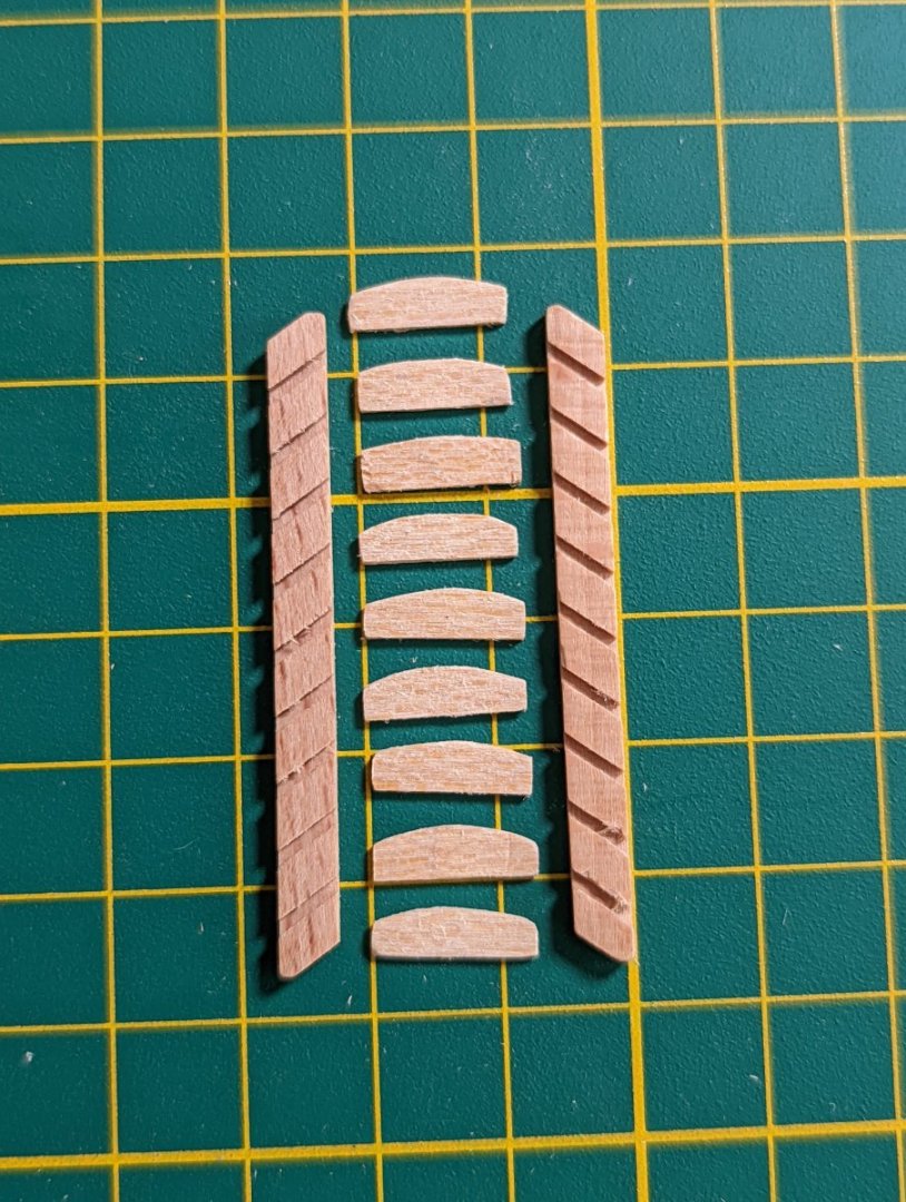

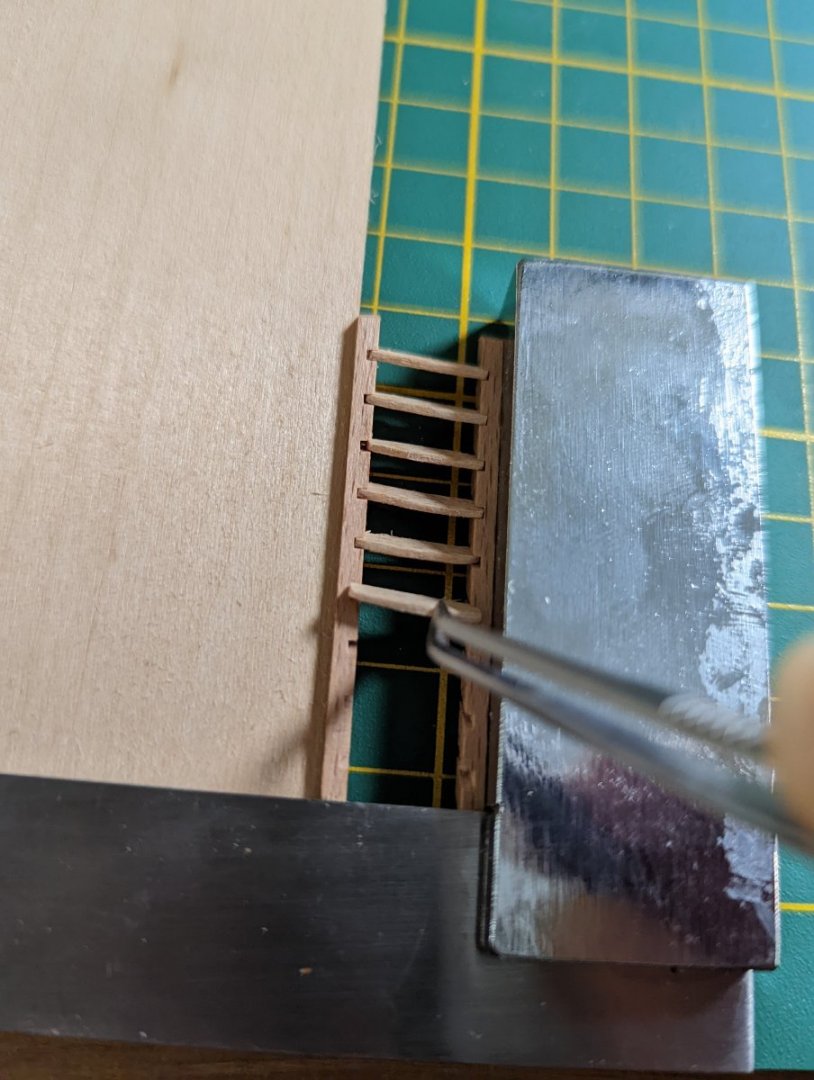

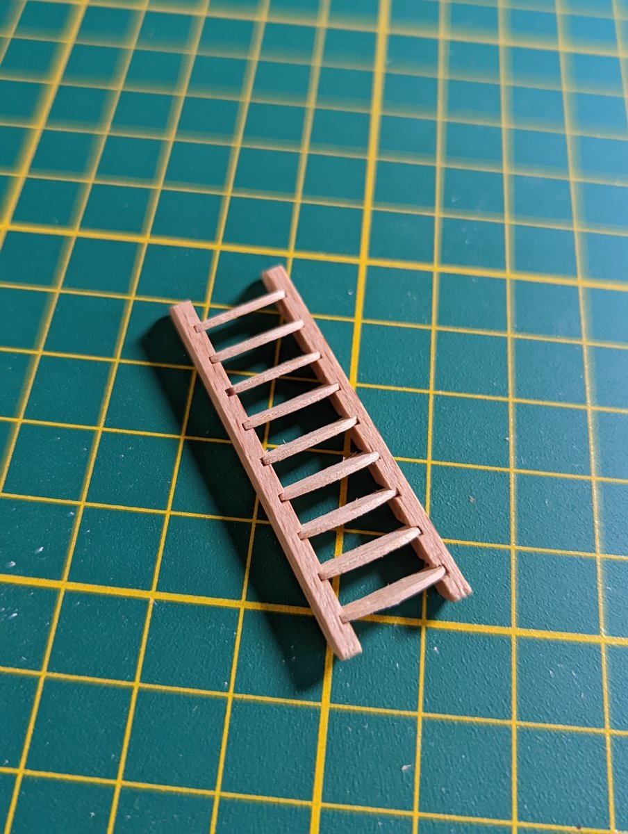
A brush of Titebond on each side and I left to dry.
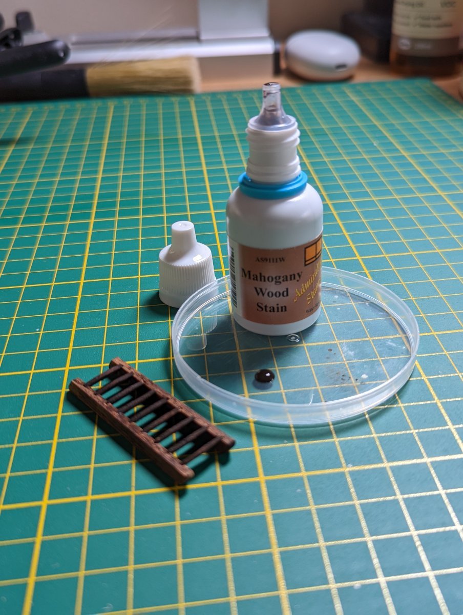
I used a mahogany wood stain from Admiralty paints to darken the wood. I'm going to be honest - the finish on this is not ideal, especially when compared to using real mahogony for the hatchways so recently.
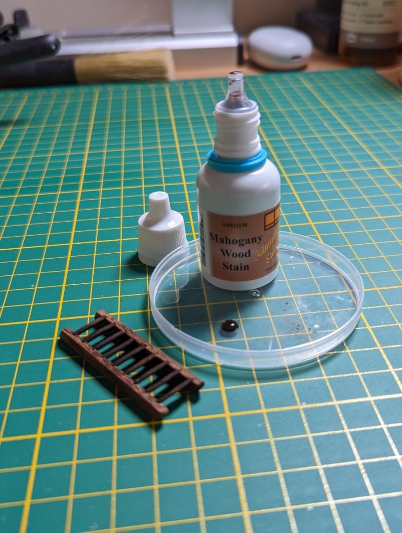

Given these stairs will be so imperceptible under the gratings of the forecastle hatchway, I'll leave this as is. However, for the stairs between the quarter and upper deck (much more visible), I'll swap out and scratch build using mahogony instead of the kit supplied wood and stain.
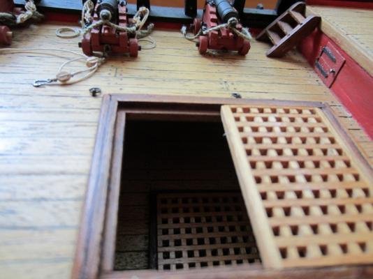
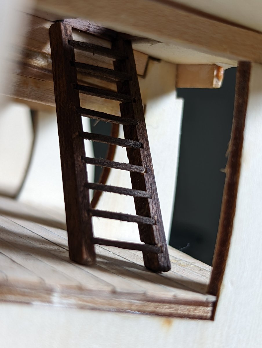
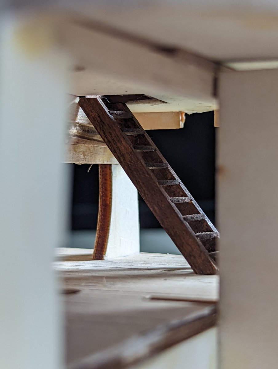
A few pics of the stairs installed.


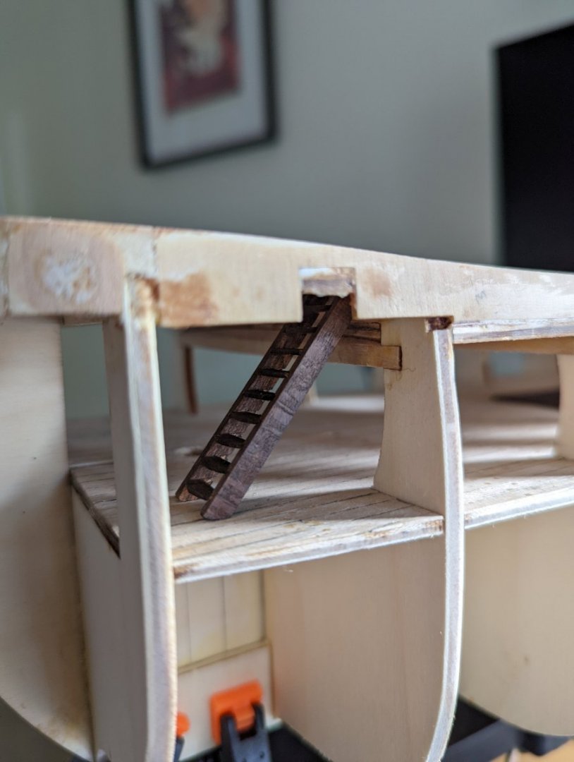
For all that and the below view (further eclipsed by a grating) is all we'll see of these stairs once the hull is closed.

Most importantly, I had a tonne of fun building these. This sort of miniature careful assembly is my favourite part of the build process. It makes me excited in the future (once I have more experience) to try building a ship that includes these neat internal hull details and furnishings.
Kristyn
- Gregory, Dave_E and GrandpaPhil
-
3
-
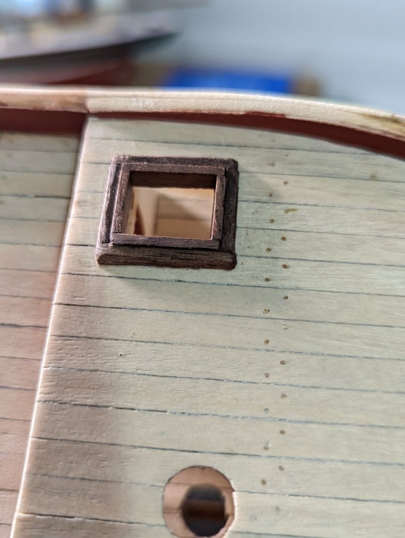
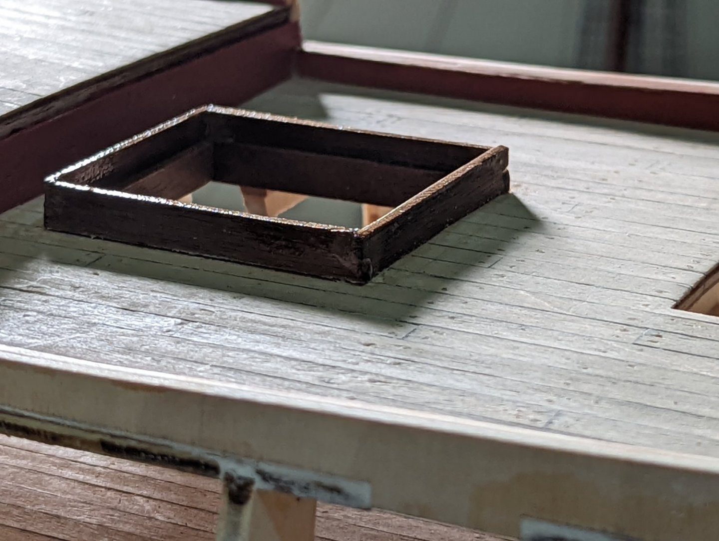
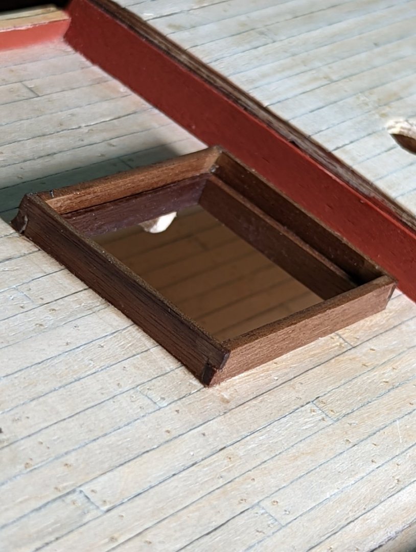
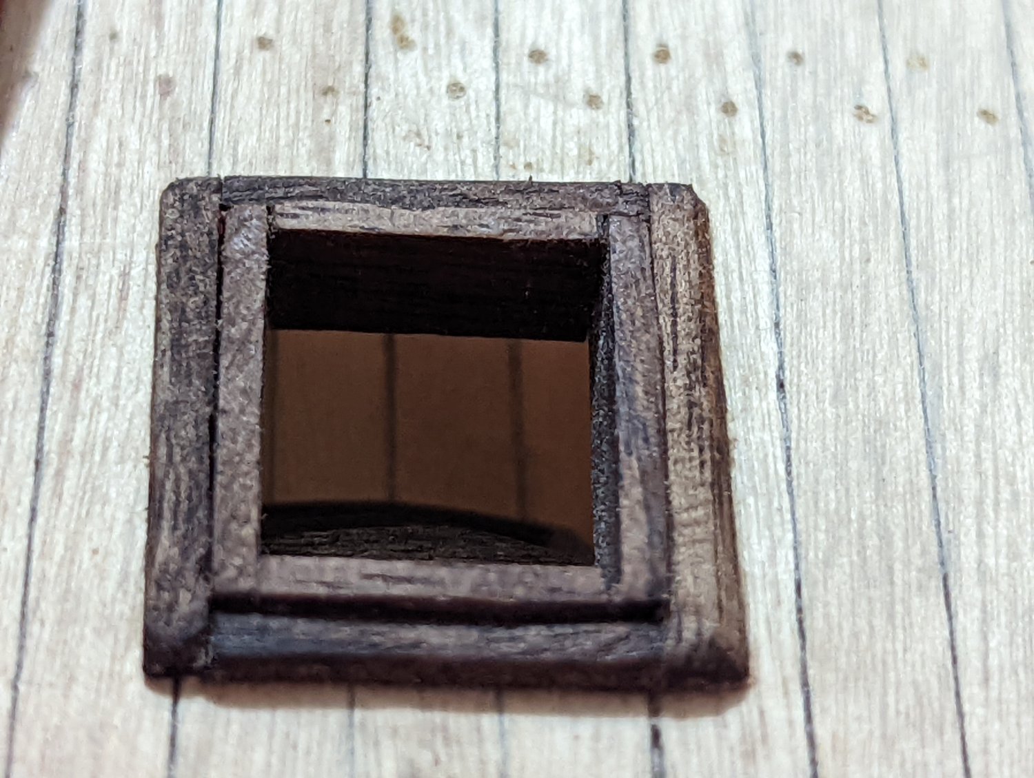
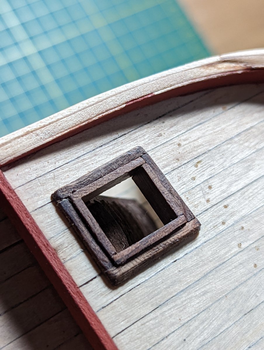
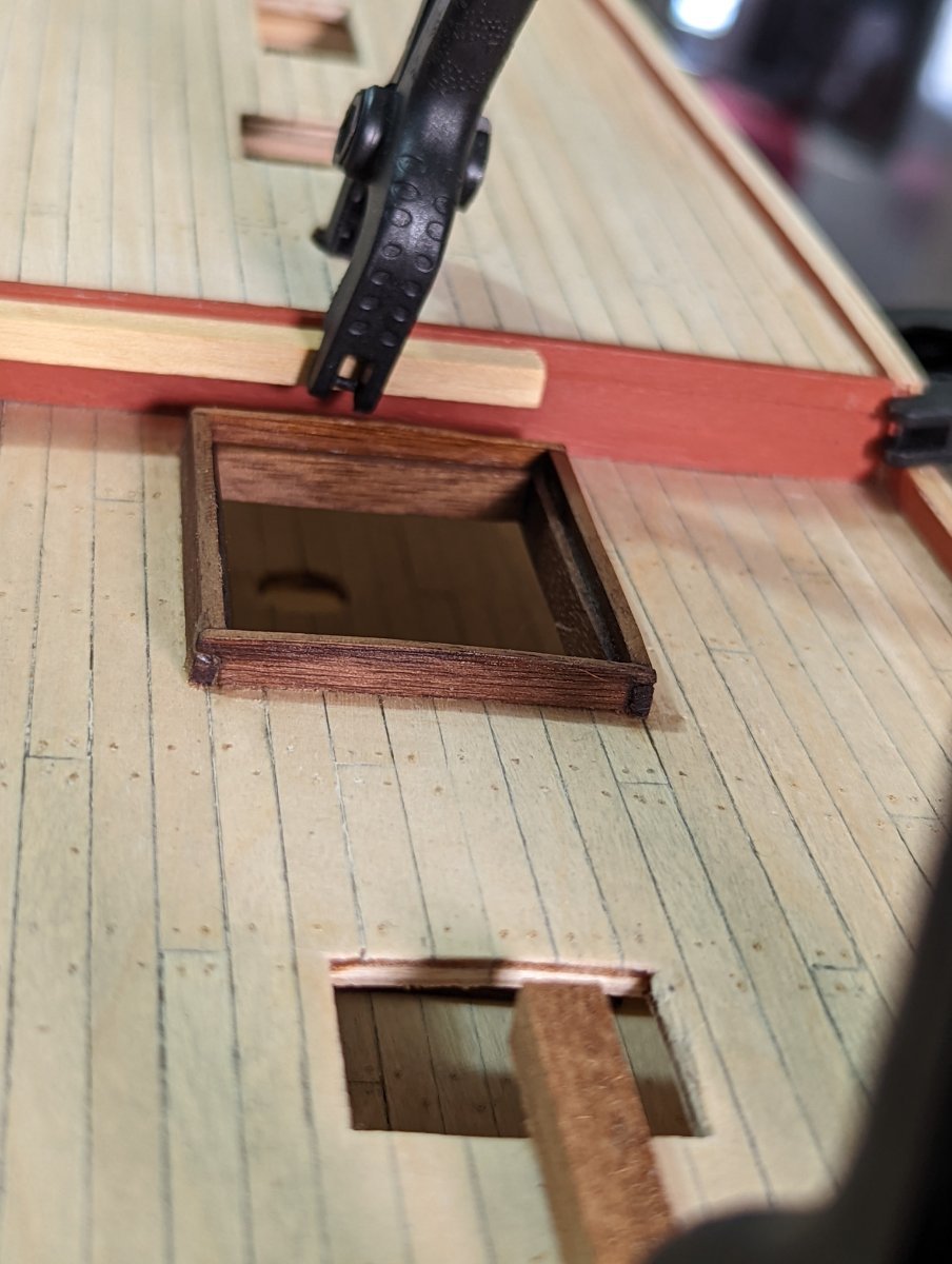
INSTALLING THE LOWER DECK MAIN HATCHWAY
Off the back of our discussions, this morning I fitted the hatchway on the lower deck. I measured this hatchway the same dimensions as the one on the upper deck, at 50x40mm.
Before fitting I checked out what these look like below decks in the Endeavour replica. I must be throwing the web stats for their virtual tour out of whack the number of times I've accessed this!
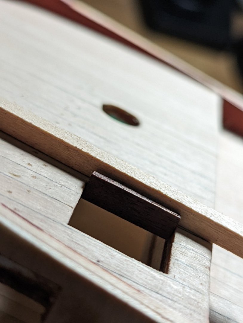
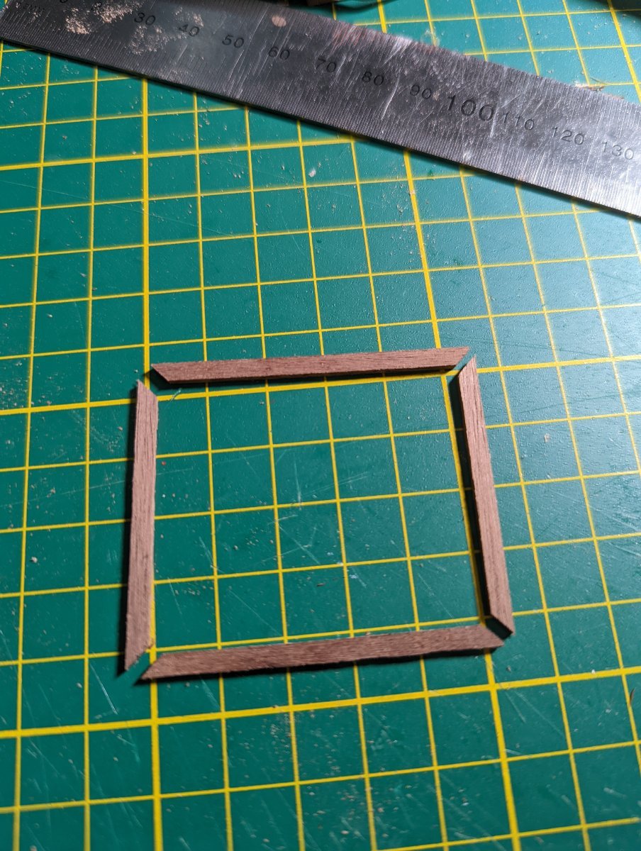
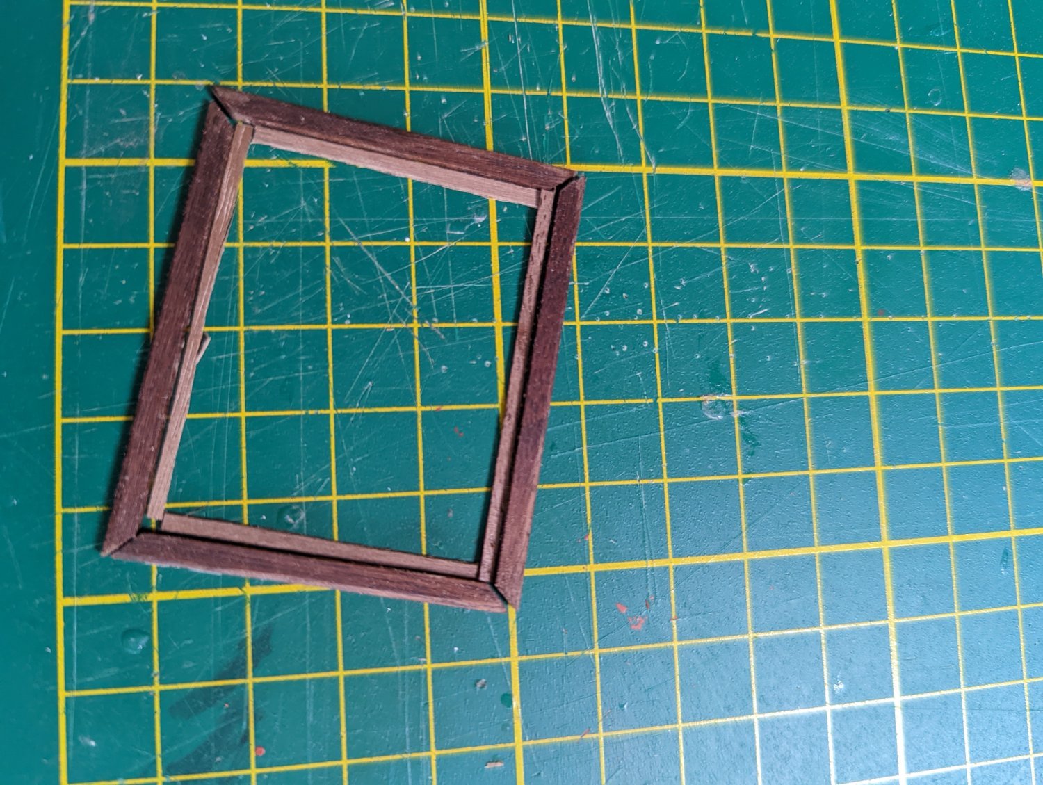
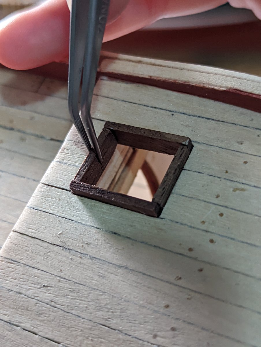
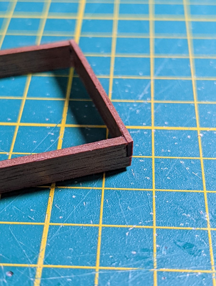
I kept this hatchway shallower than the one on the main deck, electing 45° mitre joints for the outer wall and a simple square butt for the inner.

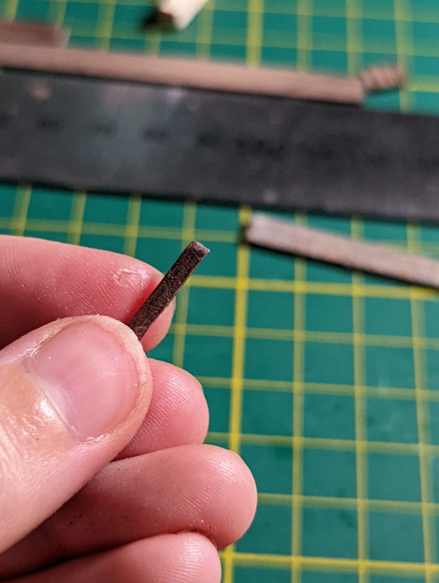
The inner wall I used 0.5mm scrap mahogony strips, which I then dipped in Tung oil (after this photo).
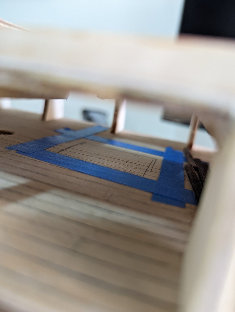
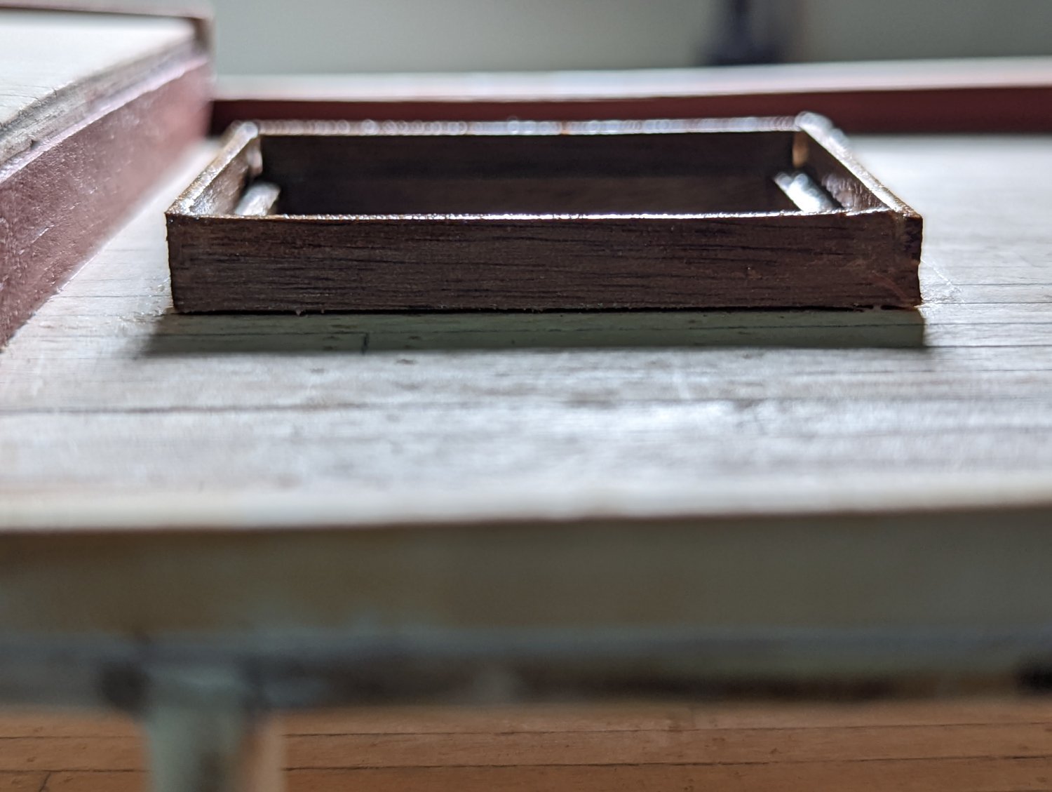
I measured the inner part of this hatchway and follow Steven's approach for a false hatchway, I masked it off and painted the inside black.
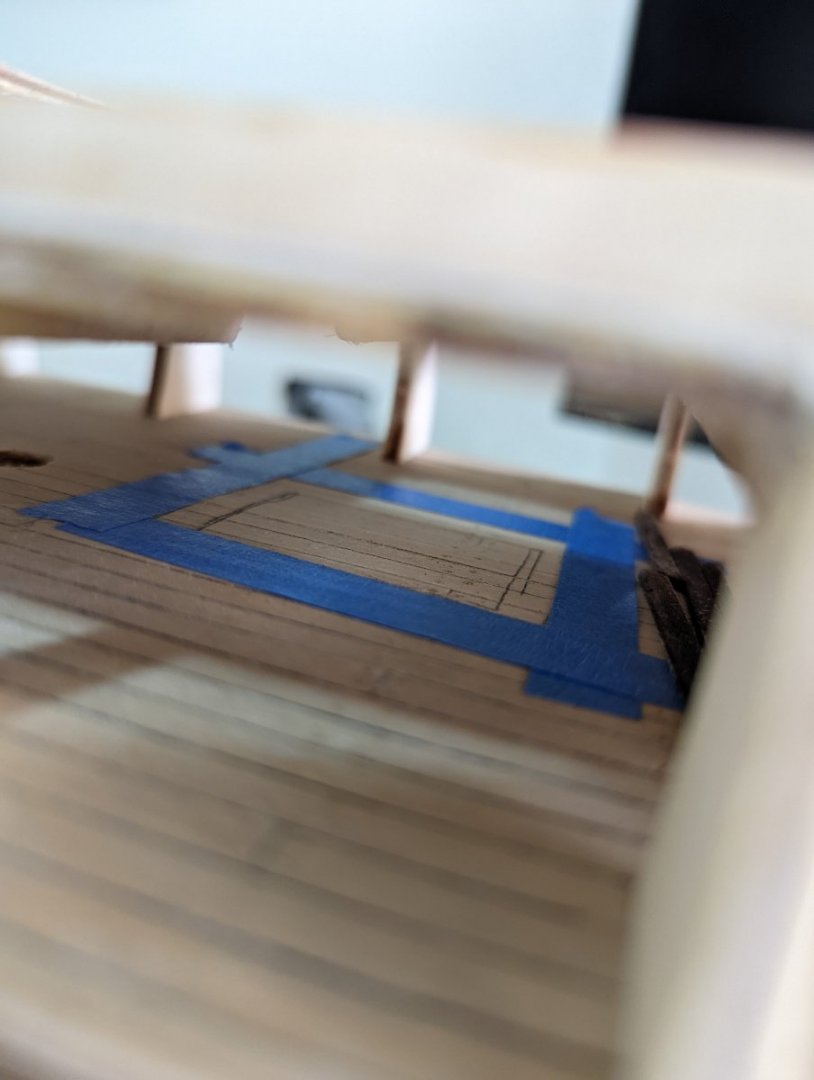

I clamped the outer wall down with some scrap wood so it would dry flat.

While waiting for it to dry I painted the caps on the forecastle and quarter deck walls following the Endeavour replica's scheme.
The cap for the quarter deck required some notches to be cut in each side so the beam could sit in place against the inner bulkwarks.
When I installed this beam, it made a satisfying "click" into place.
I then clamped everything judiciously, using thick scrap wood to push the beams snug against their respective deck.

- Prowler901, GrandpaPhil and Dave_E
-
3
-
Thanks, Steve! This collection is a very good selection of example hatch coverings.
Now excuse me as I shamelessly steal some of the photos from your build...
I like the main hatch in your Endeavour build, and now you mention it I think it's because it's not entirely closed. Not only does this add a bit of variety for the eye, but for me this means I'll be able to better show off those treenails I was so chuffed about on the lower deck and the lower hatchway.
When you installed the lower hatchway what did you do to the lower deck to prepare? In the OcCre kit, the lower deck sits directly on the bulkheads. Did you cut the bulkhead away where this lower hatchway sits? Or because it's so far down, I guess no one would be able to see through that second layer of gratings...
And yep, I get your point on the skylight. Quick peruse sees a lot of variation on the Endeavour models in MSW. By comparison your build and the replica (last two photos) show a grating style cover.

Kristyn
-
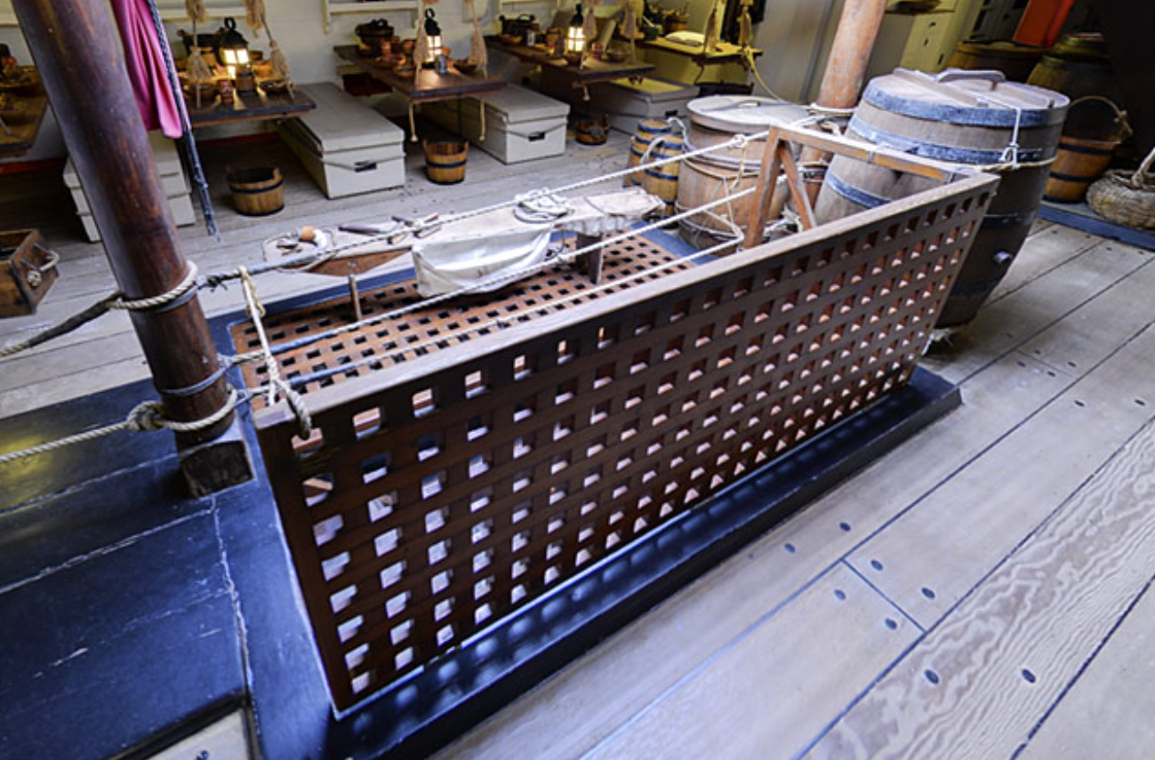
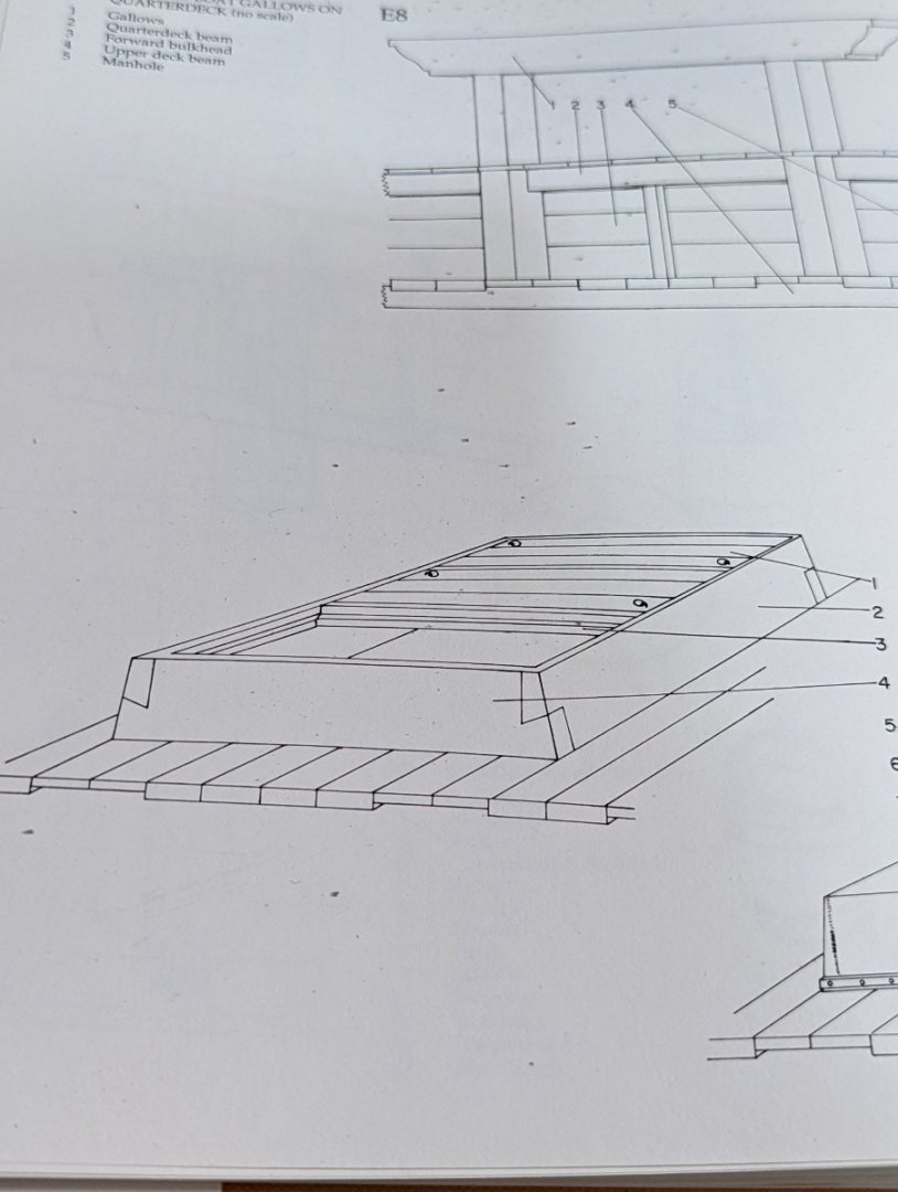
HATCH GRATINGS
As I mentioned at the start of this build, one of the reasons I am enamored with this hobby is not only the build but the research. I'm taking a moment to pause and check my assumptions on the hatchways.
The OcCre kit recommends that the hatchways are covered with hatch boards and rings... which is the same as recommended in Marquardt's book. I'm really hesitant on this because, to be honest, I find a lot of rings installed in this fashion seem oversized.
So I'm deviating for the main hatchway - instead opting for a hatch grating. I like visualising my Endeavour "smooth sailing" in the warm waters up and down the Eastern Australian coast, where it'd be warm and relaxed and hatchways would be open to the fresh air and sun.
The replica has gratings installed and so too do some of my inspiration builds on here (like Steve's Endeavour).
Anyway, this is a long winded way of saying I've ordered some 1.19mm cherry gratings (inc camber) from Syren. With the jig, I can push these gratings as wide as 2mm.
Some research and this seems reasonable scale wise for the 1:54 I'm working to.
So I'll be pausing on adding the covers until they arrive from overseas! So onwards in the meantime.
-
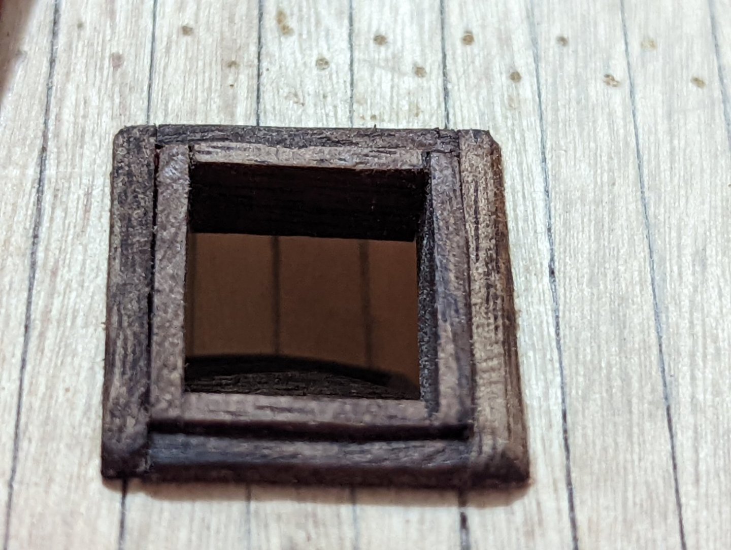
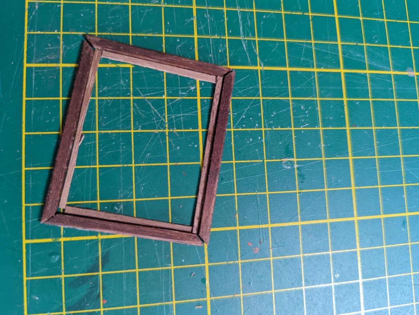
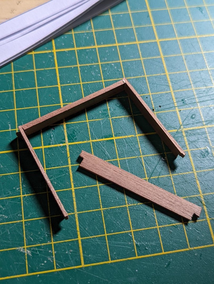
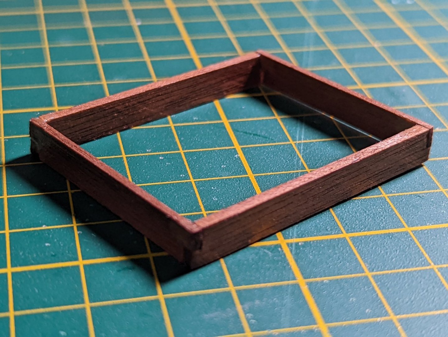
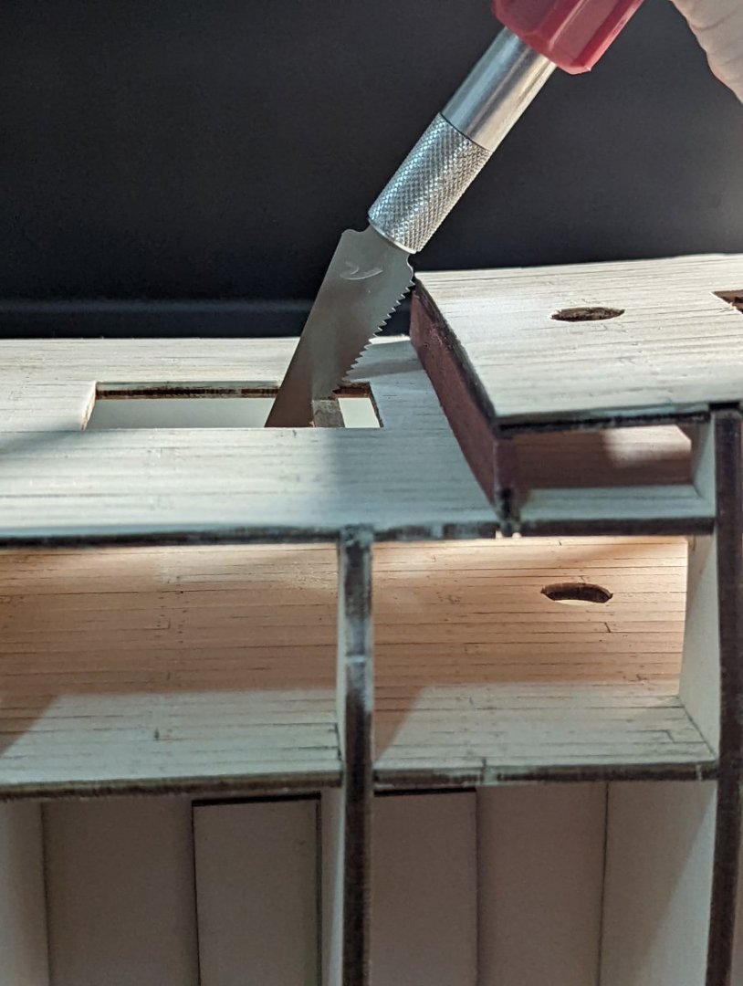
BUILDING HATCHWAYS
After finishing the inner bulwarks, I installed the helm port, main and forecastle hatchways.
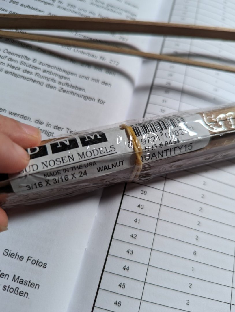
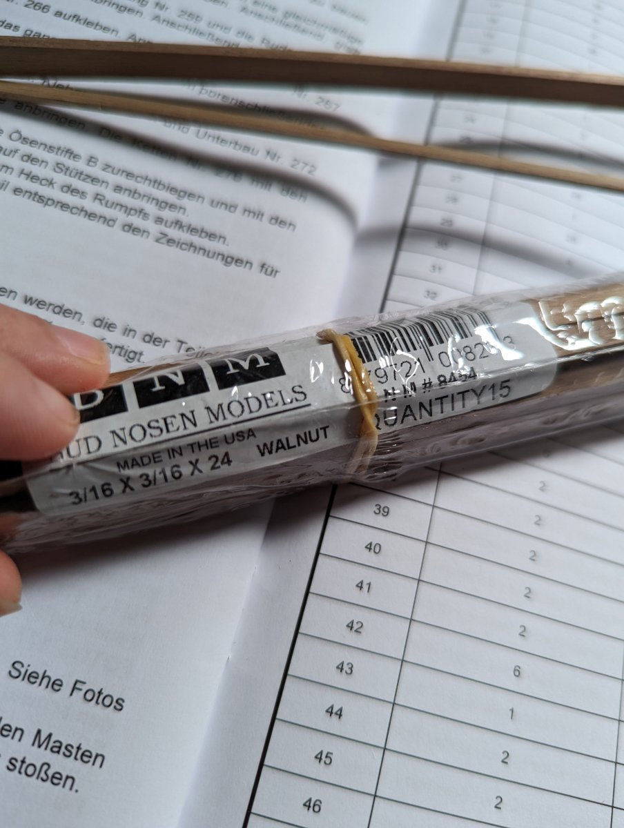
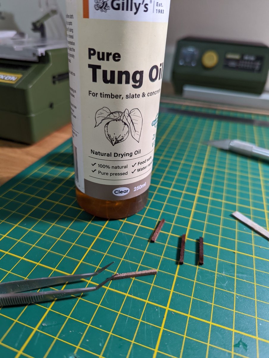
The OcCre kit provides limewood for these hatches that are painted with a walnut stain. I substituted the kit provided wood for walnut from Bus Nosen I have in my spares drawer.
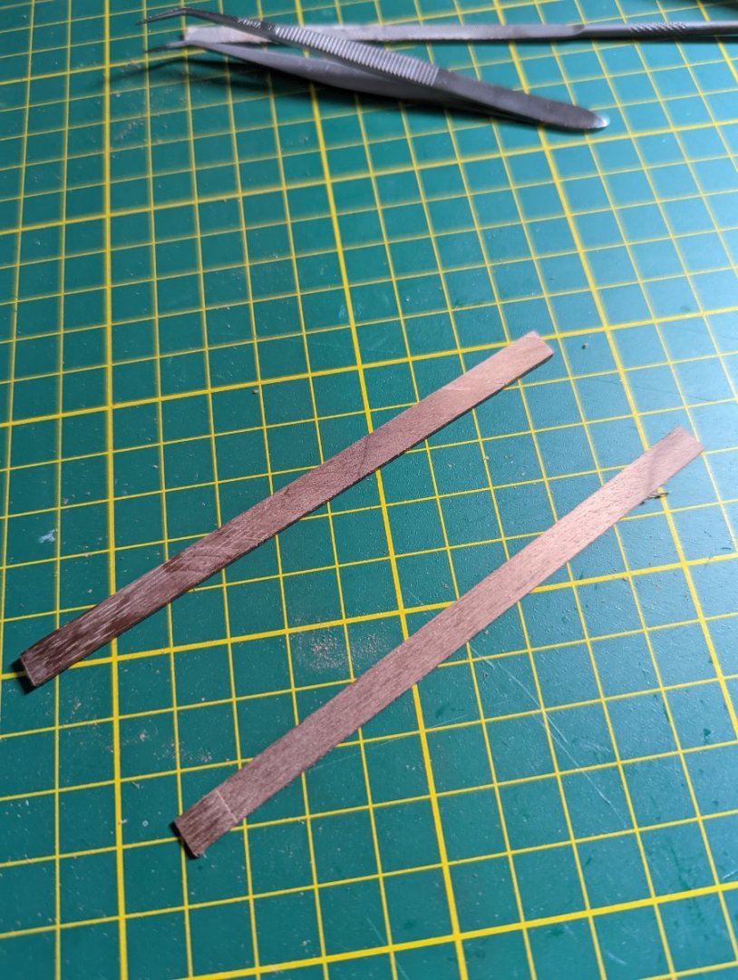
I had to mill down some of the strips to their relative sizes, giving the table saw a nice workout.
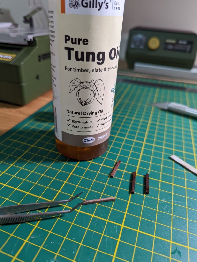
To make the walnut stand out, I dipped each piece in Tung oil before drying with a towel.
I elected for a basic butt (square) for the forecastle hatch and helmport, and bevelled the edges slightly.
When installing on the deck, I made sure to push each piece up against a scrap piece of squared wood.

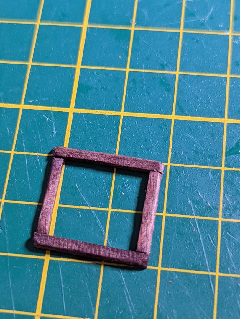
I opted for a half lap joint (I think?) for the main hatchway.
I did this because I found the kit instructions for the main hatchways deviated from Marquardt's rendition. Marquardt's shows a single, slightly tapered hatch with no bevelling - I opted to follow his interpretation.
I put the main hatchway together on my cutting mat before installing it on the deck.

I'm planning to file it down so it's not as high and follows the slight camber of the deck. I need to wait for tomorrow to do this so the glue had the opportunity to cure.

Next time I'll install some more walnut and think on the main hatchway gratings or covers.
Kristyn
- Dave_E, Prowler901, Gregory and 2 others
-
5
-
Thanks, Steve -
I have some push pins I've acquired from a hobby store I intend to use once I get to planking the hull.
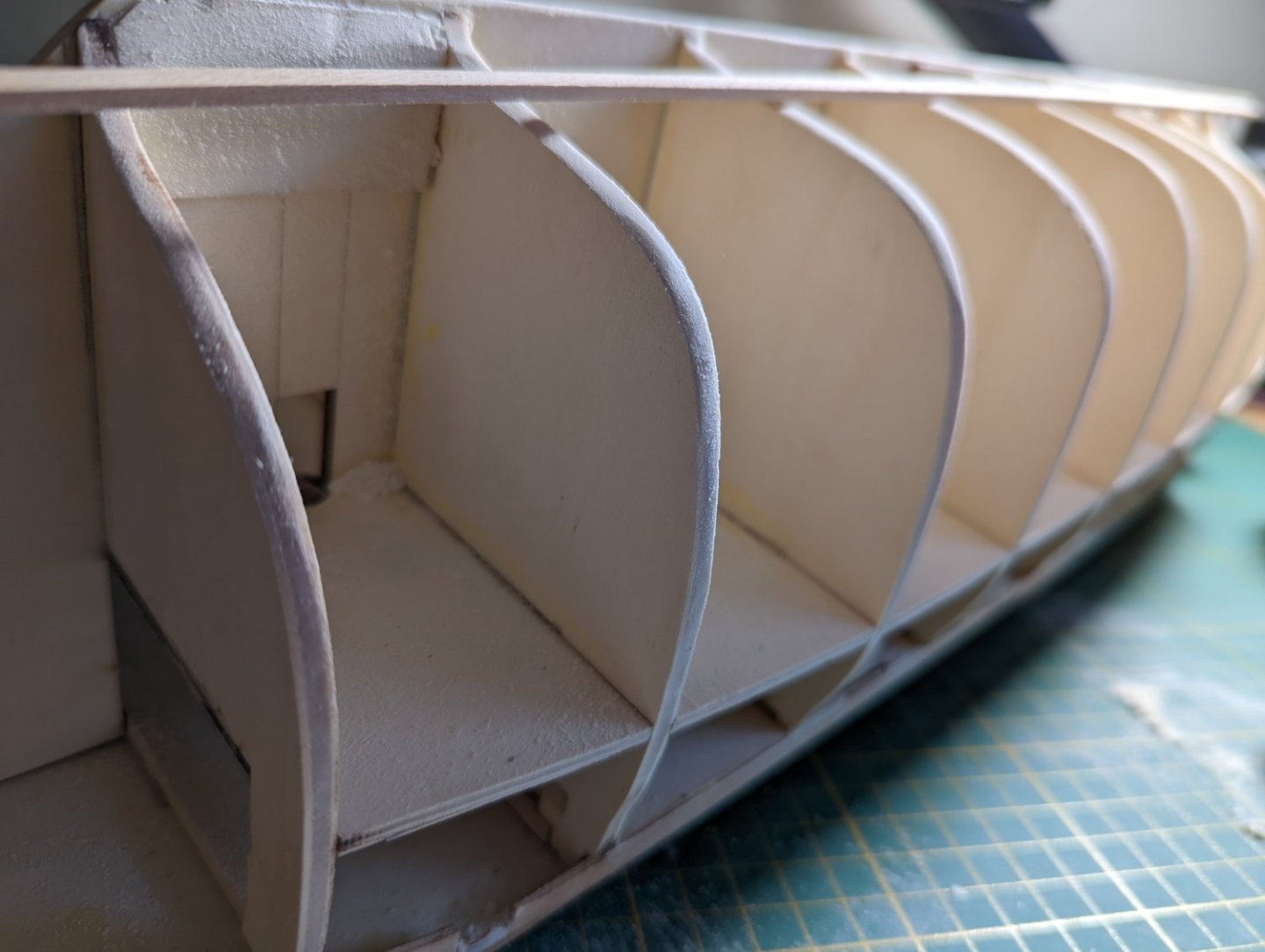
FINISHING THE INNER BULWARKS
Today I finished cladding the inner bulwarks, first a 2mm thick cladding, and finally a red painted 0.6mm cladding.
The bow inner bulwark 2mm cladding needed bending, and the whole exercise took time and patient clamping.
I soaked the 2mm thick cladding and intended to use my plank bender to let them dry in shape... But the bender was a little small and I found it just as effective to clamp them wet in place against the bow curve to dry. This method ensured the curve was exact.
Once dried, I then glued into place. I've read glueing down a wet plank can lead to gaps (noting that wet wood is expanded and shrinks back when dry), so didn't glue in place until the plank was bone dry.
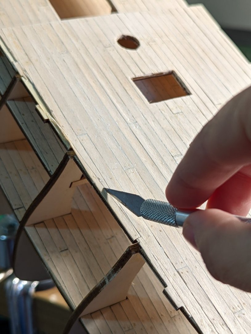
At each stage of cladding, I scored along the top of the bulwark with a scalpel to take the top off, then filed and sanded the top down to be even.


Once the first cladding was completed, I painted and clad the thinner 0.6mm wood, following the same process.
The final result:

I can see planking the hull coming up soon! Very excited to be reaching this stage!
- Dave_E, Seventynet and Gregory
-
3
-
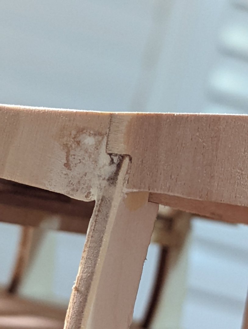
FITTING THE OUTER BULWARKS
I've spent the last few days slowly fitting the outer bulwarks of the Endeavour. This was a job of patience as I left each section to dry for a day at a time before sanding down.
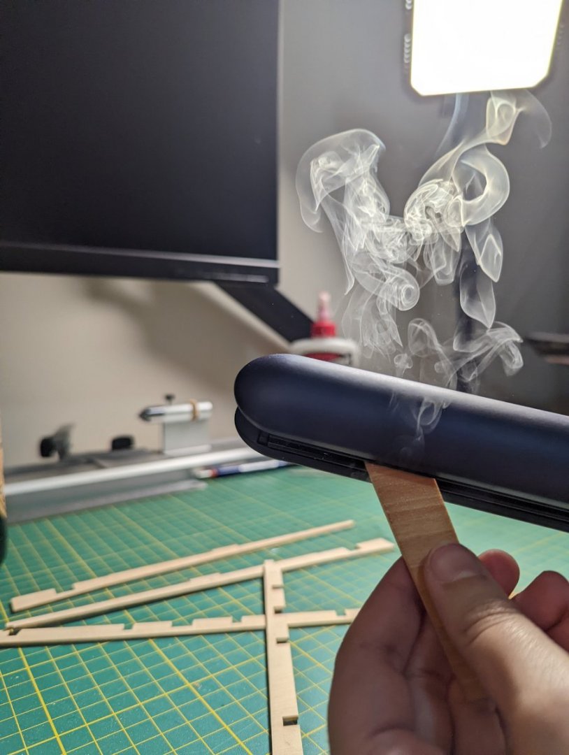
The bulwarks that wrapped around the bow needed to be bent. I've tried a lot of methods, but have found some good success using a hair straightner. All I need to do is soak the wood for about an half hour before drying the pieces and bending them between the tongs.
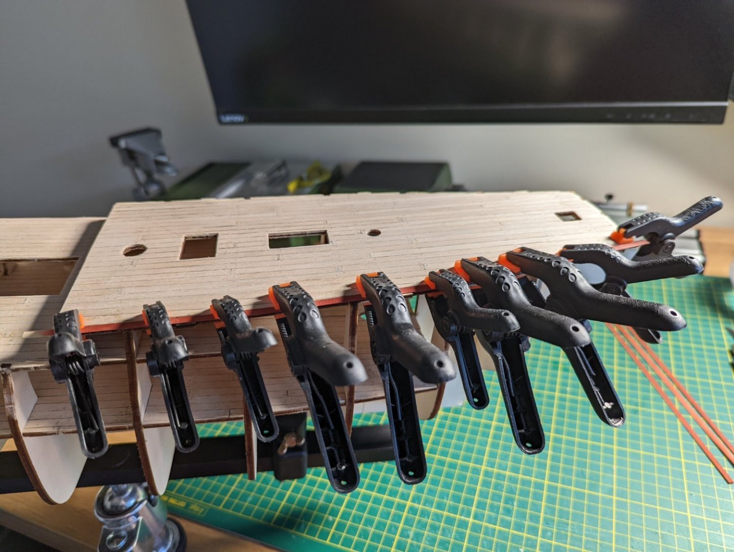
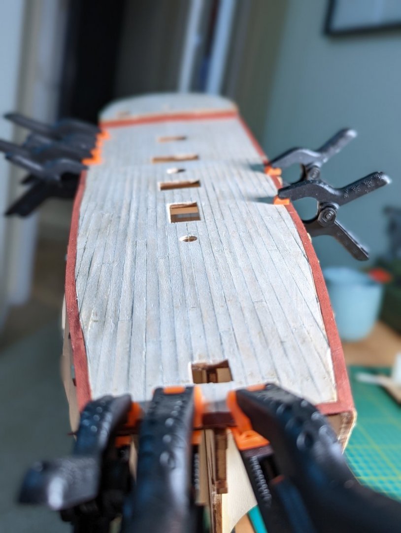
I used a lot of clamps and elastic bands to ensure as tight a fit to the decks and bulkhead tops as possible.

I found the fit between the bow bulwarks and the upper deck bulwarks as quite loose, so I applied a mix between sawdust and Titebond and Model Lite filler to smooth over these gaps.
Before sanding the joins:

After sanding the joins:

The visible filler is no issue as the bulwarks will be planked over and painted, the most important thing is that they're smooth as a baby's behind.
I took the opportunity while sanding down the filler to remove the laser cut charcoal edge on the frame. These will of course be sanded significantly more when fairing the hull prior to planking.


Next is onto cladding the inside of the bulwarks!
Kristyn ⛵
- Gregory, Seventynet and Dave_E
-
3
-
Ah, thank you so much Gregory!
I'm still stumbling over the terminology and appreciate the clarification. It can be hard to look up terms when you're not sure what you're looking for.
Your description is really helpful and I'll commit it to memory ☺️
On the topic of terminology ... You wouldn't happen to know what the "wall" demarcating between the upper deck and either the forecastle or quarter deck is called? On the Endeavour the wall is just aft of the main hatch.
Kristyn
-
-
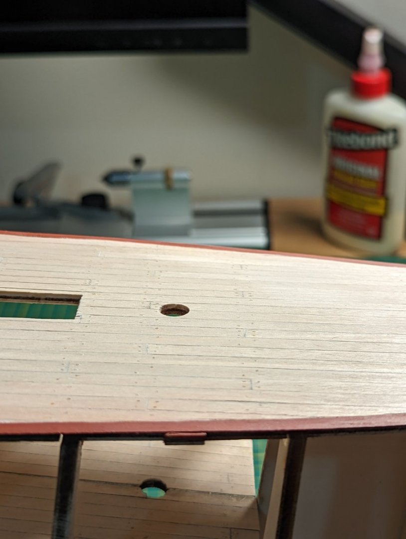
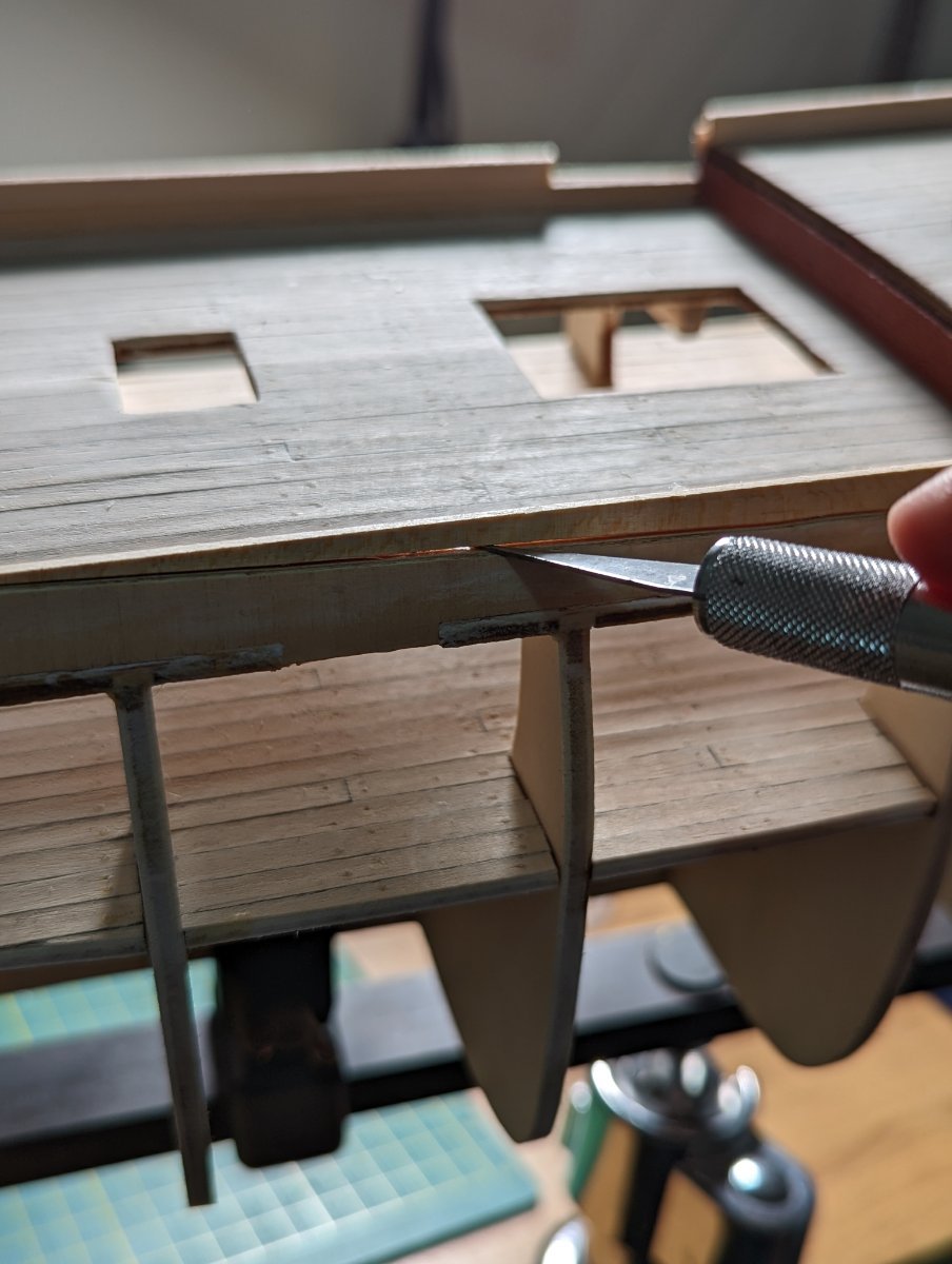
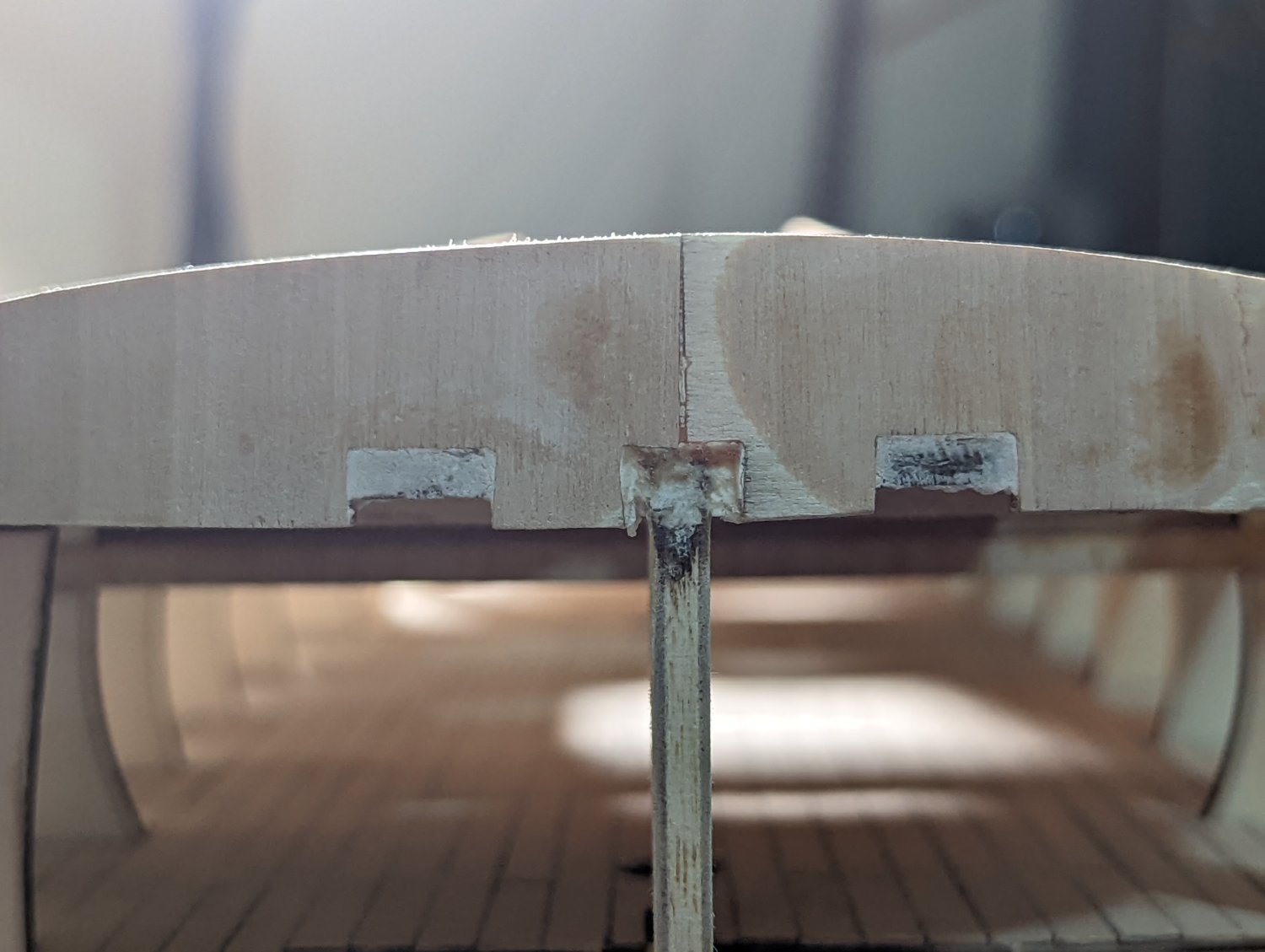
ADDING WATERWAYS
Before adding the waterways, I added the stern supports following the instructions.

I measured the waterways at 3mm, to accommodate the 2mm bulwark cladding down the line.
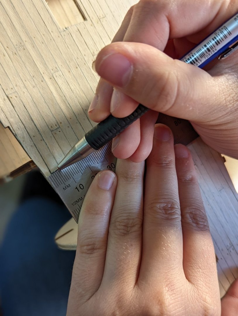
To do so, I used a pacer (sharper line than a pencil!) and my flexible ruler to carefully mark and then cut along the outermost edge of all decks with my no. 10 blade.
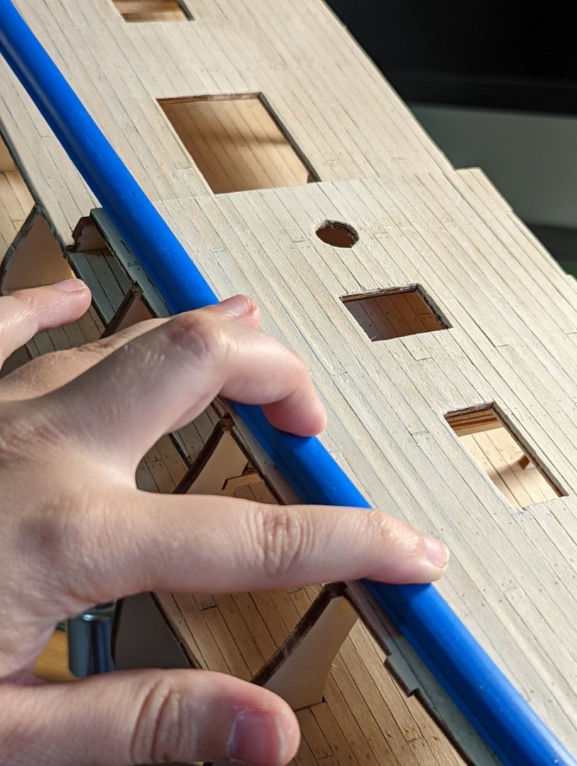
I used some leftover 0.6mm cladding I had from my Bluenose build for the waterways. They have a more pronounced grain than the OcCre kit (and will need to be judiciously sanded).
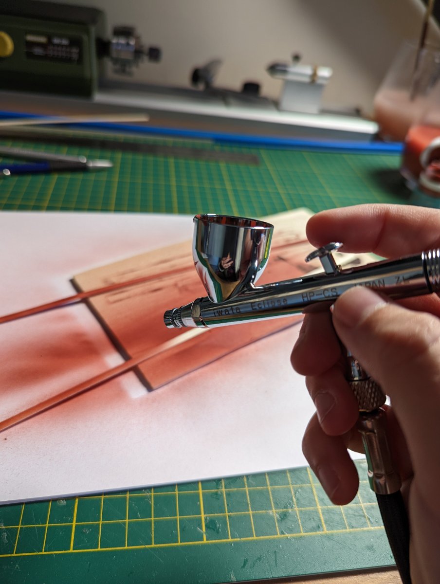
I gave my airbrush a whirl with the planks - I haven't airbrushed in nearly a decade, and then that was for larger areas (bicycle, motorbike). It'll take me a little bit to remember.

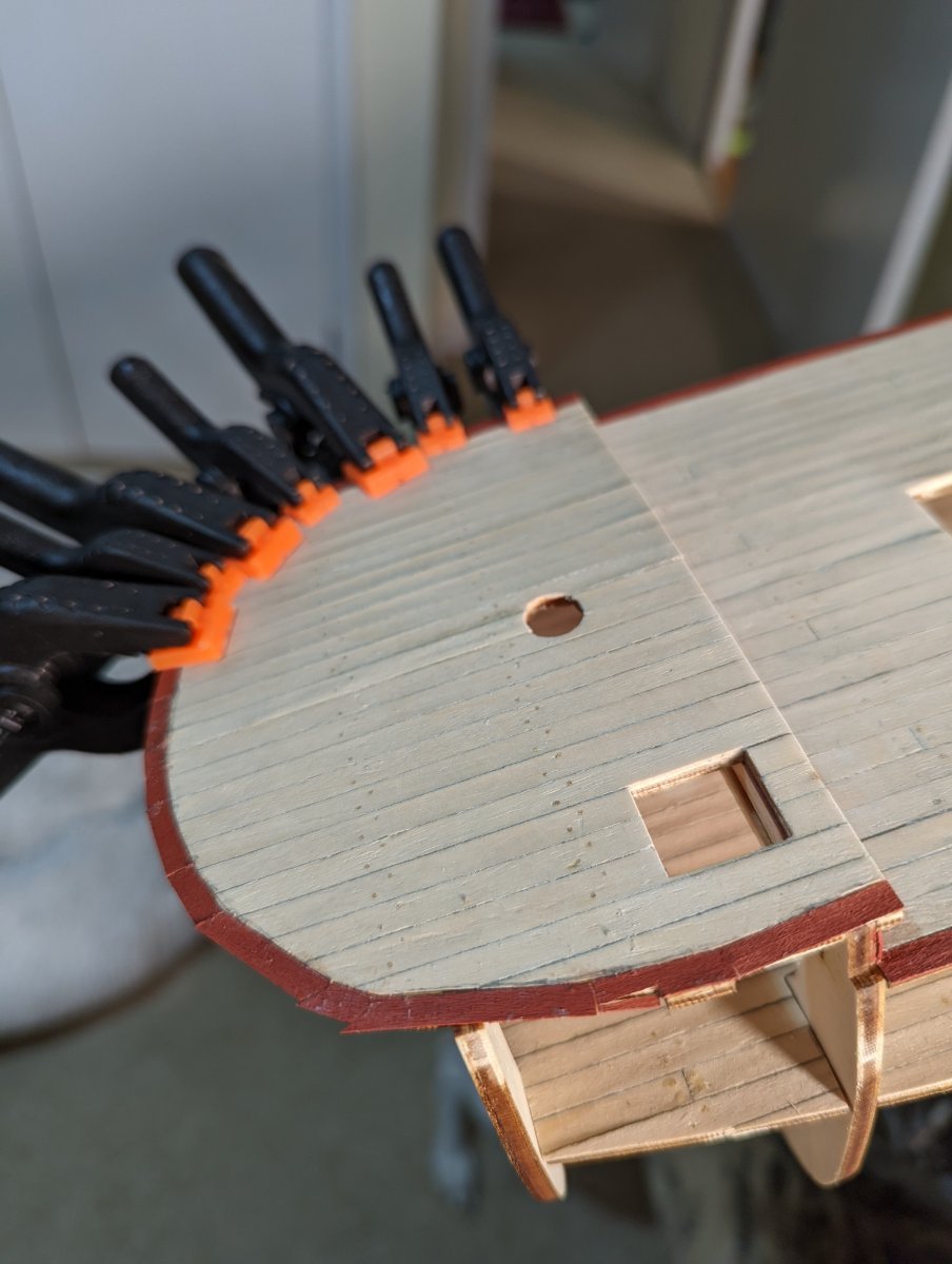
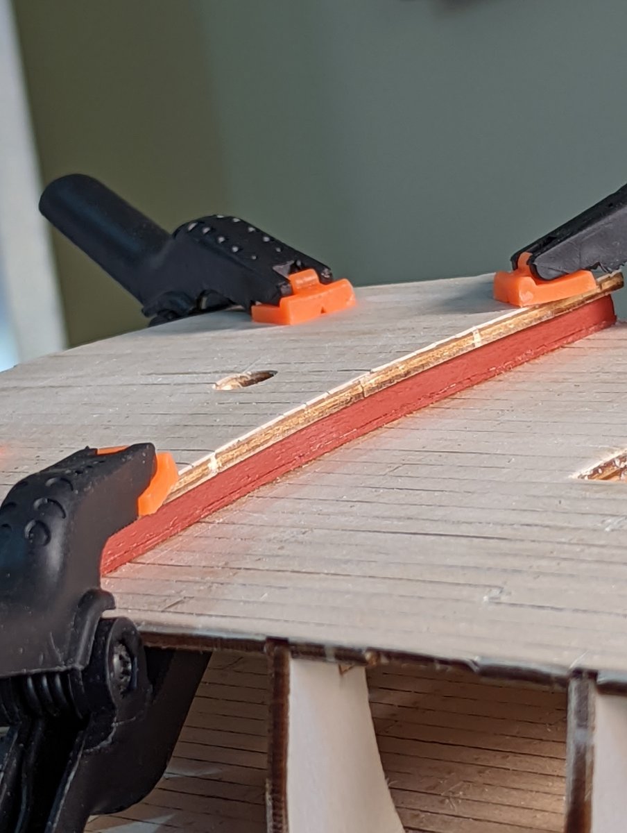
Clamping the waterways on the quarter and upper decks were easy enough as they had very slight curved that could be maintained with slow clamping. The forecastle deck was much trickier.
At first I tried bending the wet plank to shape, but as I'm attempting to bend very thin (0.6mm) wood lengthways, it goes against what the wood wanted to do.
I gave up bending and instead elected to cut small segments against the curve of the bow.

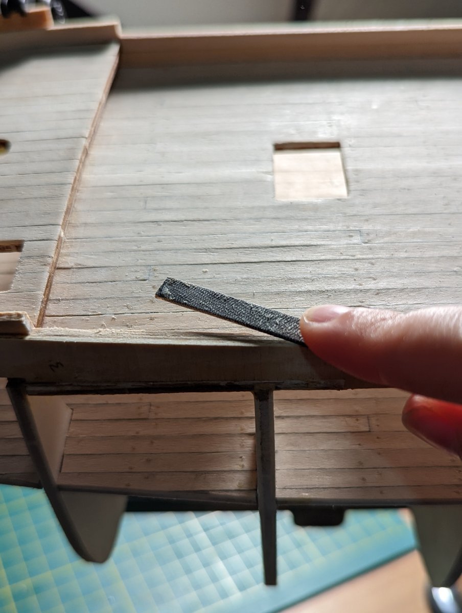
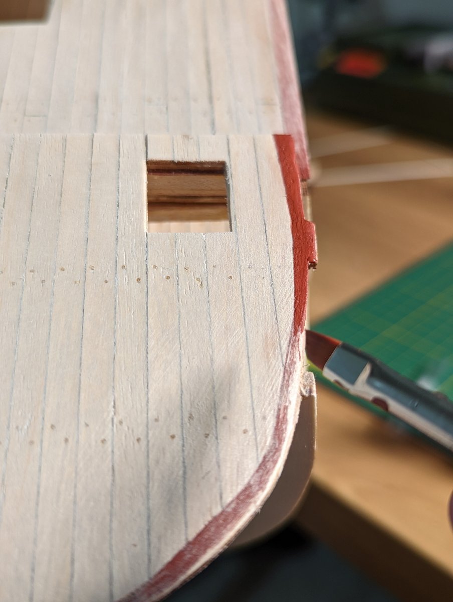
I then sanded the waterway down to help mask the joins. While I was at it, I decided to sand and fill the small gaps between planking and waterway.
Rex my dog was very interested.
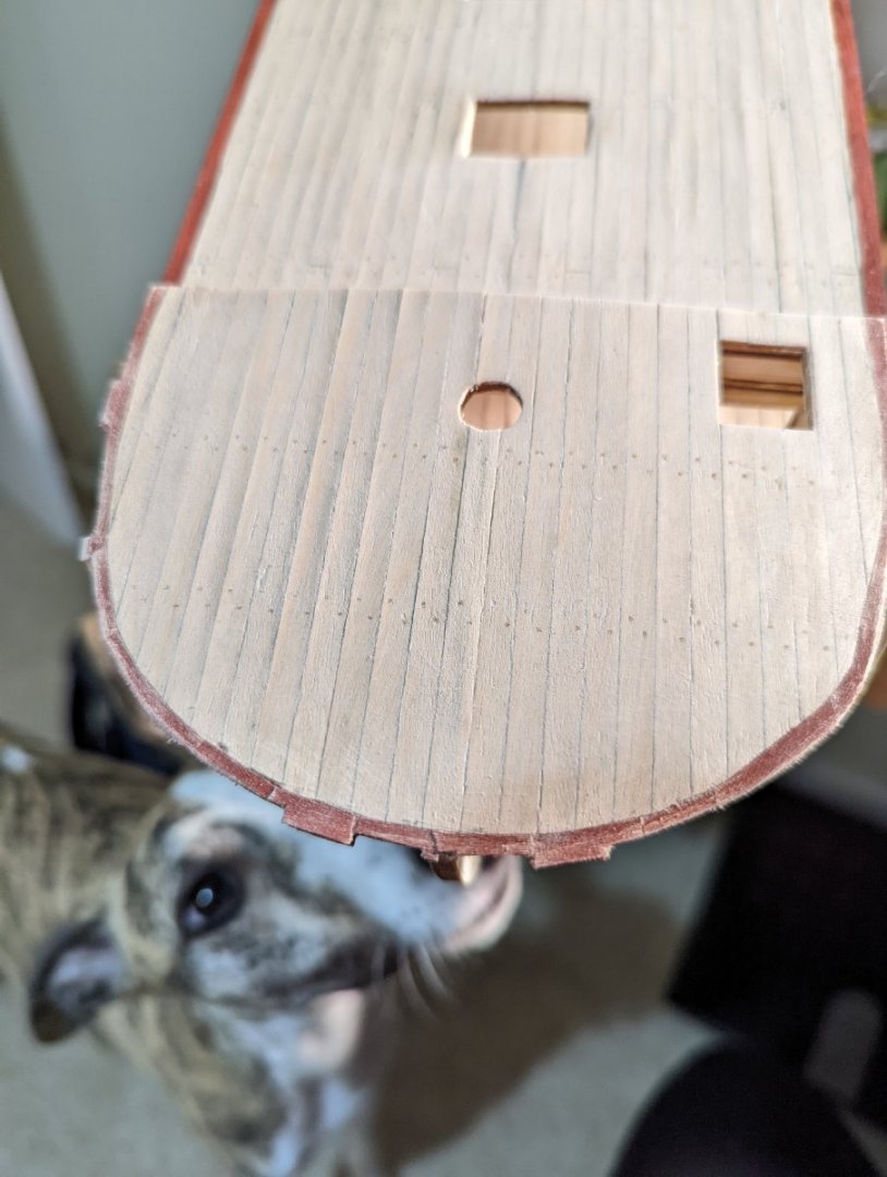
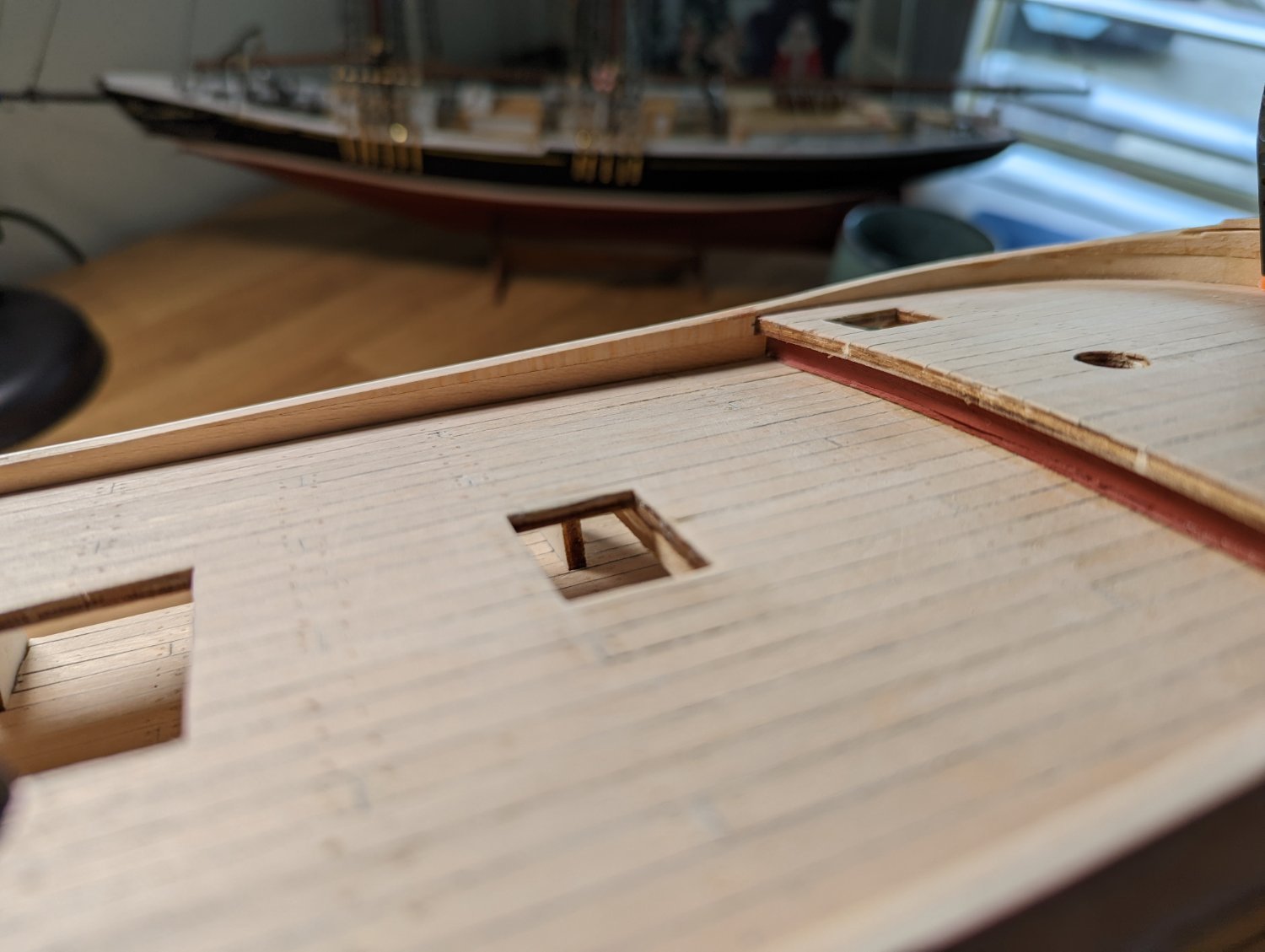
I then repainted (!) carefully. The end result are waterways that are much smoother and better finished flush against the planking of the deck.

And in closing, my dog wanted attention - say hello to Rex, the good boy!

Kristyn ⚓
- Dave_E, Seventynet, Dray and 1 other
-
4
-
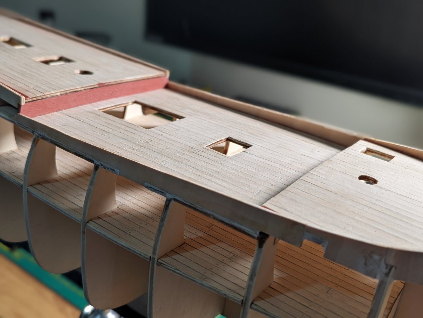
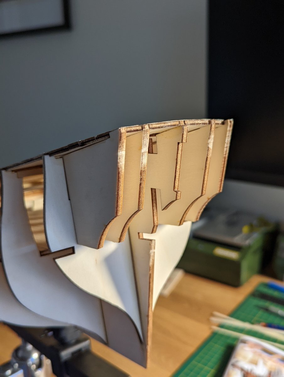
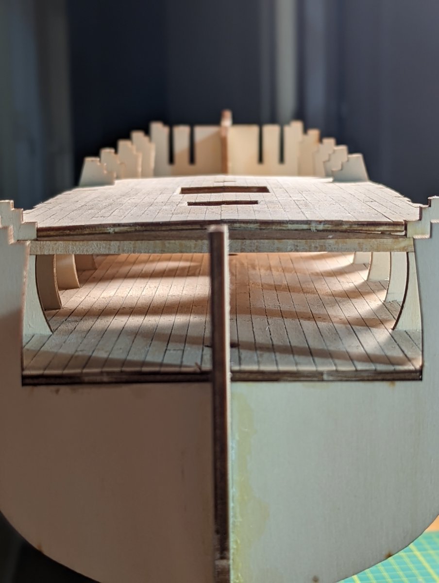
FITTING THE FORECASTLE DECK
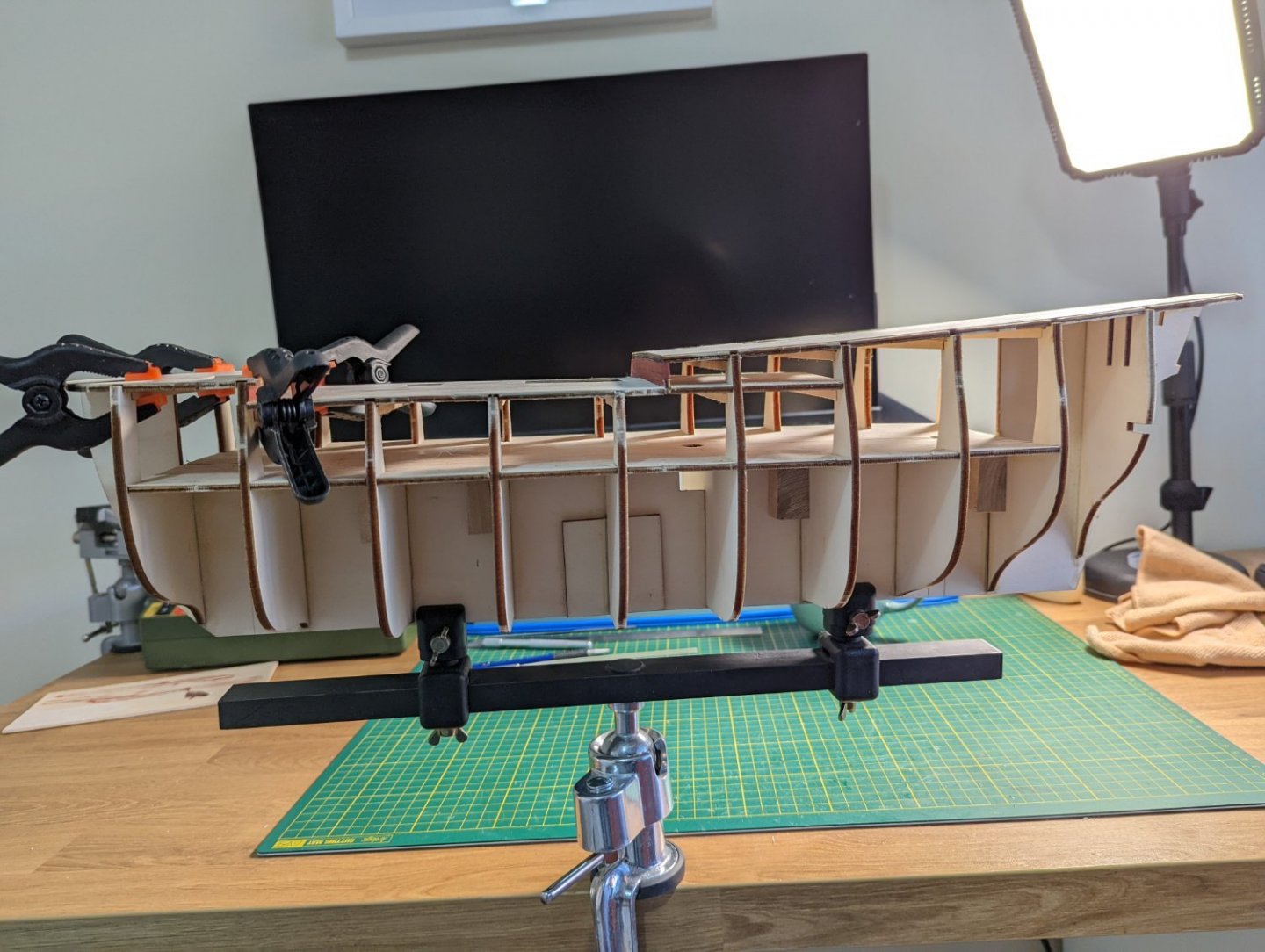
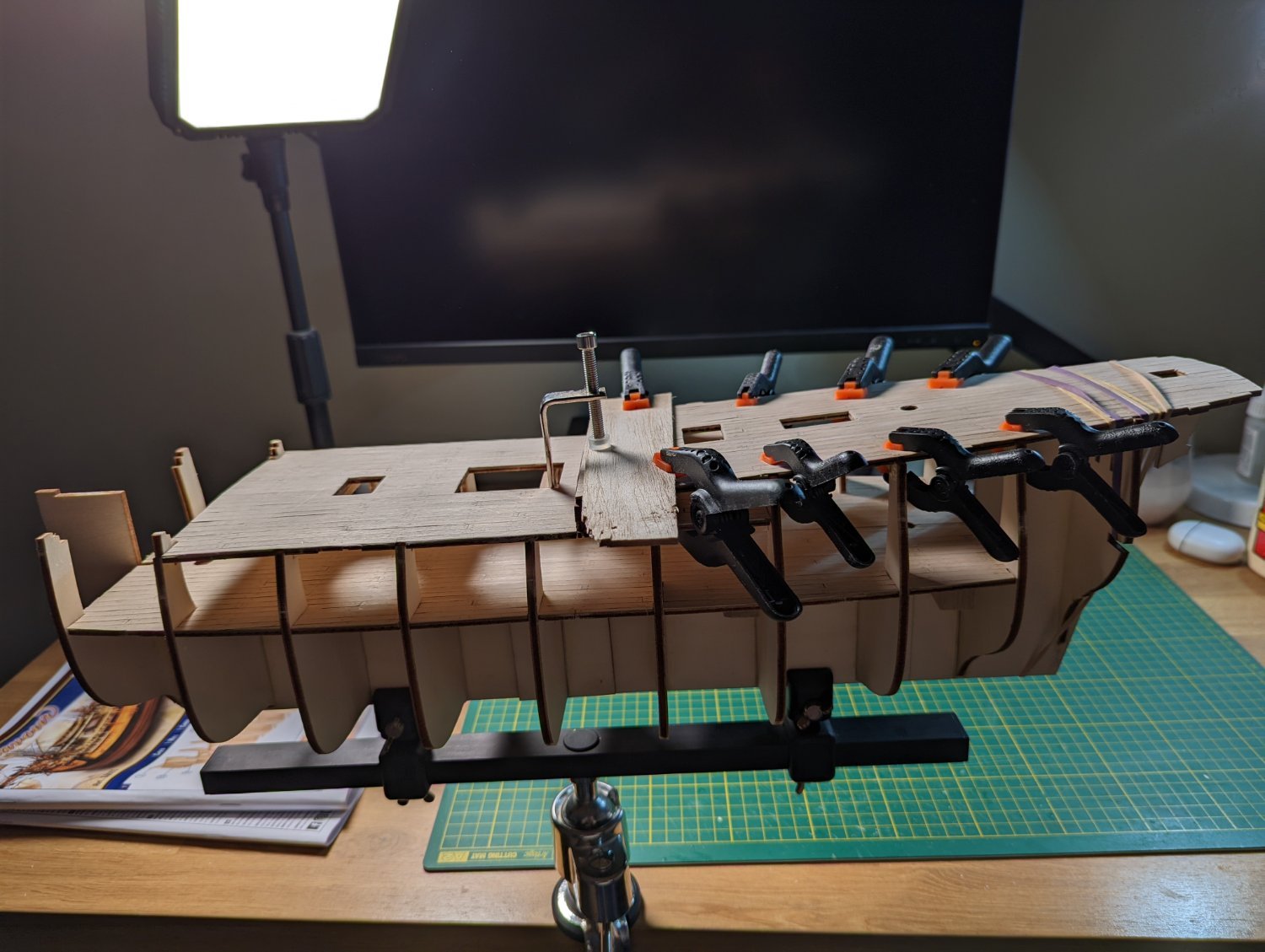
I spent a couple of days laying the beams and setting the forecastle deck.
Before doing this, to shipaholic's suggestion I removed the beam that was interfering with the main hatch.
My table saw arrived, so I was able to cut the beams to support the deck to a level of accuracy that had previously been beyond me.
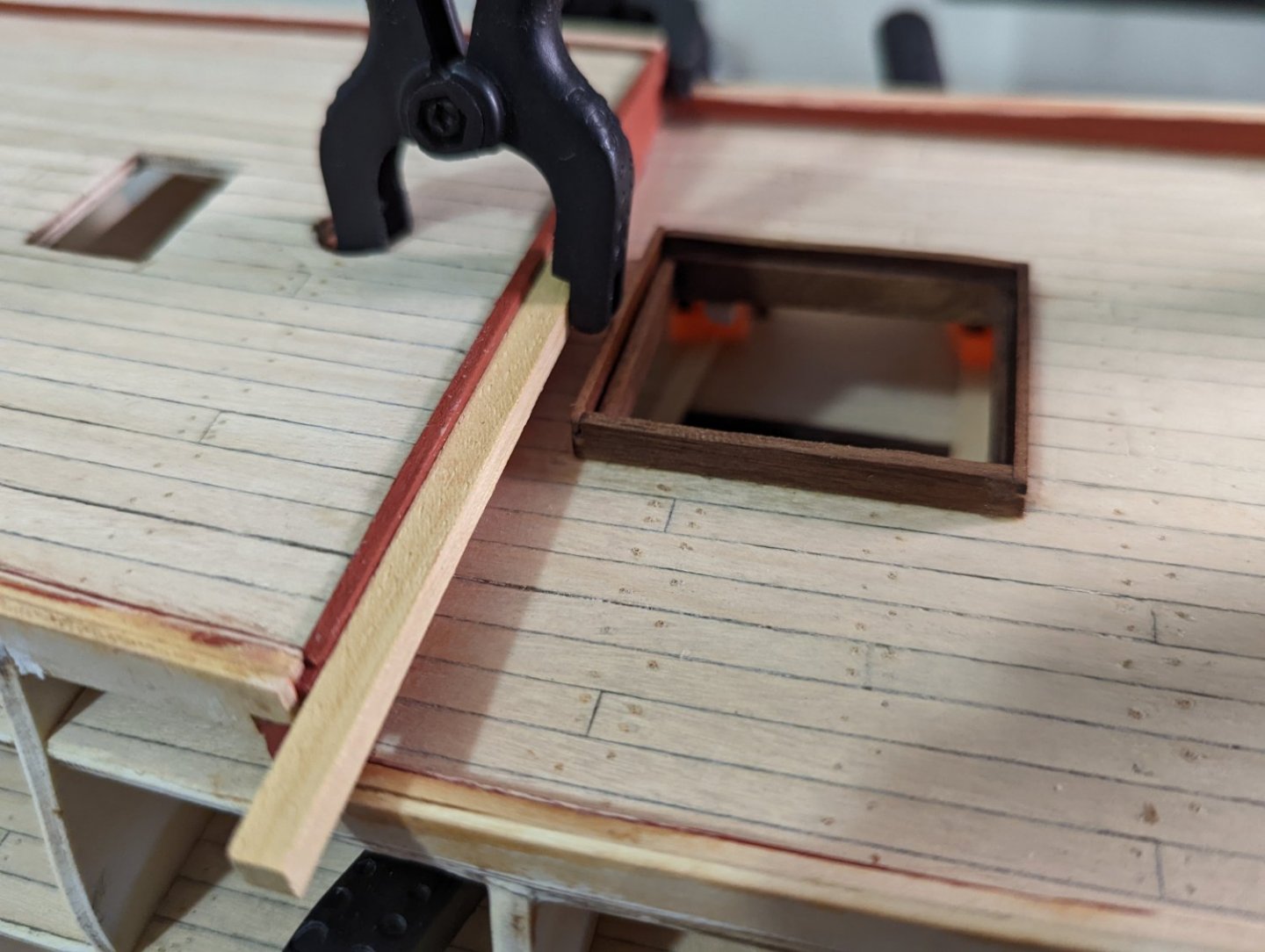
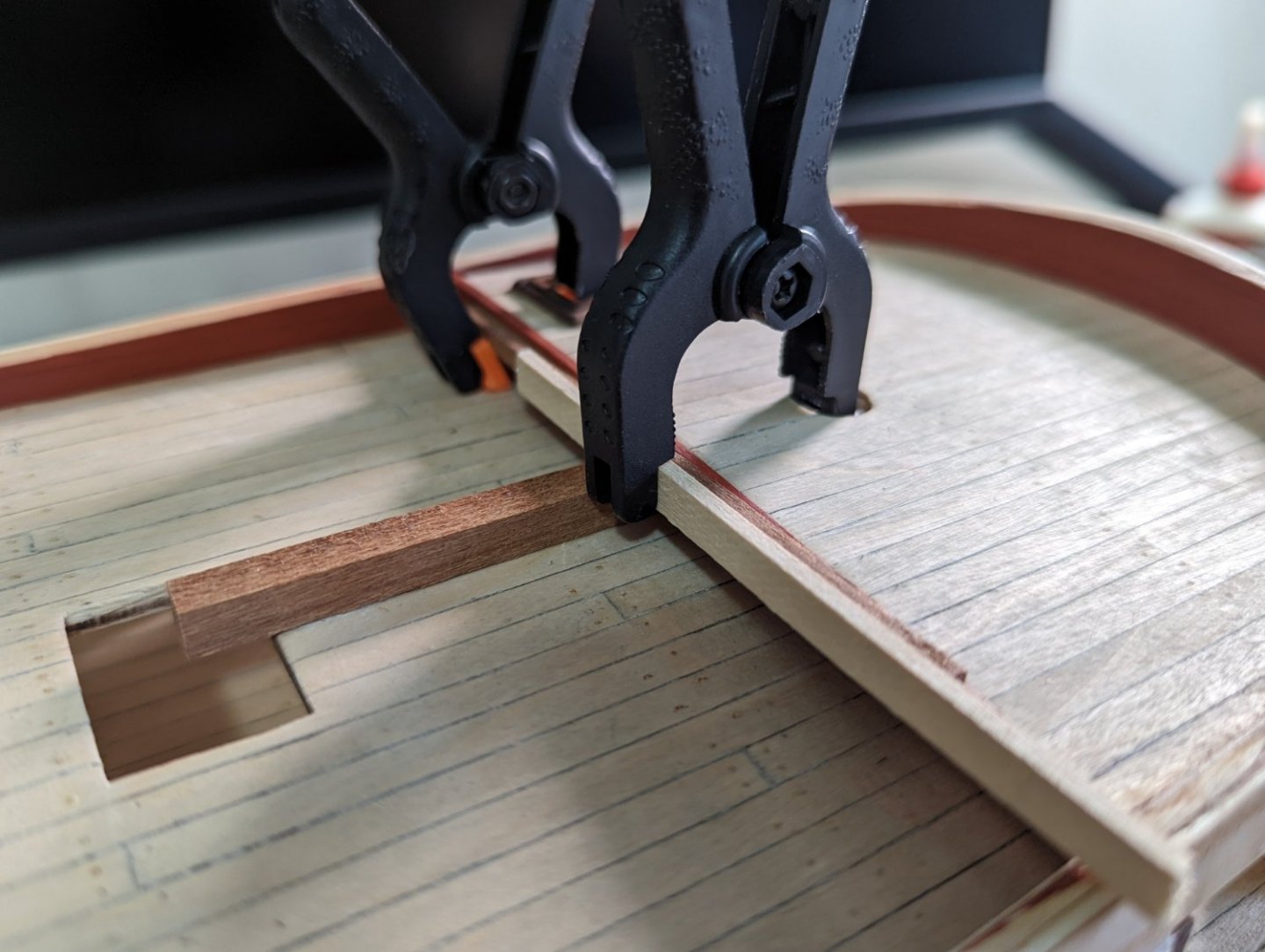
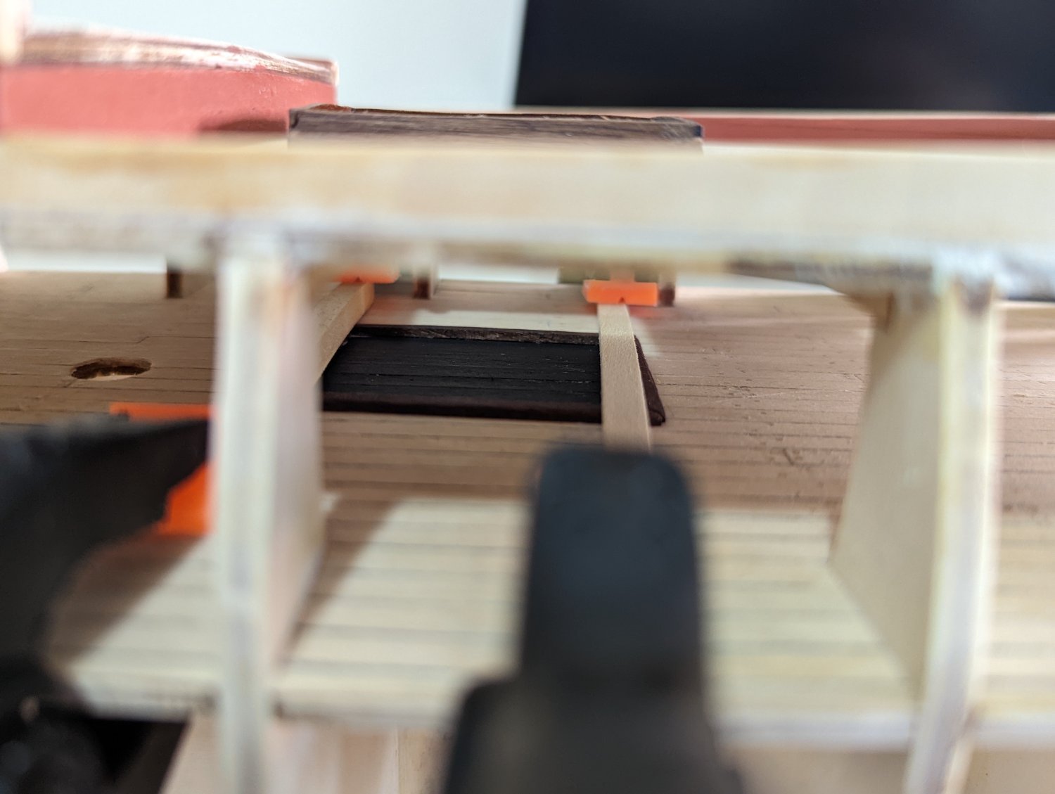
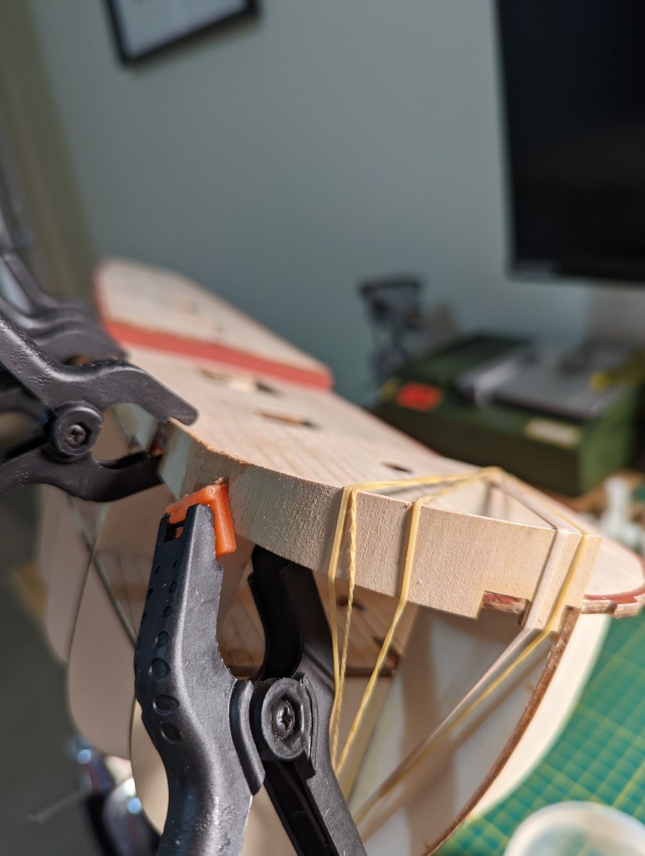
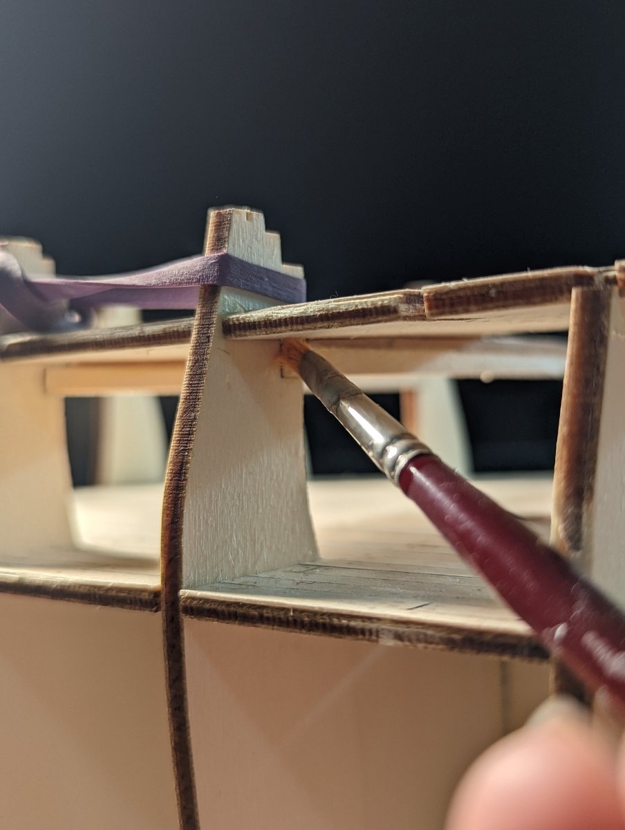
The wall facing aft towards the upper deck required a little bit of installation. The instructions called for a 2mm strip of wood between the deck and beam. It was a job to ensure this strip was exactly centred and then buff against the deck and bulkhead supports.

There was much clamping to let parts dry to the slight bend.
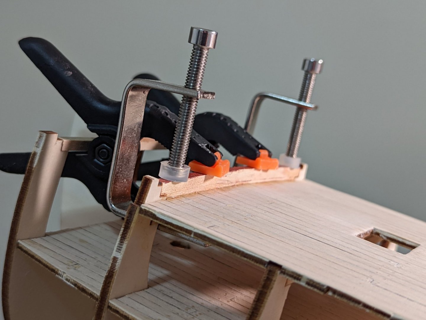
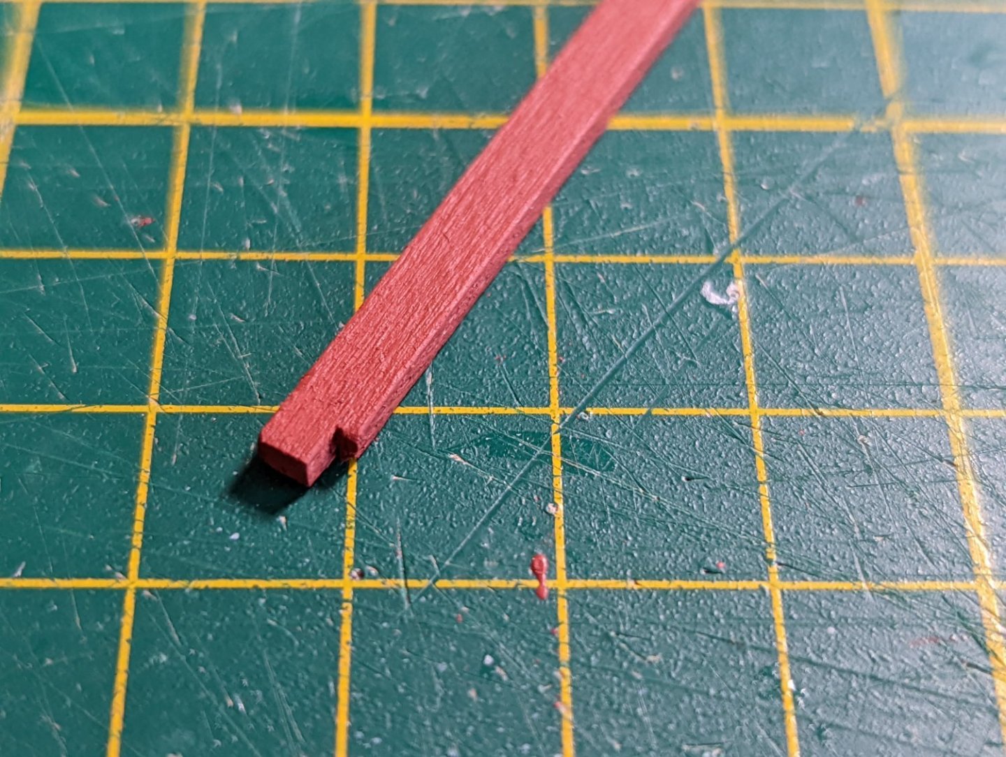
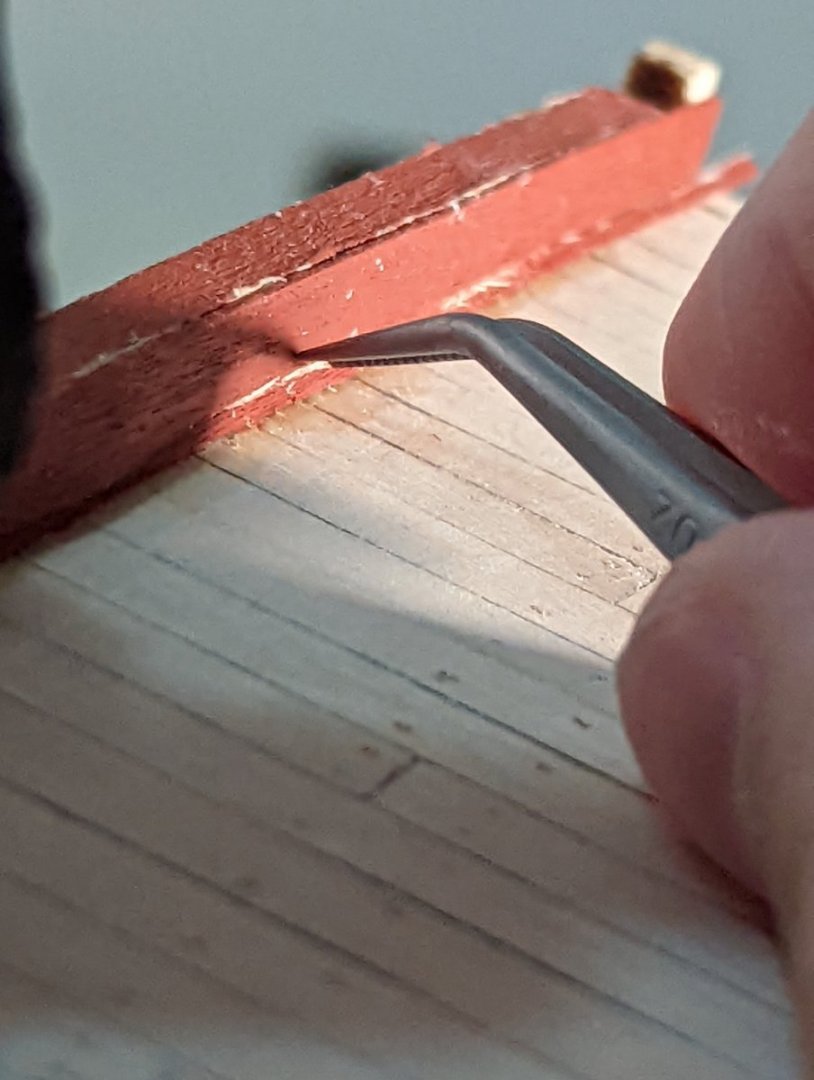
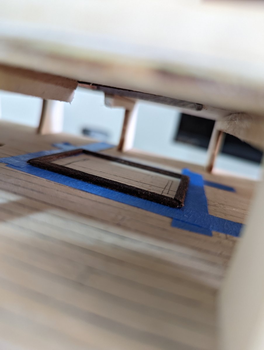
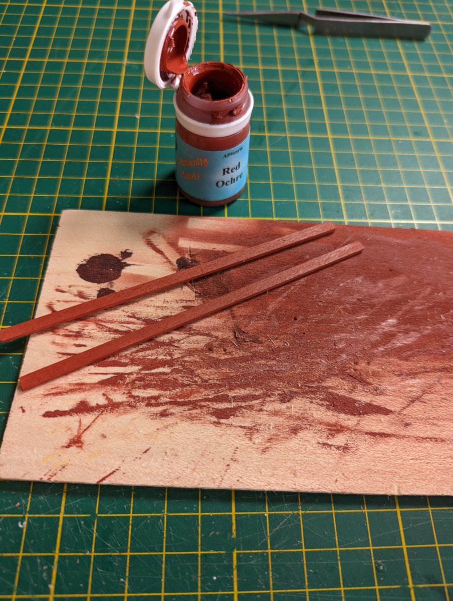
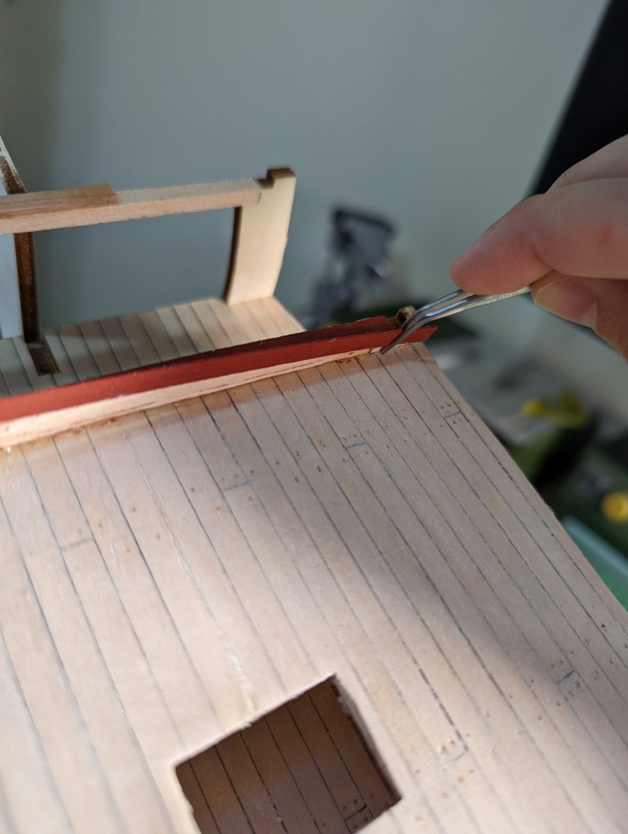
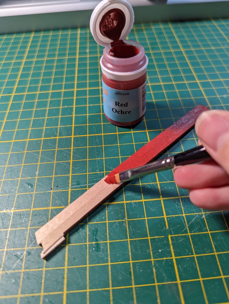
This wall required a panelled face in the 0.6mm decking timber. I pre-painted this red ochre before installing.
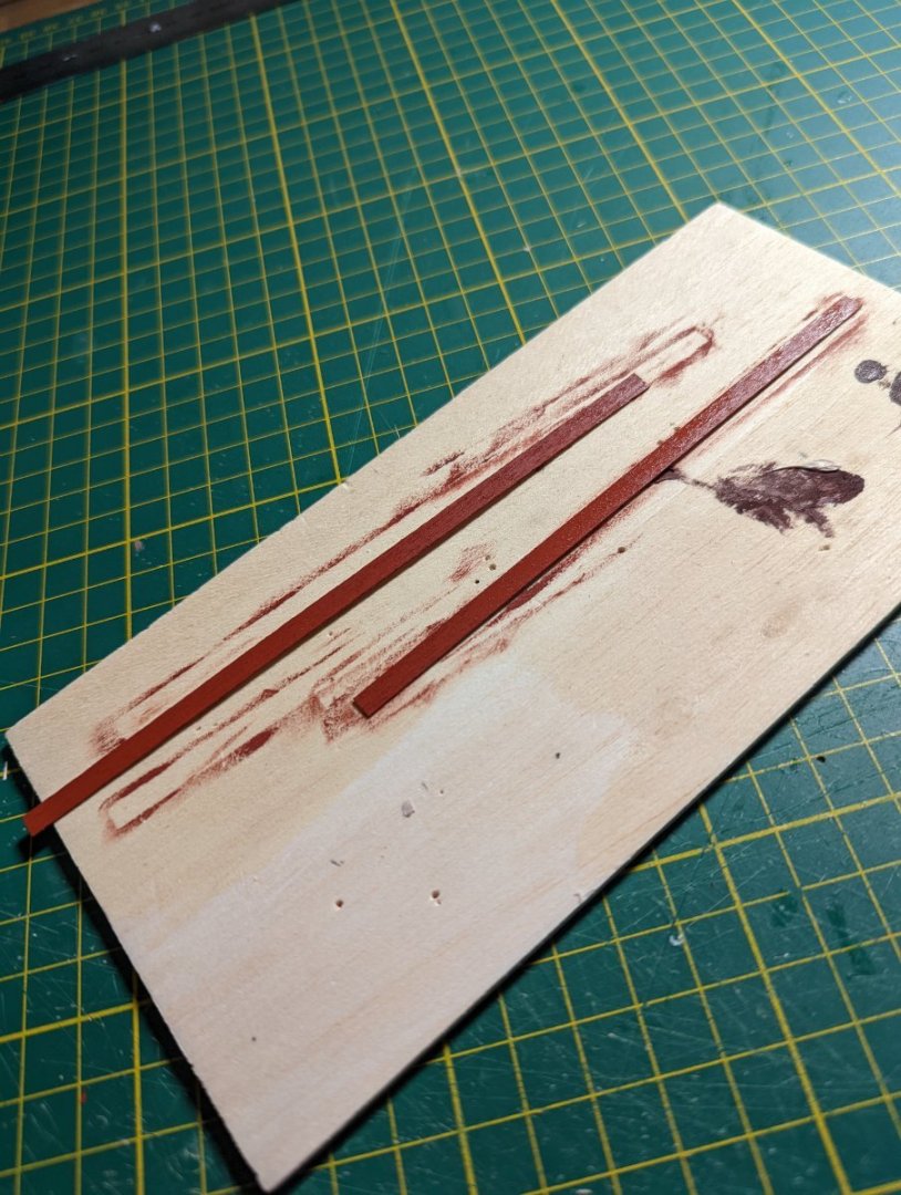

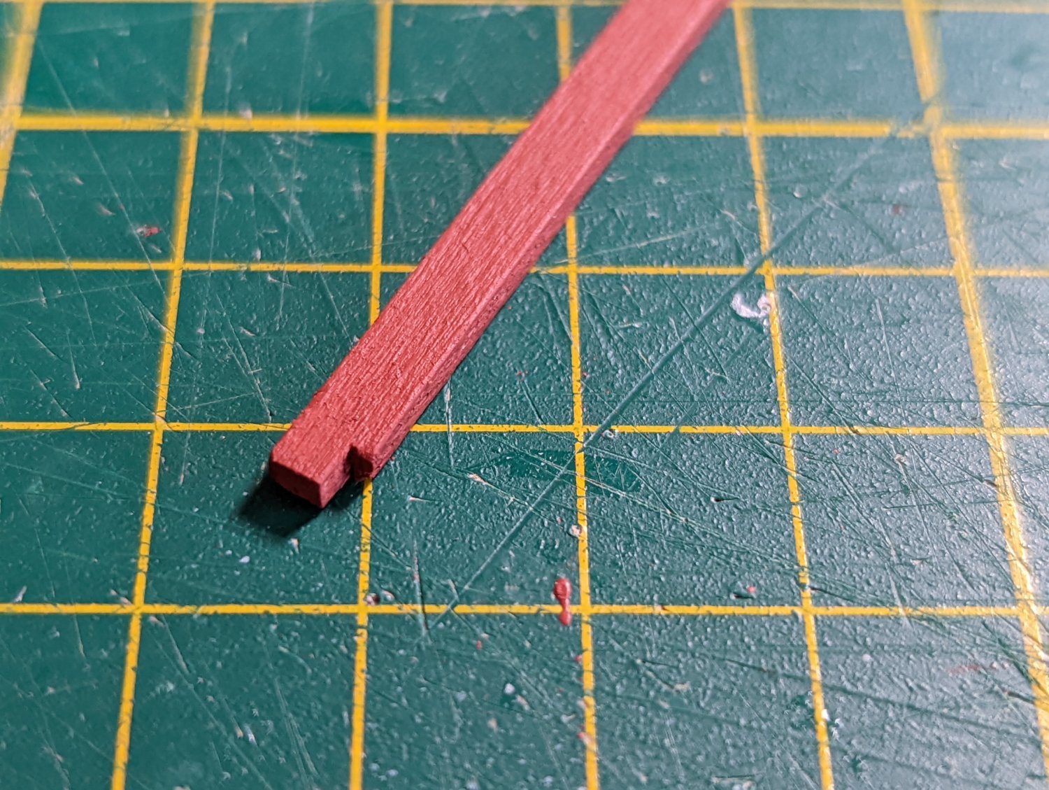
The trickiest part was measuring and cutting the thin strip of red panelling between the deck and the top-most panel. I used tweezers to push it gently in place after dry fitting.

One of the next steps requires fitting the bulkwark around the ship. Before jumping into this, I've paused and am doing some research.
The bulkwark will be very visible even at the end of the build. Aside from needing to be careful that the bulkwark is clamped straight against the deck with no gap, I also revisited my references to check what the bulkwark looks like.
At this stage I noted the replica (as well as several builds on MSW) have these painted and without adornment. Reading through the instructions, I noted that these bulkwarks will be clad with 2mm thick wood down the line. This means I don't have to paint the bulwarks at this stage.
On my perusal, however, I noted Marquardt and the replica have recorded the Endeavour's waterways; the replica's are red.
I hadn't planned the pattern to include waterways but I figure, at this stage, it's the only time I have left to give it a good crack before altering the edge of the deck becomes more difficult.
So, before installing the bulwarks, I'll make the waterways.
The other thing I'm starting to read and consider is installing reinforced pilot holes for pedestal stand supports. If I'm to do that, now is the time.
-
Thanks, Steve -
I'll be sure to cut the beam away tomorrow. Really appreciate the advice! I can't imagine this beam would be practical in a real ship haha.
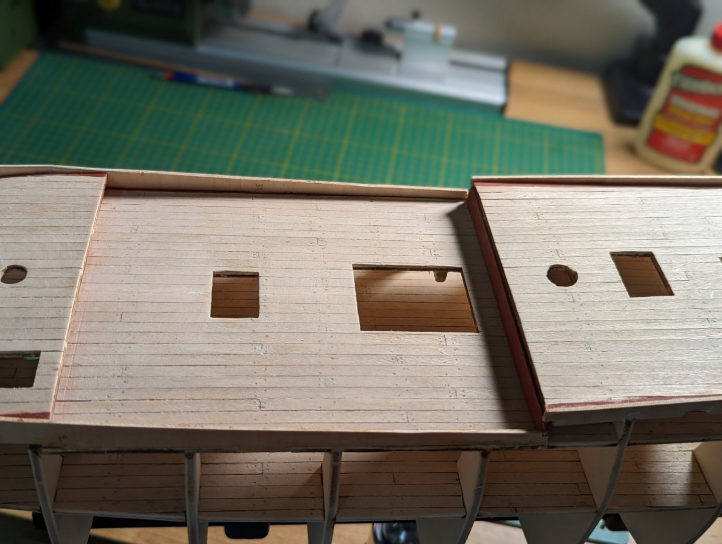
FITTING THE QUARTER DECK
I amended the upper, quarter and forecastle decks to shipaholic's recommendation, and then got to fitting the quarter deck.
This required a good bit of generous wood glue and many clamps to keep the deck against the camber set beams.

I note that the bulkheads sit out of the deck in some places substantially. I imagine this will be addressed when faring the hull before planking.
-
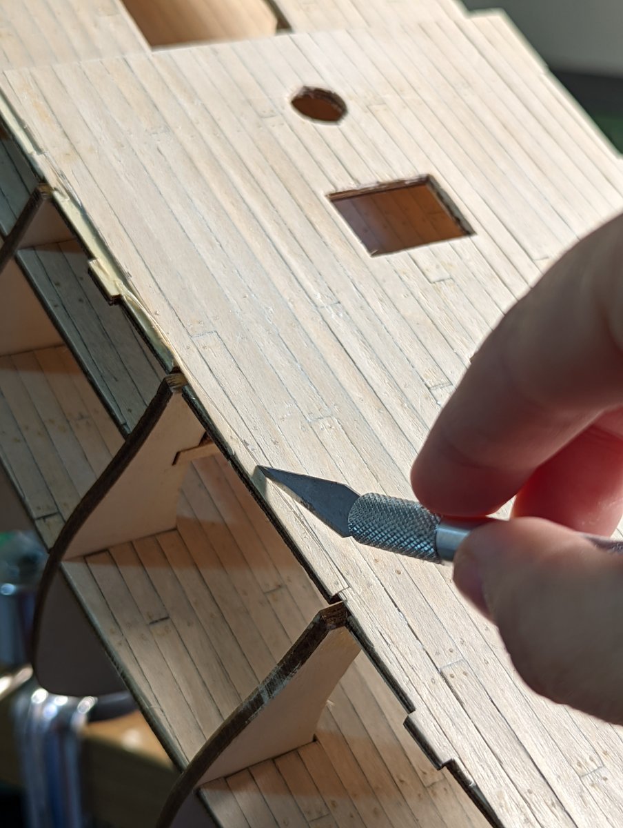
1 hour ago, shipaholic said:
Hi Kristyn,
something I just remembered from my build and something I should have realised to advise you of earlier. You should have planked the upper decks after fitting them so as to cover up those notches where the frames are. Not sure what the Occre instructions say about when to plank the decks.
Very good catch! Not to worry, I can amend these easily enough by replacing the outermost planking against each offender.
Thank you - appreciate the heads up! The OcCre instructions leave much to be desired at times, as I'm sure you can appreciate haha.
-
I really like your narration and the care you're taking with the photos and descriptions, Masa.
I'm pulling up a chair to watch this progress!
Kristyn
- Knocklouder and Dave_E
-
2
-
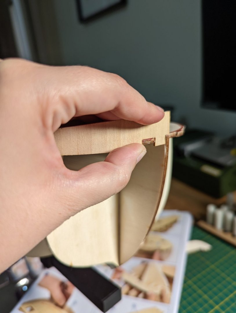
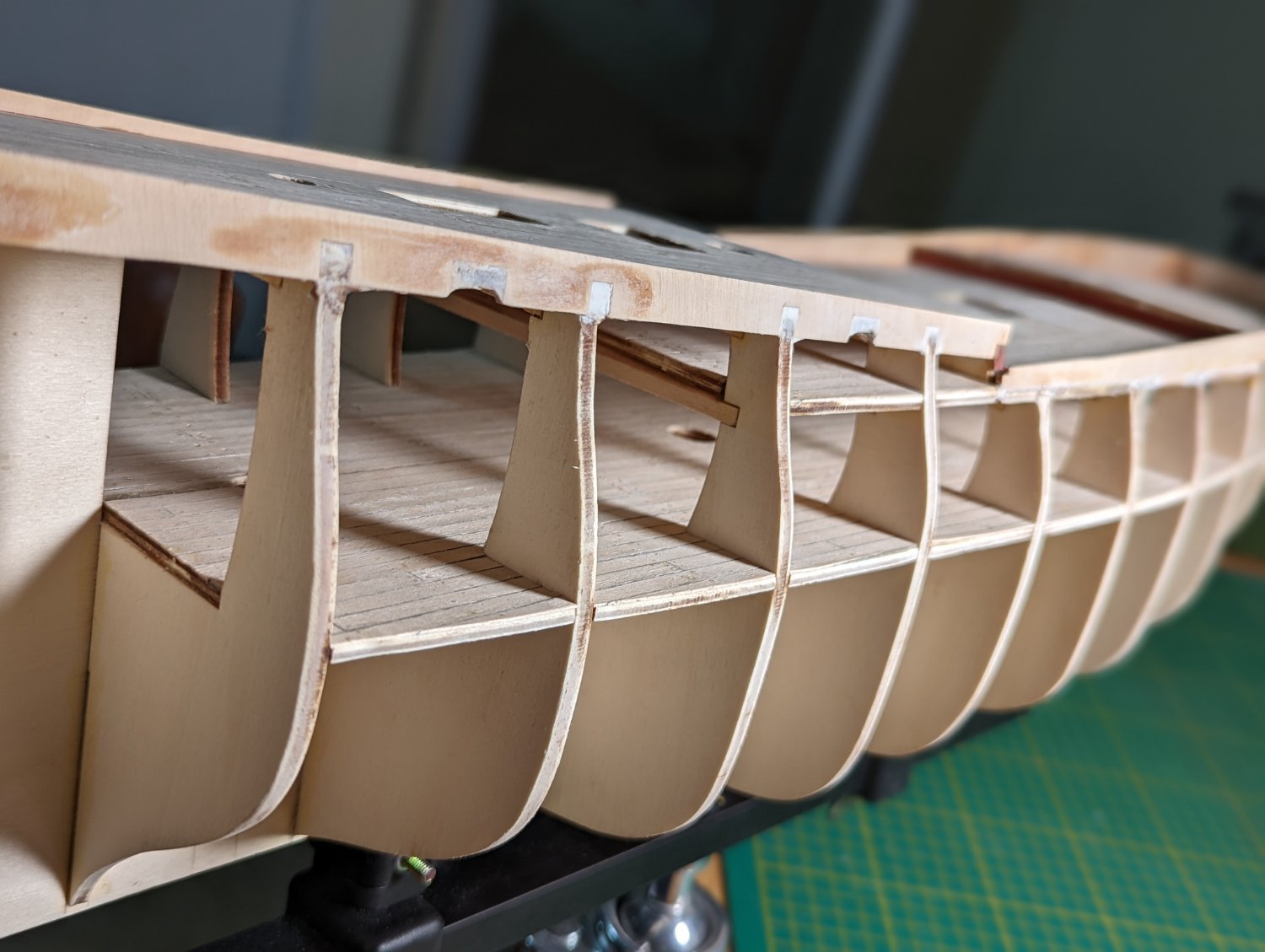
INSTALLING THE QUARTER DECK BEAM SUPPORTS
I followed the same process as I had undertaken for the upper deck to install the support beams of the quarter deck.
Forward of the main mast the quarter deck ends. This wall (I can't find what it's called on a ship) will be visible between the levels of the upper and quarter deck so I wanted to pay special attention to it's finish.
This wall required minimal assembly and some clamping.
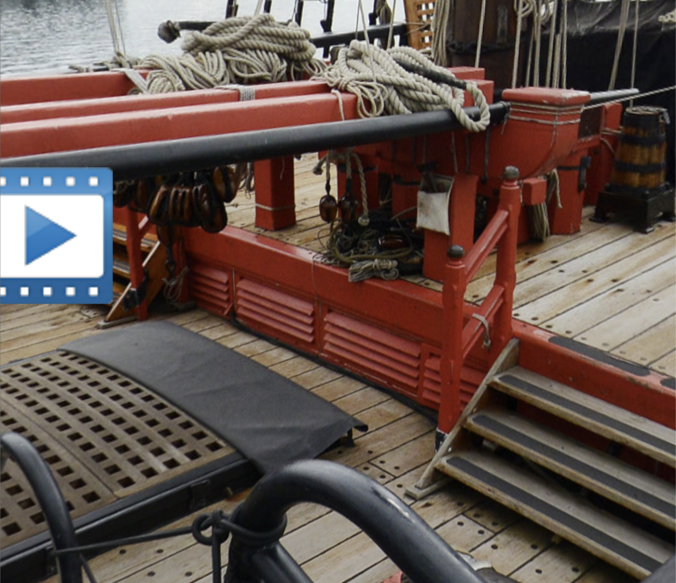
I wanted to check what this looked like before gluing down, so I persued my references and other Endeavour builds on MSW.
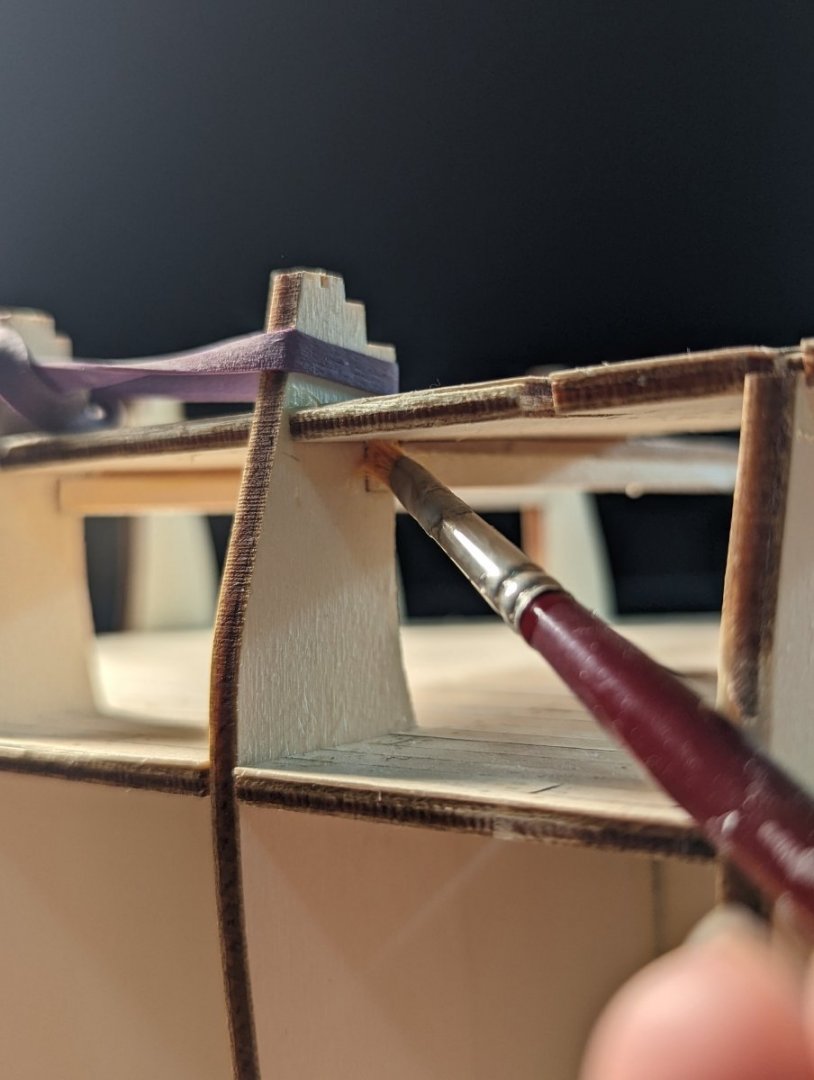
The replica Endeavour has this wall painted red (along with some additional details like vents).

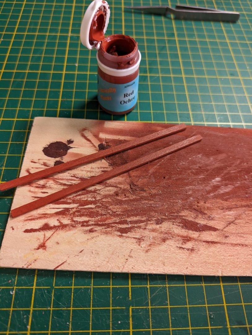
I painted the face of this part in Red Ochre (from Admiralty paints) before gluing it down. This will save me accidentally getting paint on the deck later down the line.

I then cut and sanded down each of the beams and camber blocks. This followed the same process as my previous post so I won't elaborate except with photos.

While I wanted to install the deck tonight, I will things dry overnight.
The camber from the upper deck requires the red wall to bend and I want to make sure the glue is properly cured before putting additional strain on it.
- Gregory, Dave_E and Prowler901
-
3
-
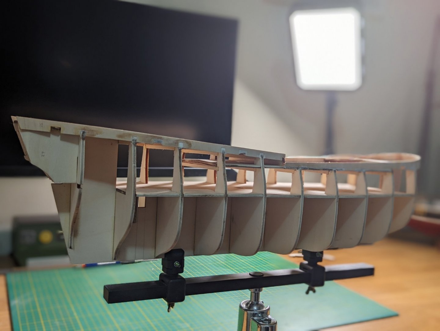
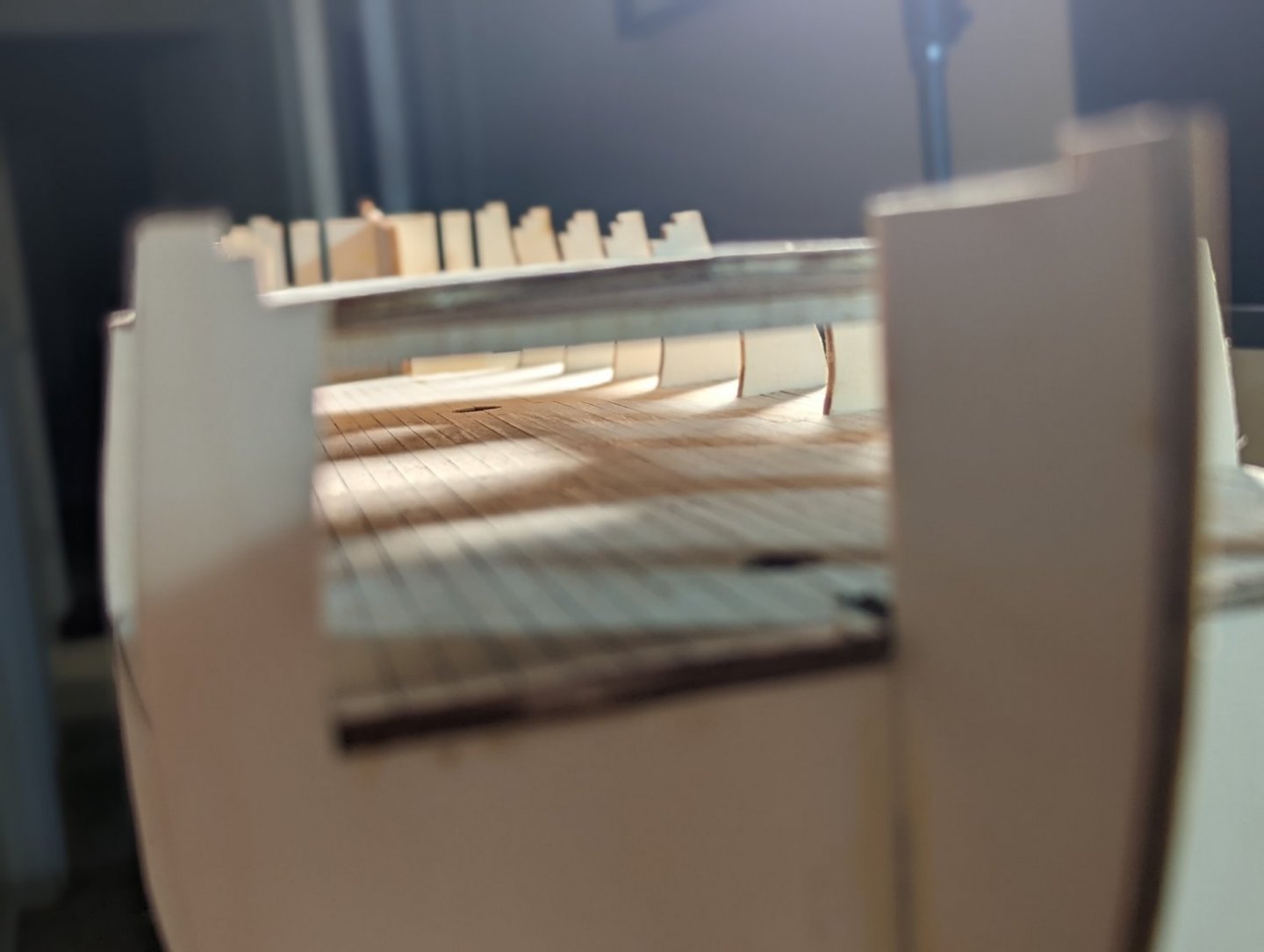
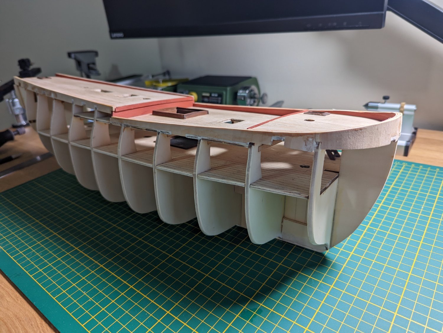
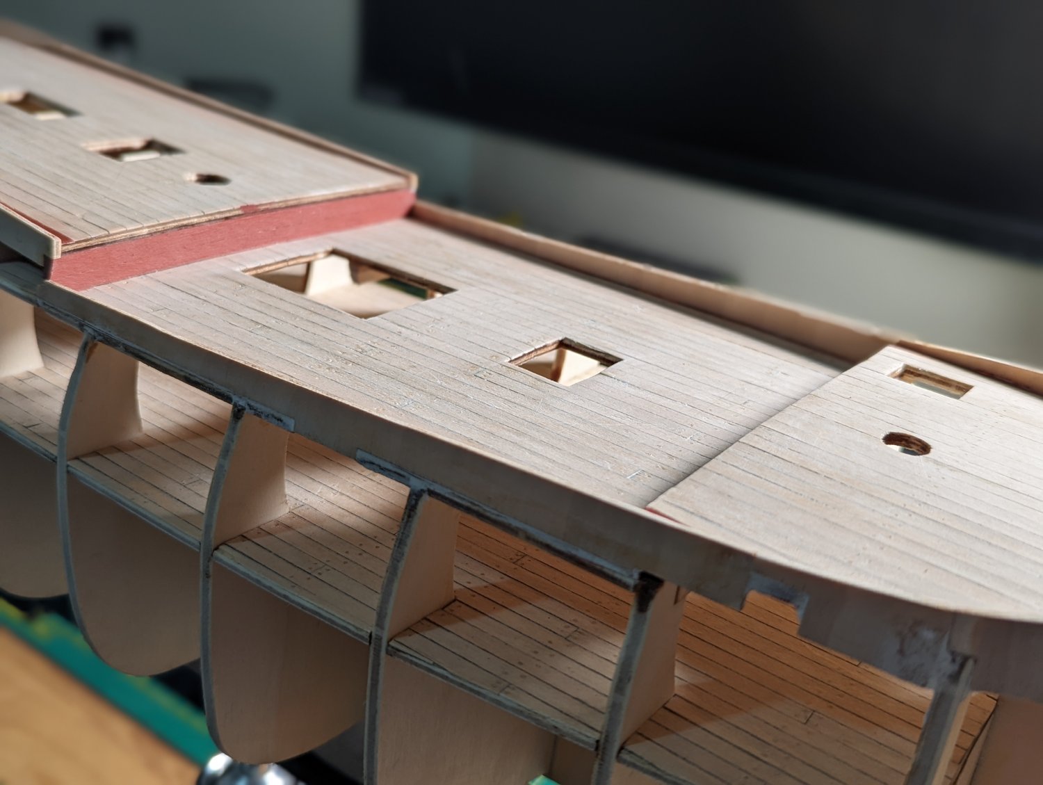
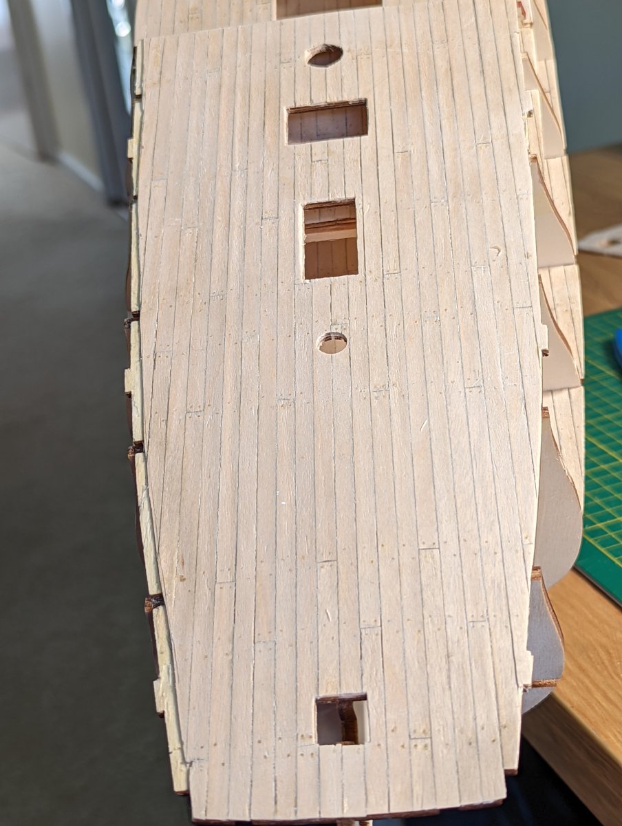
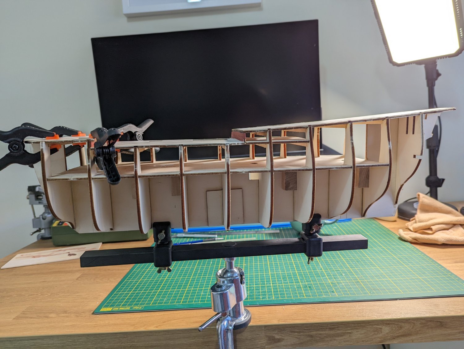
INSTALLING THE UPPER DECK
After the camber blocks had cured on the beam deck supports, I installed one half, then the other of the upper deck.
It felt good to get to this stage after so long preparing the decks.

Once clamps were off, I ran a bead of woodglue underneath along each seam to seal the deck and ensure it was solid.
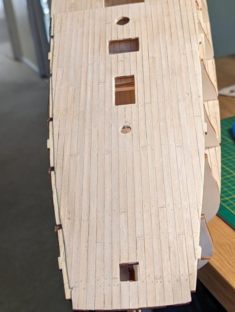
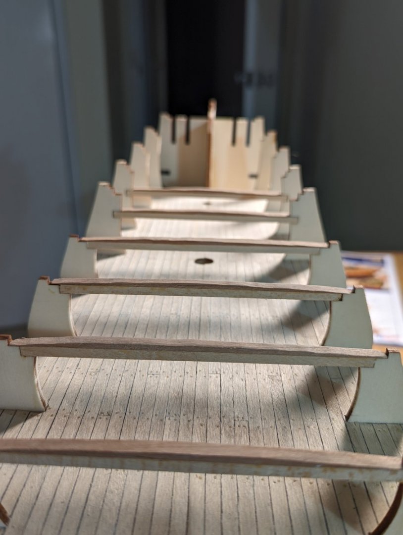
Enjoy some close up of the details with the upper deck fitted.


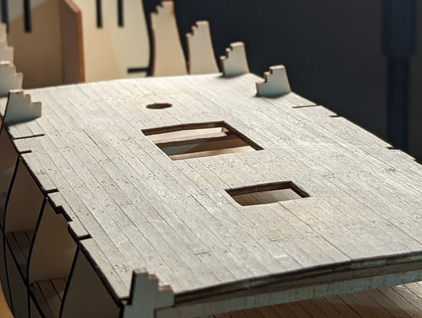
Rest assured that I reclamped after taking these photos and will leave overnight. This ensured no gap between deck and beam.
Next up I will install the forecastle and quarter decks and their camber.
Kristyn ⛵
- Gregory, Dave_E and Seventynet
-
3
-
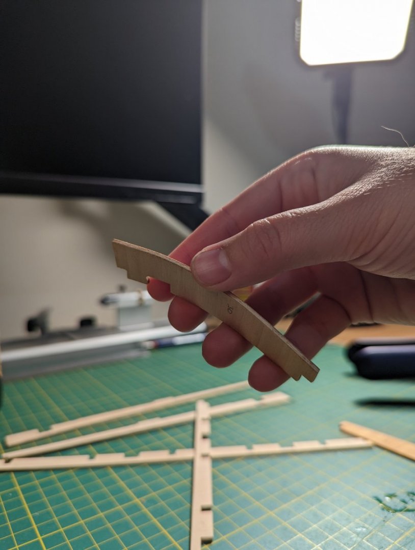
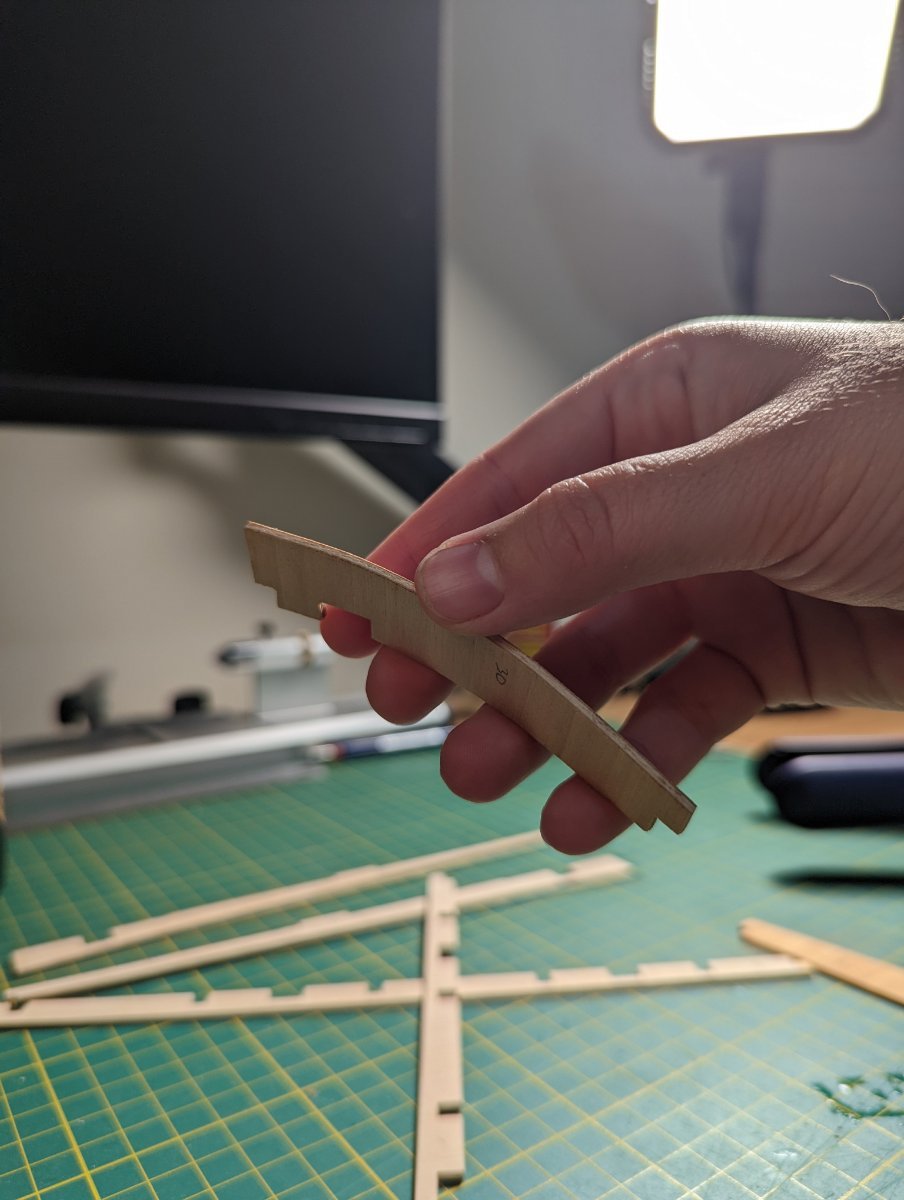
INSTALLING CAMBER ON THE UPPER DECK
Today I had a hand at installing the upper deck, including the camber blocks as per discussion.
To do this, I first measured each of the widths of the deck beams and drew up some templates for the camber (6" for the upper deck and forecastle deck).
I remembered I had a flexible curve ruler in my art box, and used this instead of nails as I had shown previously to draw the arc.
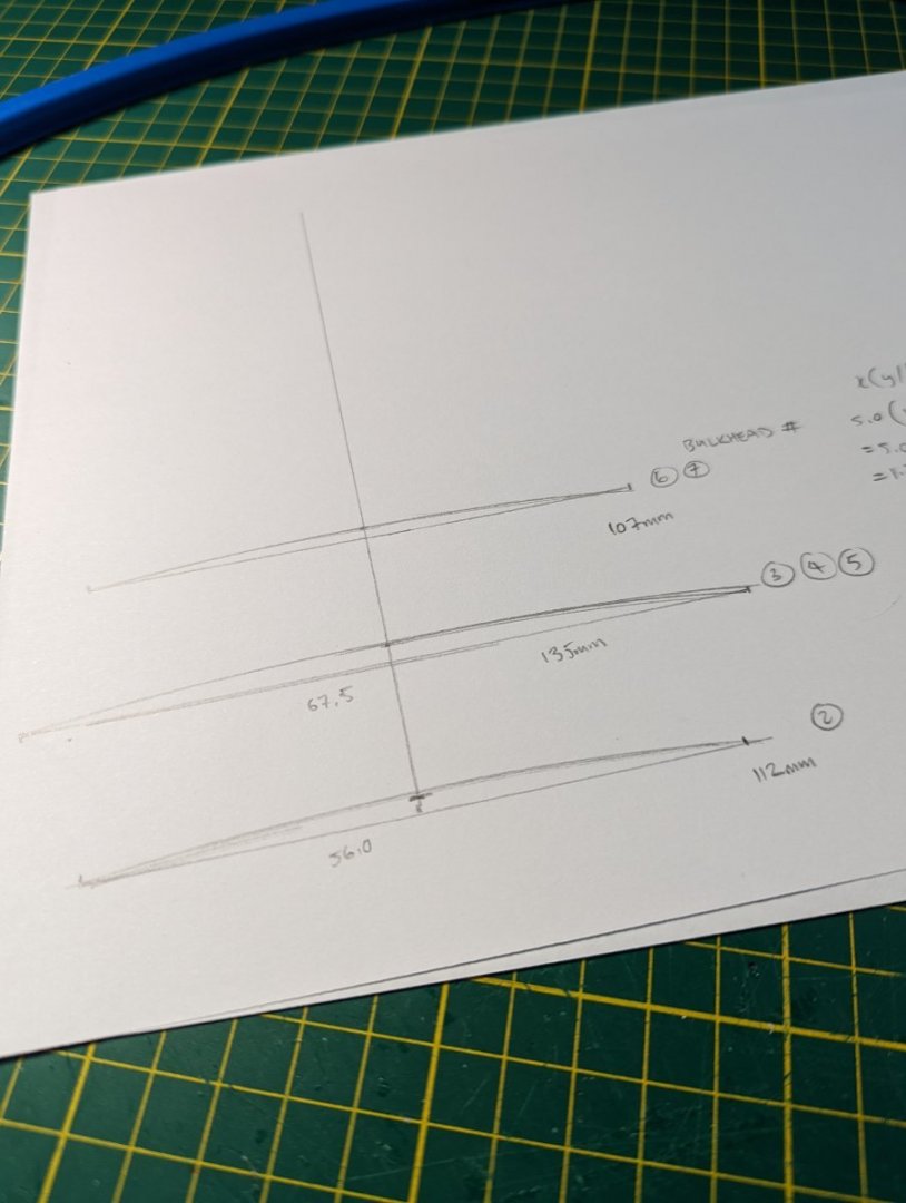
I cut the 5x5mm cherry to its respective lengths and glued the template to one side.
I then sanded down the block, checking that the midpoint sat at 2.8mm, and that the arc was symmetrical.


Once all six camber fillers were dry fitted, I glued each down and clamped them square to dry.
And all dried, ready to install the upper deck.
- Gregory, Seventynet and Dave_E
-
3
-
7 hours ago, shipaholic said:
[...] as you move aft on the quarterdeck the amount of rise at the centre of the deck needs to reduce, i.e the diameter of the curvature remains the same as the deck width narrows. So at the aft most beam the centre is only raised about 1 mm.
Ah, yes this makes sense - given the maximum beam (the width of the deck) is a variable... the narrower the deck, the less the camber.
I'm visualising instead of a cylinder now, a hemisphere (if that makes sense) that the deck flows around
I wonder is that to ensure that water not only naturally runs off to the sides but also may run aft? The place closest to the ship's centre is highest.
Is this variation only on the quarter deck or on the upper deck too?
-
Henke,
What a superb build and beautiful ship!
- TrunkMonkey, VonHoldinghausen, Henke and 1 other
-
4
-
EXPANDING THE WORKSHOP
I have good news and bad news.
The good news is that I have convinced the admiral of my need for a table saw. The admiral is bemused by this hobby, but tolerates it for my enthusiasm. Many warnings about counting fingers.
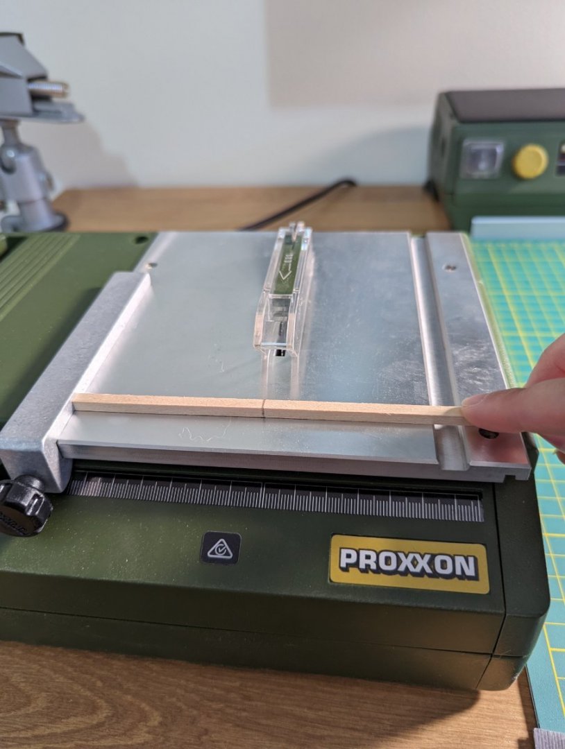
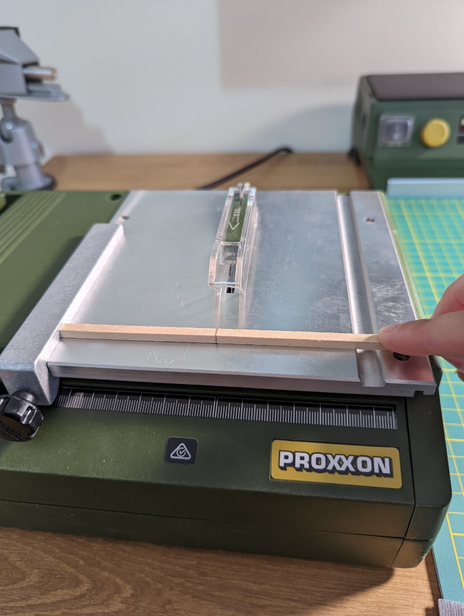
The bad news is that the Byrnes table saw, as with the drawplate, is just unjustifiable for its shipping costs to Australia. So I've settled for a nice entry level Proxxon KS230 that will get the job done and satisfy the admiral. Lose the battle, win the war.
It's yet to arrive but I'll do a little walkthrough once it's here.
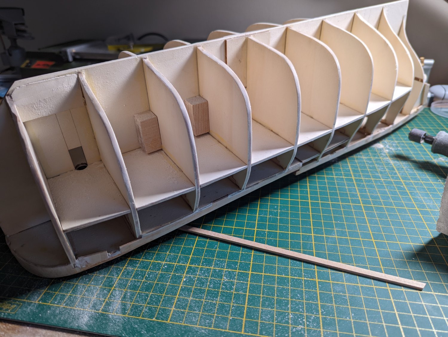
INSTALLING UPPER DECK BEAM SUPPORTS
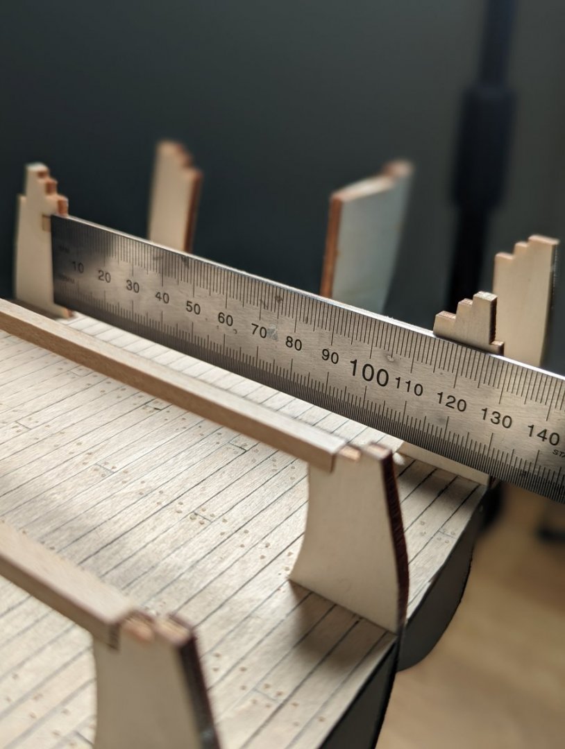
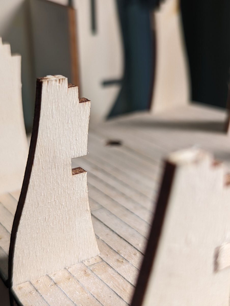
The next stage of the build is installing the beams for the upper deck. The beams are required for the 6 bulk heads immediately succeeding the first from the bow.
There are pre-fabricated slots on the relevant bulkheads within which each beam inserts.

The kit supplied 4x4mm limewood for the beams. It's a smooth material, good quality.
I hunt in my spare drawer and find a 5x5mm length of cherry I can use to craft the camber blocks on top of these beams after install.
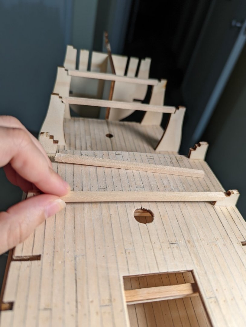
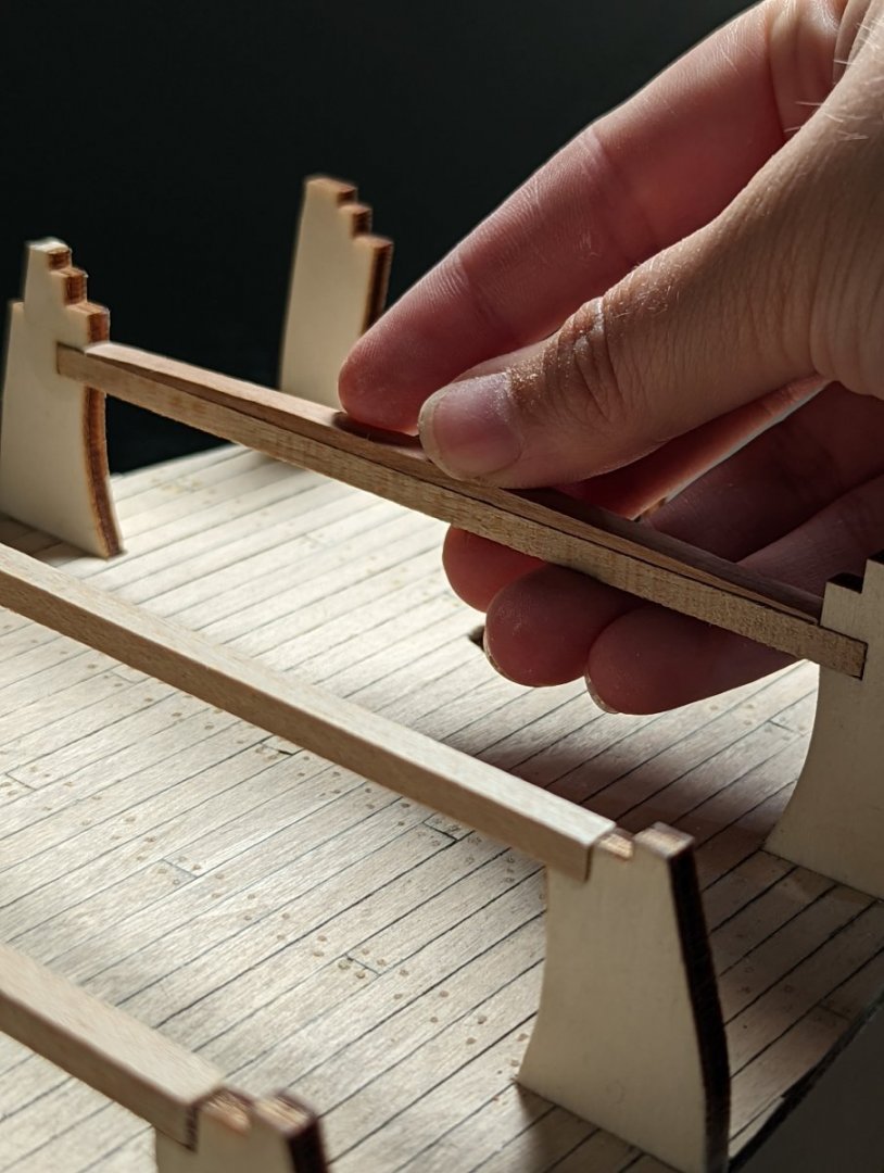
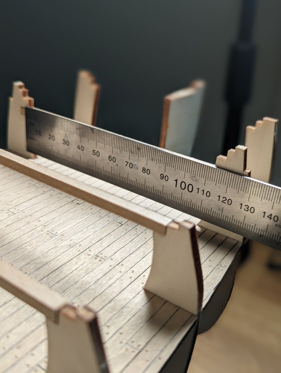
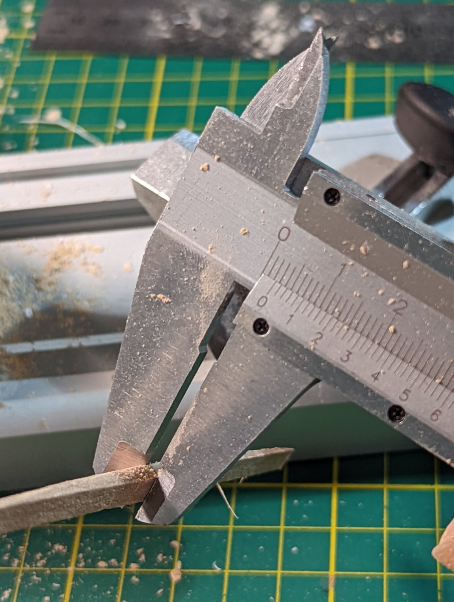
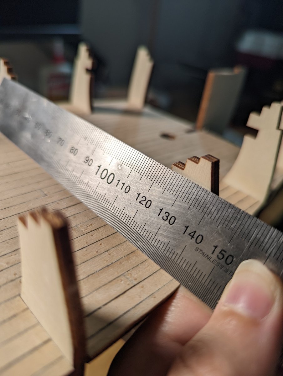
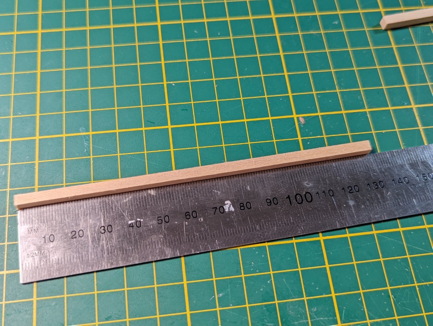
The instructions call for 125mm length on each beam - I measure the distance on the model itself to double check, and it's accurate.

I measure the 4x4mm limewood a little over, as I want to sand back slowly to ensure a super snug fit.
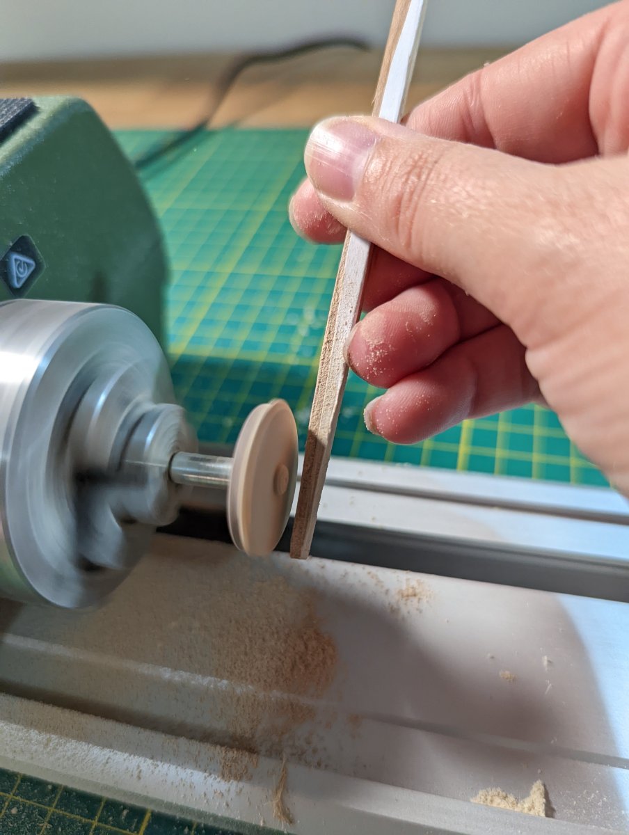
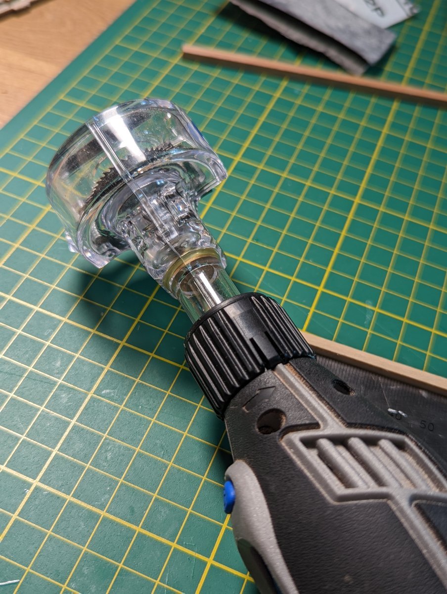
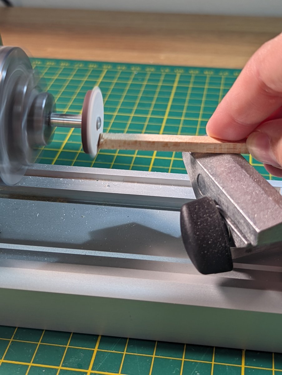
As my table saw has not arrived yet, I use my Dremel saw attachment to cut the lengths. I'm not as accurate as I'd like to be with the Dremel so allow for an error margin.
I then use my lathe moonlighting as a disc sander to sand off the excess until each beam fits snugly.

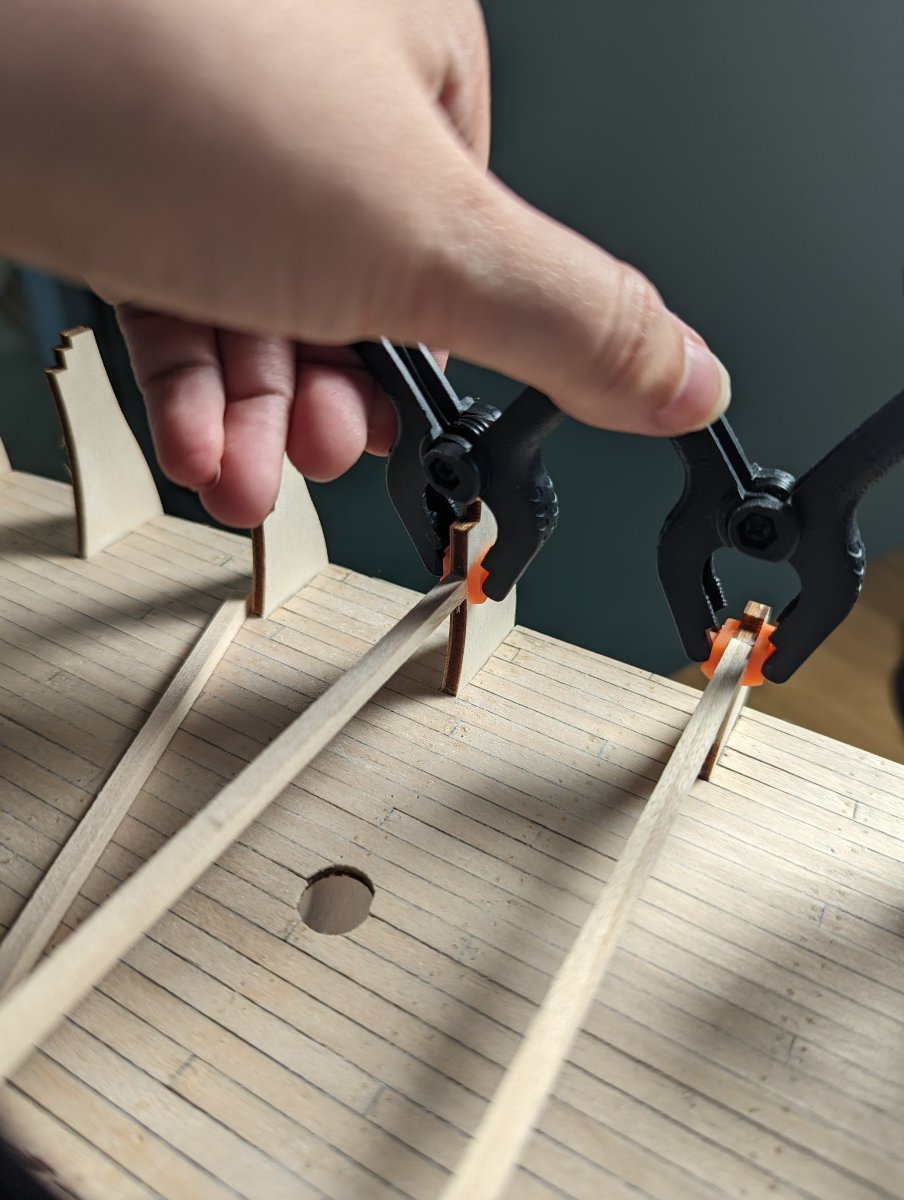
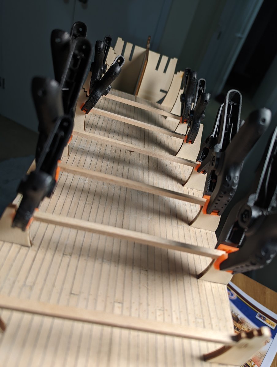
I dry fit each in place before then gluing them down with wood glue.
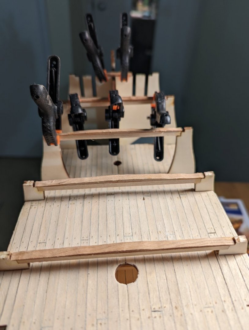
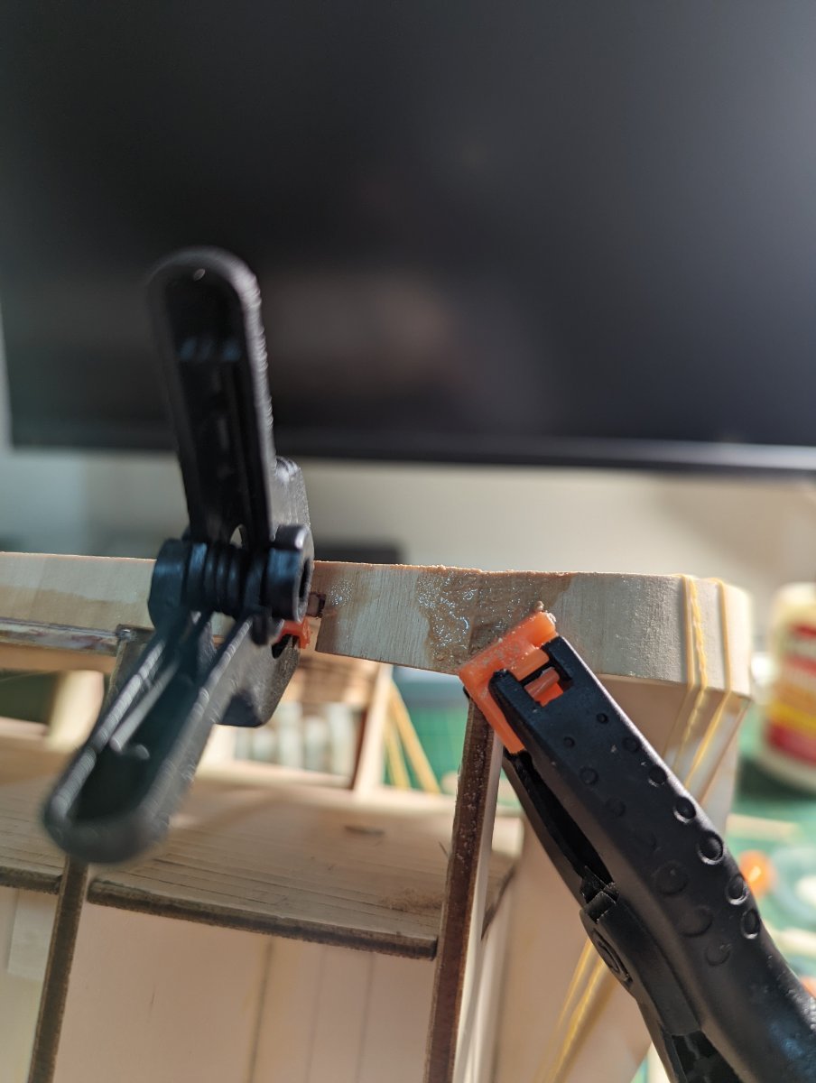
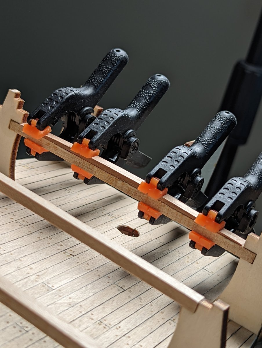
As it dries, I make sure to clamp each beam square against the bulkheads.

Next I'll create the filler blocks following the template for camber created earlier.
- Seventynet, Prowler901 and Dave_E
-
3


HM Bark Endeavour by KJackson - OcCre - 1:54
in - Kit build logs for subjects built from 1751 - 1800
Posted
Thanks, Gregory and Steve -
I see the stealers - thanks, Gregory. My knowledge is theoretical only at this point and I haven't done them in practice!
To Steve's point, I'm very glad this will be the first (and hidden!) layer of planking. I'm going to try my hardest to make it look good purely so I can get better at planking from a technical point of view. At the end of the day I'm treating it as a dressed rehearsal for the final event.