


rtropp
-
Posts
915 -
Joined
-
Last visited
Reputation Activity
-
 rtropp reacted to EdT in Young America 1853 by EdT - FINISHED - extreme clipper
Young America - extreme clipper 1853
Part 147 – Ship’s Boats 3
In the last part the frames were installed on the port side of the plug. The first picture shows the starboard side framing in progress.
The frame strips were left to soak in water overnight, making them very flexible. They were then brushed with glue where they would mate with the opposite frame and the keel and then pushed under the keel. Each frame was then pinned down at both ends and sometimes in other places as shown in the picture.
The next picture shows the topside plank on the starboard side being installed against the nailed guide strip.
I intend to leave this side unplanked to show the framing, so only the wale below the top plank will be installed on this side. On the other (port) side, the nailed guide strip and this top plank were also installed. The next picture shows the keel rabbet being pared out on the port side to prepare for the garboard strake.
The rabbet at the deadwood and on the stem were pared out first with a V-gouge as shown in the picture. These areas were then cleaned up and the remainder of the keel rabbet formed using the barette file shown in the next picture.
The garboard strake was then installed as shown below.
Back on the starboard side the channel wale was installed just below the top plank while glue was drying on the port side planking.
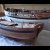
I mentioned earlier that all the work shown above was done on longboat two, the second to be made. At the same time, work was proceeding on the first boat. The next picture shows that boat fully planked below the channel wale on both sides. The wale has been temporarily inserted so the top plank can be glued on.
As on the ship’s hull, boats will be painted, and the channel wales shown in a contrasting color, so they will be glued in after painting of both the hull and the wale to ensure a clean line. In the next part I will pick up on work to finish longboat 1.
Ed
-
rtropp reacted to Chuck in HM Cutter Cheerful 1806 by Chuck - FINISHED - 1:48 scale - kit prototype
Just a small update. I worked on the inboard stern details. The seats are completed. Card templates were made first using the plans as a guide. Then they were tweaked to get a nice tight fit with the parts.
Cleats were added...these are all laser cut Syren cleats (5, 7, and 9mm). All that was needed to do was sand them a bit to shape and then add a piece of wire as a pin. Then they were glued into place. I decided to paint these bulwark red also to match the many contemporary models I have seen.
Finally....the horse was added for the boom sheet. This was just a small piece of wire bent to shape. Two small washers laser cut from paper were added to finish it off nicely on each end. They were painted to look like metal. I should have dusted the model better before taking the pics....next time
I will now continue my way forward along the bulwarks adding eyebolts, cleats, ladders and pin rails.
Chuck
-
 rtropp got a reaction from EdT in Young America 1853 by EdT - FINISHED - extreme clipper
Ed,
At what point in this build did the first Young America book end?
Thanks
Richard
-
 rtropp got a reaction from Piet in Young America 1853 by EdT - FINISHED - extreme clipper
Ed,
At what point in this build did the first Young America book end?
Thanks
Richard
-
 rtropp got a reaction from mtaylor in Young America 1853 by EdT - FINISHED - extreme clipper
Ed,
At what point in this build did the first Young America book end?
Thanks
Richard
-
rtropp reacted to GDM67 in HMS Naiad 1797 by GDM67 - 1:60 - using Ed Tosti Books
Stem - Keel - Stern:
Progress is slow and steady on the Naiad. The entire backbone of the ship is all glued up and sits on the shipway, ready for the finishing touches before framing begins.
The Stem and Head of Knee all ready. I cut the gammoning slot using a small drill bit to puch out successive holes and then cleaned it up with a file. If I were to do this again, I would cut the gammoning slot before tapering the piece! I had to angle the part so the slot would be perpendicular to the piece when fayed to the stem. Also, if you are temped to not make the jig for tapering the knee of the head as outlined in the book (as I was), then you run the risk of having a bent nose to your ship (trust me on this and learn from my badly chosen shortcut). I was able to correct the "bent nose", but the part could have been perfect, not just very good...
I still need to cut the rabbet as well as install the copper nails. I ordered some antique copper wire in 22 and 24ga. for this purpose and will show it once it arrives.
I am very happy with the stern deadwood structure. A simple structure that was tricky to make due to all the angles. In the end, just study how this should look on the real ship and then execute. Its all very logical once studied.
This is how she sits on the slipway. I am very pleased with the results. There is a subtle taper fore and aft on the keel structure that I have never inclued in my previous models. This is a really nice touch and is a result of precise plans and research by EdT. My hat is off to him again for creating such a wonderful monograph.
I will be switching back to my US Brig Eagle to start the masting, and will start a log on that here next week.
All the best, Gary
-
rtropp reacted to GDM67 in HMS Naiad 1797 by GDM67 - 1:60 - using Ed Tosti Books
Hi Ed and Druxey,
Thanks for your follow up to my glue question. I will keep trying... Ed, I think you are right about the binding agent. This is exactly what I think happened.
Back to building. I have done some (more like a lot of) rework on the Naiad - I was not a fan of the knee of head and a few other areas, so I went back and redid all of this, ok, everything... It caused a lot of pain and as you can imagine, I was not motivated to take photos, but in the end, I am very satisfied with the outcome and the decision. Hey, if I am going to stare at this project for the next four years, its got to be pleasing to my eye.
The biggest issue was that I had drastically undercut the bow and made the entry much too fine. I tried to overcome this as I placed the forward cant frames, but simply found that it altered the beam of the ship drastically. So over I started. Needless to say, there was a day of depression...
33 hours later, here we are with a new keel, stern deadwood and head of knee. I find that I am much smarter the second time around.
Some lessons I have learned on this build:
1. Chisel instead of #11 blade (too late for my left index finger...)
2. File instead of sanding stick
3. Razor blade instead of sandpaper
4. Micrometer that measures thousandths, not hundredths
5. Successive pieces glued together have a cumulative affect on the size of the subassembly. Constantly refer back to the plans and templates - adjust accordingly.
6. Keep a "Ships Daily Log". Even if there are doldrums, record in it each day. Hey, they had to do it at sea, so why not do it at home???
7. Don't final sand or final shape a piece during the subassembly phase. The risk of undercutting or misshapaing is significant. By waiting to do this, it will help to bring the entire project together as one.
Next up is the infamous Bollard Timbers and stem rabbet...
Wish me luck. G
-
rtropp reacted to _SalD_ in US Brig Syren by _SalD_ – FINISHED - 3/16" scale
This is one of the parts of ship building I like the best, running all the rigging. As a structural engineer it never ceases to amaze me how they ran the rigging in order to transfer the load from the sails, to the masts, to the shrouds and stays and then into the ship. After every line I put on I push or pull or twist the mast to see how it interconnects with all the other rigging, just amazing. Sorry…I'm just easily amused.
I finished up the lower fore mast shrouds and stays which were done pretty much like the main mast. Next the sheer poles and futtock staves were tied in place. I put the futtock stave on the outboard side of the shrouds but after reading up on them (after the fact) I think they should have been placed on the inboard side.
The futtock shrouds were installed next. A 3mm hook from the Syren Model Co. was seized to one end to attach to the eye below the top. The other end was wrapped around the futtock stave and seized to the lower shrouds. I used 8/0 fly tying thread for the seizing to keep the seizing small. The catharpins were done next as described in the instructions.
Sorry for the blurry pictures
One thing I realize now but not at the time I was doing it is that I could have rigged the entire lower masts without installing the top masts. It would have been so much easier to install the shrouds on around the mastheads and not have to worry about breaking the top masts off. Would have been easier just stepping the lower masts too. Next time.
-
rtropp got a reaction from mtaylor in liquid hide glue comments
Thanks all for the insights.
I will play with some and see how if works for me.
Richard
-
 rtropp got a reaction from Shazmira in US Brig Syren by rtropp - Model Shipways - 1:64
Hi all,
Its been the summer from hell but I am finally able to get back to my Syren.
I thought I would begin with a photo of its current state which is a few rows into the coppering. It was not just a question of figuring out the stamp, but also learning how to use the tools. I will post my coppering saga in another post when I have more time.
I was not thrilled with how the deck came out. Not all of the tree nails lined up as well as the should. I was at the point that I was seriously considering scrapping it and starting over. But, I realized that I still do not know what mistakes I have yet to make. So, I decided to continue on with this. I figured some of the deck furniture / cannons would cover up some of the mistakes and it should end up ok.
Richard
-
rtropp reacted to EdT in Young America 1853 by EdT - FINISHED - extreme clipper
Young America - extreme clipper 1853
Part 144 – Monkey Rail 2
Happy Valentines Day, everyone.
After making and polishing the rail stanchions holes were measured out and drilled in the center of the main rail and in most cases down into the toptimbers below. The stanchions were then inserted into the holes for a depth check. A single rail section for each side was then curved to match the poop profile. The stanchions were then removed from their holes and threaded on to the rail in order. The next picture shows the next step – epoxy gluing the stanchions into their holes.
The end of the rail was first inserted into the inverted U bracket at the stern. All of the stanchions were then inserted into their holes, then lifted for gluing starting at the stern. The clamps in the above picture are lightly pressing the stanchions down where needed until the epoxy sets. The next picture shows the last stanchion on the starboard side being glued.
The rail was crimped in the aft stanchion then touched with a drop of CA glue. The others are free to move along the rail at this stage. The forward end of the rail was bent to the athwartship direction at the foremost stanchion as shown in the next picture.
The stanchions along the breast beam were then glued into place with the rails inserted. In the picture above, the glue has dried and a section of stair rail is being fitted into the lower ball on one of the stanchions at the top of the stair. The next picture shows the stanchions loosely in place on the port side.
In this picture the port rail has been curved to shape and is ready for installation. The last two pictures show the completed monkey rail.
This last picture was taken before final straightening of the stanchions on the near side. Once everything was adjusted the top balls were crimped with pliers to hold them in place. The rail is, of course, quite exposed and susceptible to damage by careless leaning or bumping. I am trying to sensitize myself to this new problem. The days of turning the model over and shaking it to remove debris are over.
Ed
-
rtropp got a reaction from EdT in Modeling the Extreme Clipper Young America 1853
Ed,
I am starting to schedule my next build... which should be a while yet. I know you have not started it yet, but can you estimate when you plan to have Volume two of young america published?
Richard
-
 rtropp got a reaction from dgbot in US Brig Syren by rtropp - Model Shipways - 1:64
Thanks Sal, I appreciate the info.
As I look at the rails and cat head I am not completely satisfied. They are not positioned as well as I would like. I have already spent over a month but since I am not really in a rush I am considering removing, rebuilding and re mounting all of it. That would also give me a chance to try some ideas I have been offered for cutting the grooves, creating sheaves.
The good news is that I am getting good at "deconstructing." Bad news is that i need to be good at "deconstructing."
Richard
-
 rtropp got a reaction from GLakie in US Brig Syren by rtropp - Model Shipways - 1:64
I bought some finished stock from Jeff Hayes a while ago. Also I decided to mill my own so placed an order for box and Swiss pear from Gilmer Wood. https://www.gilmerwood.com. These came as rough planks but are a lot less expensive than buying pre-cut to size.
The boxwood in the pictures above were milled down from a 2" x 5" x 34" plank.
Richard
-
 rtropp got a reaction from egkb in US Brig Syren by rtropp - Model Shipways - 1:64
almost a month has gone by but I have finally finished this section of the practicum.
I decided to try and salvage the cat heads which had their top pieces too short. I took them apart, glued a piece to lengthen them and then installed. It was only a tiny extension so I needed to be careful when cutting and sanding after they were attached.
Next I worked on the middle rail, again building it from scratch using boxwood. I used the laser cut pieces as template first gluing the stock in layers then gluing the template.
Then added the rest of the structure.
Next I went to work on the bumpkins. I am holding off on installing them until later as advised by Chuck in his build log.
I decided to use my proxxon wood lathe to reduce a strip of 1/8 boxwood to 1/16.
I was having some difficulty stabilizing the back end. I had seen several suggestions but noticed some foam packing near the work table. I cut out a round piece and pierced it so I could push it around the end of the work piece. I then stuffed that into the tail stock.
Using sandpaper and files I reduced the bumpkin width to
1/16. (the thinning operation was too fragile for me to use a chisel.)
I did use a chisel for the end cuts.
,
then added the wire extension but will not cut them to size until installation.
While things on the bow were uncluttered, I drilled the holes to receive the bumpkins' wire inserts.
Finally I added the remaining structure sans bumpkins which I will hold until later.
The figure head is not permanently attached. Her face is a little flat so I wanted to look at it some more before deciding to keep or re-sculpt.
It came out reasonably well but I can work that looks "off" or "clumsy" in workmanship. After spending a lot of time fabricating the pieces, I seem to still have an unsteady hand when attaching them. I decided to try using a solid base for my hand while I am attaching or drilling. I have a piece of 8" by 8" by 17" bass wood and sanded the sides smooth. I is a little heavy but is a really solid hand rest when needed.
Now, on to the next section
Richard
-
 rtropp got a reaction from Canute in Modeling the Extreme Clipper Young America 1853
Ed,
I am starting to schedule my next build... which should be a while yet. I know you have not started it yet, but can you estimate when you plan to have Volume two of young america published?
Richard
-
rtropp got a reaction from Shazmira in US Brig Syren by rtropp - Model Shipways - 1:64
almost a month has gone by but I have finally finished this section of the practicum.
I decided to try and salvage the cat heads which had their top pieces too short. I took them apart, glued a piece to lengthen them and then installed. It was only a tiny extension so I needed to be careful when cutting and sanding after they were attached.
Next I worked on the middle rail, again building it from scratch using boxwood. I used the laser cut pieces as template first gluing the stock in layers then gluing the template.
Then added the rest of the structure.
Next I went to work on the bumpkins. I am holding off on installing them until later as advised by Chuck in his build log.
I decided to use my proxxon wood lathe to reduce a strip of 1/8 boxwood to 1/16.
I was having some difficulty stabilizing the back end. I had seen several suggestions but noticed some foam packing near the work table. I cut out a round piece and pierced it so I could push it around the end of the work piece. I then stuffed that into the tail stock.
Using sandpaper and files I reduced the bumpkin width to
1/16. (the thinning operation was too fragile for me to use a chisel.)
I did use a chisel for the end cuts.
,
then added the wire extension but will not cut them to size until installation.
While things on the bow were uncluttered, I drilled the holes to receive the bumpkins' wire inserts.
Finally I added the remaining structure sans bumpkins which I will hold until later.
The figure head is not permanently attached. Her face is a little flat so I wanted to look at it some more before deciding to keep or re-sculpt.
It came out reasonably well but I can work that looks "off" or "clumsy" in workmanship. After spending a lot of time fabricating the pieces, I seem to still have an unsteady hand when attaching them. I decided to try using a solid base for my hand while I am attaching or drilling. I have a piece of 8" by 8" by 17" bass wood and sanded the sides smooth. I is a little heavy but is a really solid hand rest when needed.
Now, on to the next section
Richard
-
 rtropp got a reaction from Siegfried in US Brig Syren by rtropp - Model Shipways - 1:64
almost a month has gone by but I have finally finished this section of the practicum.
I decided to try and salvage the cat heads which had their top pieces too short. I took them apart, glued a piece to lengthen them and then installed. It was only a tiny extension so I needed to be careful when cutting and sanding after they were attached.
Next I worked on the middle rail, again building it from scratch using boxwood. I used the laser cut pieces as template first gluing the stock in layers then gluing the template.
Then added the rest of the structure.
Next I went to work on the bumpkins. I am holding off on installing them until later as advised by Chuck in his build log.
I decided to use my proxxon wood lathe to reduce a strip of 1/8 boxwood to 1/16.
I was having some difficulty stabilizing the back end. I had seen several suggestions but noticed some foam packing near the work table. I cut out a round piece and pierced it so I could push it around the end of the work piece. I then stuffed that into the tail stock.
Using sandpaper and files I reduced the bumpkin width to
1/16. (the thinning operation was too fragile for me to use a chisel.)
I did use a chisel for the end cuts.
,
then added the wire extension but will not cut them to size until installation.
While things on the bow were uncluttered, I drilled the holes to receive the bumpkins' wire inserts.
Finally I added the remaining structure sans bumpkins which I will hold until later.
The figure head is not permanently attached. Her face is a little flat so I wanted to look at it some more before deciding to keep or re-sculpt.
It came out reasonably well but I can work that looks "off" or "clumsy" in workmanship. After spending a lot of time fabricating the pieces, I seem to still have an unsteady hand when attaching them. I decided to try using a solid base for my hand while I am attaching or drilling. I have a piece of 8" by 8" by 17" bass wood and sanded the sides smooth. I is a little heavy but is a really solid hand rest when needed.
Now, on to the next section
Richard
-
 rtropp got a reaction from Gahm in US Brig Syren by rtropp - Model Shipways - 1:64
almost a month has gone by but I have finally finished this section of the practicum.
I decided to try and salvage the cat heads which had their top pieces too short. I took them apart, glued a piece to lengthen them and then installed. It was only a tiny extension so I needed to be careful when cutting and sanding after they were attached.
Next I worked on the middle rail, again building it from scratch using boxwood. I used the laser cut pieces as template first gluing the stock in layers then gluing the template.
Then added the rest of the structure.
Next I went to work on the bumpkins. I am holding off on installing them until later as advised by Chuck in his build log.
I decided to use my proxxon wood lathe to reduce a strip of 1/8 boxwood to 1/16.
I was having some difficulty stabilizing the back end. I had seen several suggestions but noticed some foam packing near the work table. I cut out a round piece and pierced it so I could push it around the end of the work piece. I then stuffed that into the tail stock.
Using sandpaper and files I reduced the bumpkin width to
1/16. (the thinning operation was too fragile for me to use a chisel.)
I did use a chisel for the end cuts.
,
then added the wire extension but will not cut them to size until installation.
While things on the bow were uncluttered, I drilled the holes to receive the bumpkins' wire inserts.
Finally I added the remaining structure sans bumpkins which I will hold until later.
The figure head is not permanently attached. Her face is a little flat so I wanted to look at it some more before deciding to keep or re-sculpt.
It came out reasonably well but I can work that looks "off" or "clumsy" in workmanship. After spending a lot of time fabricating the pieces, I seem to still have an unsteady hand when attaching them. I decided to try using a solid base for my hand while I am attaching or drilling. I have a piece of 8" by 8" by 17" bass wood and sanded the sides smooth. I is a little heavy but is a really solid hand rest when needed.
Now, on to the next section
Richard
-
 rtropp got a reaction from robin b in To spile or not to spile...
hi all,
There is an interesting book, A Practical Course in Wooden Boat and Ship Building, that was written on the eve of WW1 to help train carpenters in shipbuilding. One section describes spiling in some detail.
It is on google books.
The part with spiling is at
https://books.google.com/books?id=ITGmOqThhl4C&pg=PA64&lpg=PA64&dq=what+is+spiling+in+ship+building&source=bl&ots=Y5fYIsozj0&sig=wZw6aG2GRq-6NC7YZnan1Z_b_E0&hl=en&sa=X&ved=0ahUKEwjmsK3t2eXKAhVINiYKHST7AkEQ6AEISTAI#v=onepage&q=what%20is%20spiling%20in%20ship%20building&f=false
The I dont think you can copy and paste the whole address but need to copy each line, one after the other to the address line.
Richard
-
rtropp reacted to robnbill in Brig Eagle by robnbill - 1:48
I have completed the rudder assembly. The ship would have had a rudder chain. In addition, since Crisman now feels the ship had a tiller, I wanted the chain to transition to rope and this to terminate at the main deck level as a backup for the tiller should the handle be shot off.
Since I am trying to make as much as possible for this build, I tried my hand at the chain itself. I hammered brass tubing until it had the form I desired for the inside of the links. Then I wrapped it tightly in brass wire. This was then carefully cut off to form the links. I soldered half the links into individual links then joined them by soldering them with the additional links. Once all the links were soldered, I hung it between two arms of the helping hands to finalize the shaping of each of the links.
I cut this in half and connected each side to a ring and eyebolt that mounted in the rudder. I drilled holes from each side of the stern to the main deck and inserted brass eyelets for the rope to pass. I terminated the rope to walnut cleats mounted to the waterway.
On a side not, the rope is the first to be added to the ship. It was made on my Byrnes Ropewalk. It will be dressed at the cleats much later in the process.
To make the pin rails I created a small jig to mount in my frill presses XY table. This allowed me to drill a hole, slide the hole over a pin in the jig and drill the next hole and so forth. With this I could set the distance I wanted between holes and be assured of consistent holes in the rail. In addition to those abreast the masts, I also added pin rails just forward of the catheads for the bow lines to terminate on. These with the addition of the fife rail at the main mast should allow enough terminations for the ship. While many of these will not be used since there will be no sails shown on the model, they still need to be available for accuracy.
I also completed the chainrails and lower deadeye installations. The deadeyes were turned from walnut then soldered into the chainrail assembly.
Now I will turn to the cannons building and rigging the carriages for the starboard side.
-
-
rtropp got a reaction from Canute in To spile or not to spile...
hi all,
There is an interesting book, A Practical Course in Wooden Boat and Ship Building, that was written on the eve of WW1 to help train carpenters in shipbuilding. One section describes spiling in some detail.
It is on google books.
The part with spiling is at
https://books.google.com/books?id=ITGmOqThhl4C&pg=PA64&lpg=PA64&dq=what+is+spiling+in+ship+building&source=bl&ots=Y5fYIsozj0&sig=wZw6aG2GRq-6NC7YZnan1Z_b_E0&hl=en&sa=X&ved=0ahUKEwjmsK3t2eXKAhVINiYKHST7AkEQ6AEISTAI#v=onepage&q=what%20is%20spiling%20in%20ship%20building&f=false
The I dont think you can copy and paste the whole address but need to copy each line, one after the other to the address line.
Richard
-
 rtropp got a reaction from _SalD_ in US Brig Syren by _SalD_ – FINISHED - 3/16" scale
Sal,
Really nice work and great explanations. These are a big help to me.
FYI, hobby lobby has a 40% off one item coupon on their website. You can use a new one each day. That's good for me because I have one just down the road.
Richard
-
 rtropp got a reaction from chuckd in HMS Atalanta 1775 by tlevine - FINISHED - 1:48 scale - from TFFM plans
Toni,
beautiful collection. What a great room. I would be spending a lot of time in there.
Have a question. Do you pickle the parts before you solder? If so, why? Also, do you pickle again after you solder?
Thanks,
Richard