NavyShooter
-
Posts
693 -
Joined
-
Last visited
Content Type
Profiles
Forums
Gallery
Events
Everything posted by NavyShooter
-
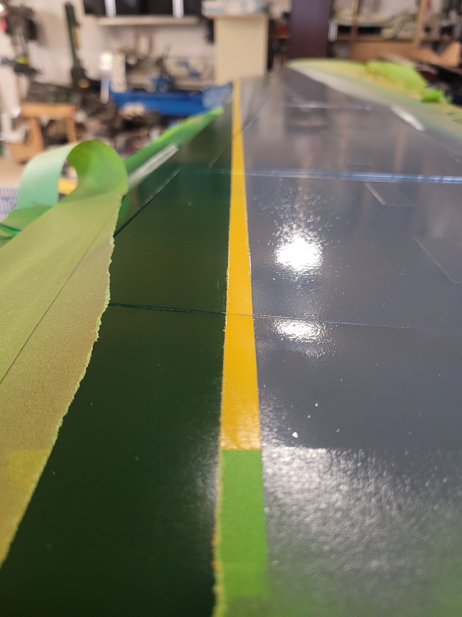
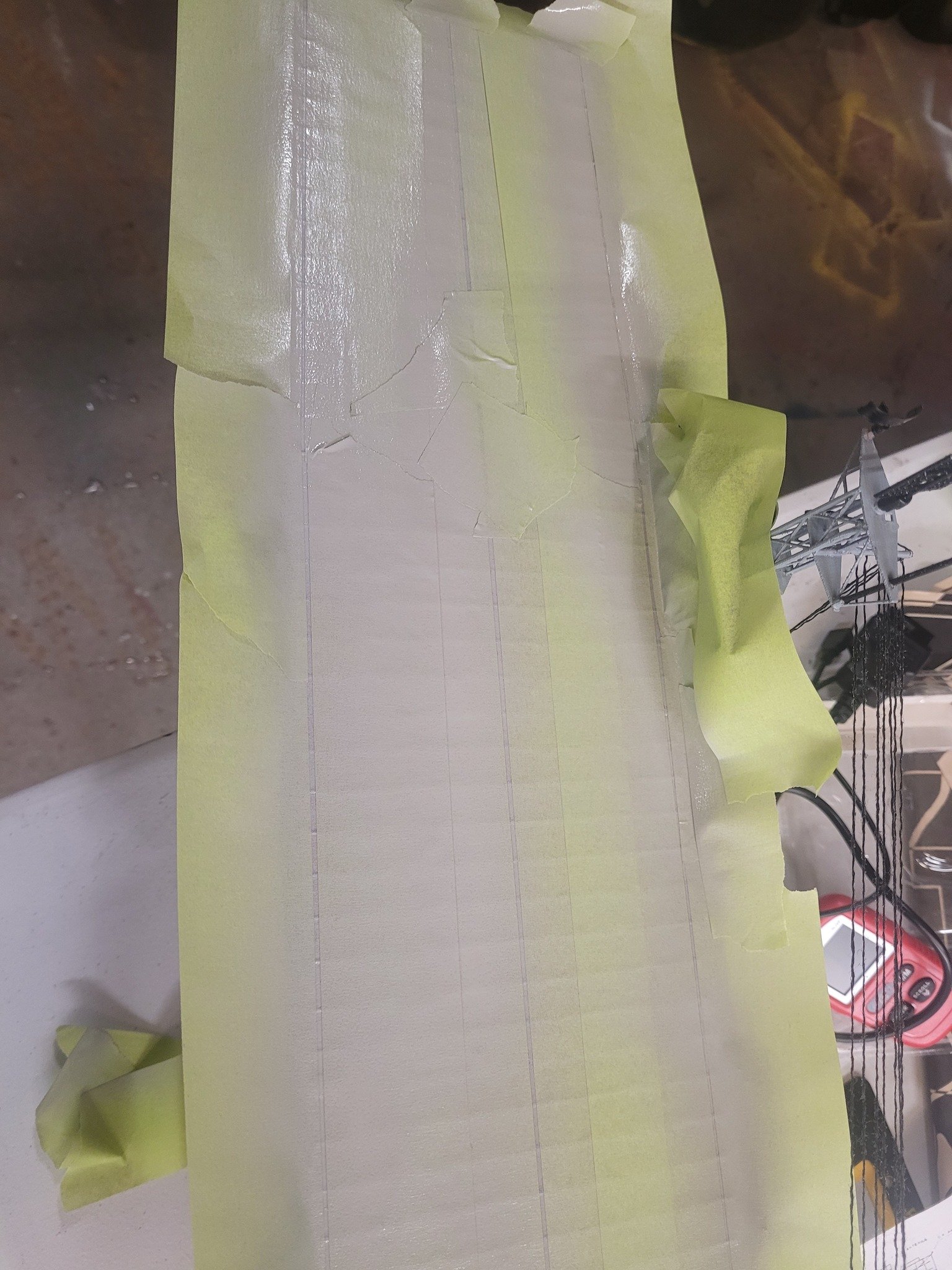
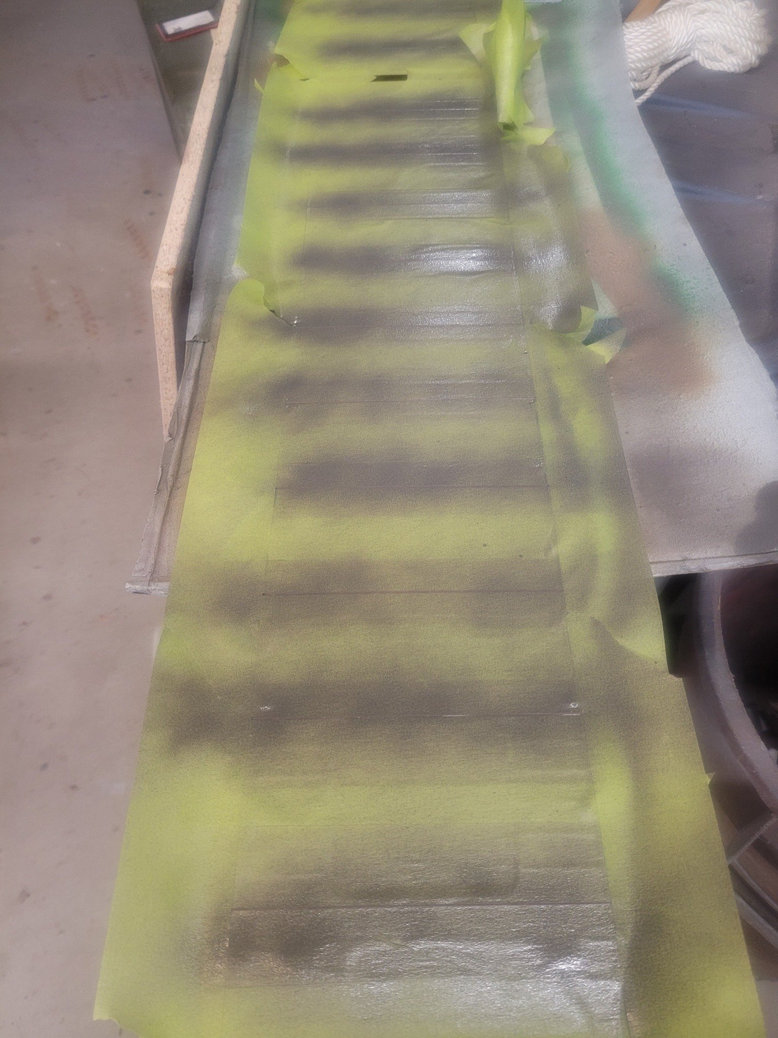
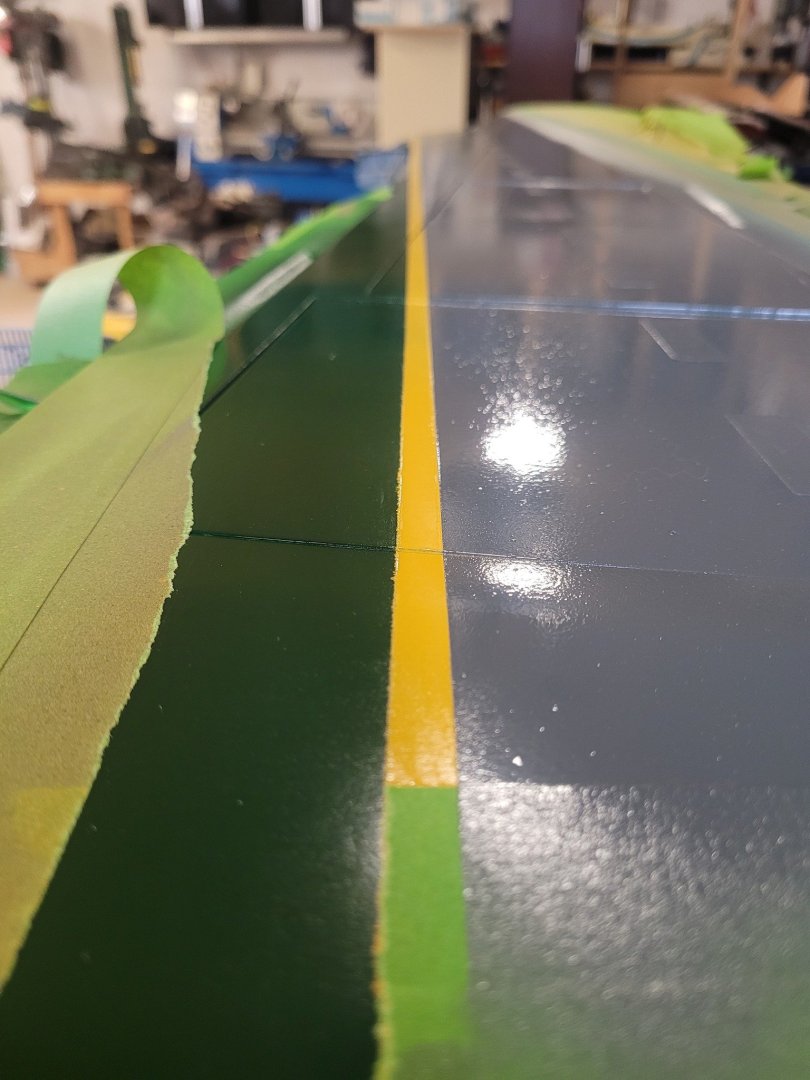
 Pulling the masking tape off can either be so very frustrating, or so very satisfying. I am quite satisfied with this outcome. Time to add decals.
-
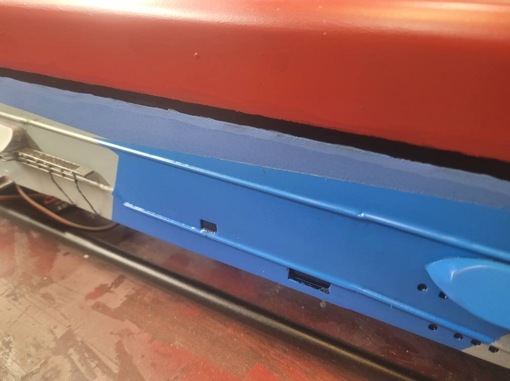
I'm a sailor....everything should be Ship's Side Gray....thanks for staying on point and identifying the flaws!
-
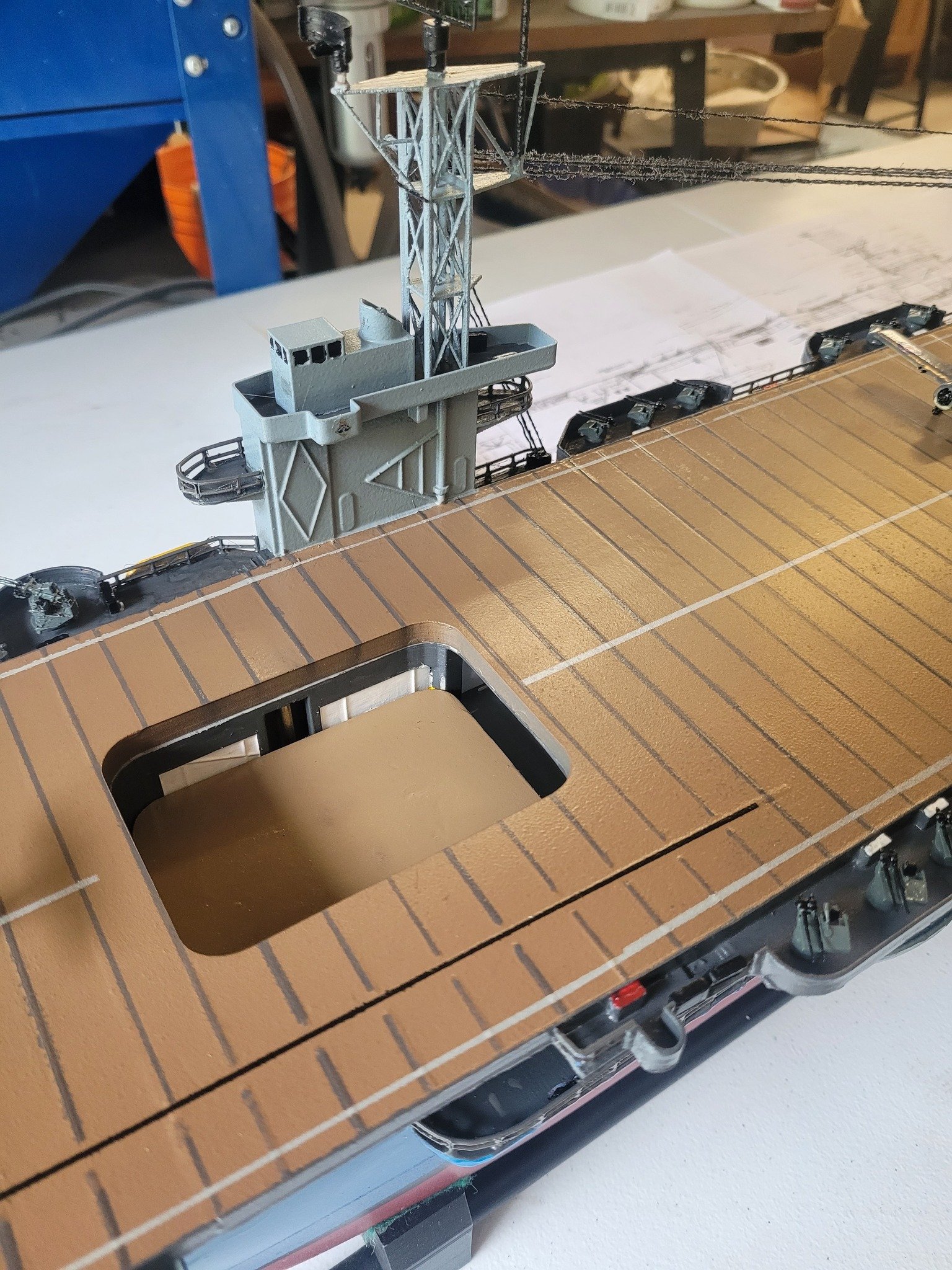
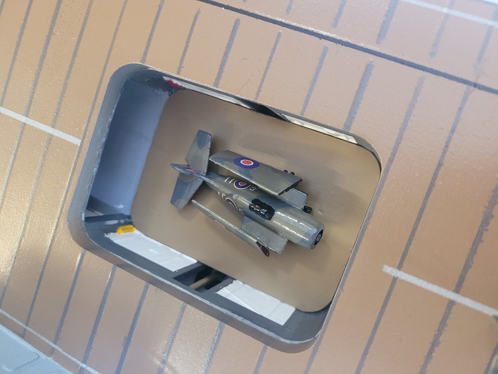
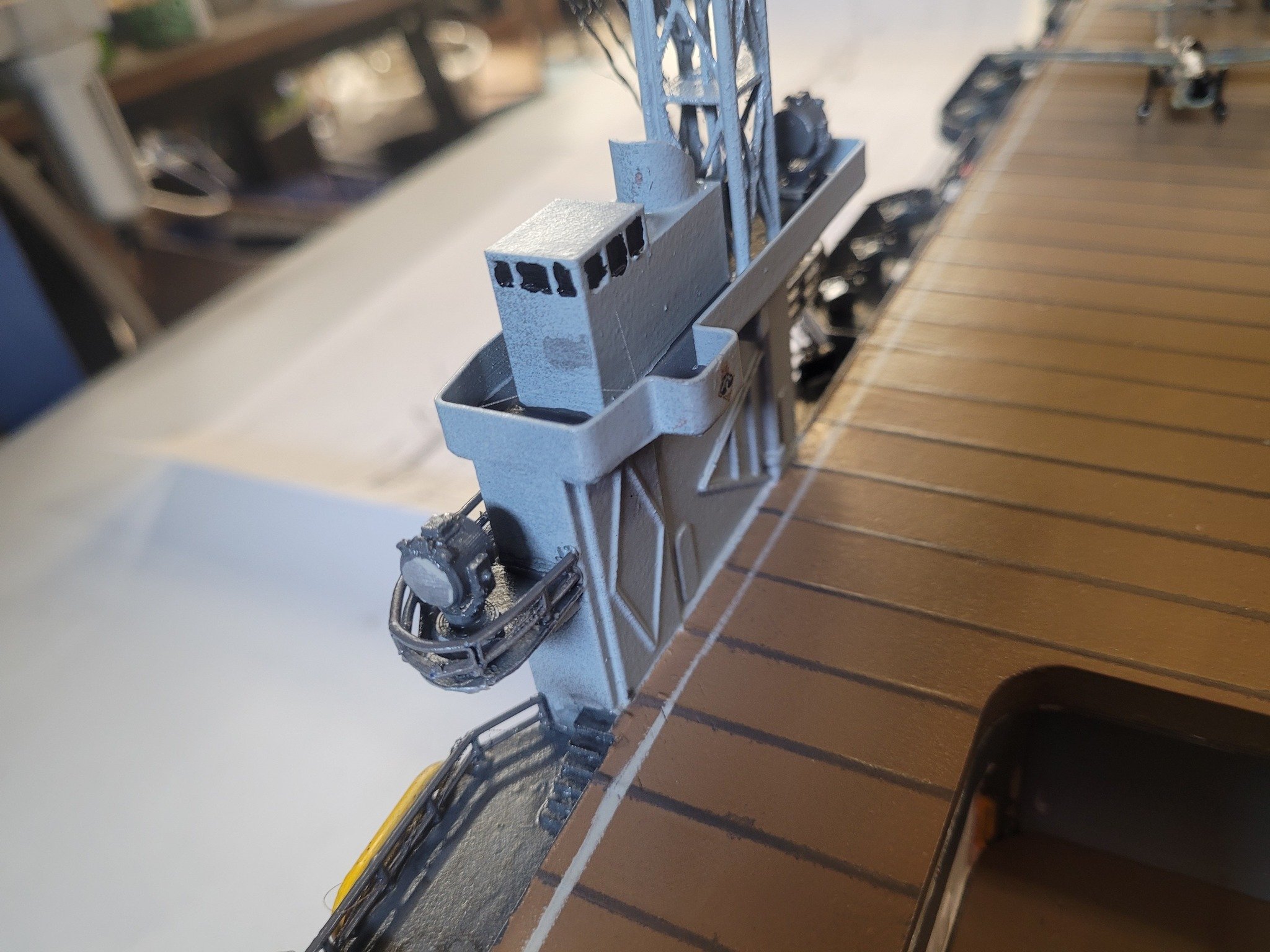
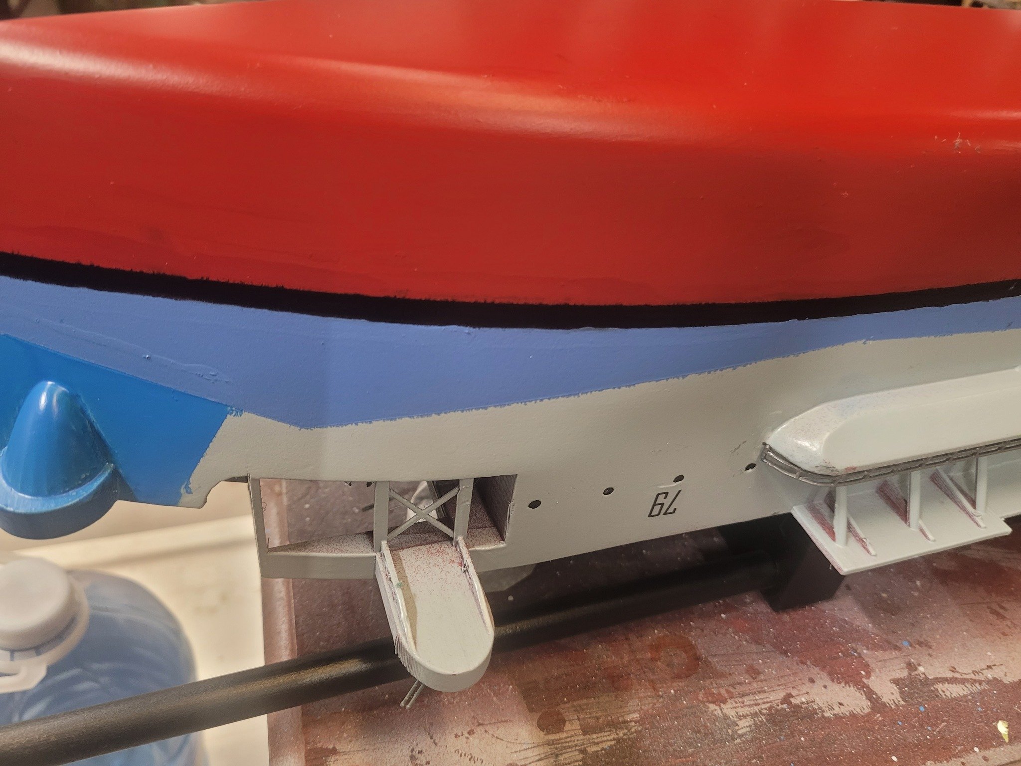
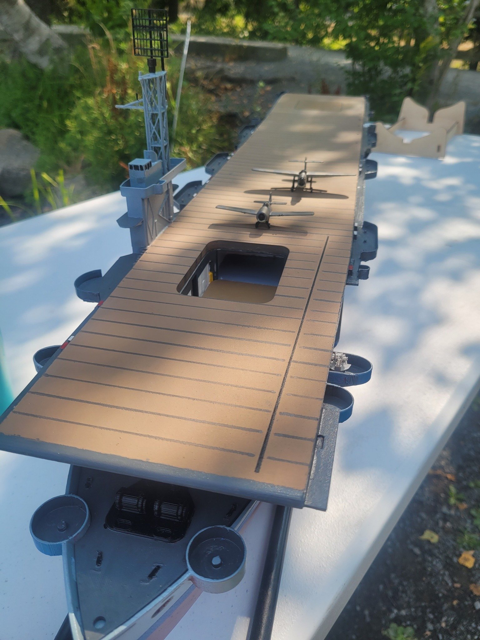
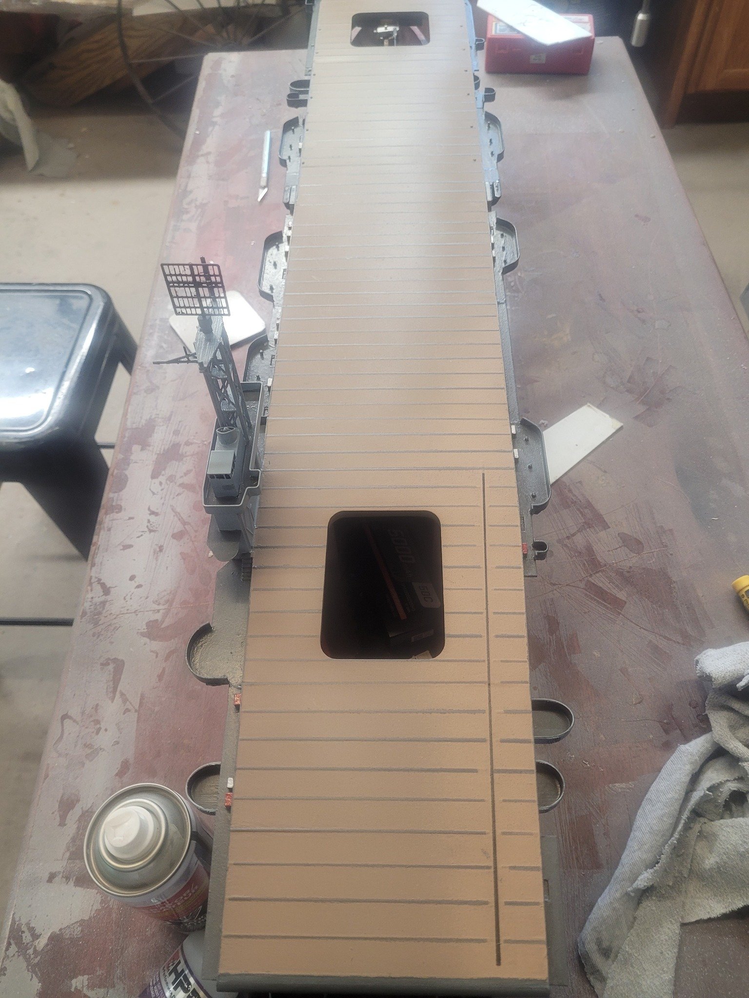
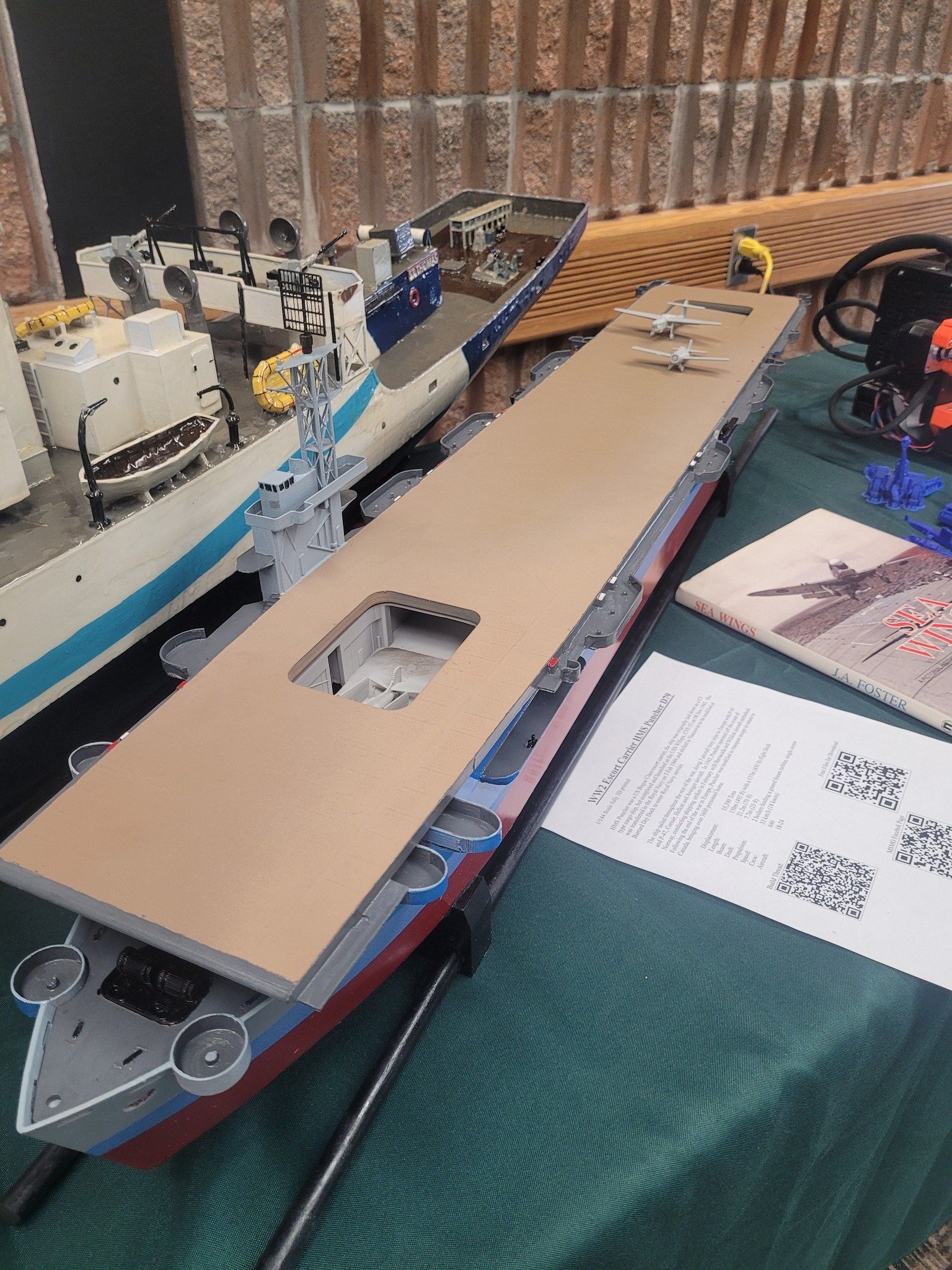
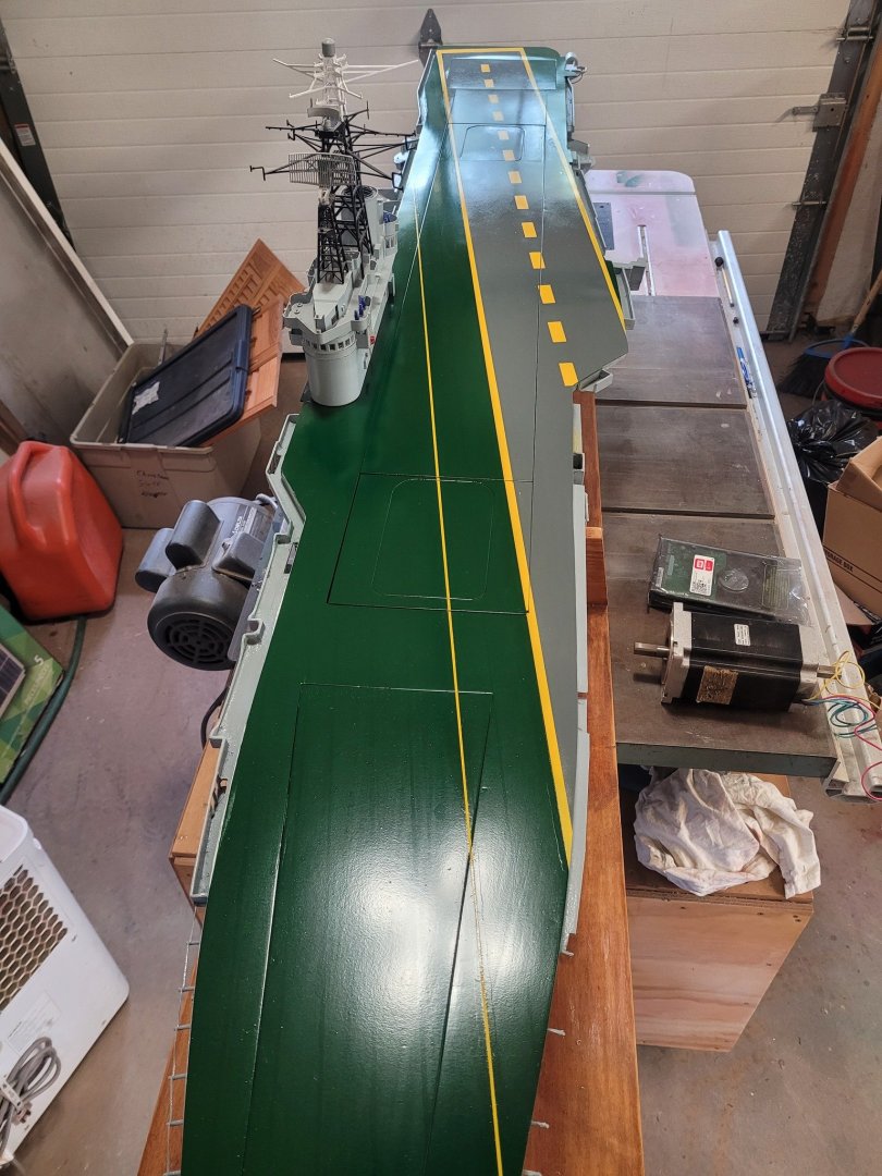
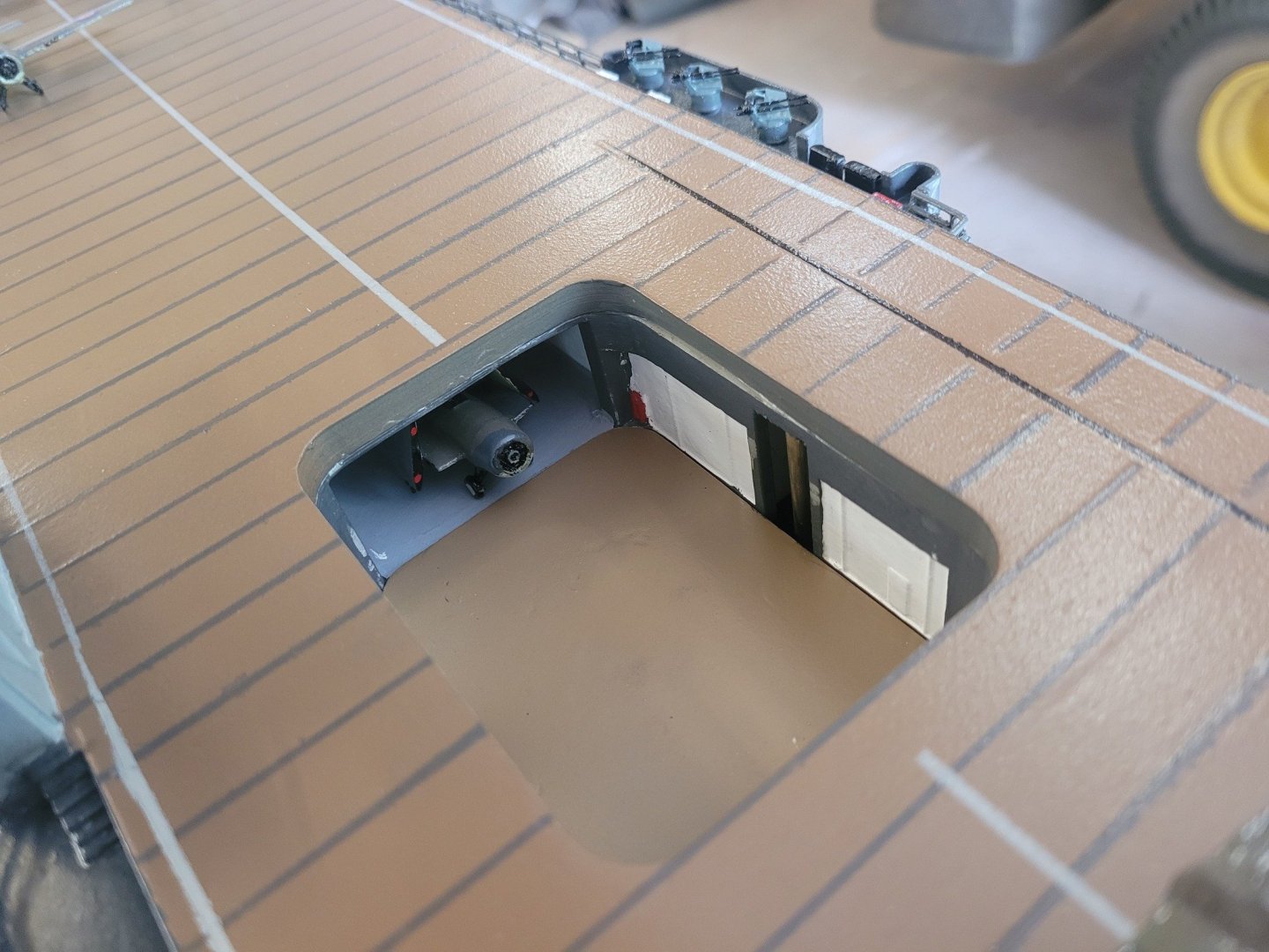
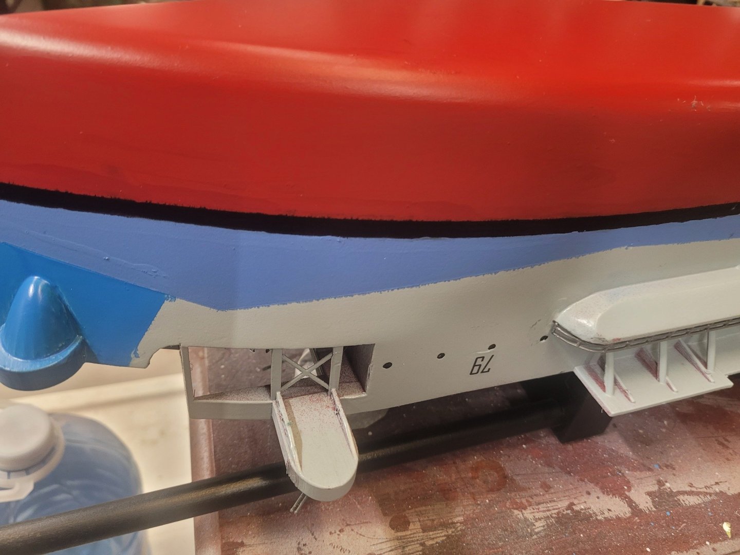
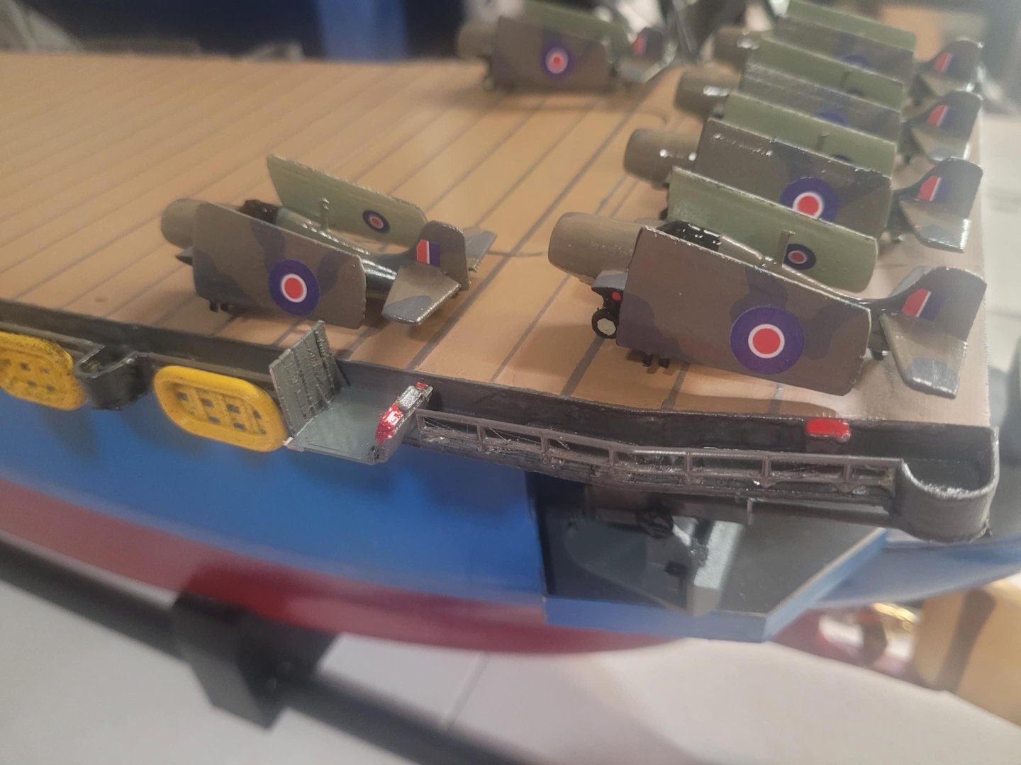
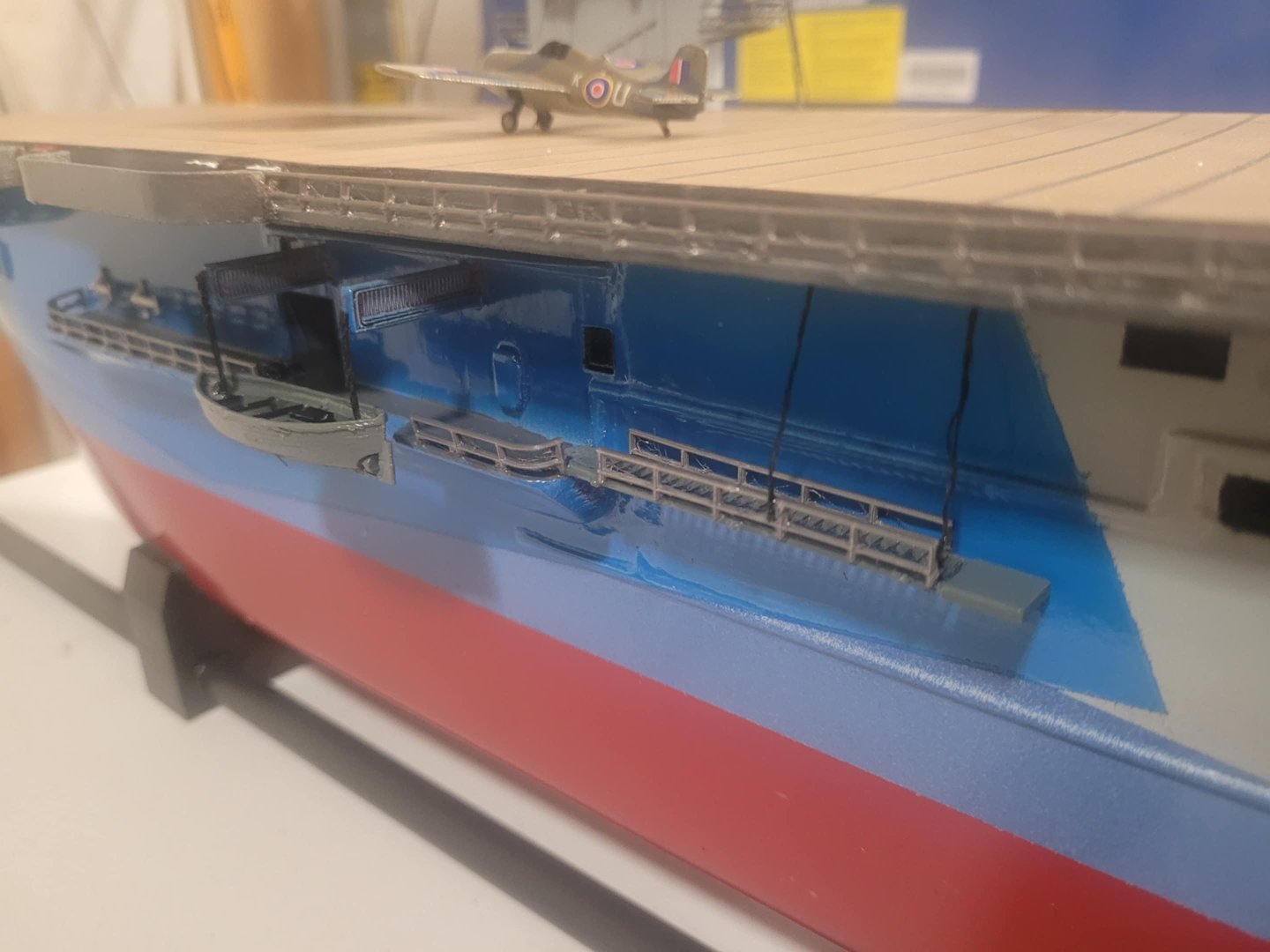
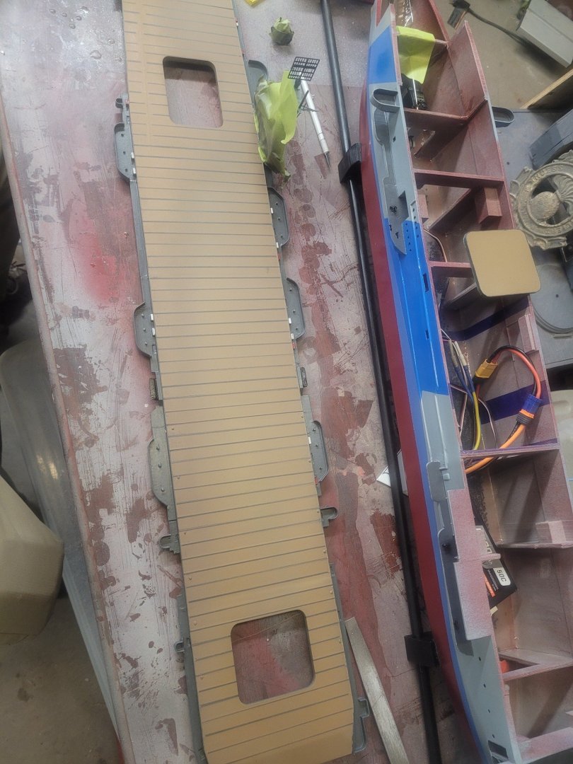
Well, tidying up some minor issues on the flight deck starting with the round-down. Then because I had some overspray into the hangar, I had to tidy that up. Hangar has also had some stiffening members added across the top - I'm pleased with how things look!


-
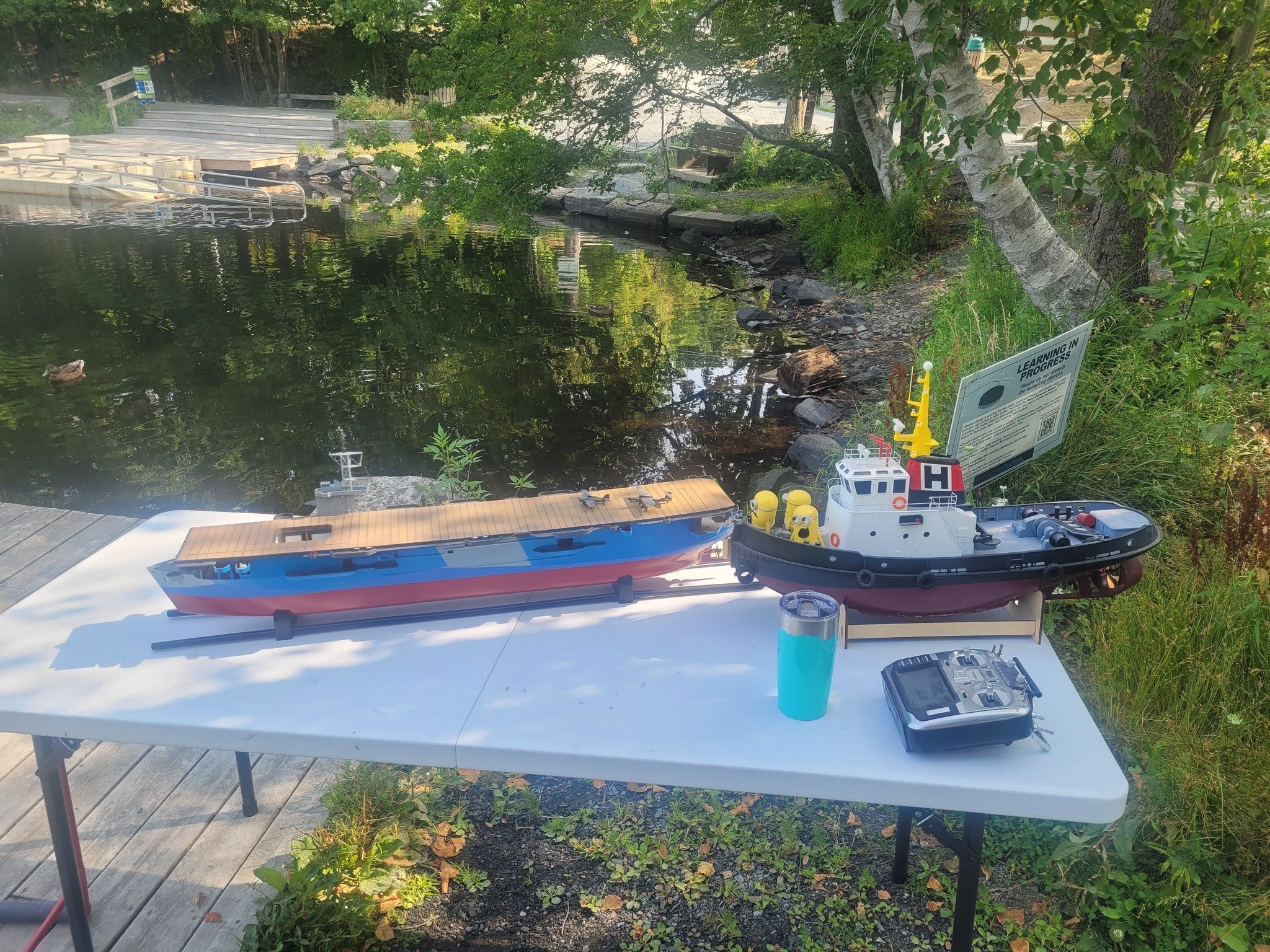
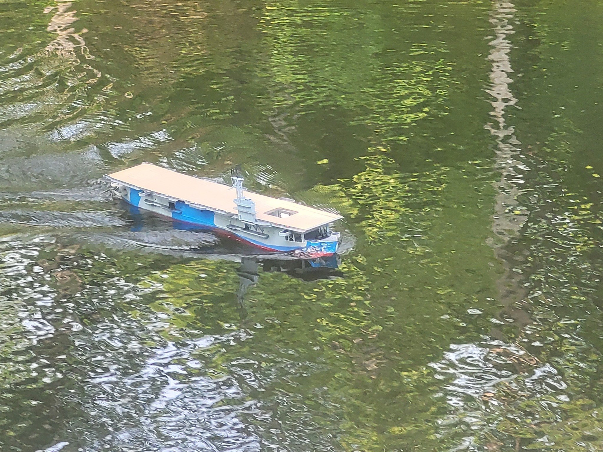
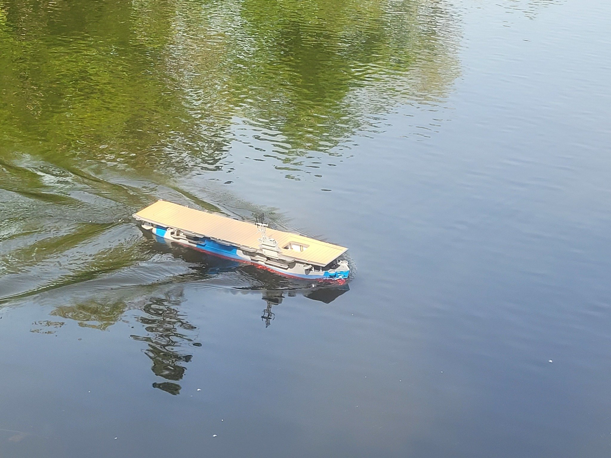
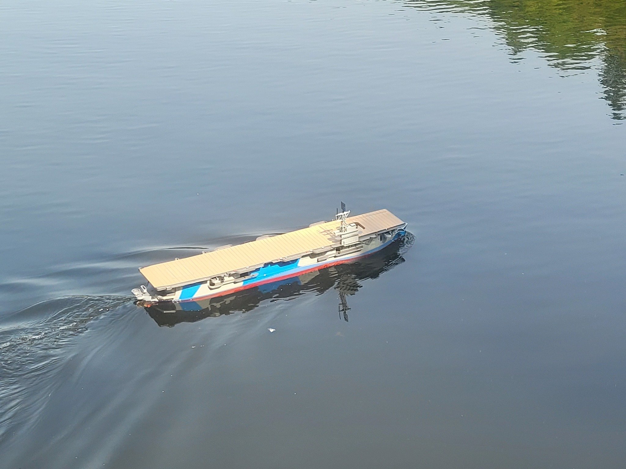
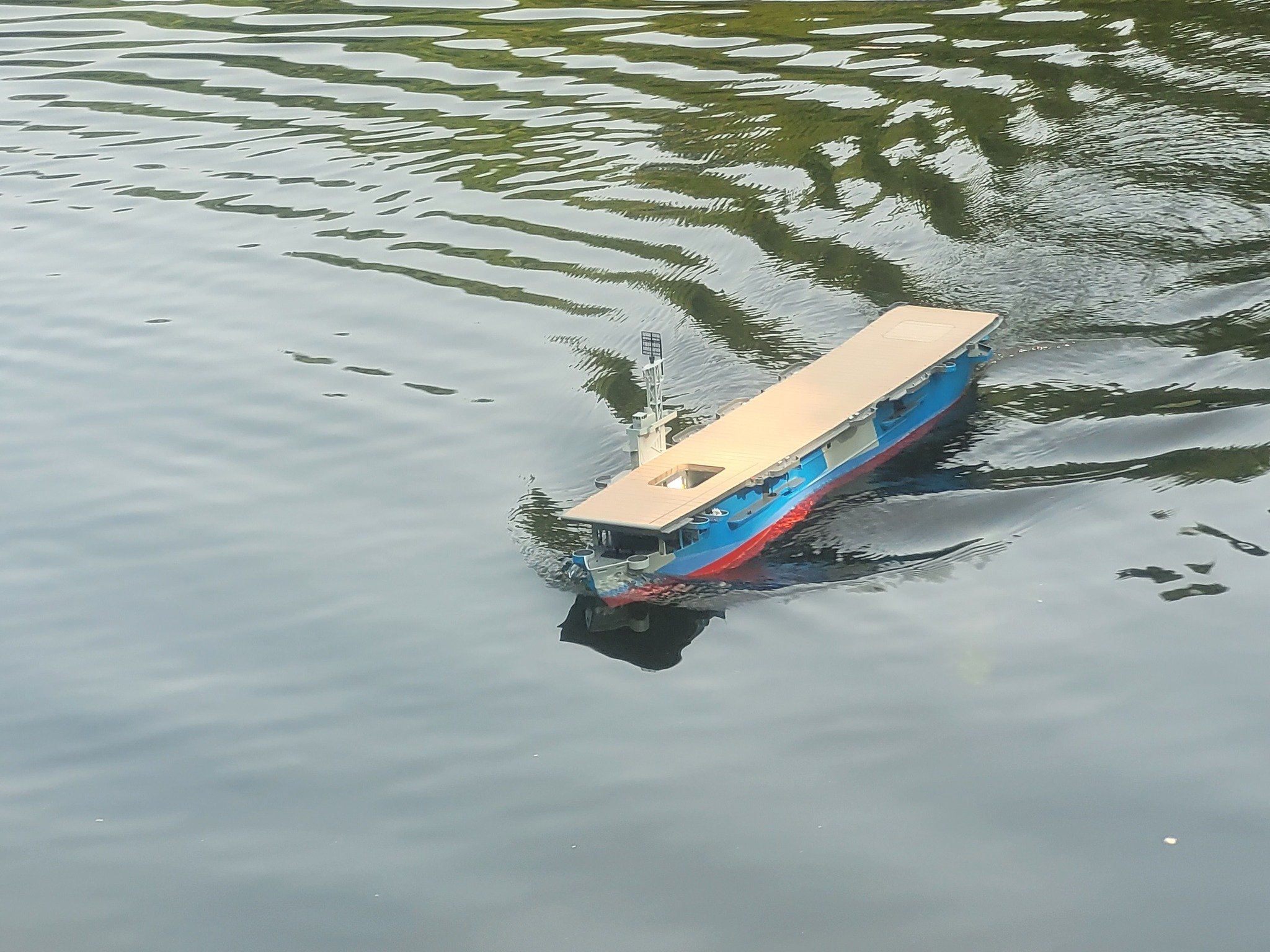
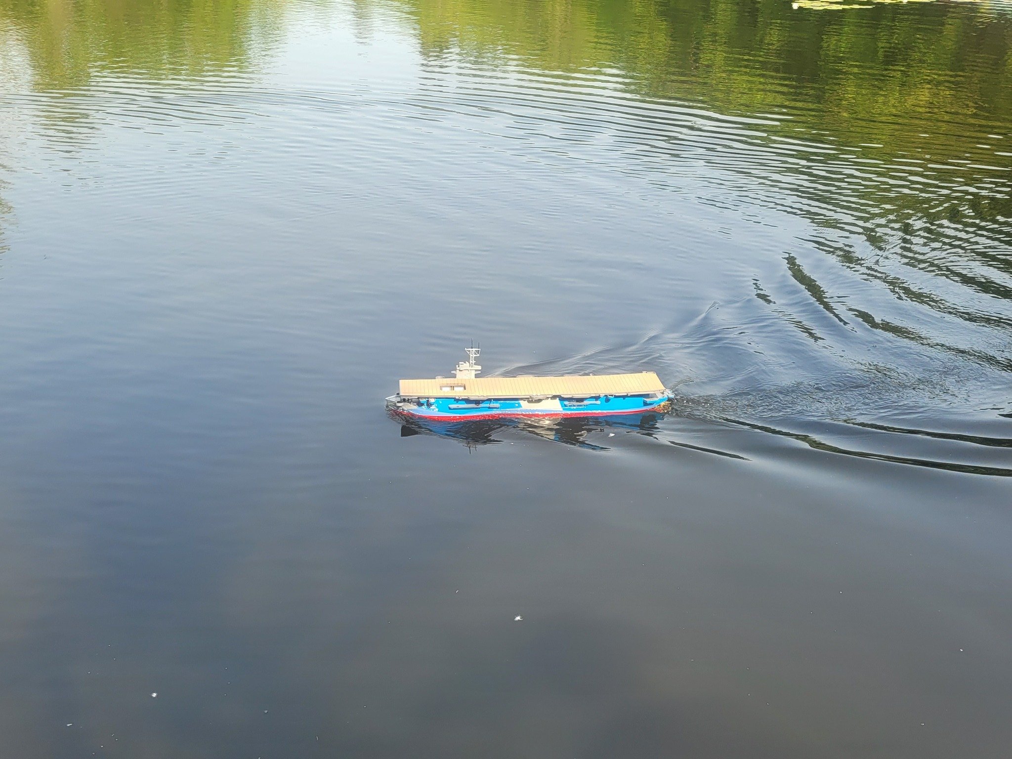
My thanks! The rudder is about 200% oversize so that she'll actually perform decently in the pond. In fact, because of the size of the rudder, it actually acts as something of a speed-brake when she's hard over. I'm pleased with the mix of detail and the durability of this build. Interestingly, there's over 120 people world-wide that have downloaded the free 3D model I shared on a couple of sites and I've been sent pictures of at least one other that's being assembled. So, net gain for the RC and model boat communities!
- 51 replies
-
- 2
-

-
- Puncher
- escort carrier
- (and 1 more)
-
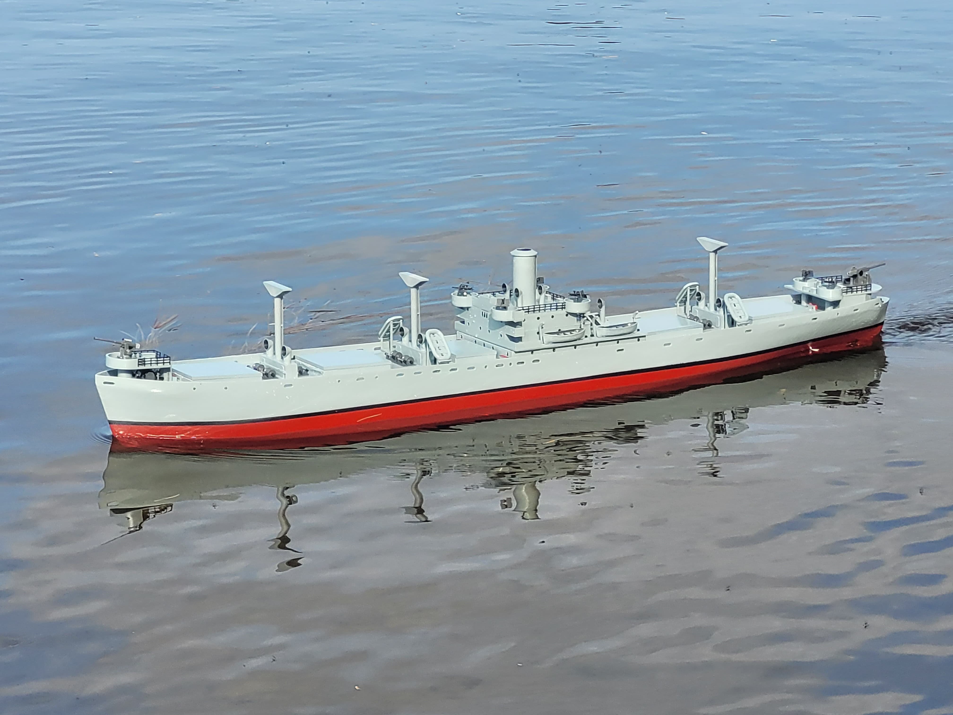
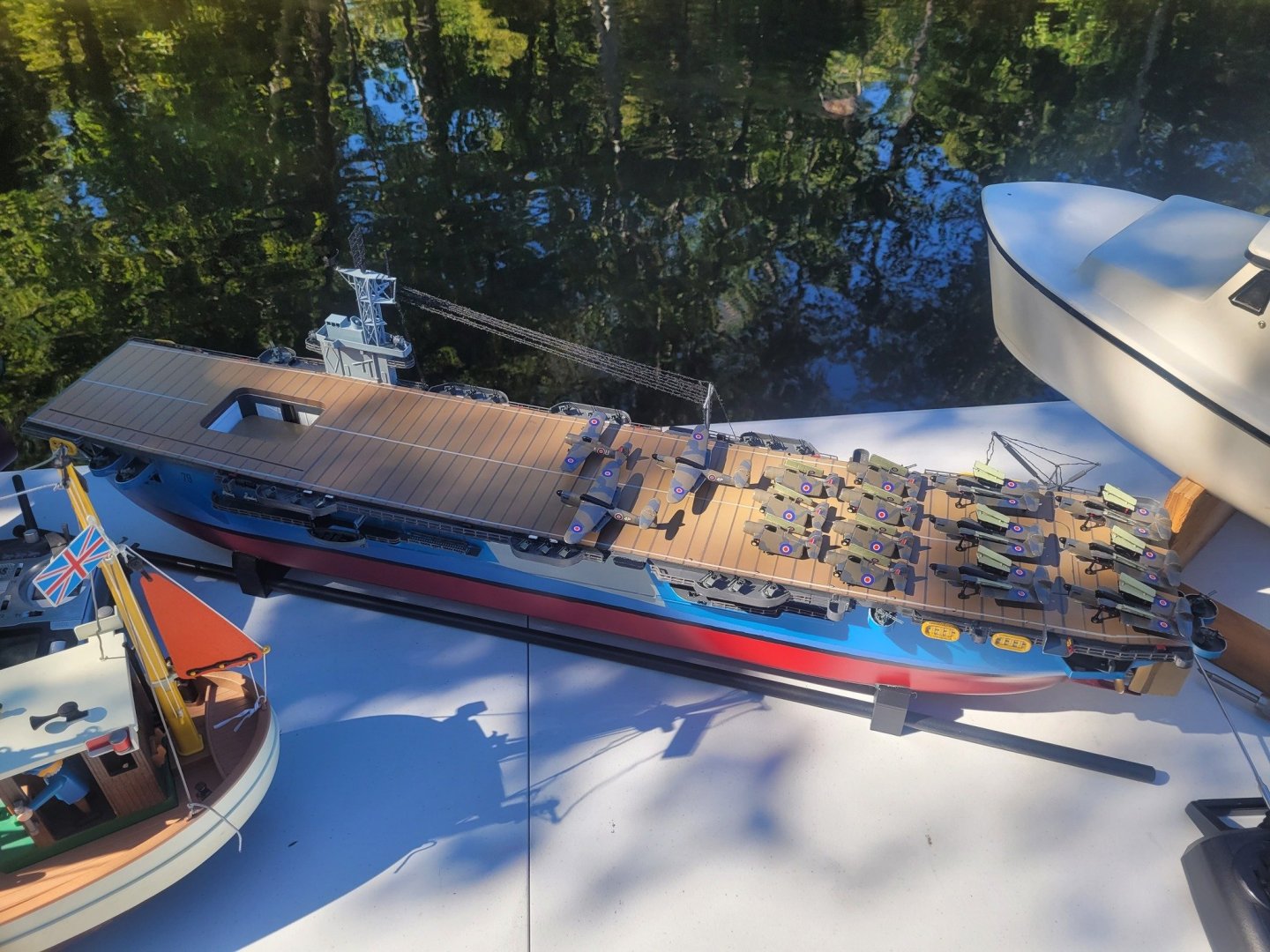
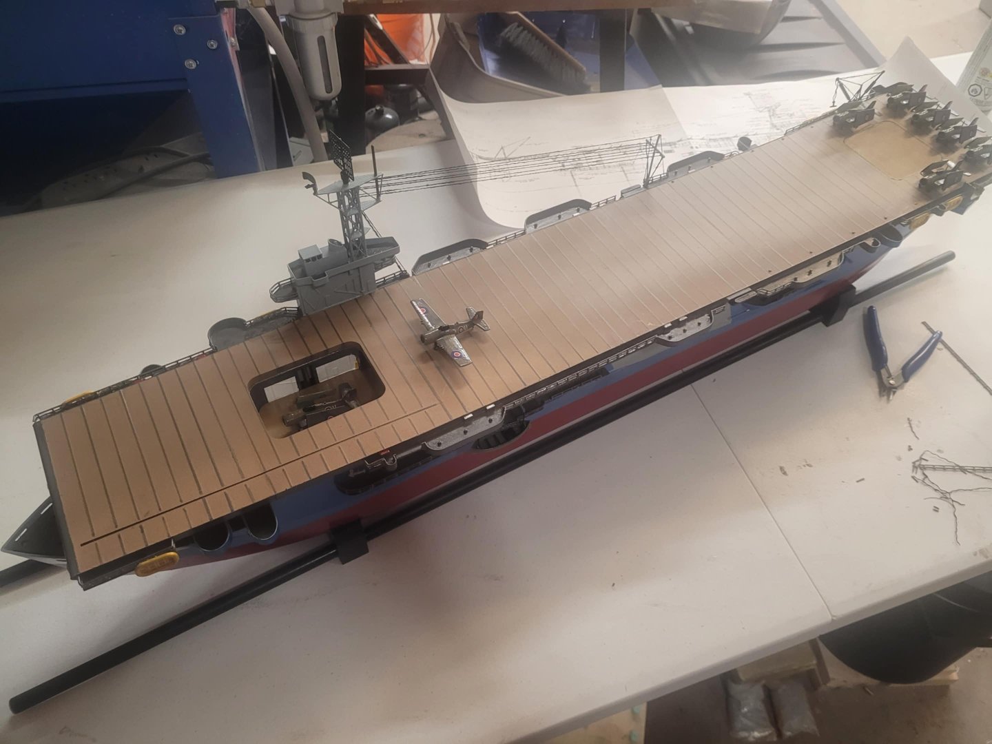
OK, I'm calling this one complete. I'm pleased with how she looks and performs - had her out at the pond on Sunday with the Guild, and all agreed that she looks pretty good. Only thing 'missing' is some signal flags. Here's the pictures - now it's back to my HMCS Bonaventure model!


- 51 replies
-
- 9
-
-
- Puncher
- escort carrier
- (and 1 more)
-
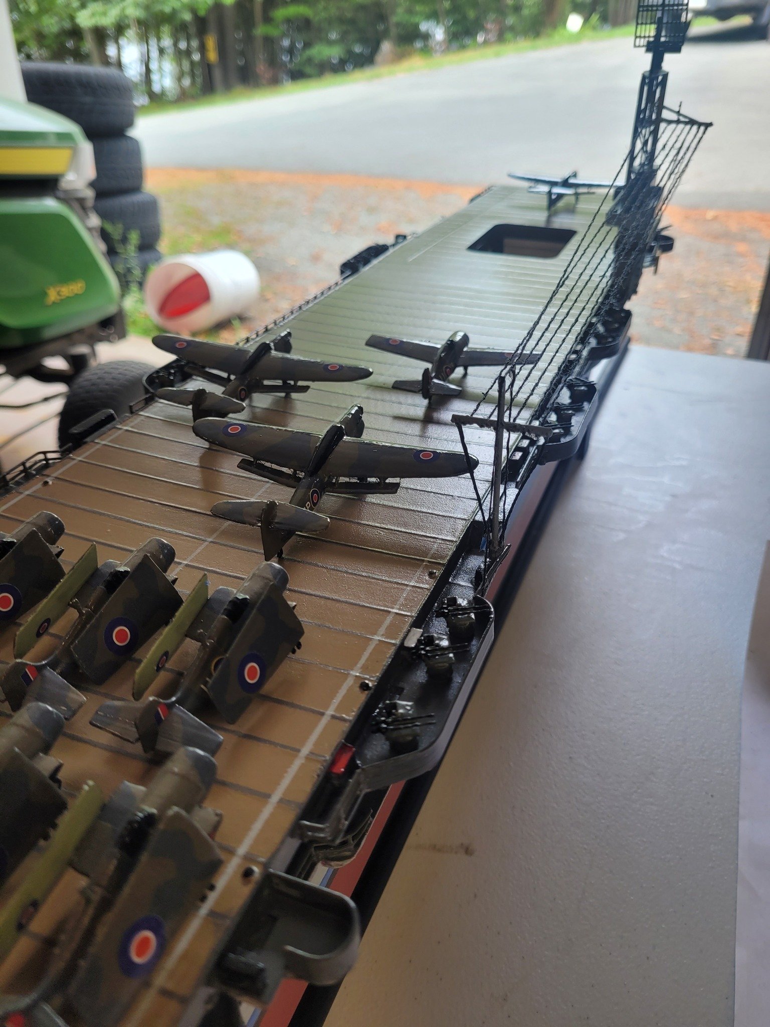
OK, boot topping is fixed enough....and the Barracudas are done. All that's left on my 'to do' list is to secure the flight deck better to the hull, make some search lights, and add some flags.
- 51 replies
-
- 5
-
-
- Puncher
- escort carrier
- (and 1 more)
-
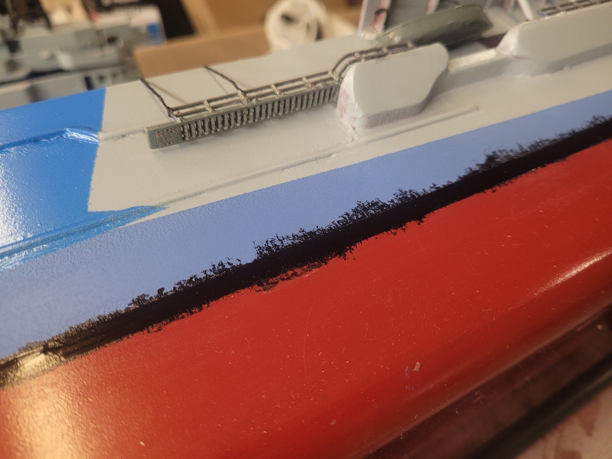
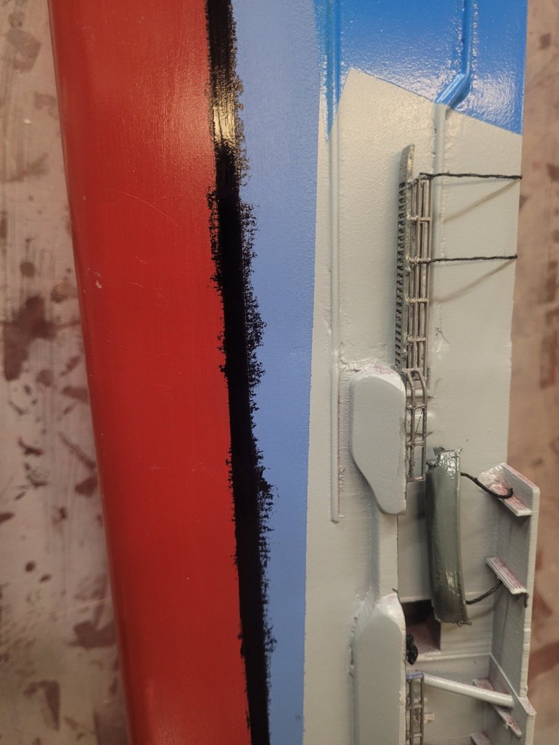
I touched up the bleeding last night, and decided to hand-paint the other side of the hull. Looks OK. I guess. I'm going to get some matt clear coat tonight and spray the hull with that to seal it in and maybe the matt will blend the hand-painted touch-ups a bit.
- 51 replies
-
- 1
-
-
- Puncher
- escort carrier
- (and 1 more)
-
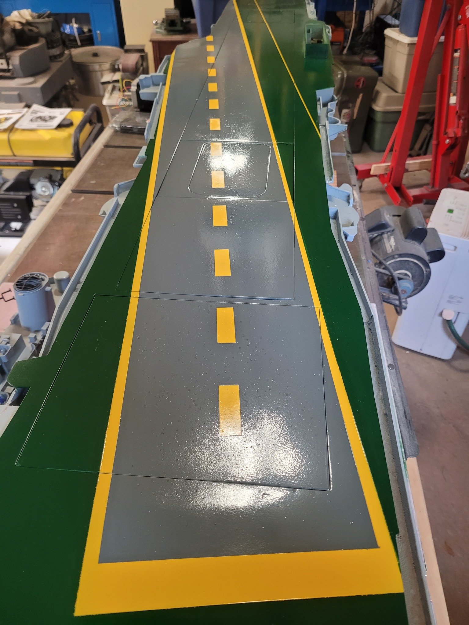
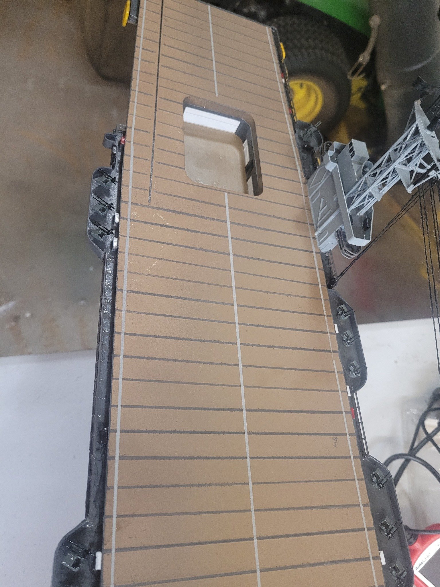
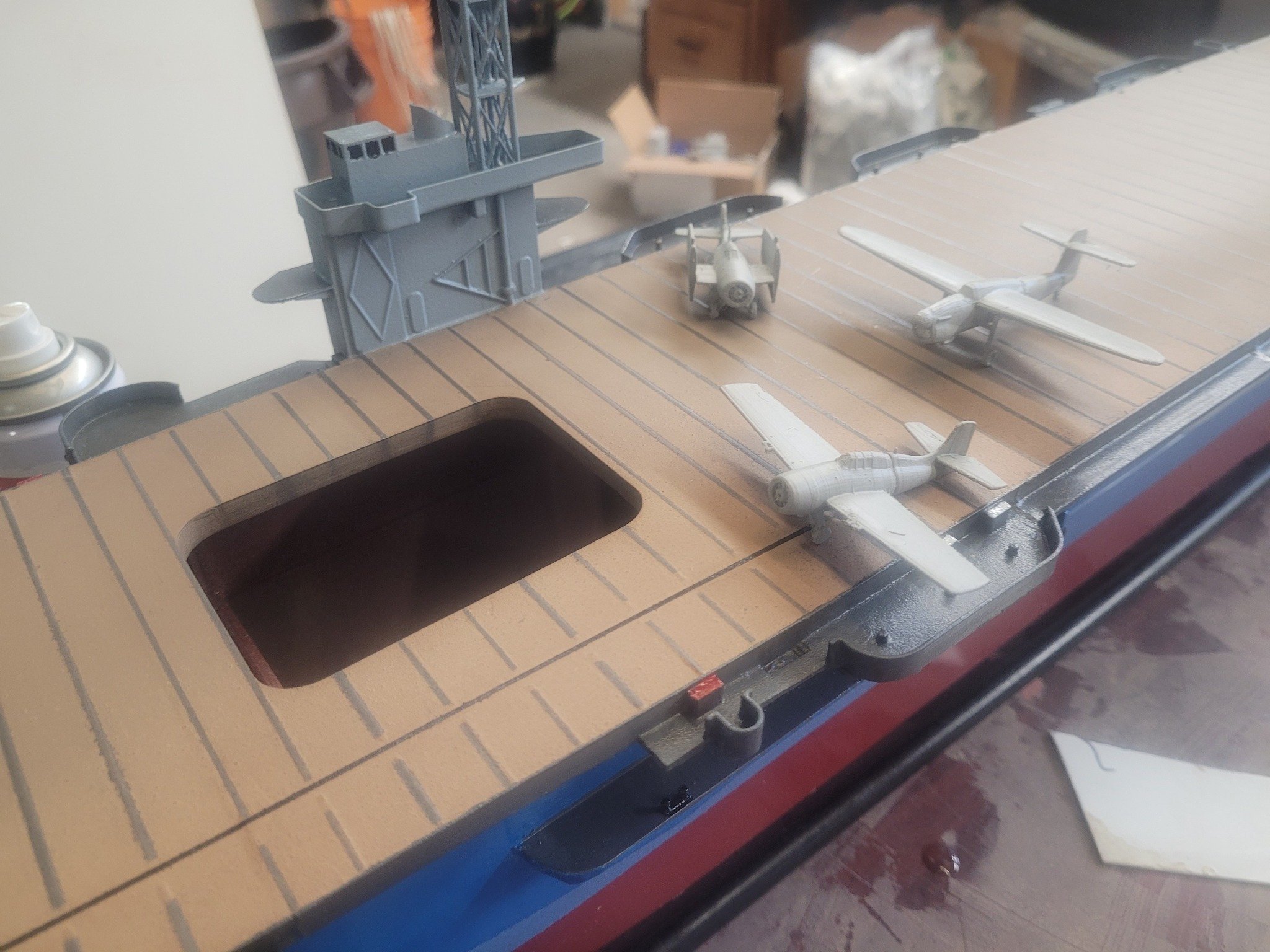
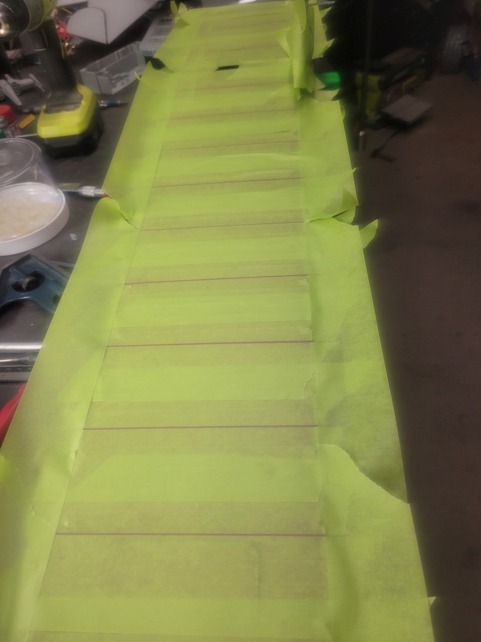
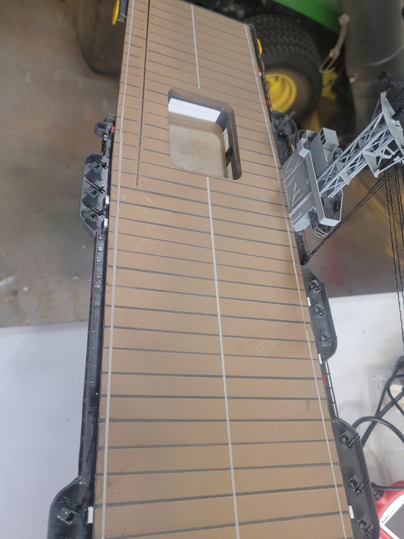
I also realized that I needed to add lines (white/gray) along the centerline and deck edges on the flight deck. This DID go well.

- 51 replies
-
- 3
-
-
- Puncher
- escort carrier
- (and 1 more)
-
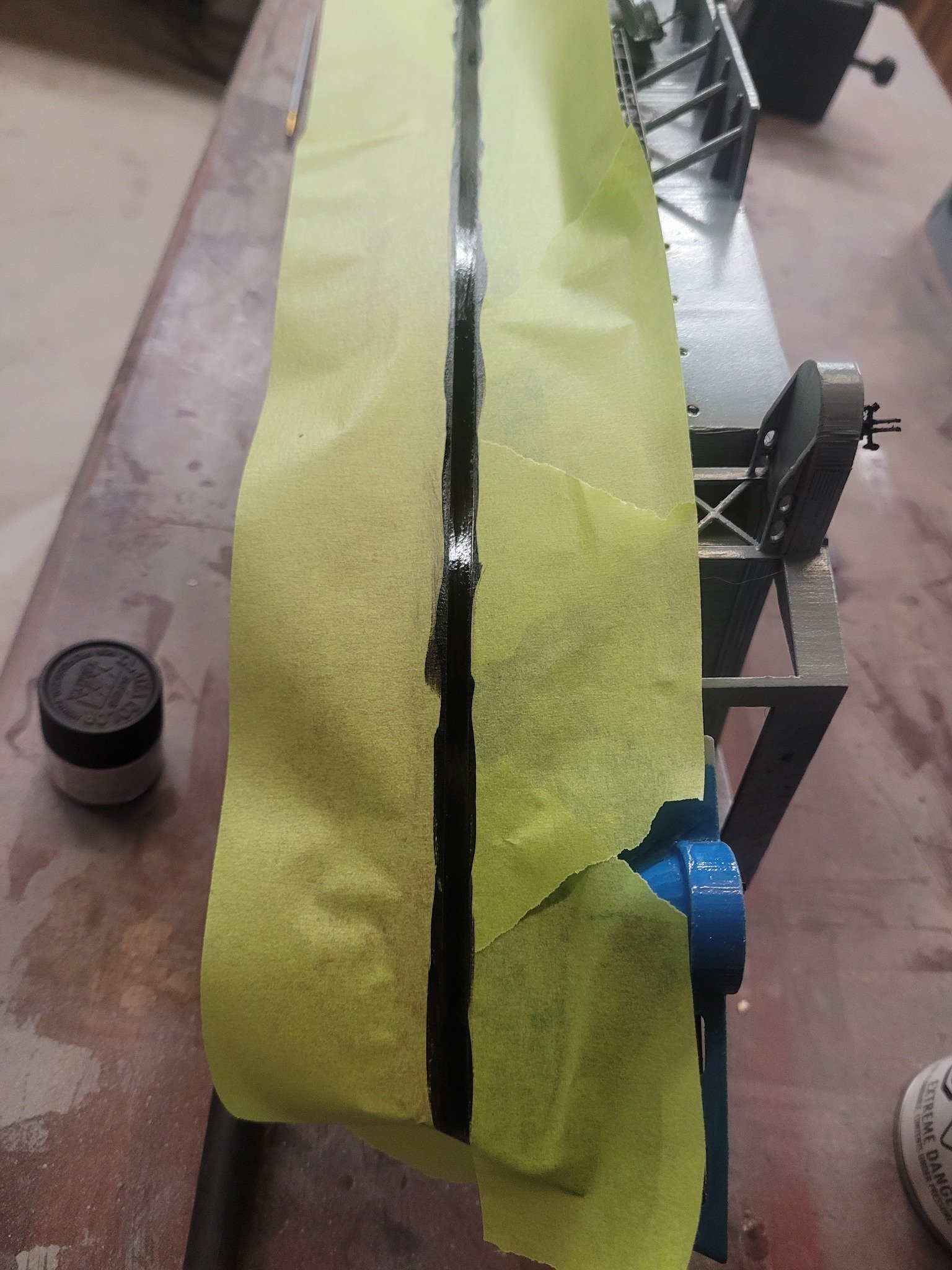
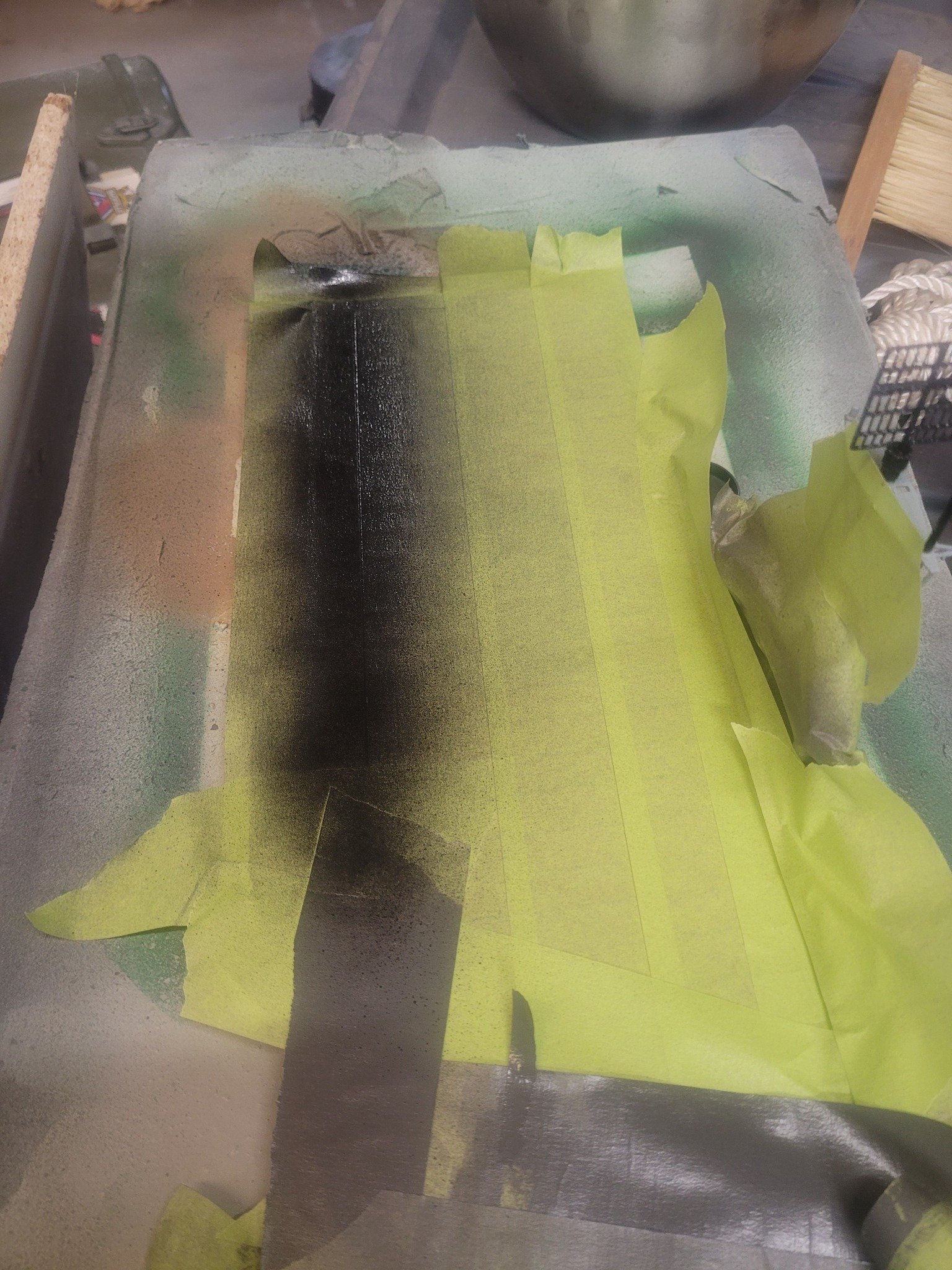
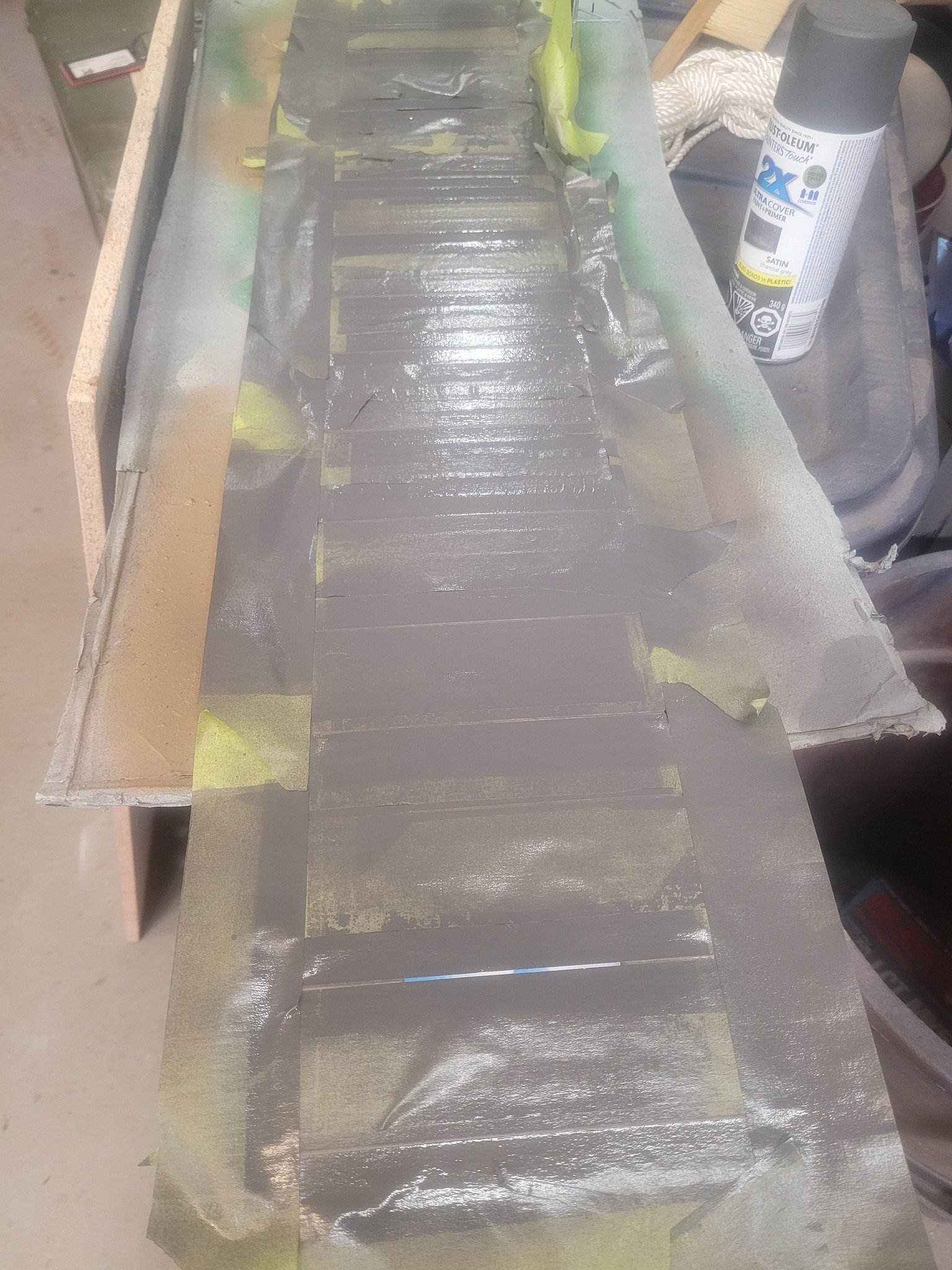
I decided to do the boot topping tonight. This did not go well.


- 51 replies
-
- 3
-
-
- Puncher
- escort carrier
- (and 1 more)
-
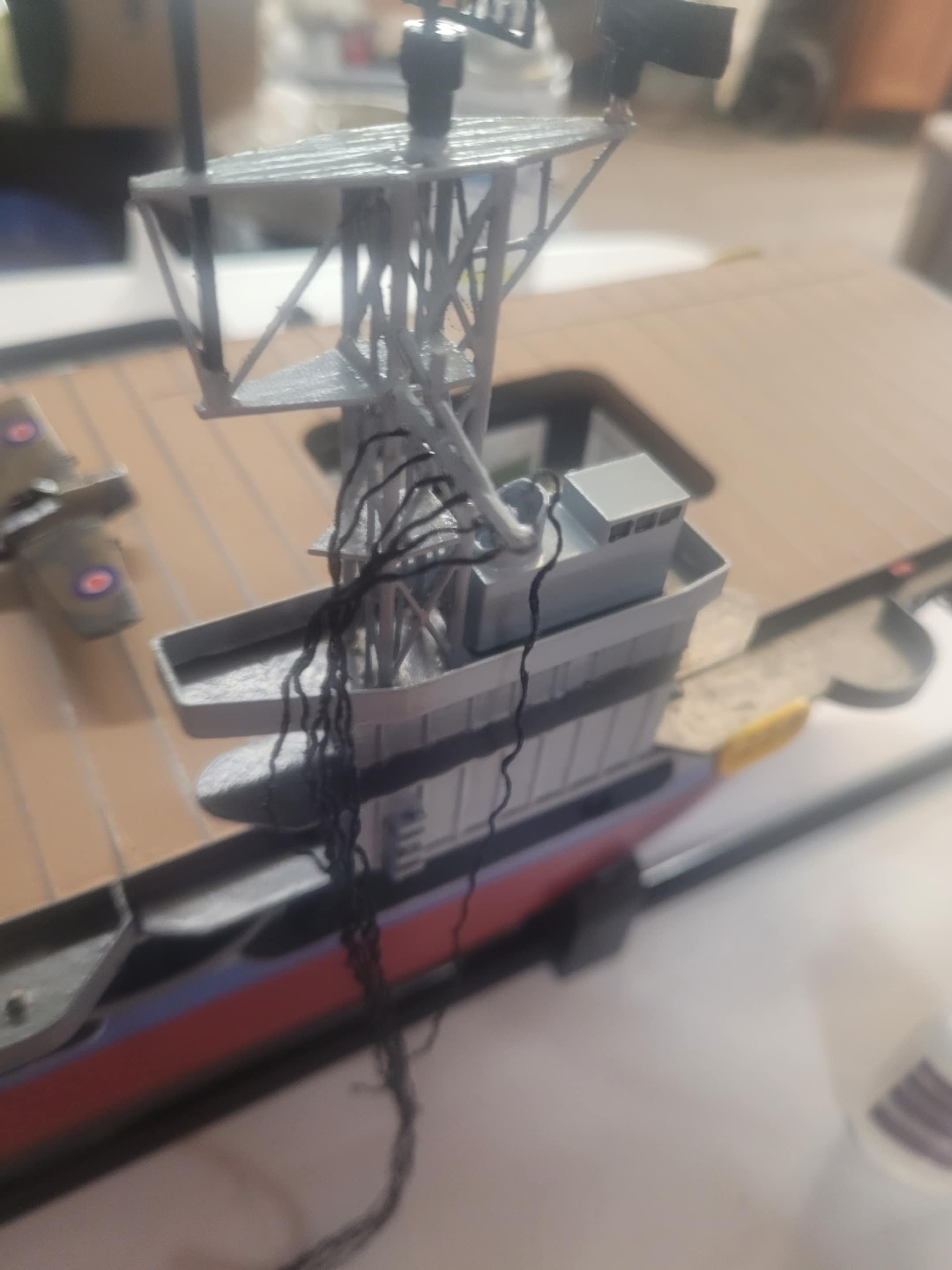
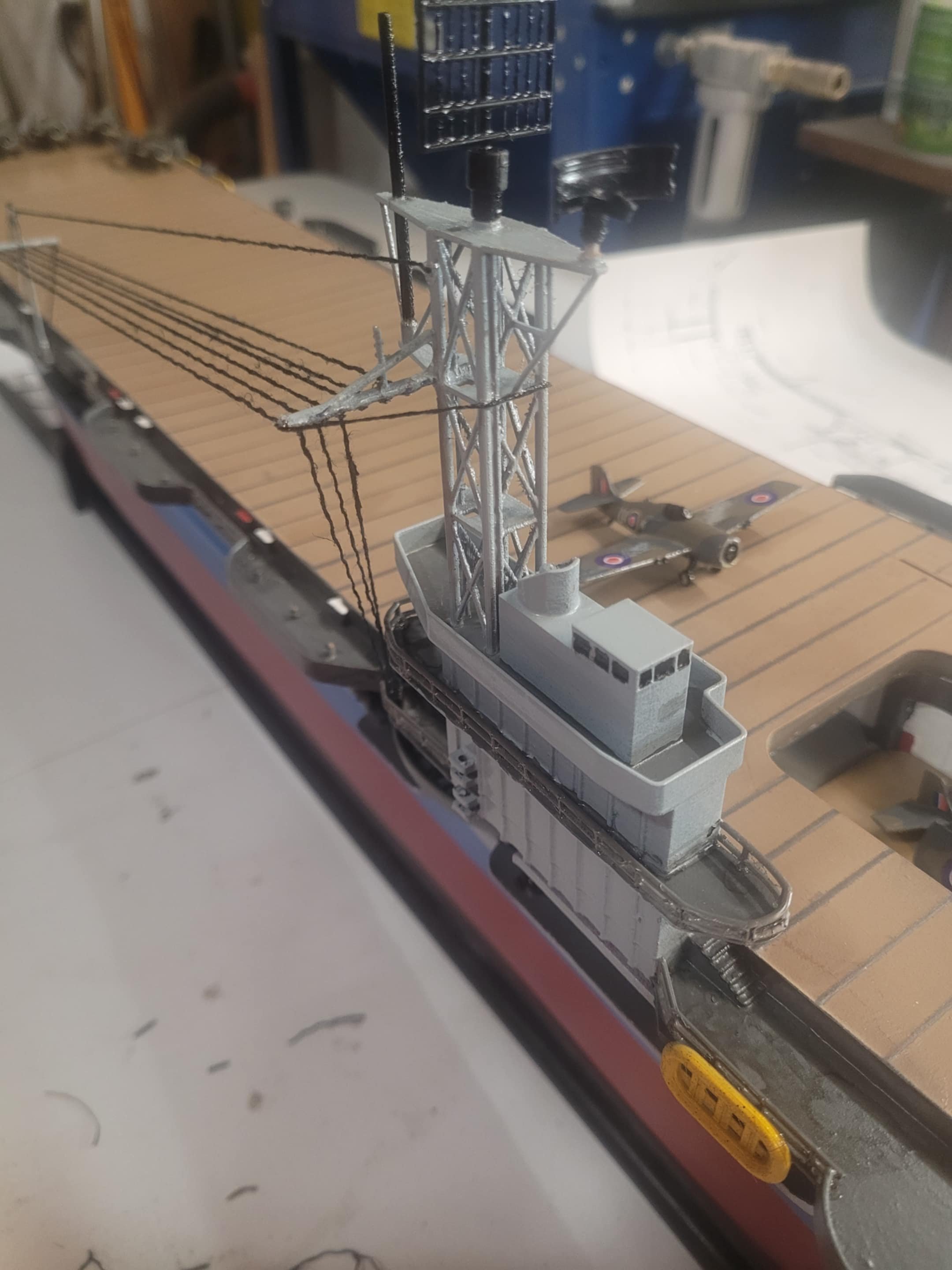
I decided to glue in some basic rigging tonight, then, because I had printed and painted them, I did the guard-rails. My 'To do" list is getting short: 20mm guns paint/install 40mm guns paint/install Barracuda decals Barracuda wings glued on Barracuda Clear coat seal Hull markings (D79 + waterline mark + depth lines) Flags? Might want to add some signal flags too. And possibly LED lights - maybe - if I really want to do that work for a model that I'm never going to sail at night. I had to replace the rubber sleeve ball joint I was using with a proper dog-bone. Pretty much finished.


- 51 replies
-
- 4
-
-
- Puncher
- escort carrier
- (and 1 more)
-
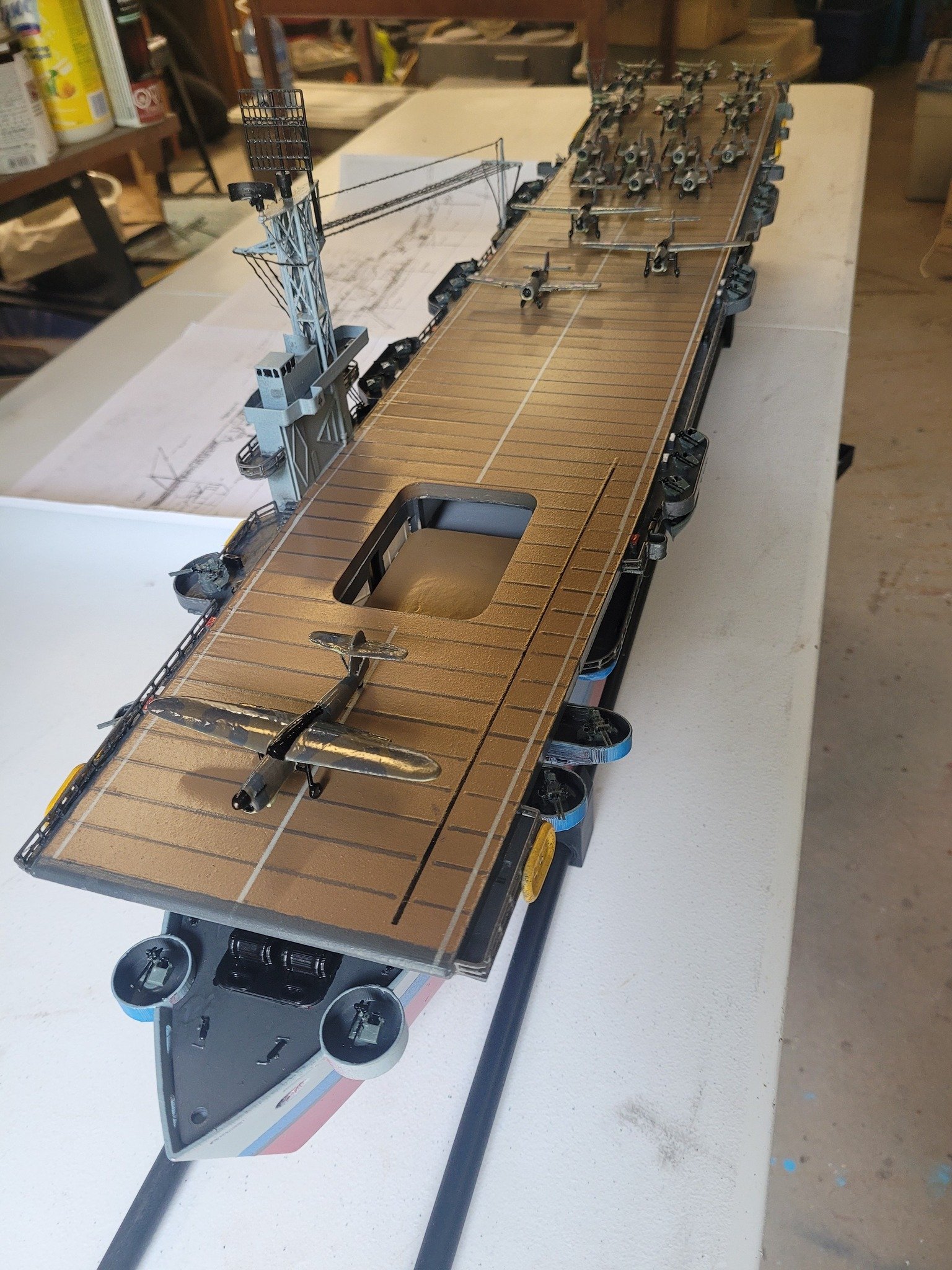
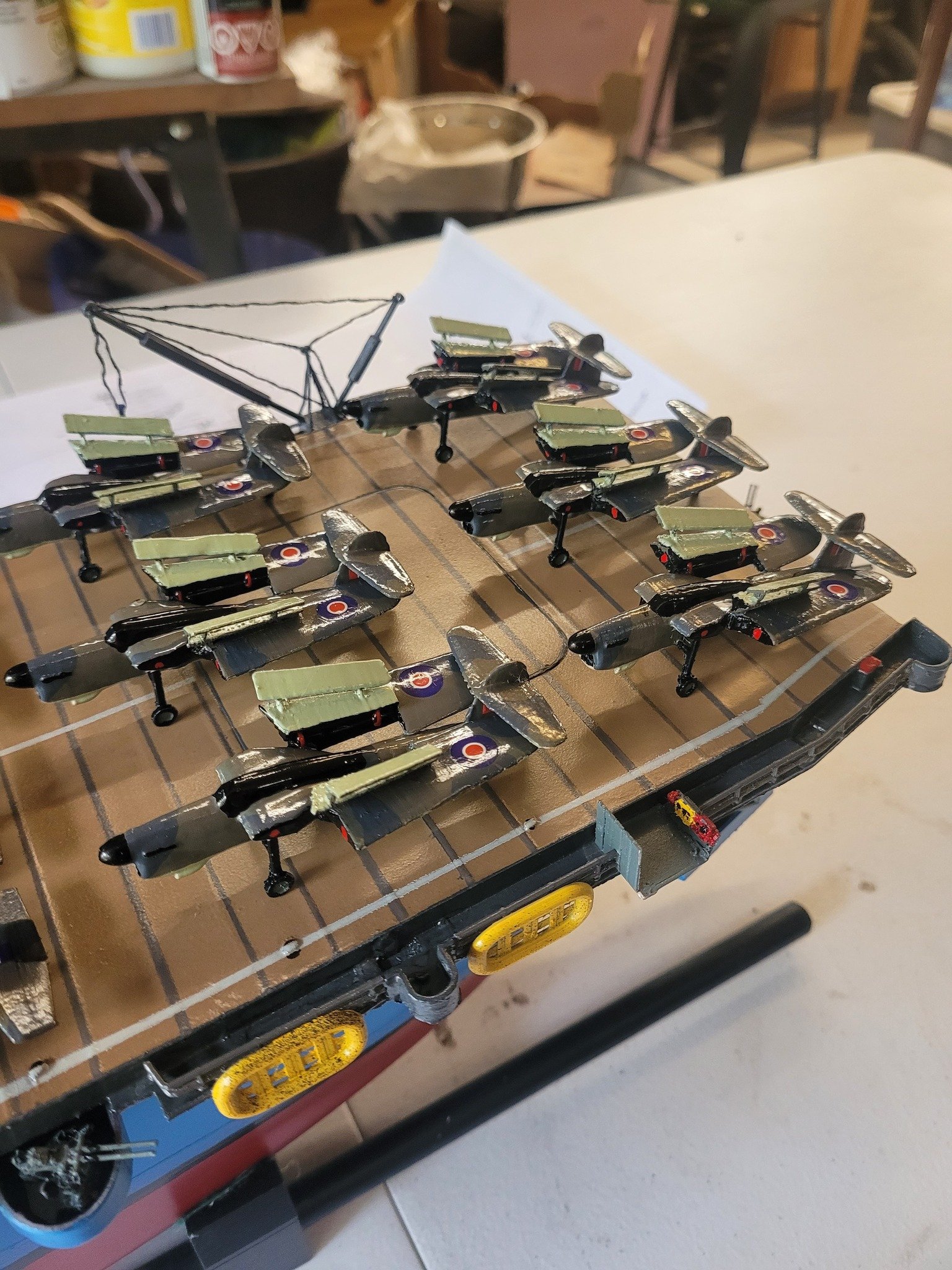
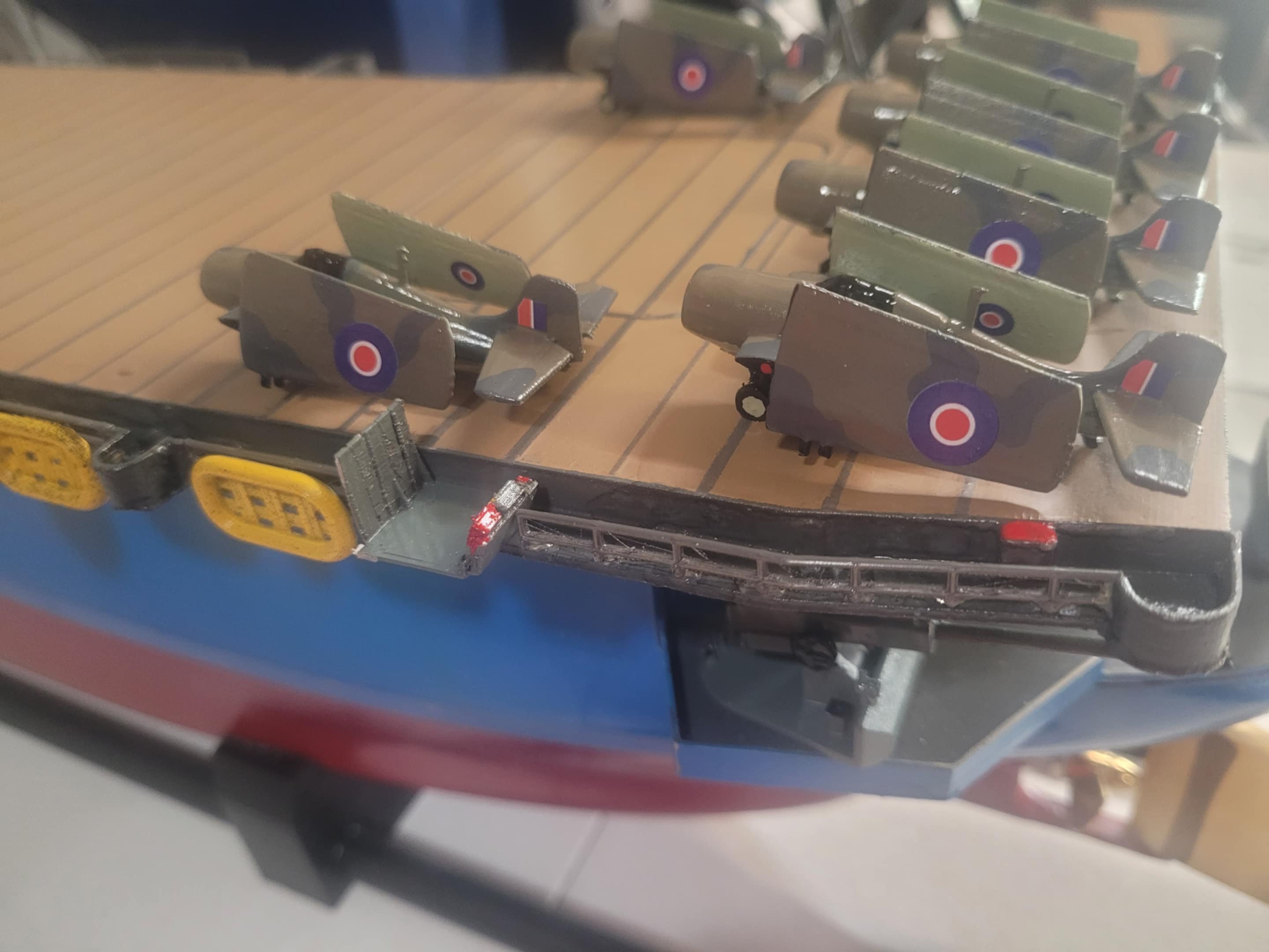
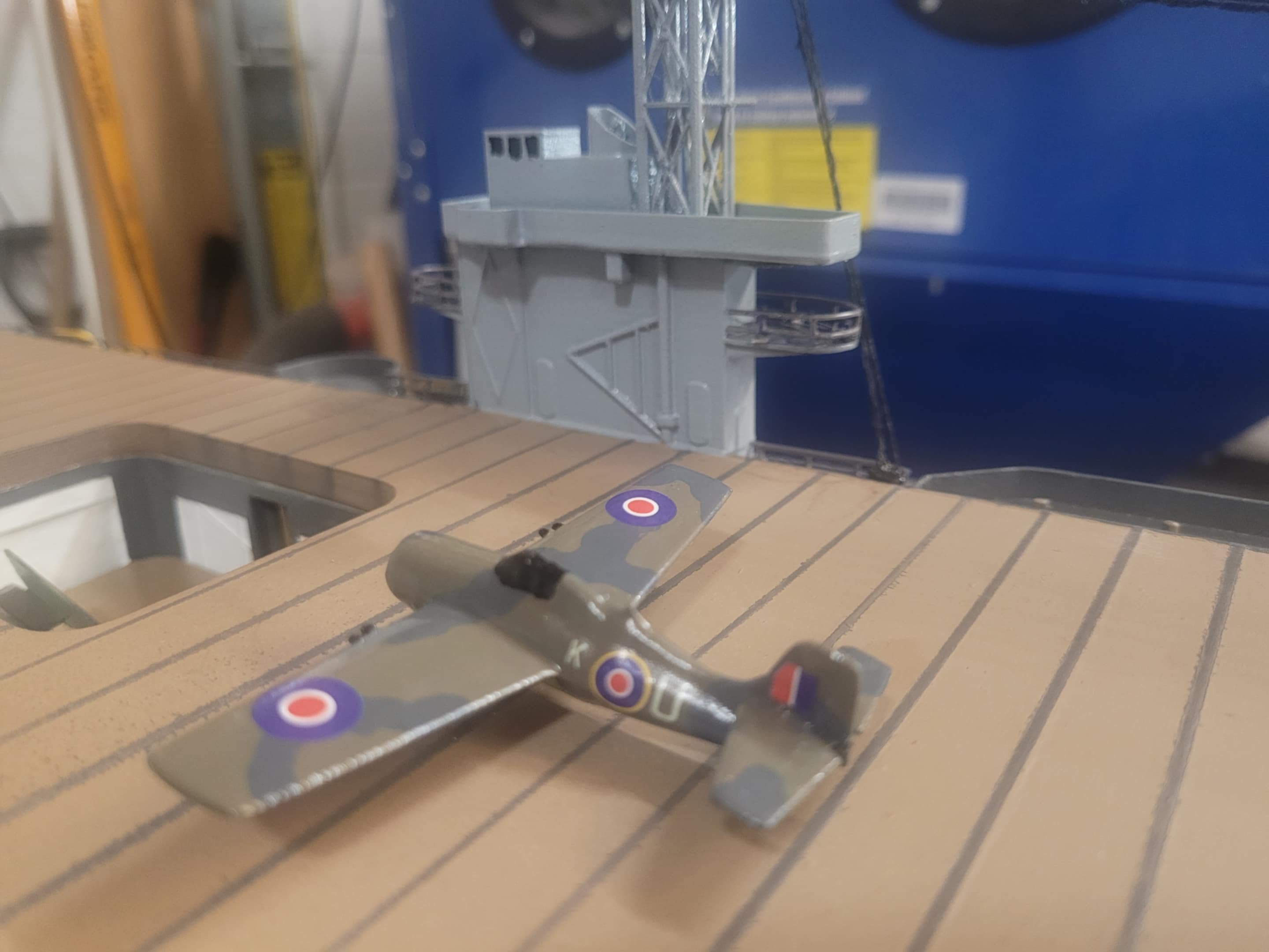
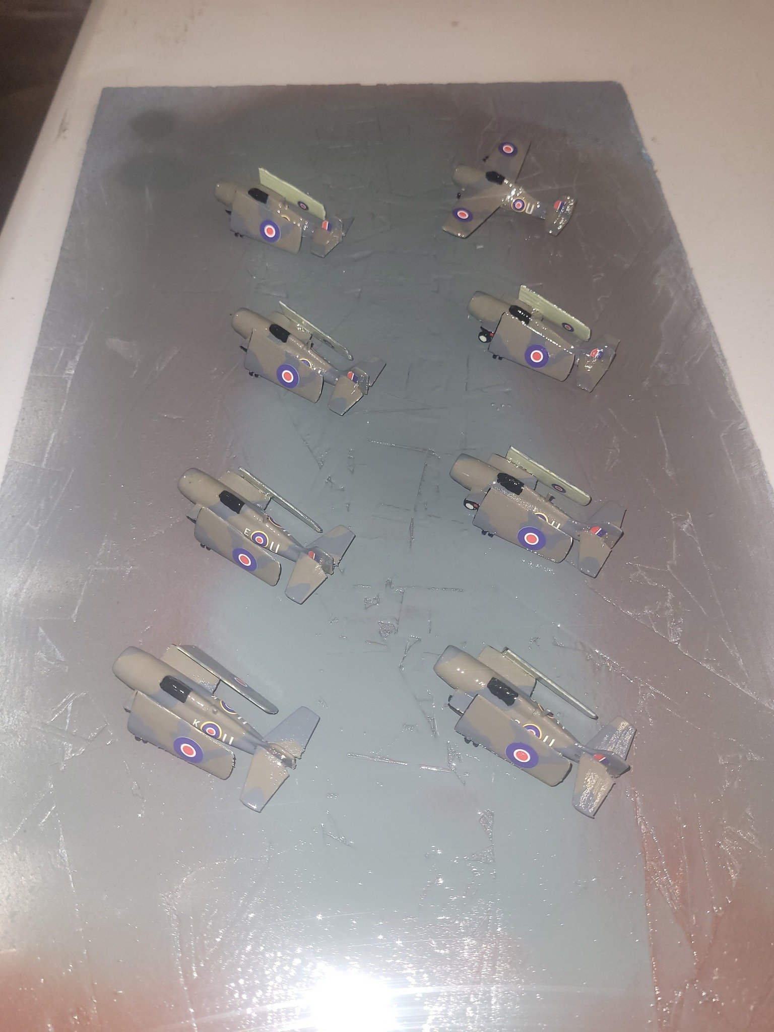
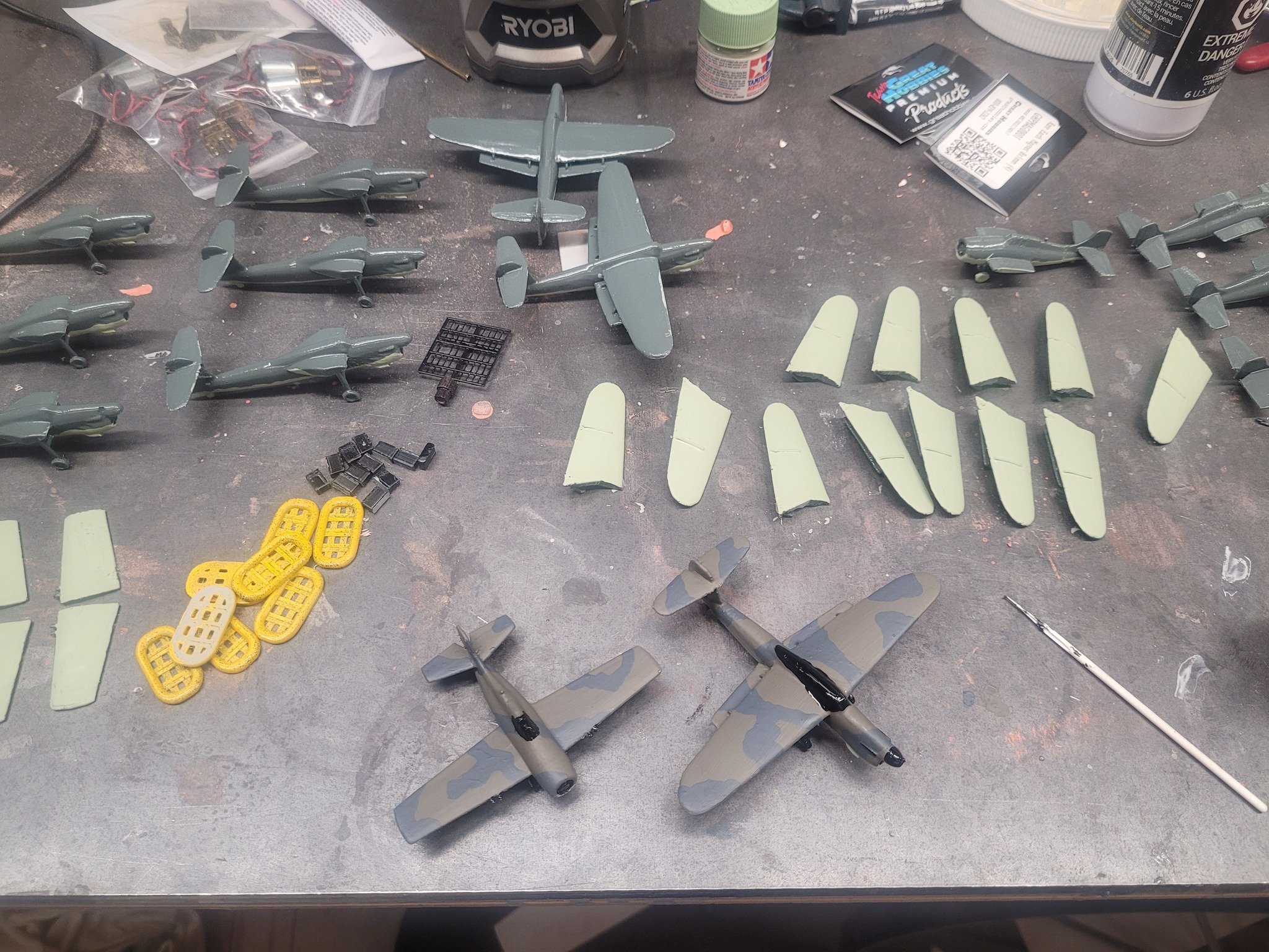
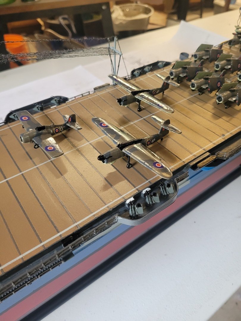
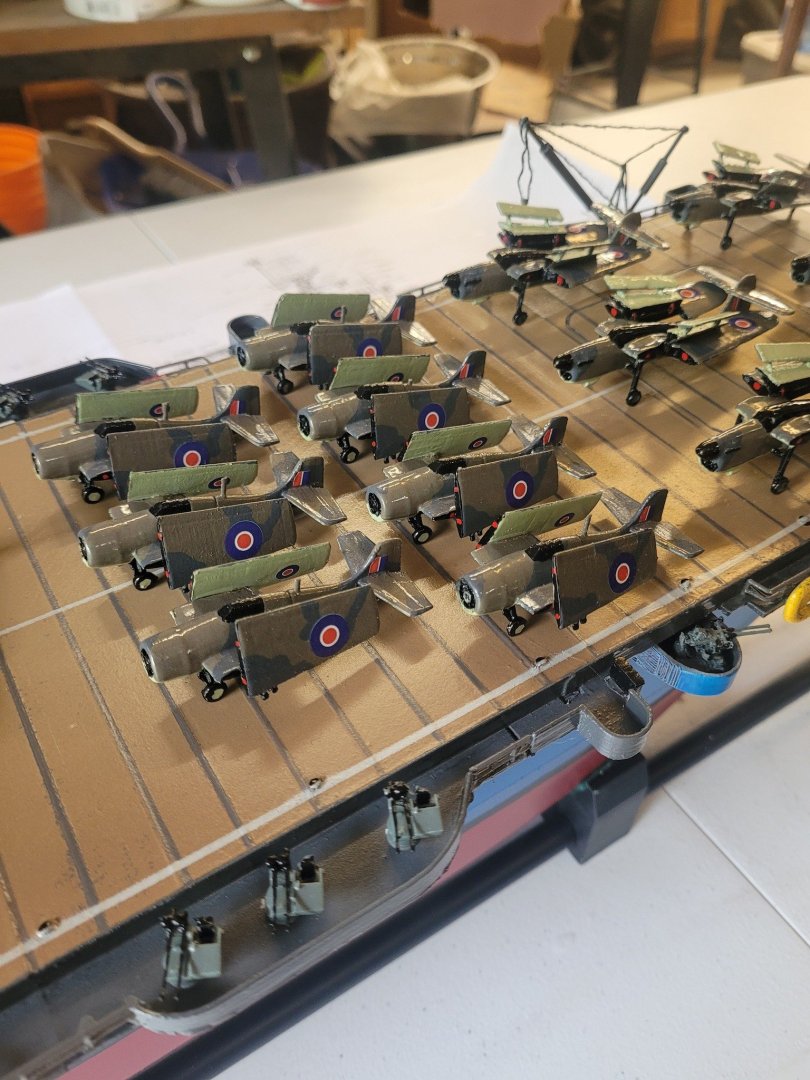
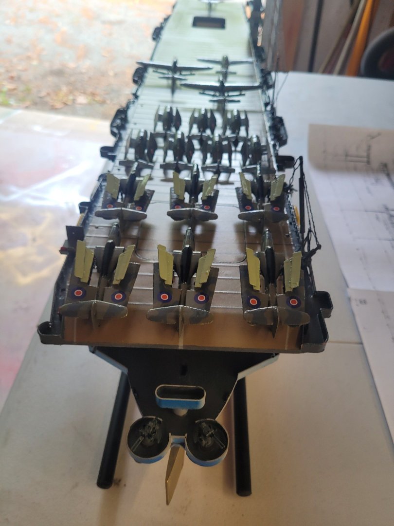
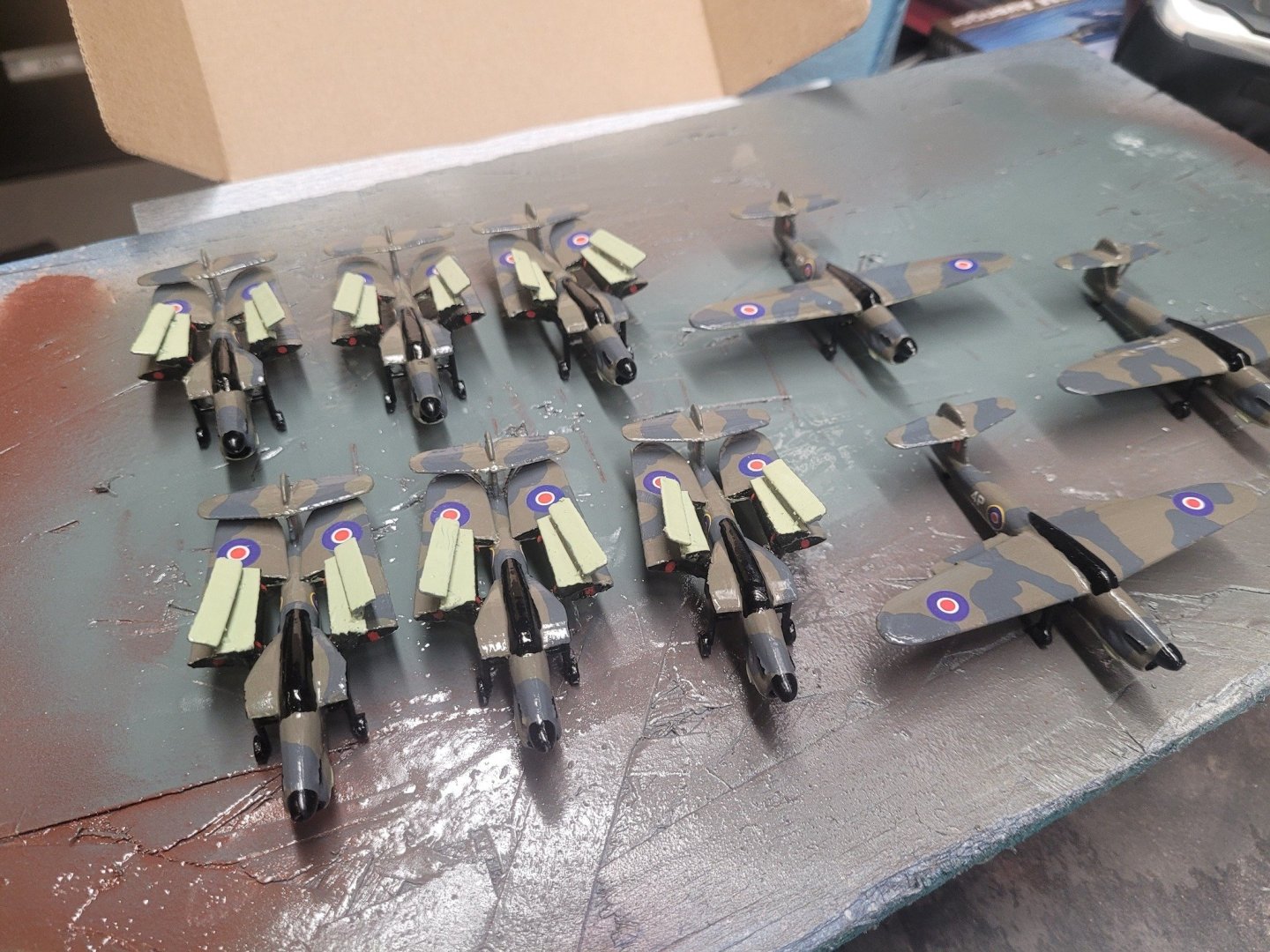
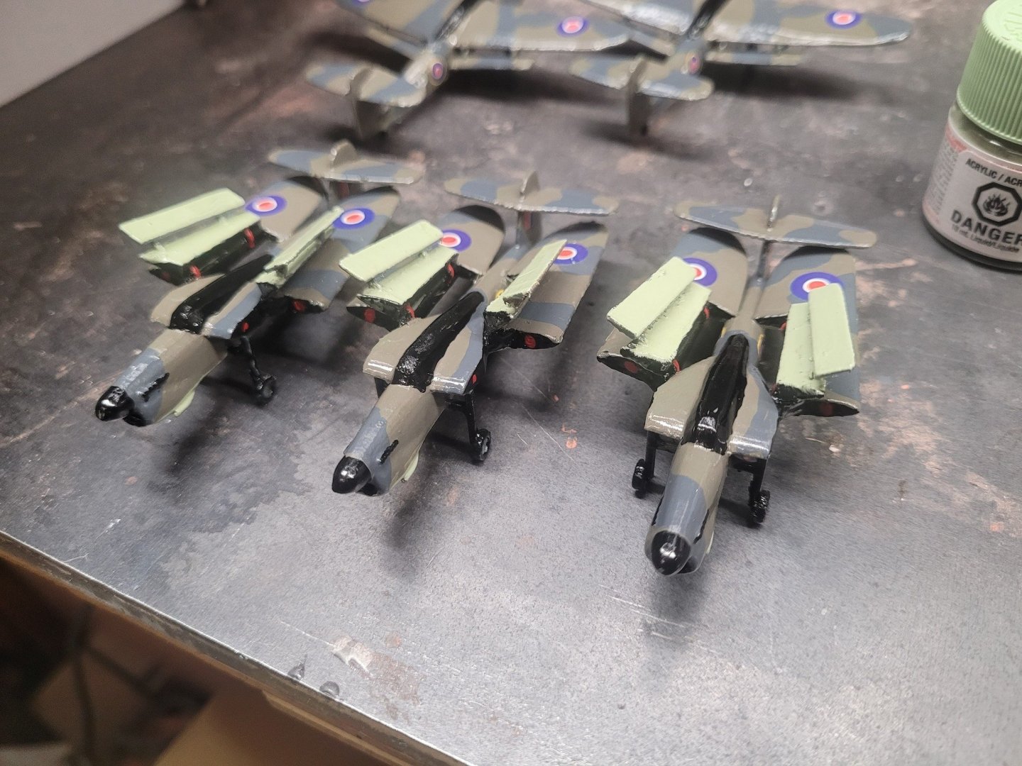
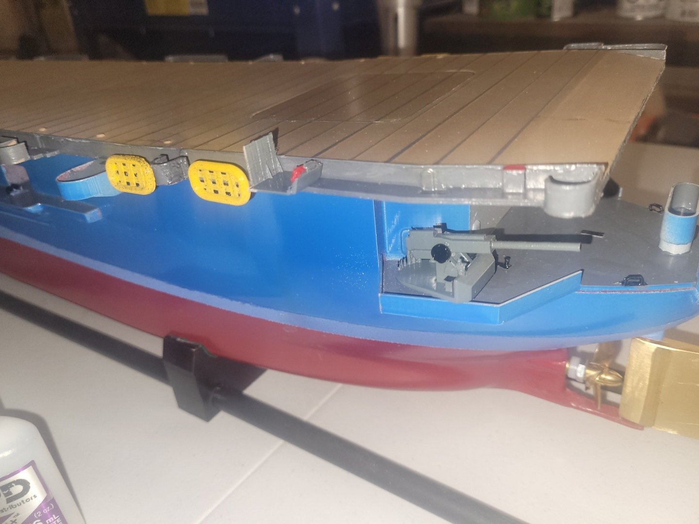
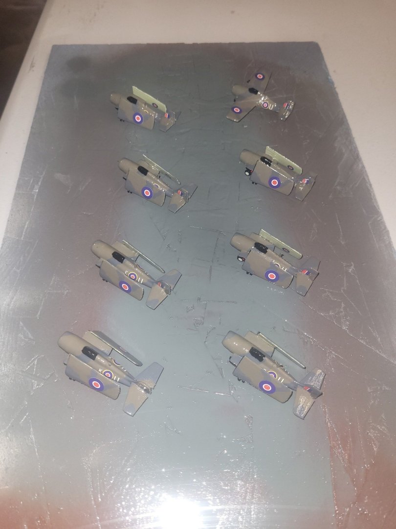
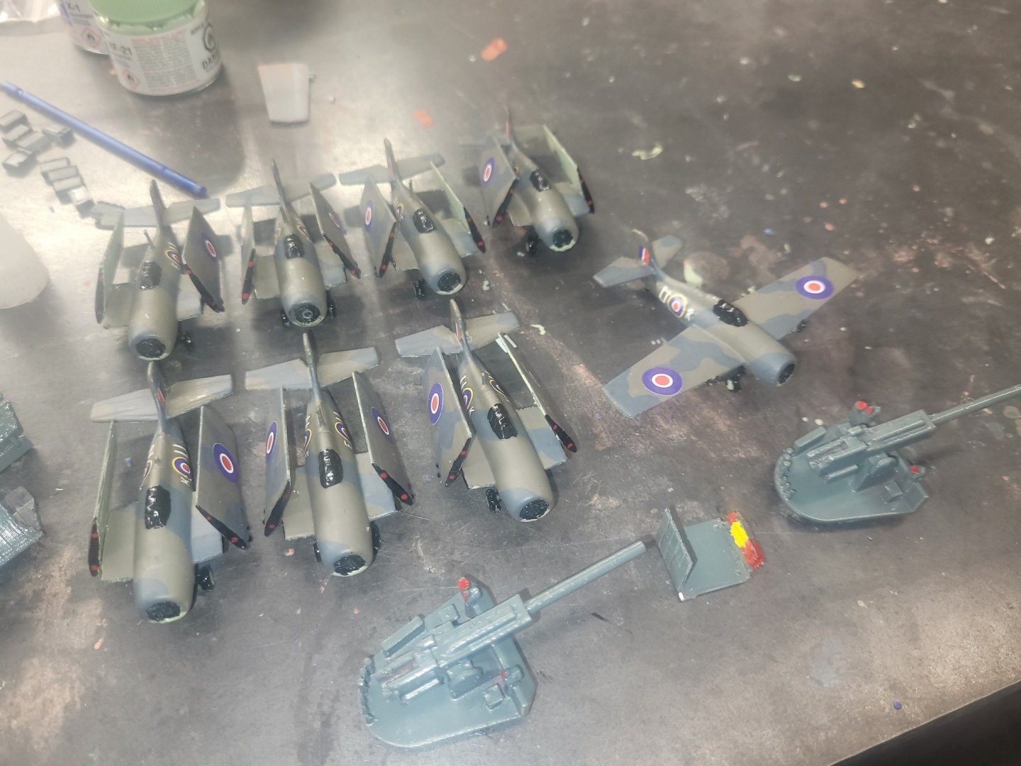
Ballast adjusted a bit today so the bow will ride a bit higher in the pond when I have her out on Sunday. The Martlets are done and now have 2 coats of clear gloss sealing them. The new wings for the Barracudas are half-painted - almost ready for decals. Details have started to get added to the ship now as well - the 5" guns have been installed along with some life-rafts and the ship's boats. More details to go, but she's nearly done. My son has a football game tomorrow that I'm off to watch then tomorrow evening I'll be puttering about with this to get her ready for a fun float with the Guild on Sunday morning.
- 51 replies
-
- 5
-
-
- Puncher
- escort carrier
- (and 1 more)
-
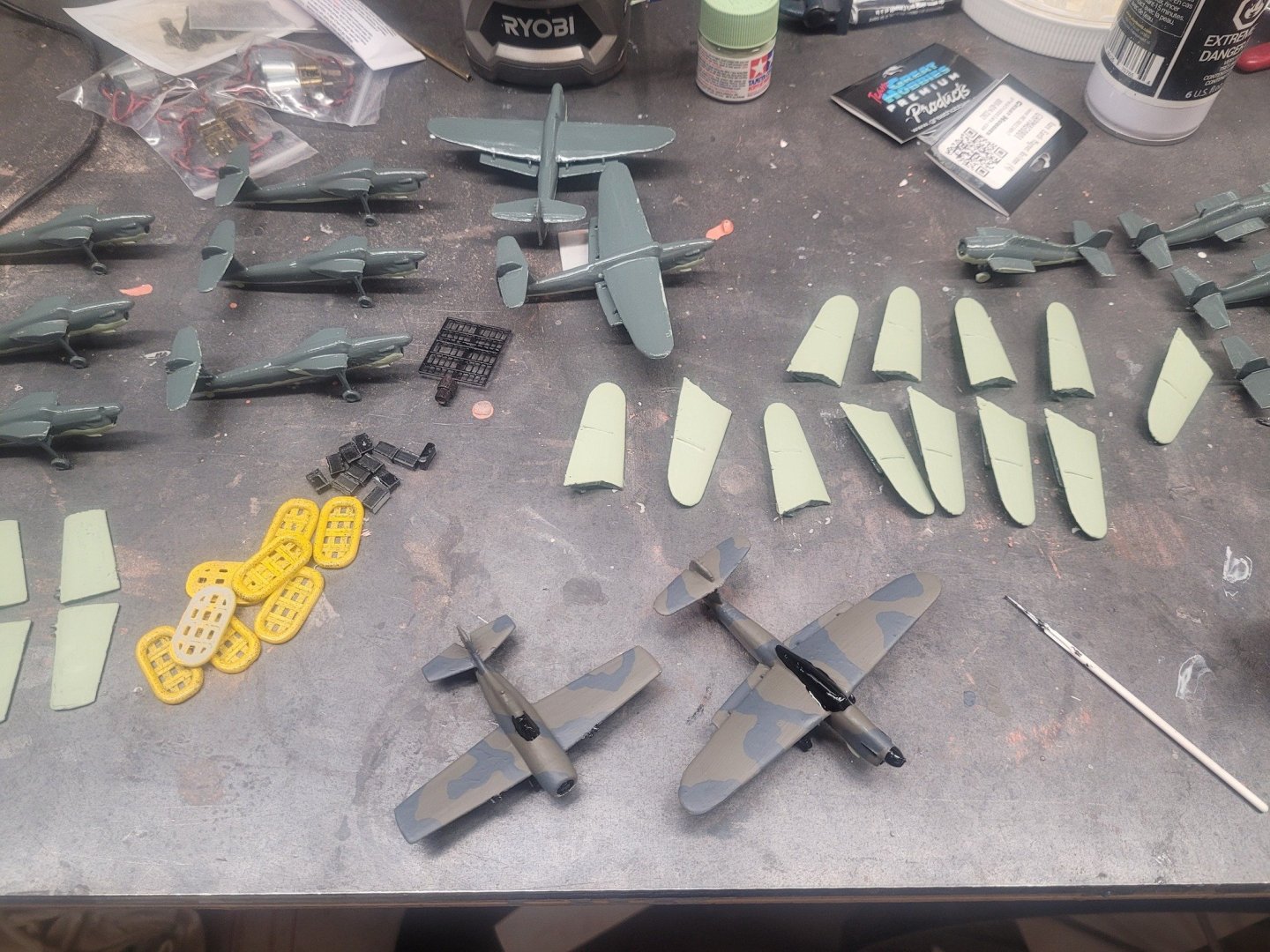
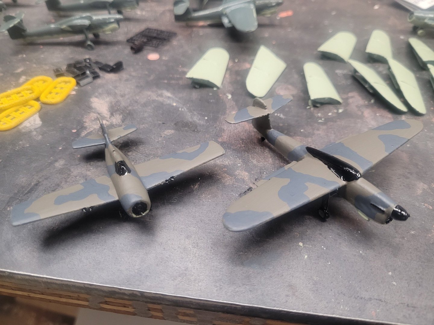
Overall weight is probably 10 pounds or so? As for the air det, those are mostly for display. The decals are on and will end up with a couple layers of overall clear coat spray applied to seal them in. The only ways that the aircraft would be certain to stay on the flight deck 'at sea' on the model would be to glue them in place, or to inset magnets into the landing gear and underneath the flight deck to hold them. Intent is not to sail with the 'actual' air det - I'm going to end up making some 'sailing' airplanes that I don't bother to decal up - they'll look good from afar though. When the ship is on display at a show or whatever I'll swap on the 'good' airplanes. The rudder being considerably overscale makes her perform quite well in turns, but, if I do a 'hard over' she'll really slow down as it ends up acting as a brake as well.
- 51 replies
-
- 1
-
-
- Puncher
- escort carrier
- (and 1 more)
-
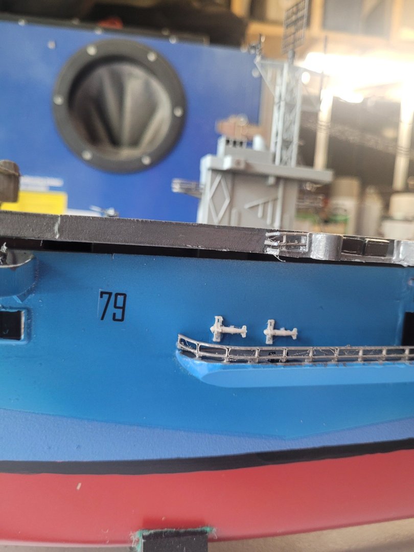
David, Agreed, the model is too low in the water - that's an easy ballast fix which I'll work on the next time I get her to the pond. Also, while you may have sent me plans, I was mostly focused on having this model be a bit better than the Glynn Guest USS Bodega Bay model - which is at best a stand-off scale ship. An observation - you have a tendency to almost always point out the flaws....I don't think you've ever posted a positive "hey, that looks good" type post. Are you naturally a negative personality, or is this your internet persona? My HMCS Bonaventure model is, truly, huge, and is going to be a challenge to get to/from the pond let alone launching her. My desire was to have a more portable RCN-ish Aircraft Carrier model that's more detailed than the Glynn Guest model. In that I have succeeded. I'm at the point of doing minor ballast adjustments, adding the detail bits, and finishing the Air Det up. (Got 3 of the Martlets decalled up last night and a start on the rest.) This was never going to be a 100% museum quality build. That said. One of the people who's downloaded the free file set that I released is building his up as a display model for the museum he volunteers at, so....I guess it can be whatever you make it into? NS
- 51 replies
-
- 2
-
-
- Puncher
- escort carrier
- (and 1 more)
-
Ken....your magic math has impressed me....I'll upload a video of her sailing in a bit once get it put together. The ESC is a hobbywing 1080 and the motor is a 400 size I think. I realized that it's very easy to overpower models, so I've limited the throttle to 60% - if I remove the limit, she'll go a bunch faster, but yes, the water over the bow would be a big concern. I'll probably drop some of the ballast to get the bow up a bit.
- 51 replies
-
- 1
-
-
- Puncher
- escort carrier
- (and 1 more)
-
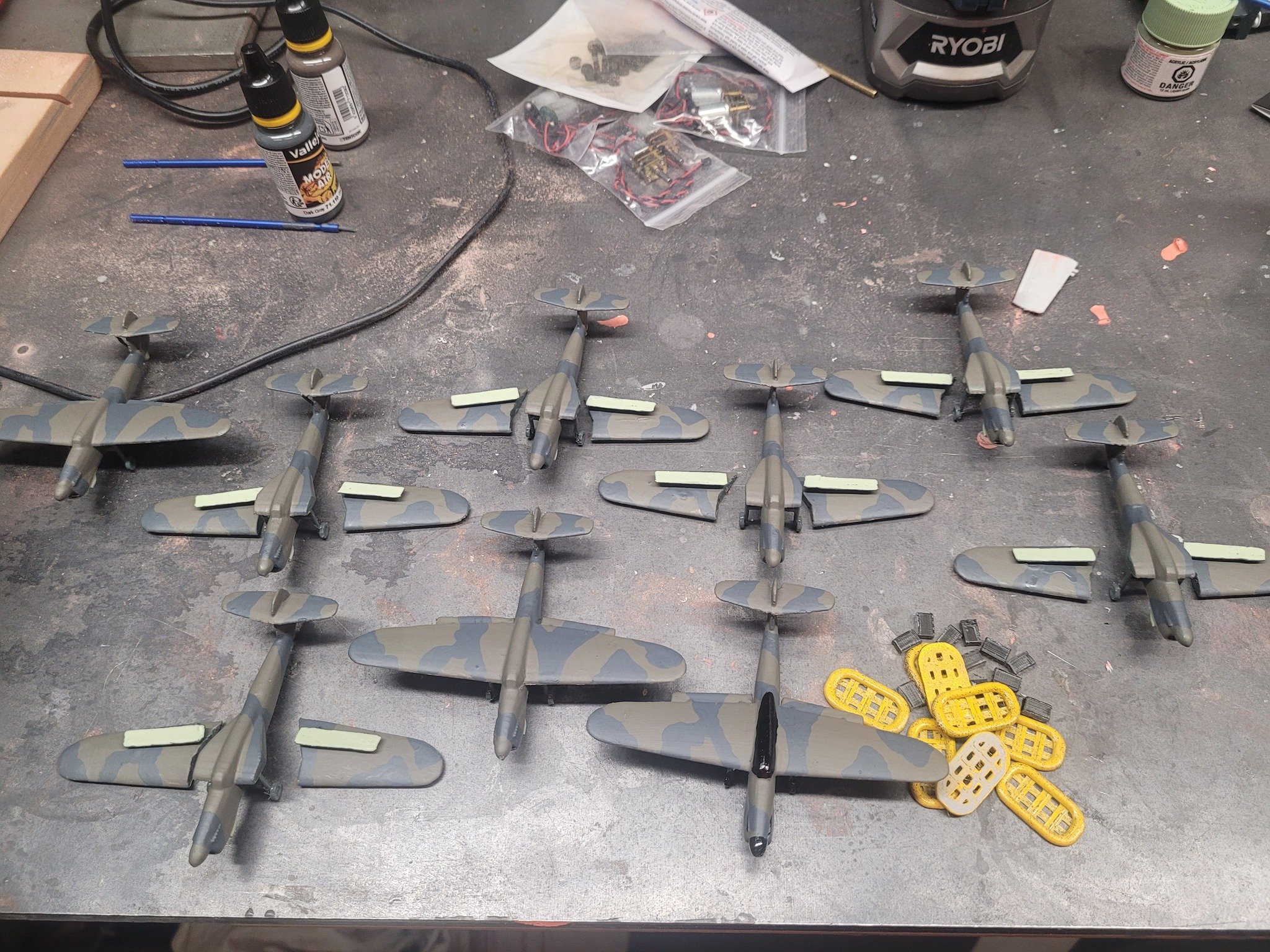
I did a bit of google-fu and discovered that I need to re-design and re-print the Barracuda wings for the ones in the folded position. That's in progress...
- 51 replies
-
- 1
-
-
- Puncher
- escort carrier
- (and 1 more)
-
Home from vacation with the family, back to work again, and finding some time to putter away on Puncher. She's headed to the pond tomorrow with the club - we'll see how she runs!
- 51 replies
-
- 4
-
-
- Puncher
- escort carrier
- (and 1 more)
-
US 6” gun by RGL - FINISHED - Panzer Concepts
NavyShooter replied to RGL's topic in Non-ship/categorised builds
Ahoy Greg! I came across a video from Youtube today that made me go digging and find this thread again. For those who are interested, here's a 3D visual of the process to emplace/assemble a larger 12" 1918 howitzer - but the string of steam tractors from this thread made me go digging here to link this build in. Gives an appreciation for how massive these guns were! 12-inch Howitzer 1918 Part 1 - progress so far -
https://www.youtube.com/shorts/bmN5wq2bTqs Ballasting and maiden voyage conducted today! Still work to do, the forward elevator mechanism needs to be installed which will obviously adjust the ballasting, but I've got 2 pounds of free lead weight that I can move/remove as needed to fix that up. Then the detail bits get added! Very pleased!
- 51 replies
-
- 1
-
-
- Puncher
- escort carrier
- (and 1 more)
-
Flight deck tie-down lines are now marked, along with the catapult!


- 51 replies
-
- 2
-
-
- Puncher
- escort carrier
- (and 1 more)
-
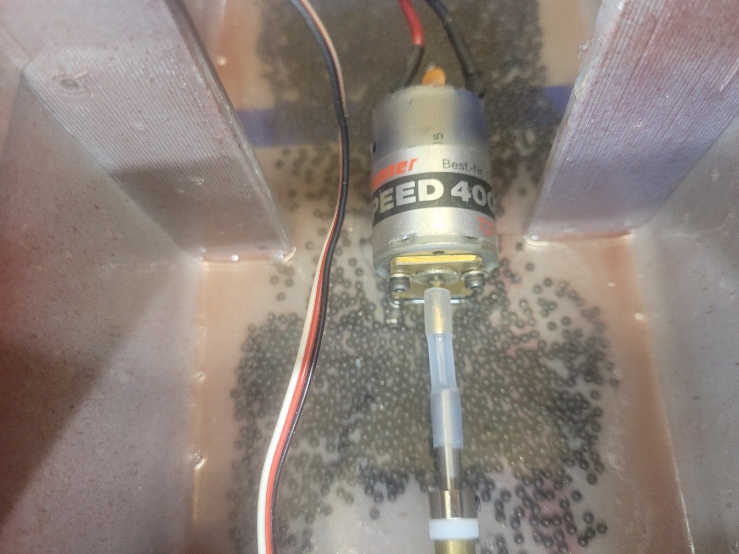
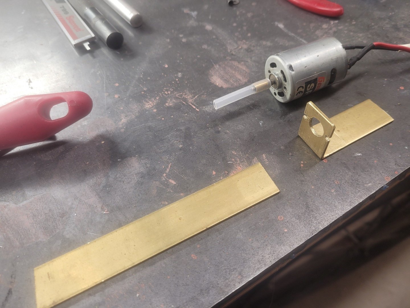
Good thing is that I'm not an aviator (except as a licensed drone operator!) I'm about 80% back to where I should be - met with a physiotherapist today and got to the root of things. Getting better. Went for a short drive today and that went OK. Also back in the shop and got a motor mount assembled, and epoxied in place.
- 51 replies
-
- 2
-
-
- Puncher
- escort carrier
- (and 1 more)
-
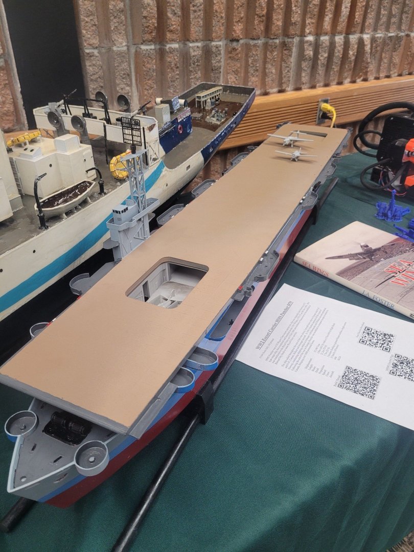
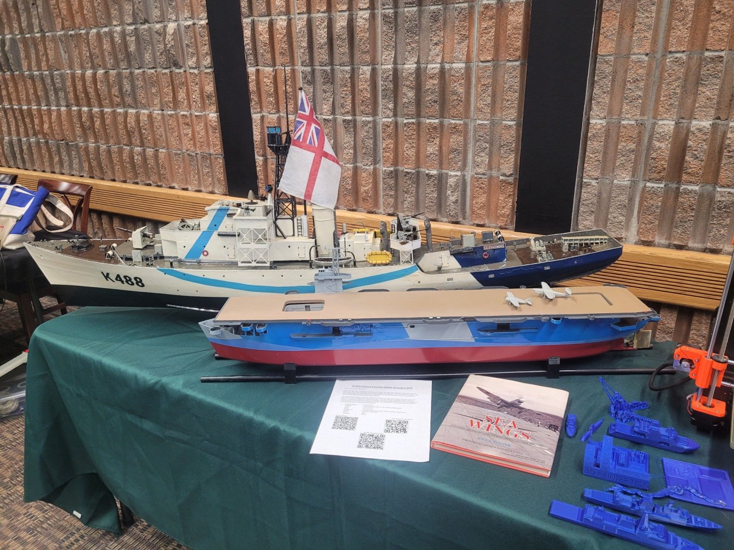
Here's pictures of Puncher at the Shearwater Hobby Show a couple months back. Not much change in looks between then and now....I've been busy!
- 51 replies
-
- 3
-
-
- Puncher
- escort carrier
- (and 1 more)