
NavyShooter
-
Posts
693 -
Joined
-
Last visited
Content Type
Profiles
Forums
Gallery
Events
Everything posted by NavyShooter
-
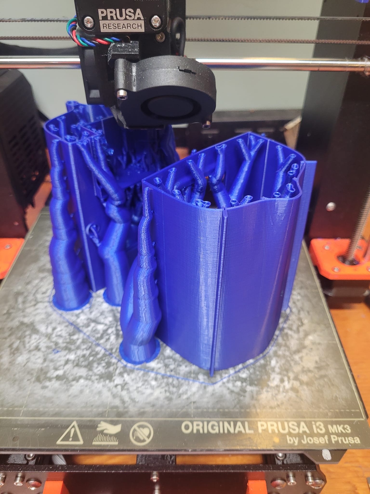
 Yes! It's actually fairly straight-forward. I will suggest buying a good quality printer though - I have had several "poor to OK" printers, but have replaced those with a GOOD one (Prusa MK3S+) and it's got almost 400 days (9600 hours) of printing time on it, and still produces a good finish. Understanding the relationship between design - slicing - printer capability is a key thing to remember or learn. Trying to print a gun-shield that's too thin will result in poor results. Design is a compromise between printer capability and resolution.
 -
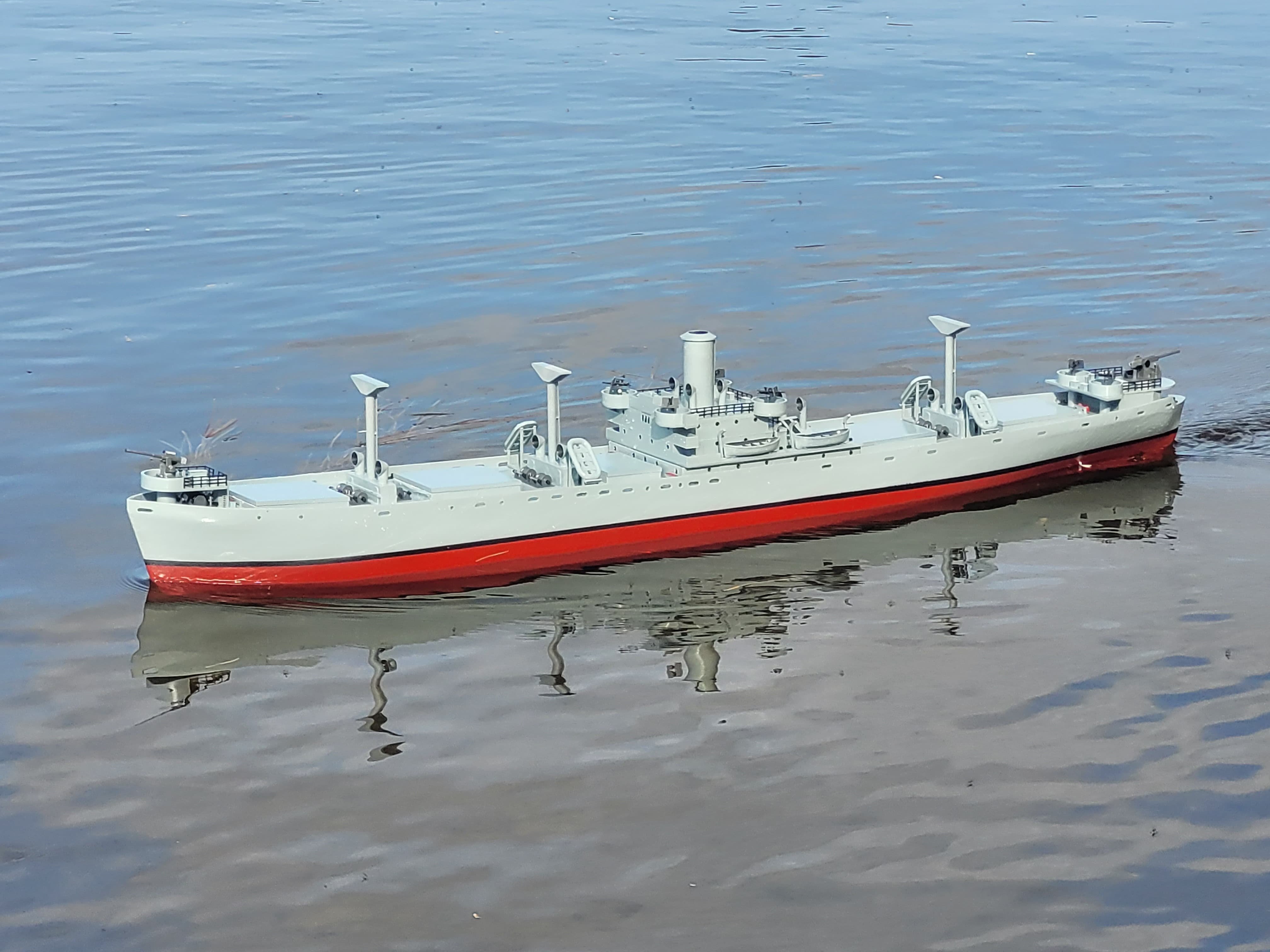
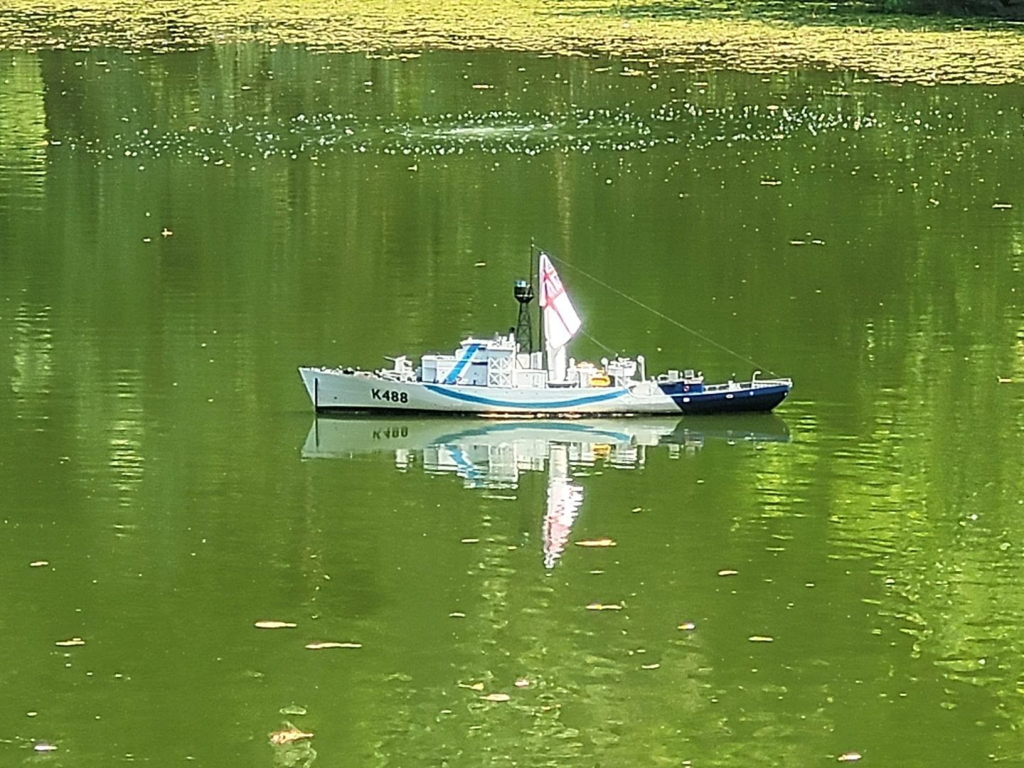
I had printed the booms last year, but never attached them. I spent a few minutes last weekend and mounted them, and did some basic rigging so that they're still removable in case I need to. It makes the ship look much more complete. NS


- 54 replies
-
- 3
-

-

-
- Liberty Ship
- Finished
- (and 2 more)
-
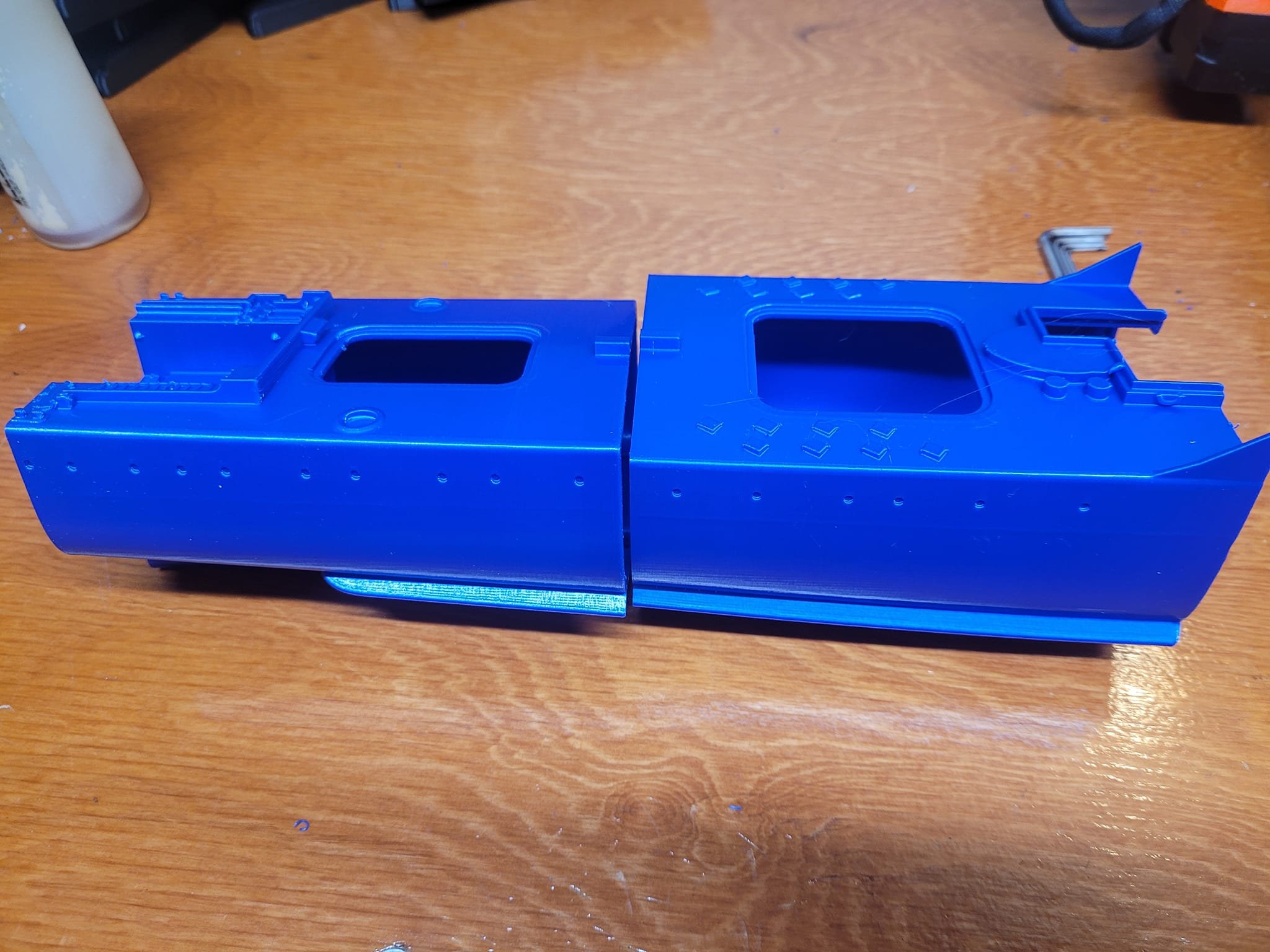
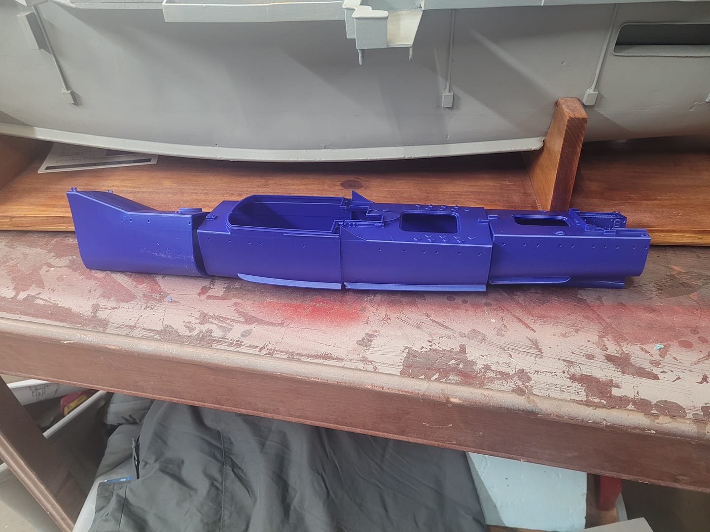
Hull is printed! I glued together some of the modules last evening, did a bit of filling and sanding - and this morning I pulled the last two modules off the printer and set them alongside to see how things look. Overall, the model is right on about 32 inches, which is a handy size for transport. The superstructure is on the printer now, should be done tonight. I'm pondering making this a 4 channel RC - - Throttle - Rudder - Gun rotation - Radar Rotation/Lighting I think this one's too small to add a speaker system/audio channel. NS

-
OK! 2 more modules printed and complete - here we see the size of things - overall it's at 21 inches right now, 2 modules left to print so she'll be just over 30" complete. A decent size!
-
I referenced the builder's short build video that he has linked on both Cults and Youtube, and managed to order the same prop shaft, rudder, and some other bits online. They'll probably take a month to get here (UK source, not Amazon) so we'll see what that looks like. I'll probably have the hull/etc done by the weekend as this is only a small model. The 'fiddly bits' cost about 50 Pds Brit - 85-ish or so. NS
-
First modules complete - here's how they look! Next set of modules will be done tomorrow after work!


-
Marine Museum of the Great Lakes (Kingston Ontario)
NavyShooter replied to Diver's topic in Nautical/Naval History
Very nice! I love the piano in the middle of the compartment! -
STL file HMS Blackpool 🛥️ ・3D printer model to download・Cults (cults3d.com) Ahoy gents, I came across the above 3D print file over the weekend as I was puttering away and decided that it was worth the 5 Euros to download and print it. Appears to be 1/144 scale - ish. I'm thinking of using this as a 3D model for the 3D printing 'course' that I'm going to try and run. This uses about 650g of filament, and takes about 5 days of printing. The Liberty Ship from Thingiverse, printed at original scale (1/160 or N Scale) takes longer, and about double the amount of filament. So. I'm going to end up doing one of each to see how they work out. Starting with this one. The first modules of the hull are on the printer right now. Pictures will follow this evening! NS
-
That is...a LOT of rivets!!
-
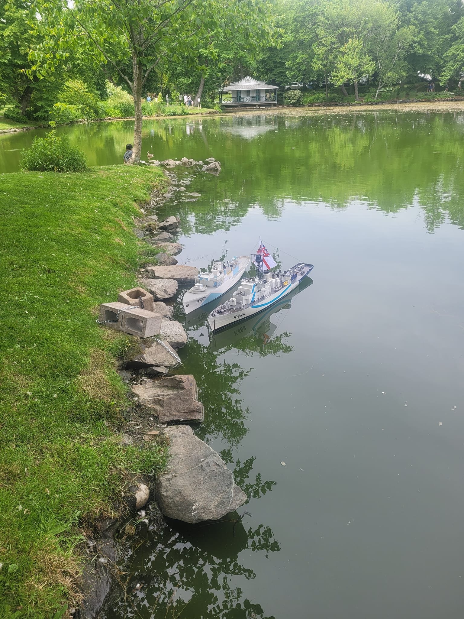
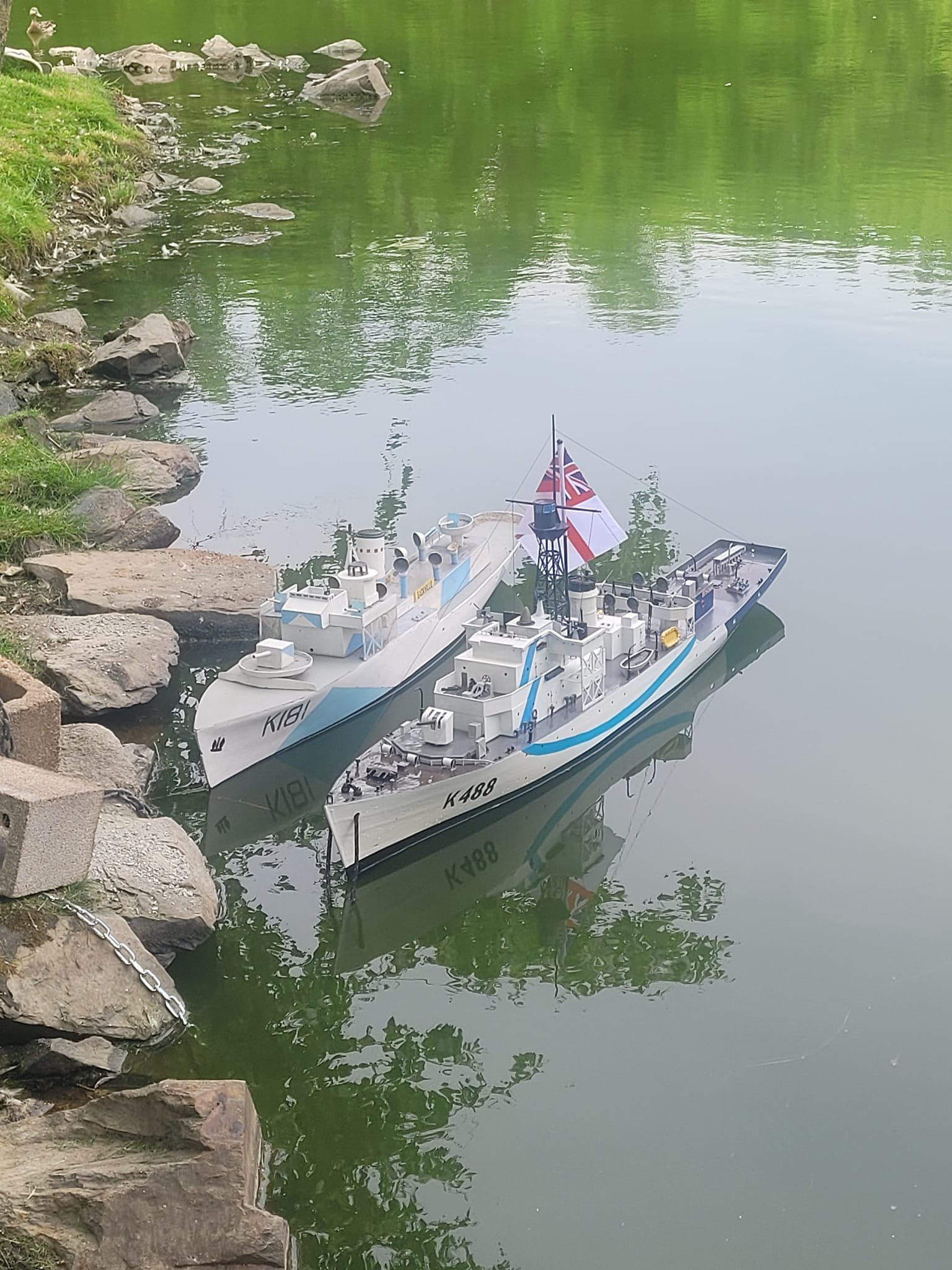
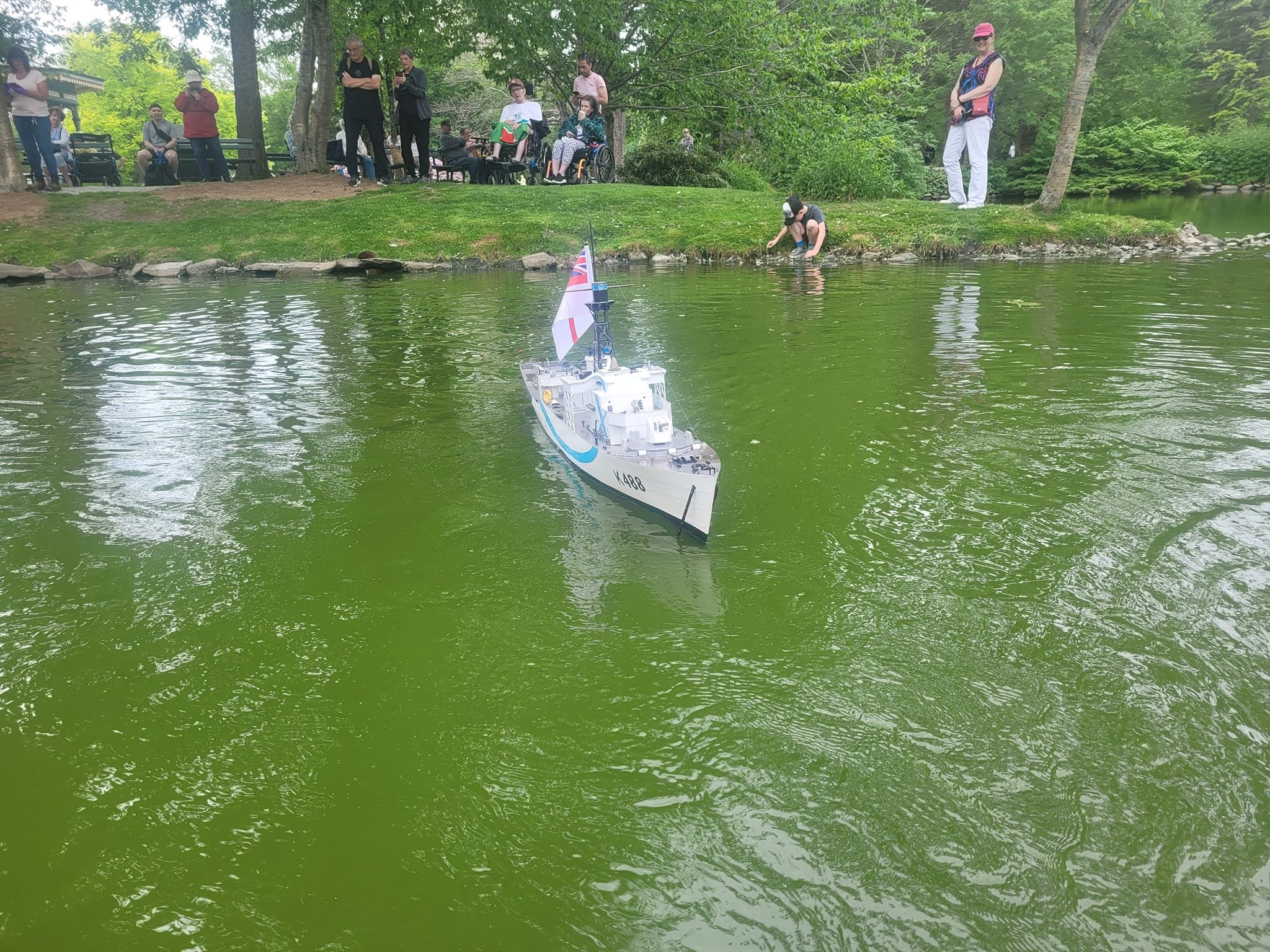
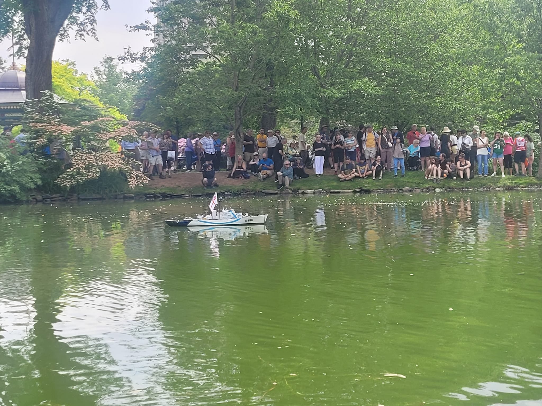
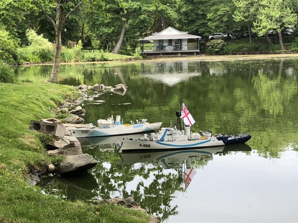
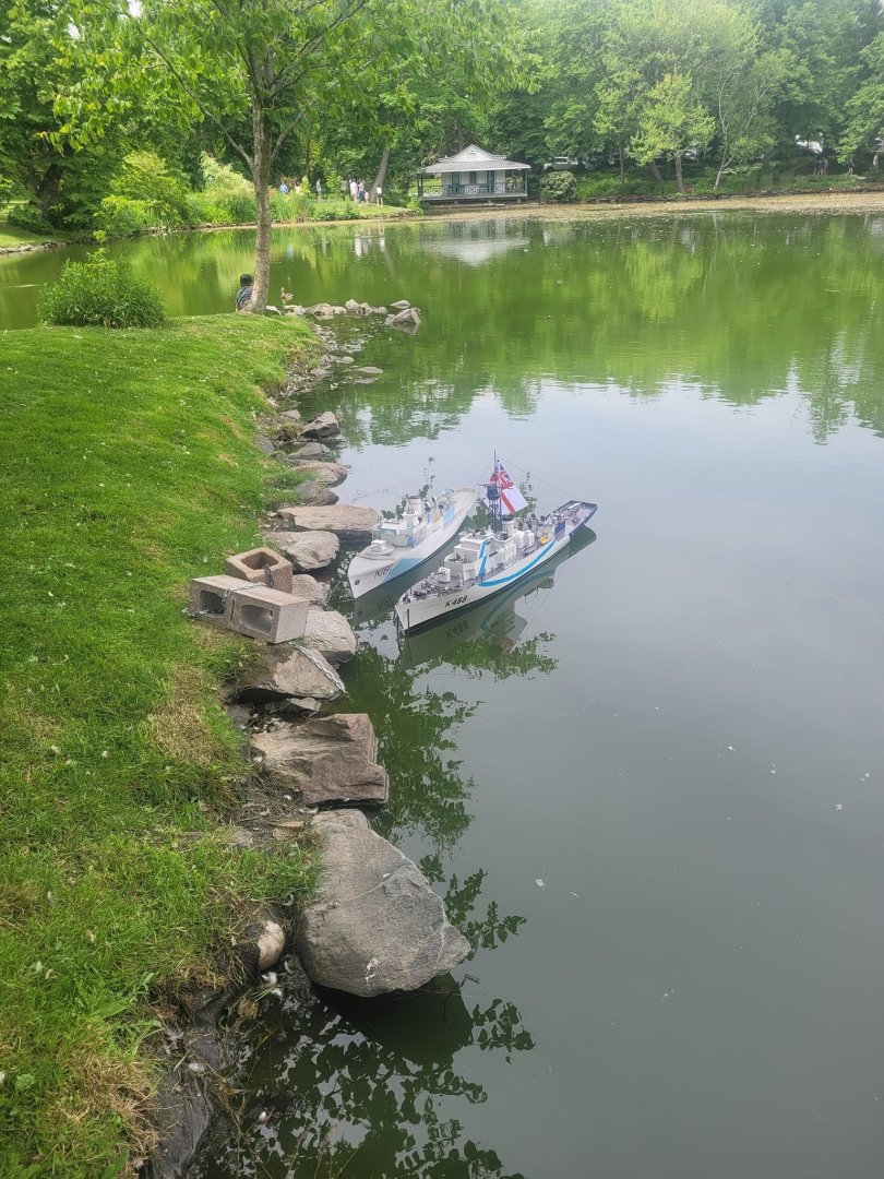
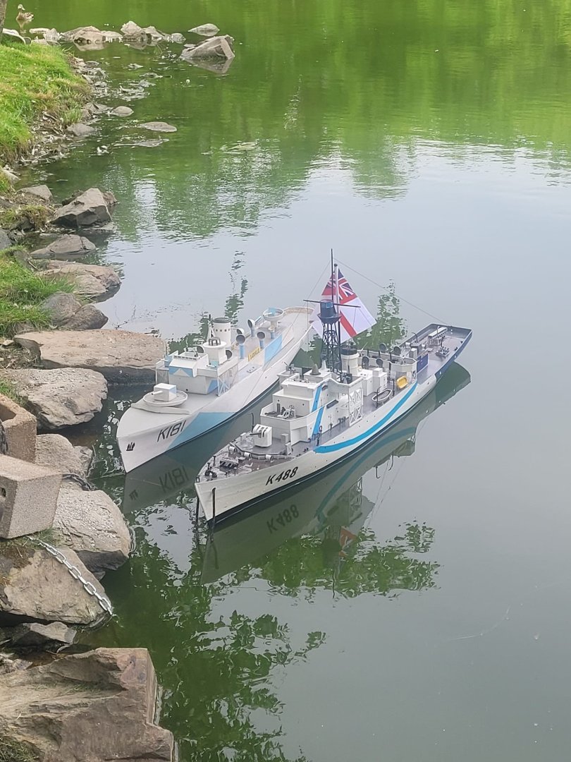
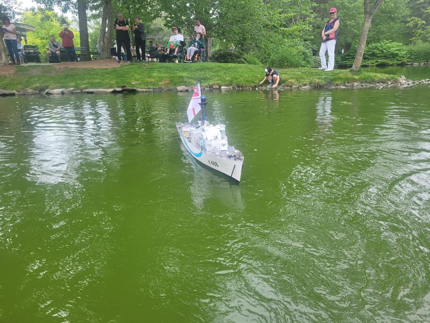
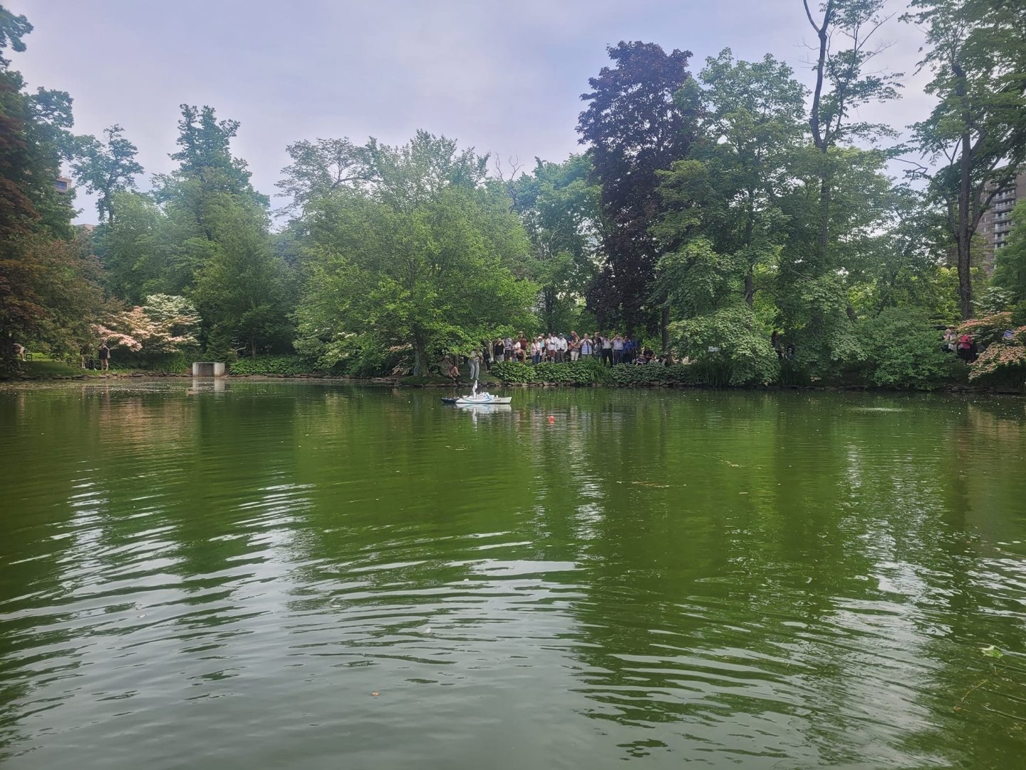
Got home from vacation, stopped by yesterday to have a look at the models in the pond. Looking good!


-
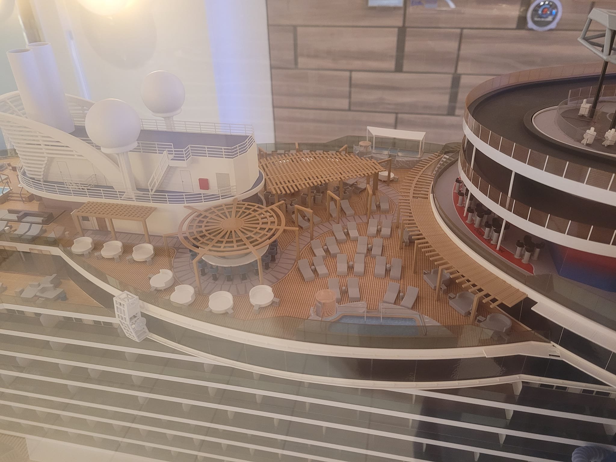
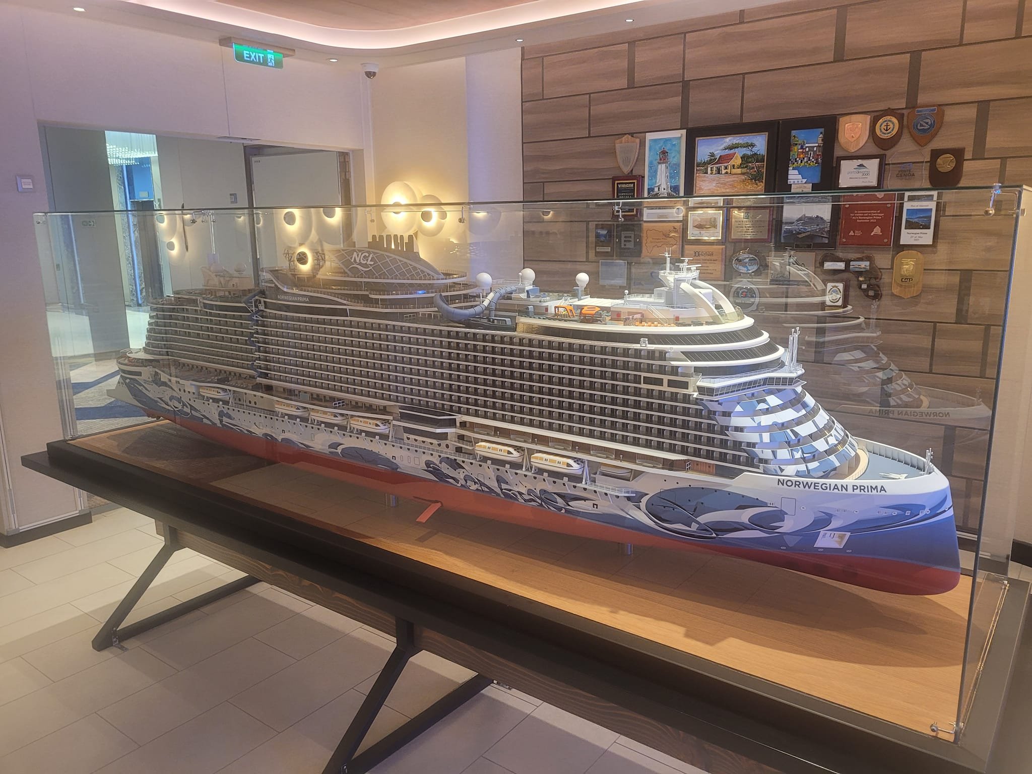
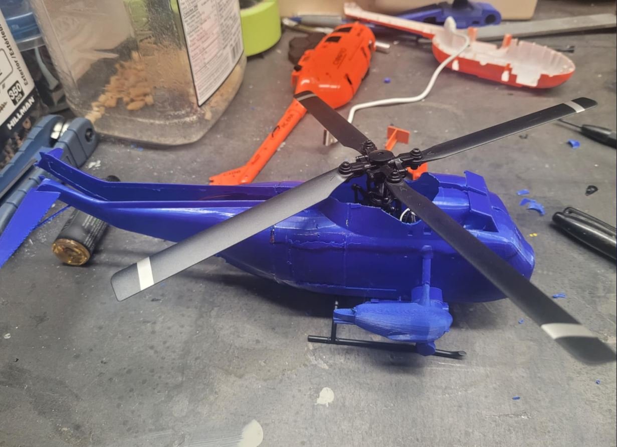
Test flight - took off in the garage, 'landed' in the garage....it wasn't pretty. But. It flew. I've also just returned from 2 weeks of vacation - did you know that most cruise ship's have a builders model onboard?


-
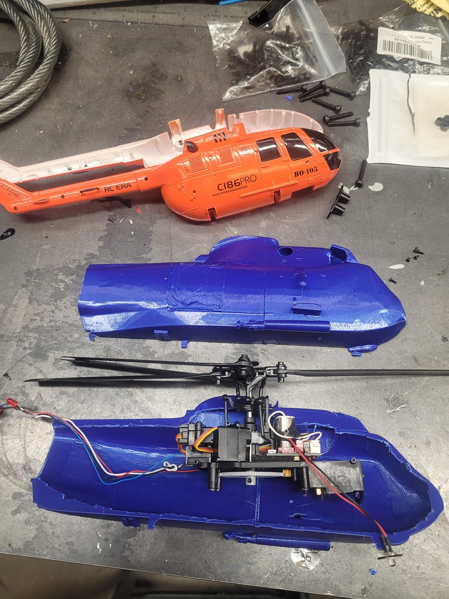
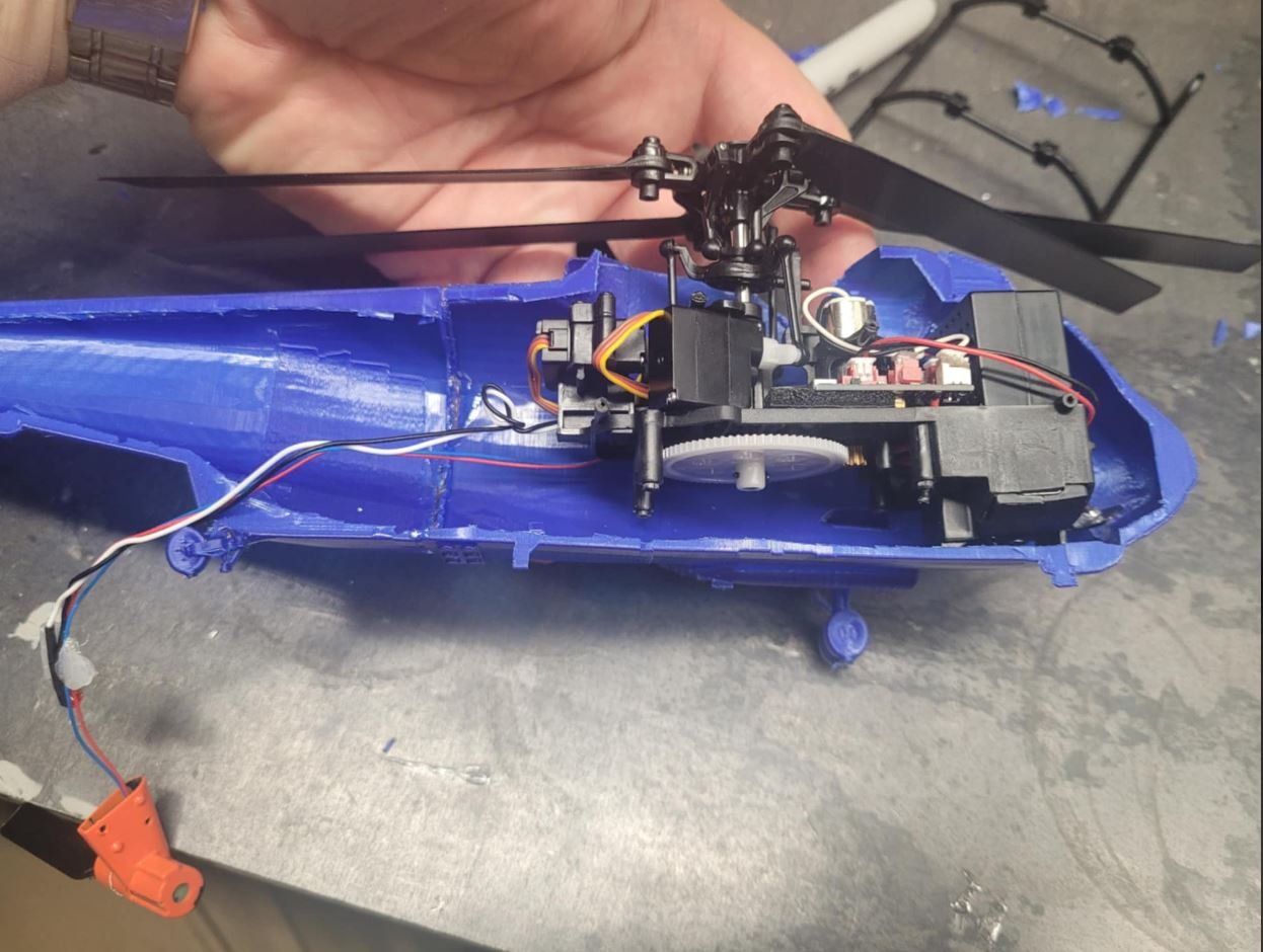
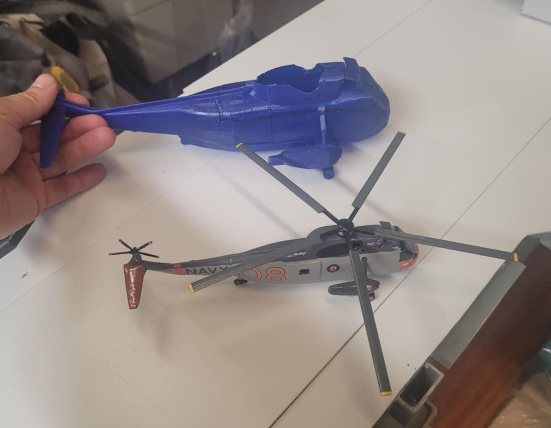
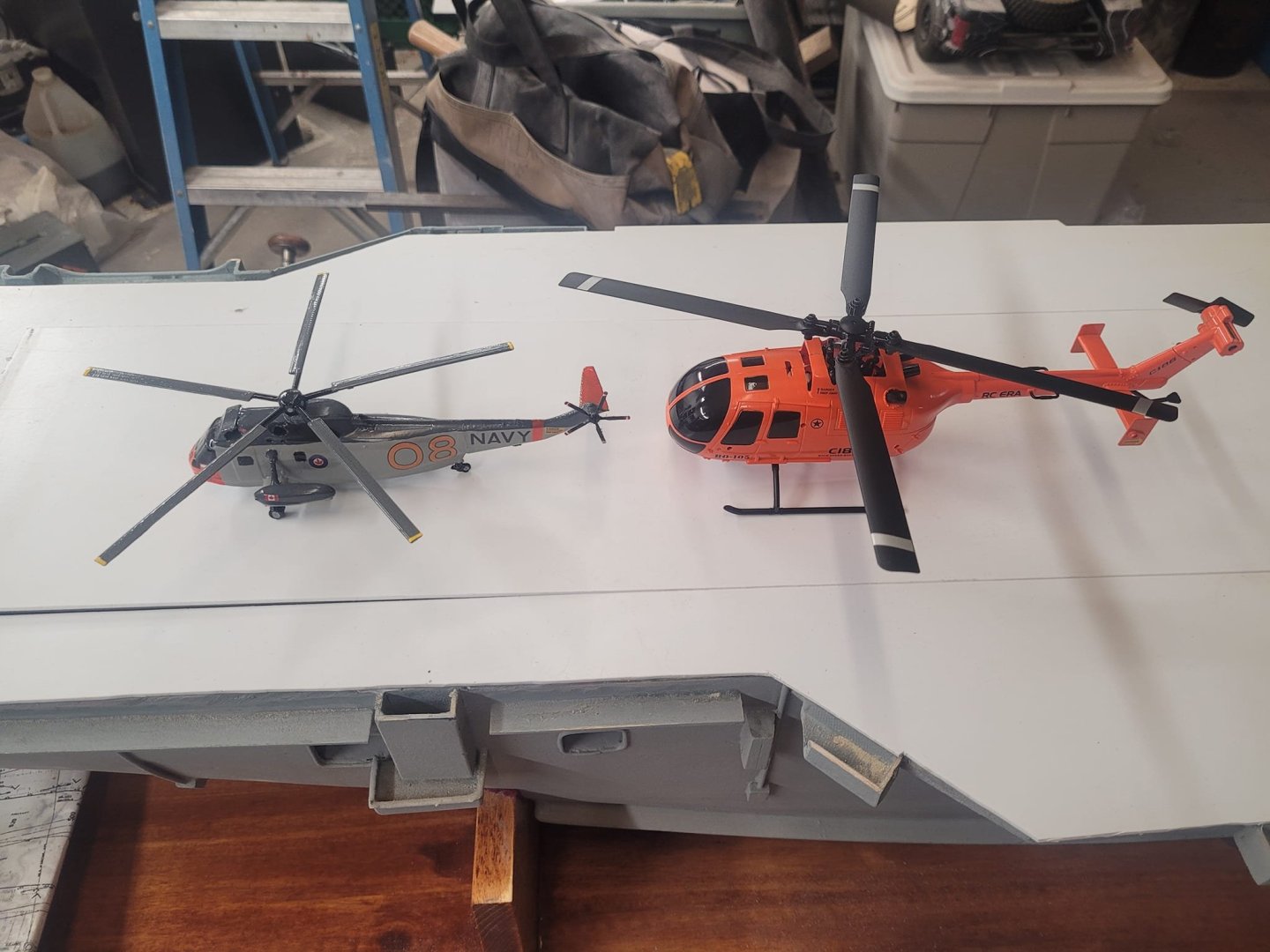
Comes out about 50% oversize...but...I think it'll do. I have to re-print the fuselage to make it about 5% taller - give a bit more space for the battery pack. The battery is 'normally' removed for charging, but I think I'm going to set this up to have the battery fixed in place, and I'll charge through a port I make in the side by the cockpit.
-
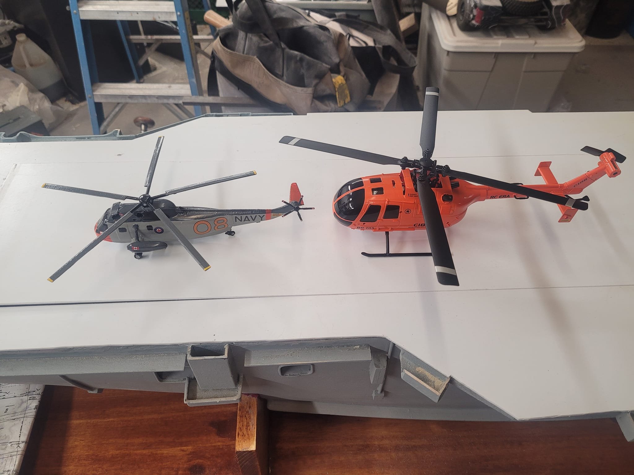
New hobby shop opened up in town - I got an invite to the pre-launch opening and tax free sale...so I bought a little bitty helicopter. Concept - strip the orange fuselage off, and fit a 3D printed Sea King fuselage...then I can launch it from the ship while at sea and fly it home!!!

-
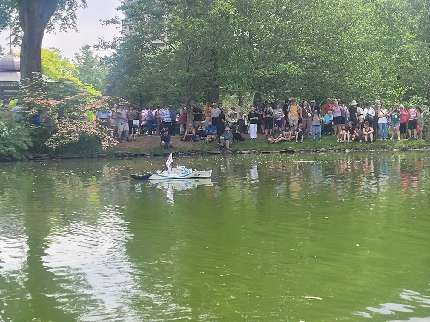
Thank-you! I'm hoping this public visibility brings some interest, and maybe new folks in the door to some of our meetings.
-
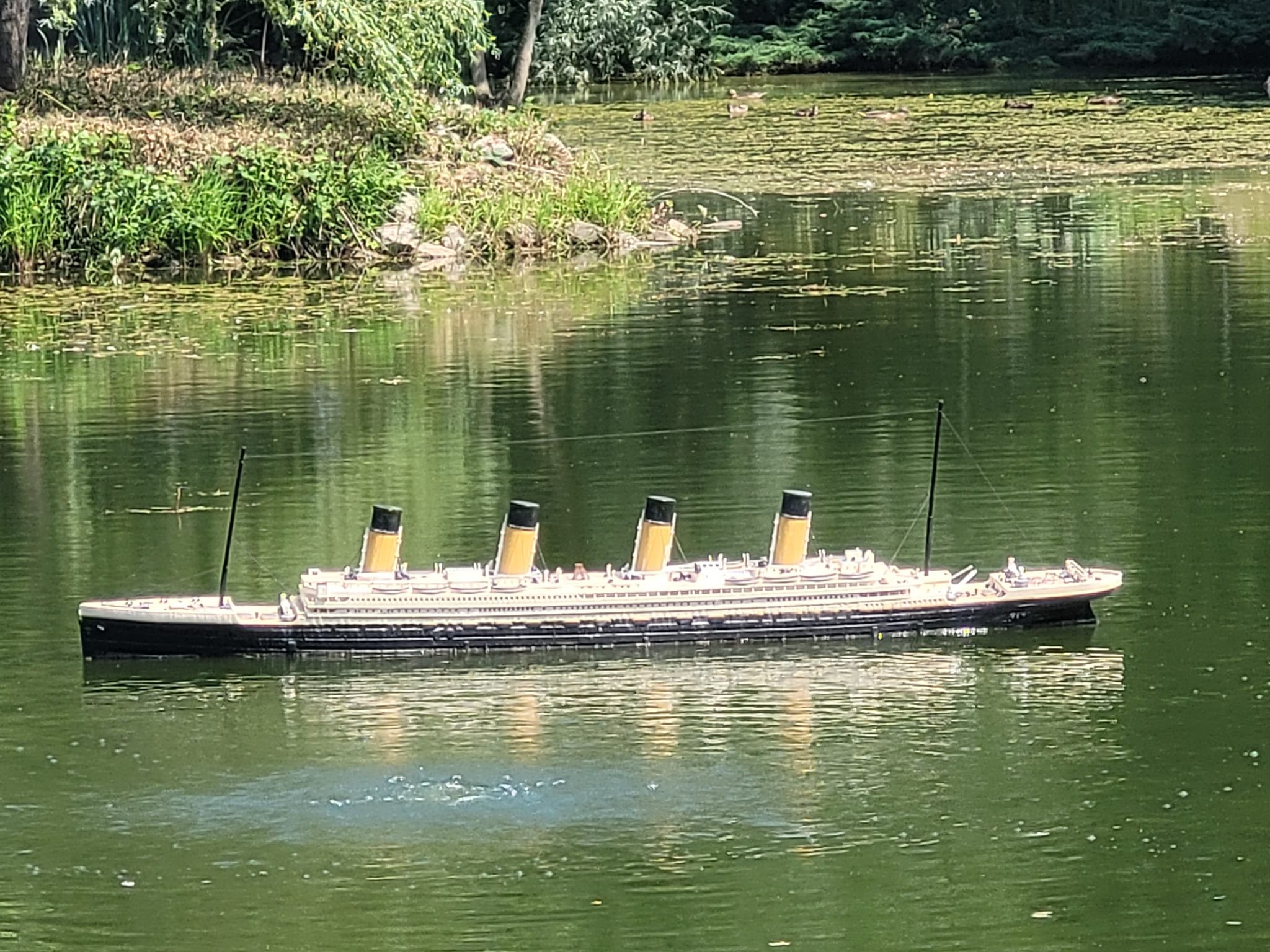
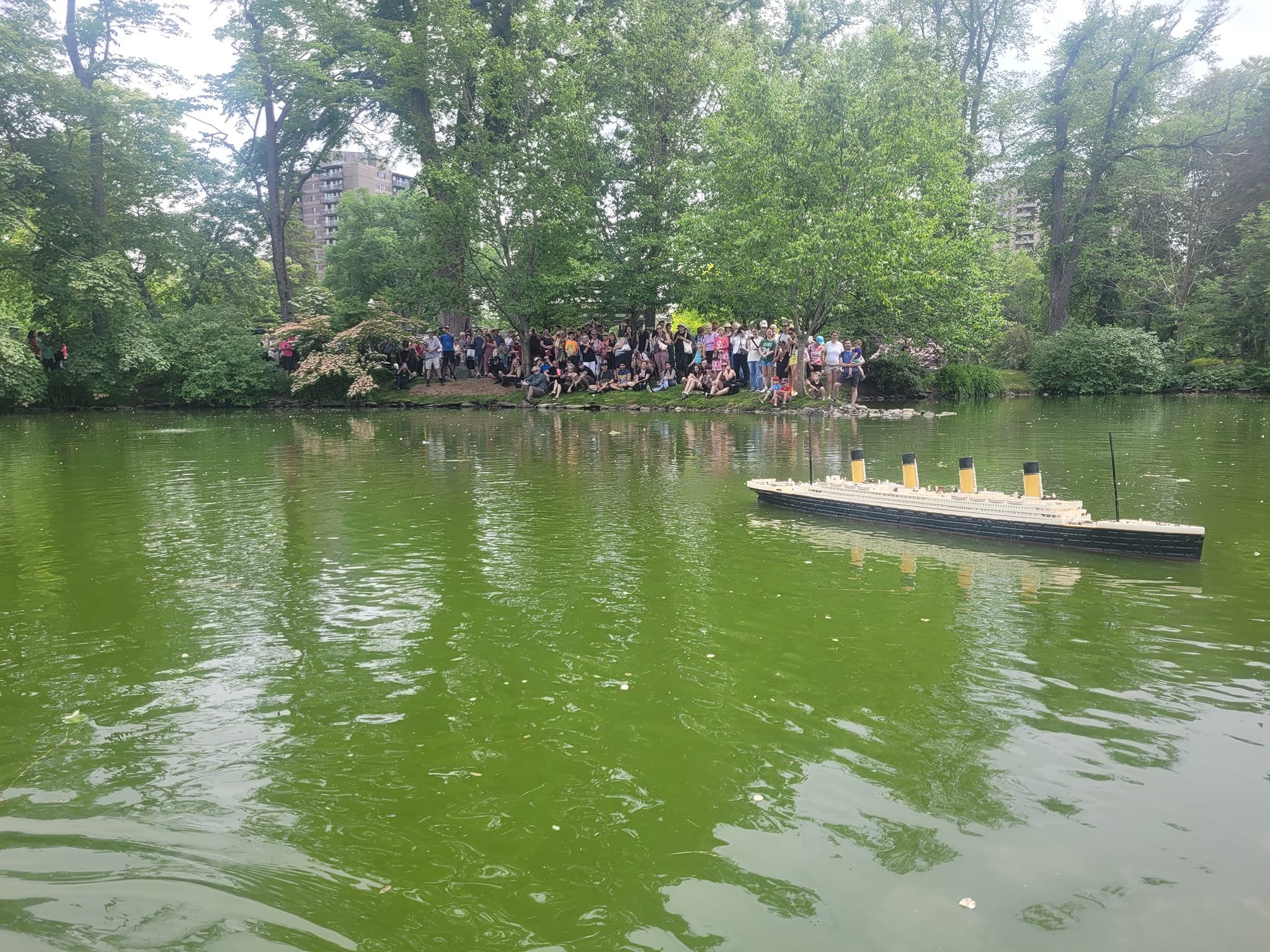
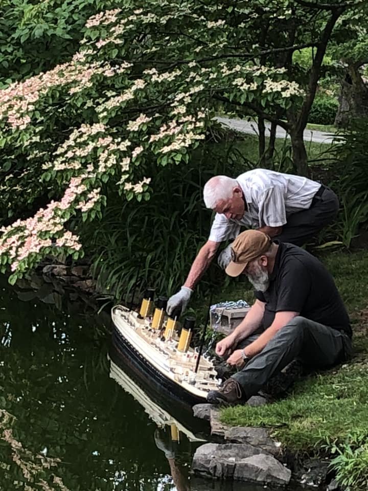
Well, those who have been following me may be aware that my 'building slip' has been filled up with a 1/100 scale model of the RMS Titanic, and the 1/48 scale HMCS St Thomas - which, as of yesterday, have both been launched, and are no longer occupying dry-dock space in my garage. So, that means I can now do a bit of tidying up, and hopefully get back to working on the Bonnie again!! NS
-
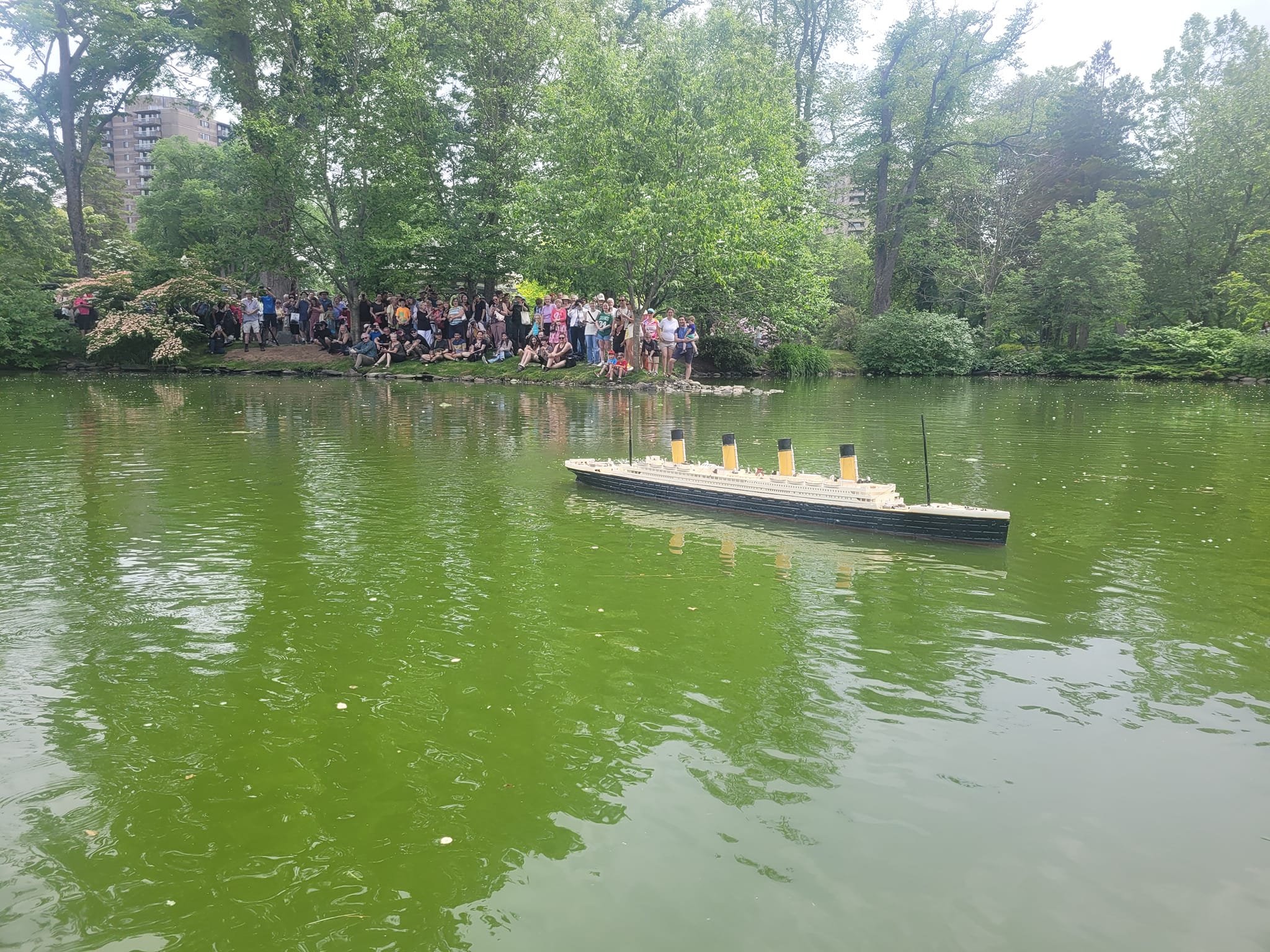
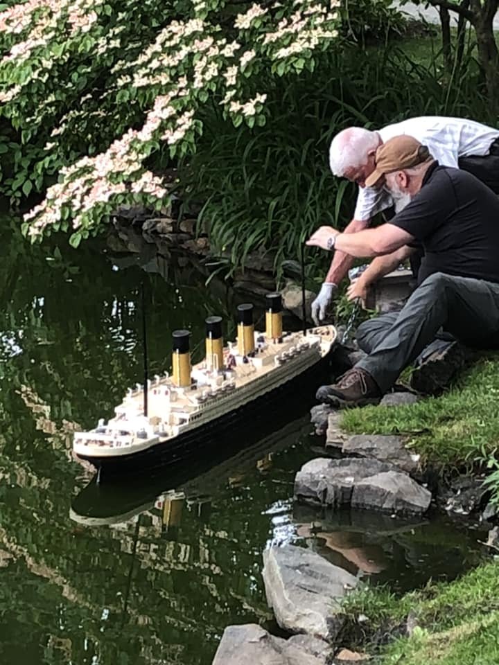
RMS Titanic surfaces again at Halifax Public Gardens | CBC News We got on the CBC as well!!
-
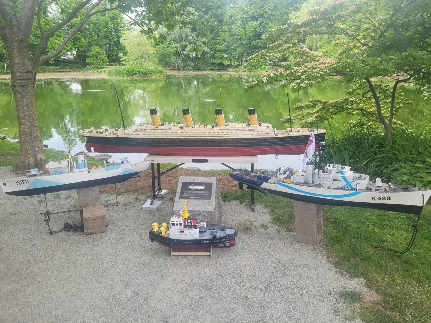
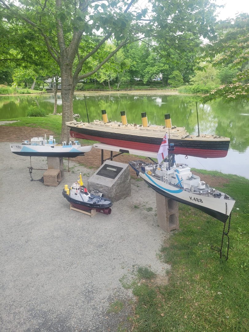
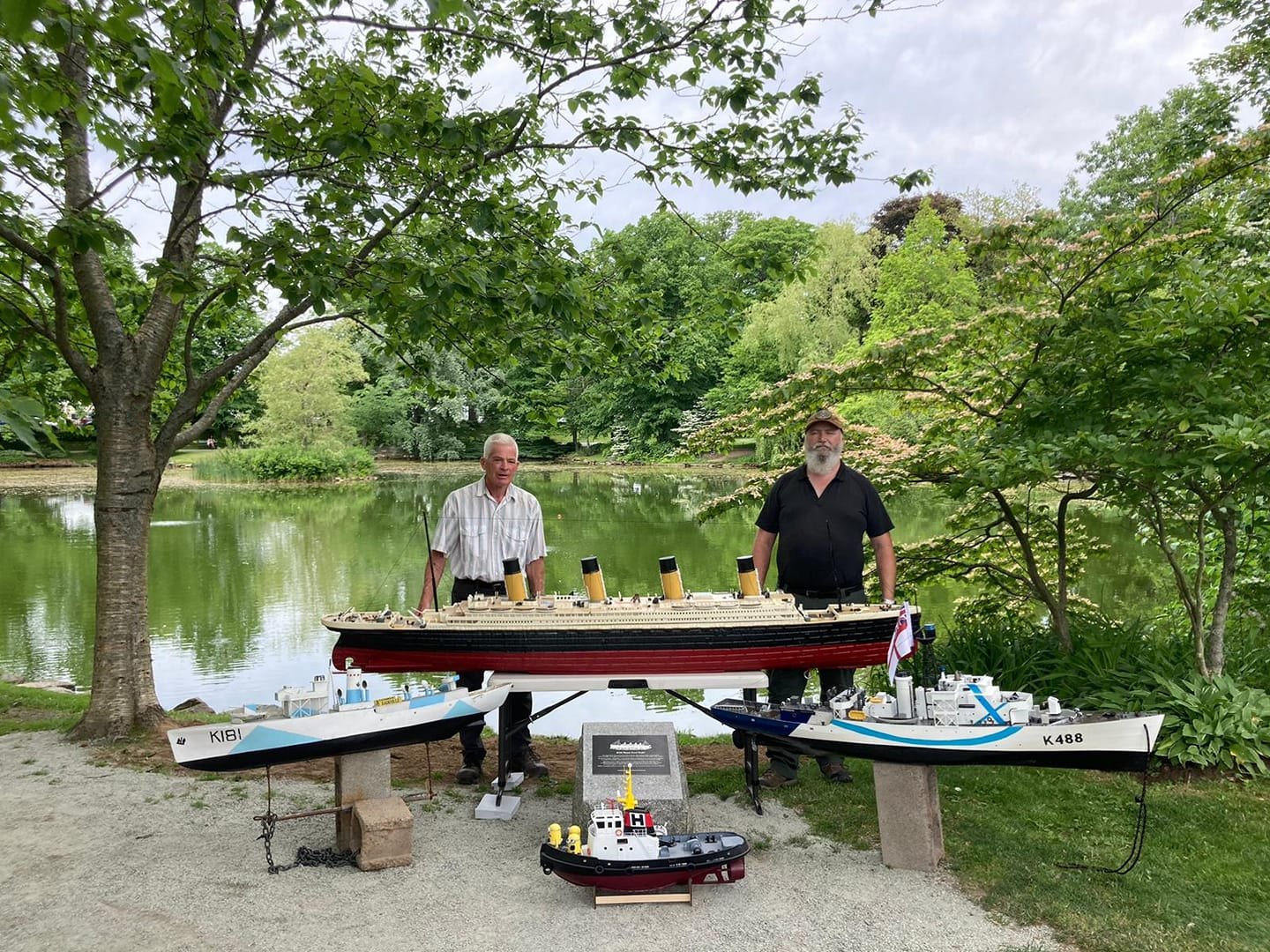
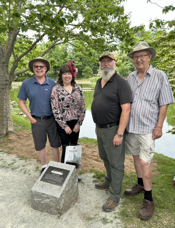
Some additional photos from the launch!
-
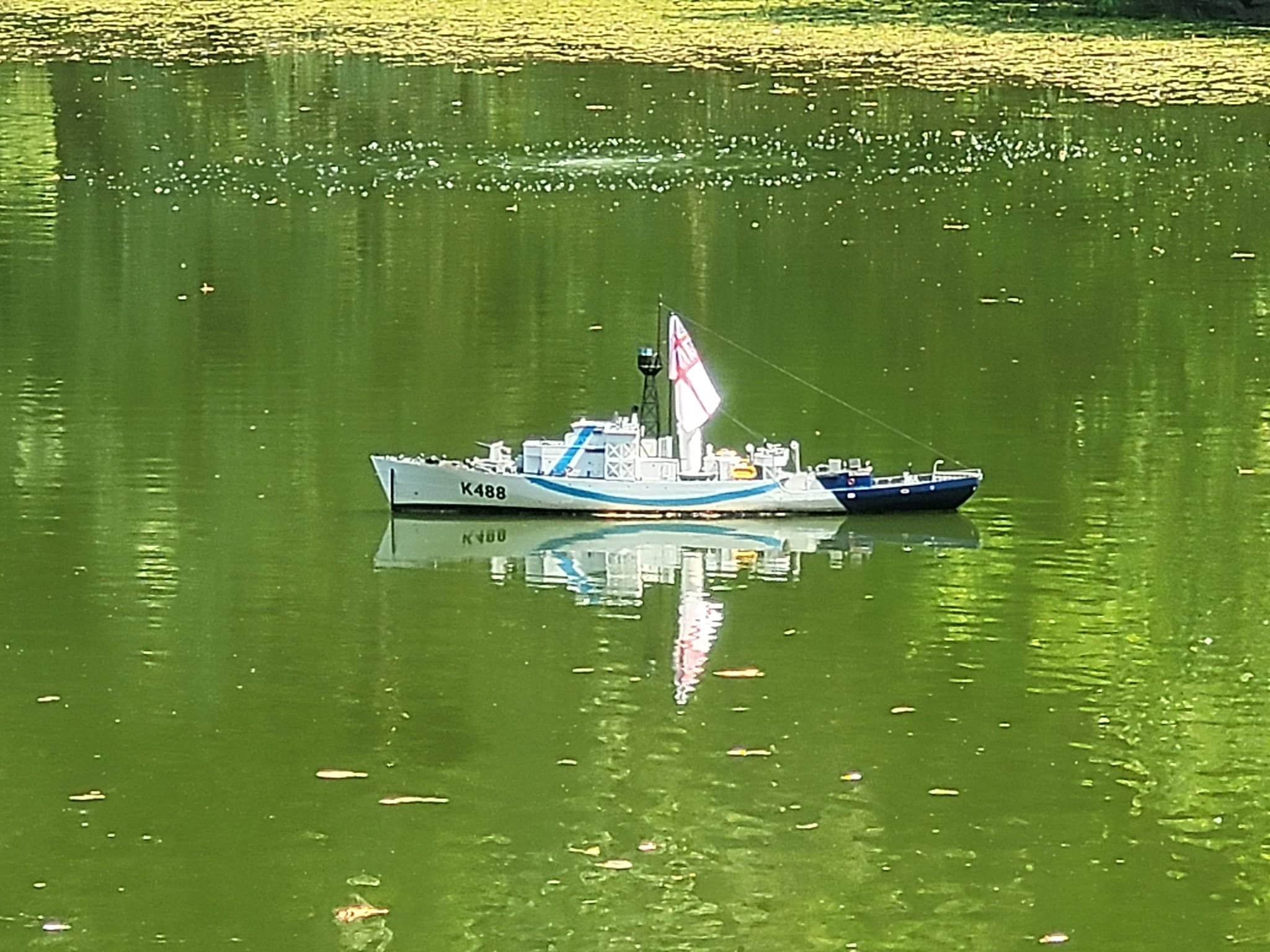
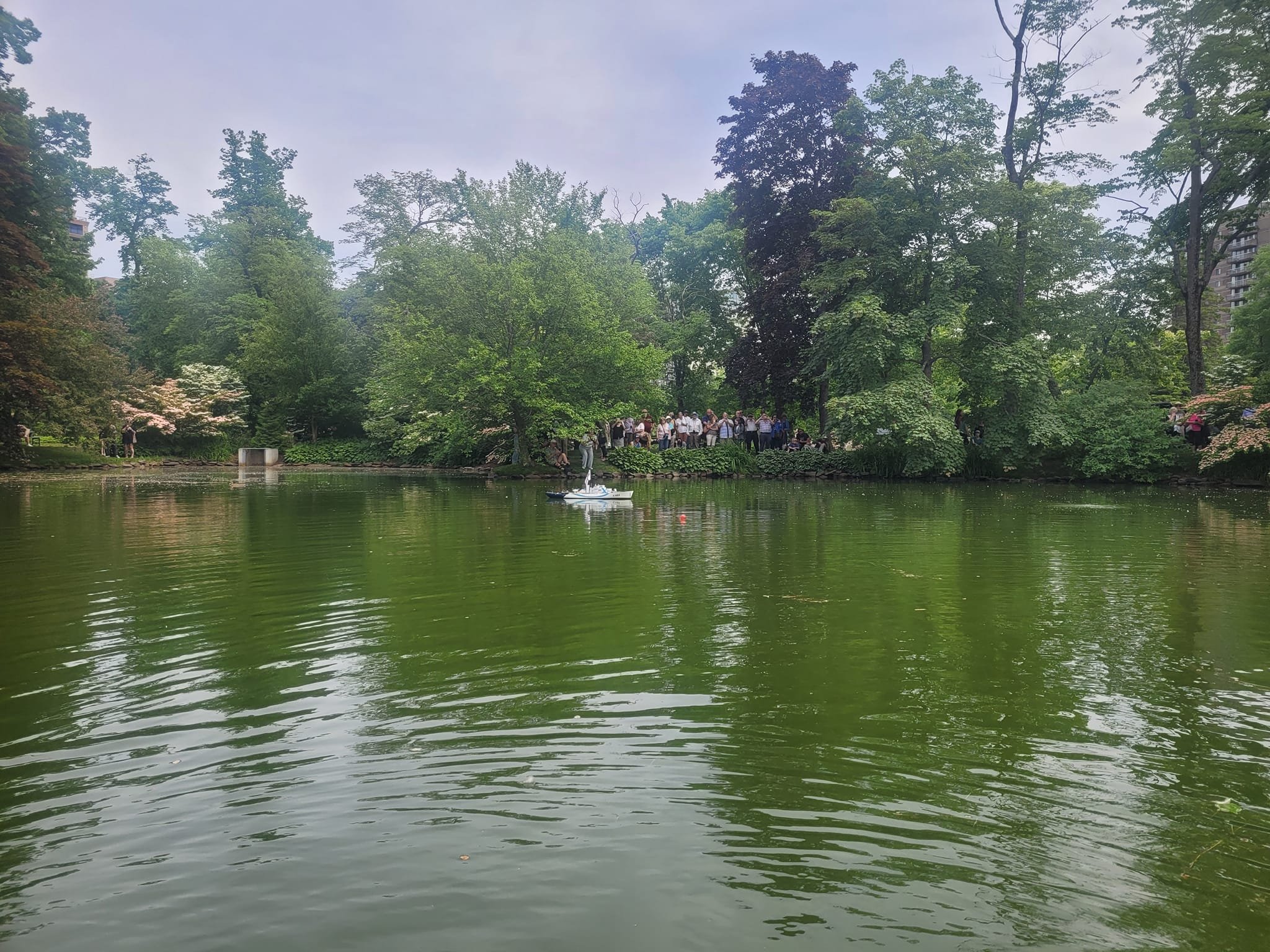
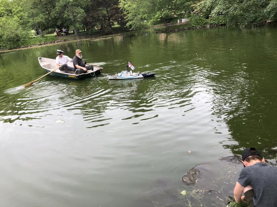
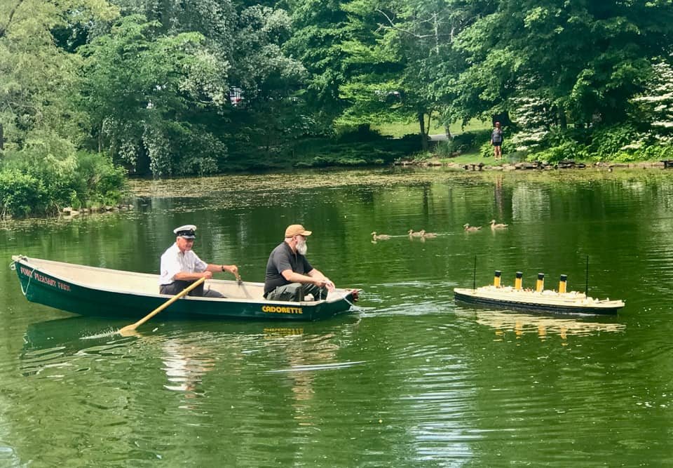
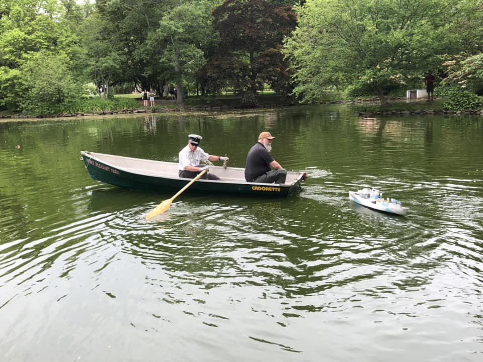
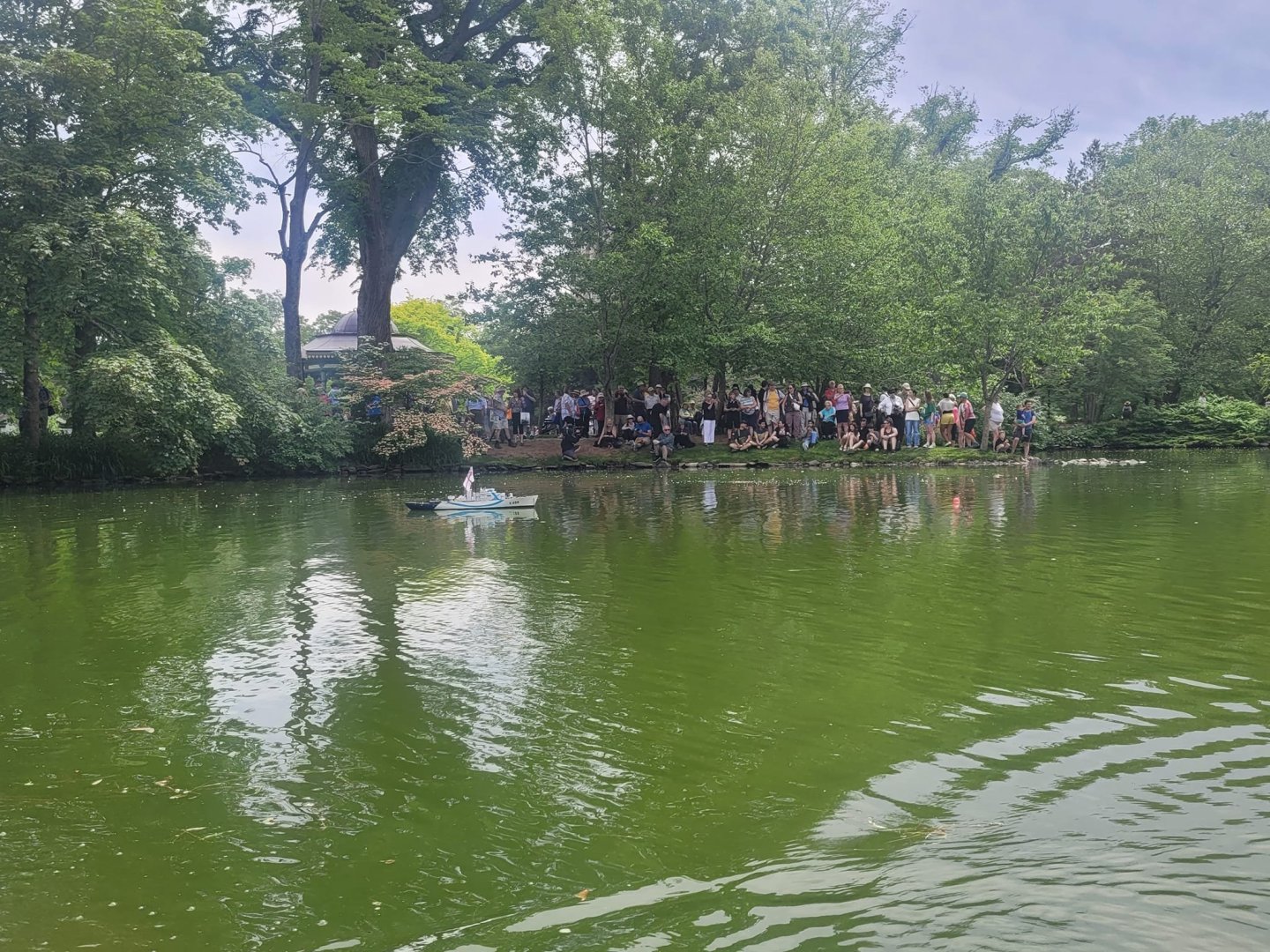
She is now in the pond! Pics of the launch day! She went in along with the old model of Sackville, and our new model of the Titanic! A great time!


-
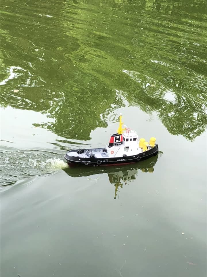
Here are some of the photos I got from today's launch! As you can see, we got the St Thomas in the pond as well, along with the old model they had of the Sackville. I ended up sending the tug out for a quick spin, it was a great day!


-
And here's the full article: Titanic model returning to Halifax Public Gardens | CTV News
-
Local media posted this up today: https://atlantic.ctvnews.ca/photo-galleries/3d-model-of-the-rms-titanic-1.6936136?__vfz=medium%3Dsharebar
-
Absolutely! Should be going live Friday we hope!
-
Saturday's launch is approaching! Last night I did the 'stuff the hull with foam' part of the build. This morning, I met with a local reporter for a short interview about the build and the launch. I forwarded her the link to this build thread, and she's read through it with some intent to steal (with permission) some of the pictures and details. Turns out these threads can be useful!
-
We've got a confirmed date and time for the launch! Saturday the 22nd of June at 3 PM at the Halifax Public Gardens! If you're interested, drop on by to watch! NS