
NavyShooter
-
Posts
693 -
Joined
-
Last visited
Content Type
Profiles
Forums
Gallery
Events
Everything posted by NavyShooter
-
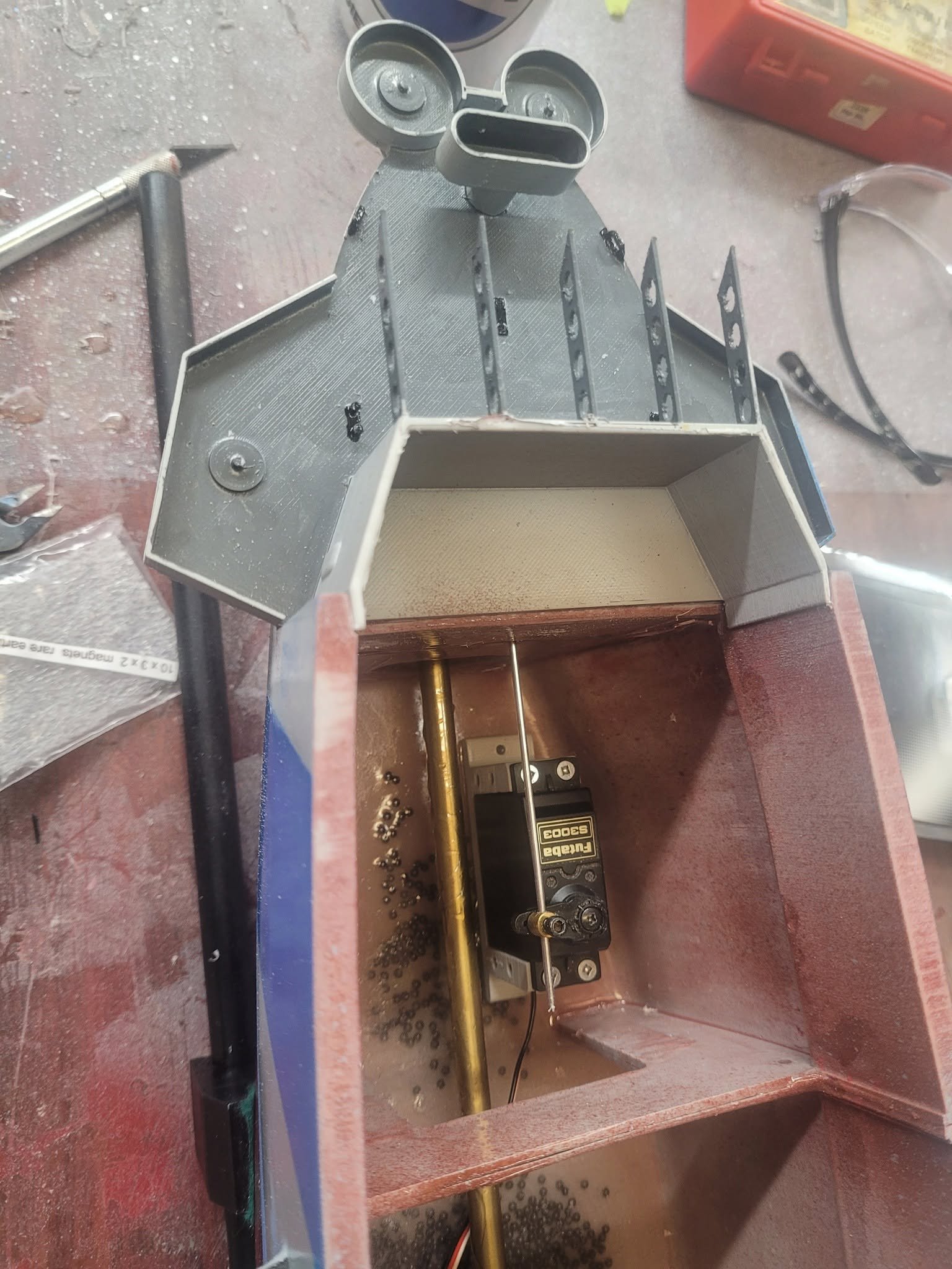
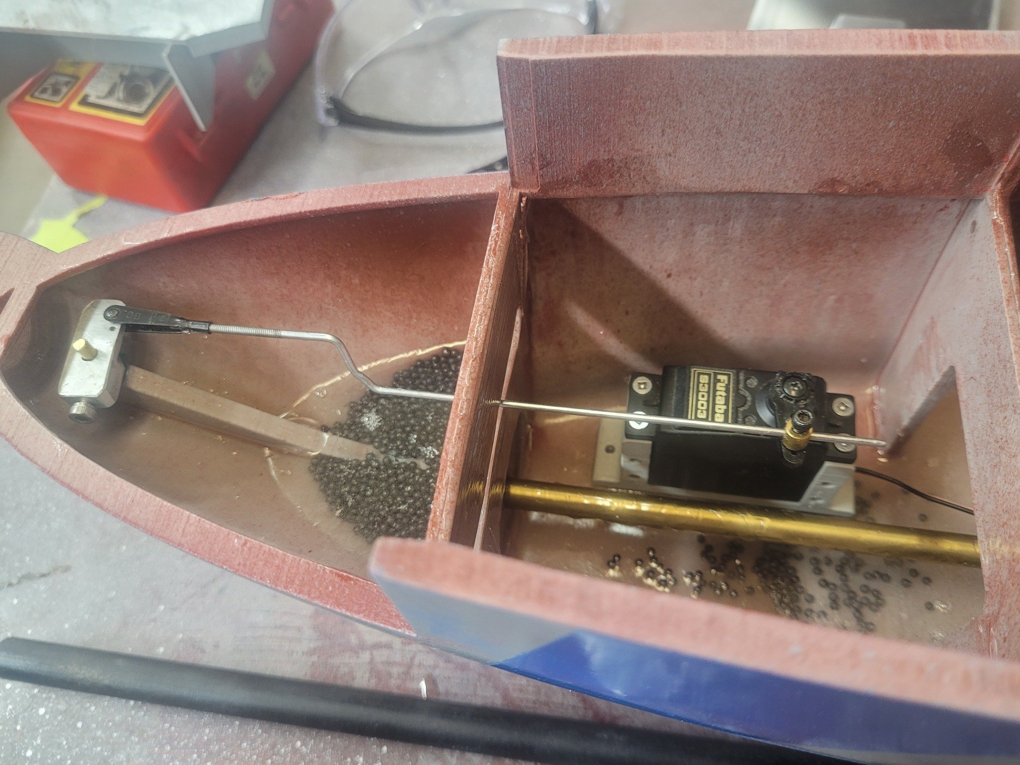
 After a long series of delays - finishing a model of HMCS Sackville and refurbishing a model of Titanic, and then a spell of vertigo (who knew I had rocks in my ears?) I am now back to the grind with HMS Puncher. Here's the rudder system fitted up, and the quarterdeck section has been setup with magnets to hold it in place when assembled. Tomorrow I will try and get the motor mount built, solder on the motor connectors, and see what else I can get done.

- 51 replies
-
- 3
-

-
- Puncher
- escort carrier
- (and 1 more)
-
And, now that my ship-yard has 13+ feet of ships cleared out of it, I'm going to be able to start thinking about my own models again!!!
-
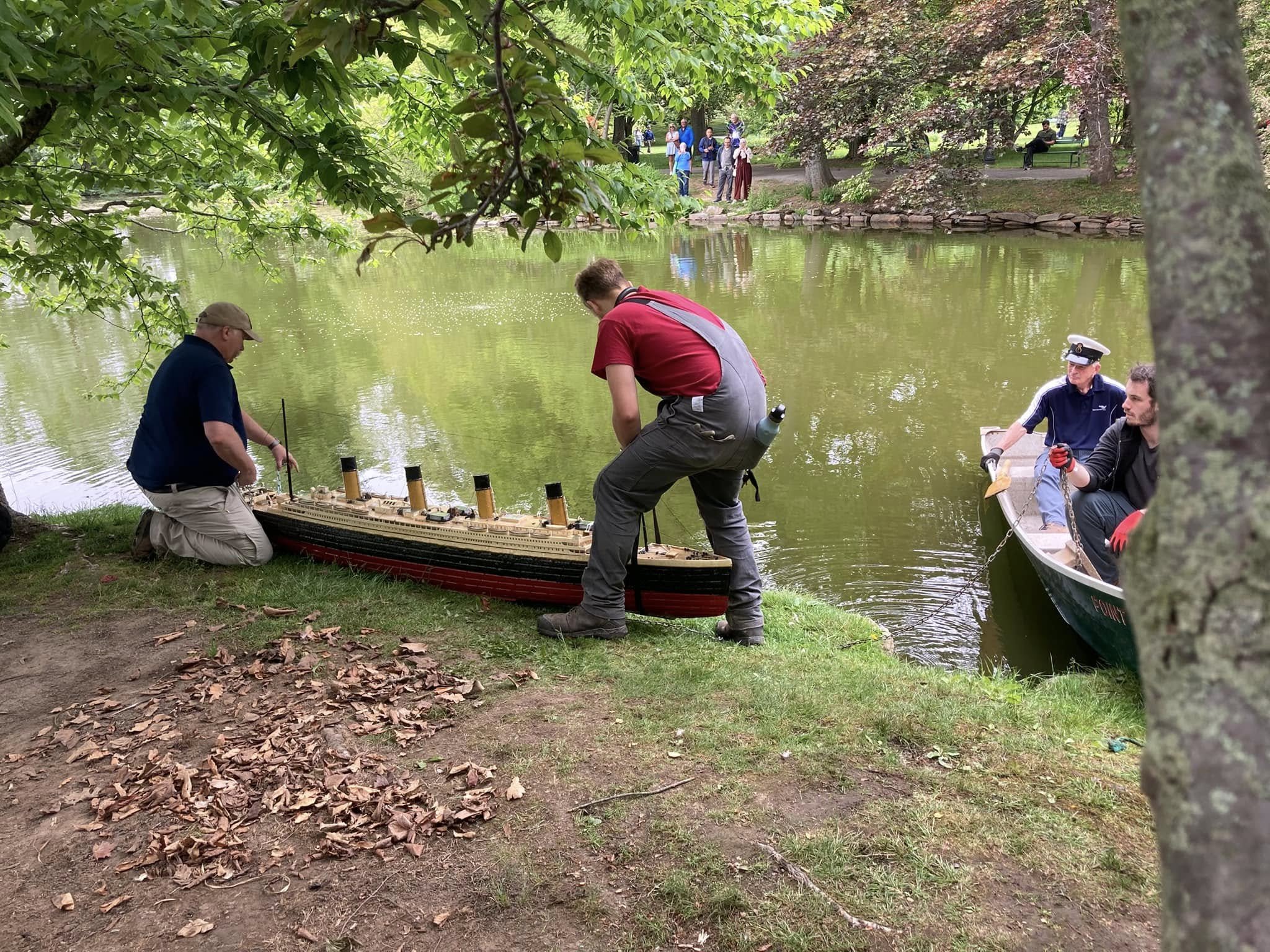
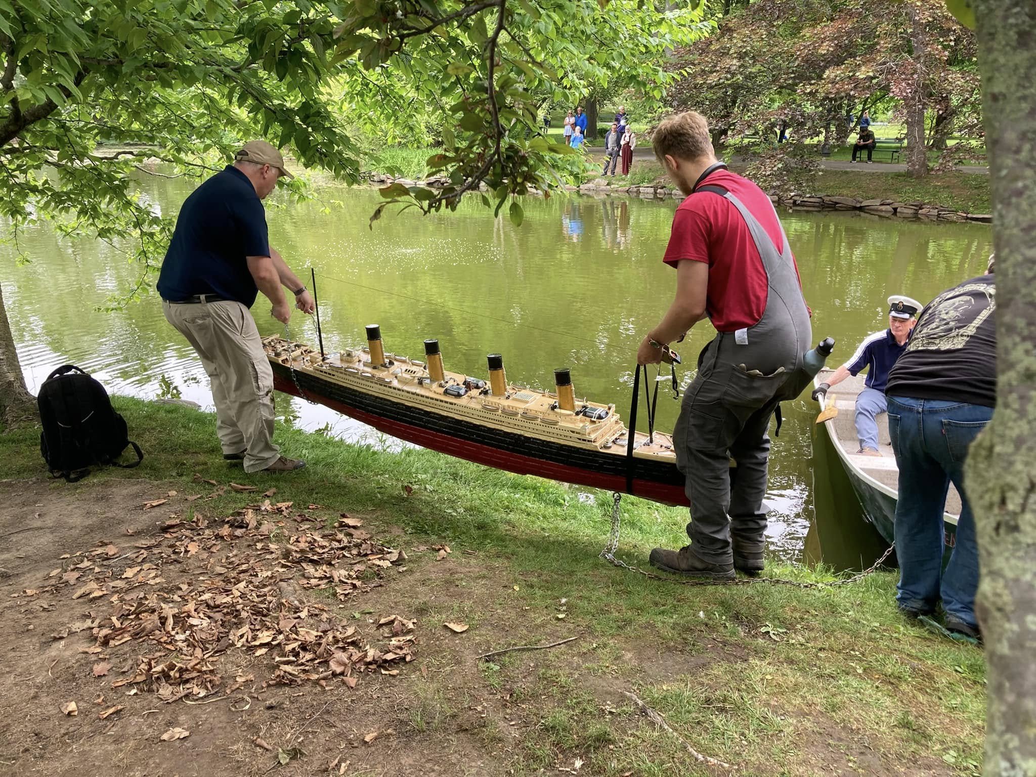
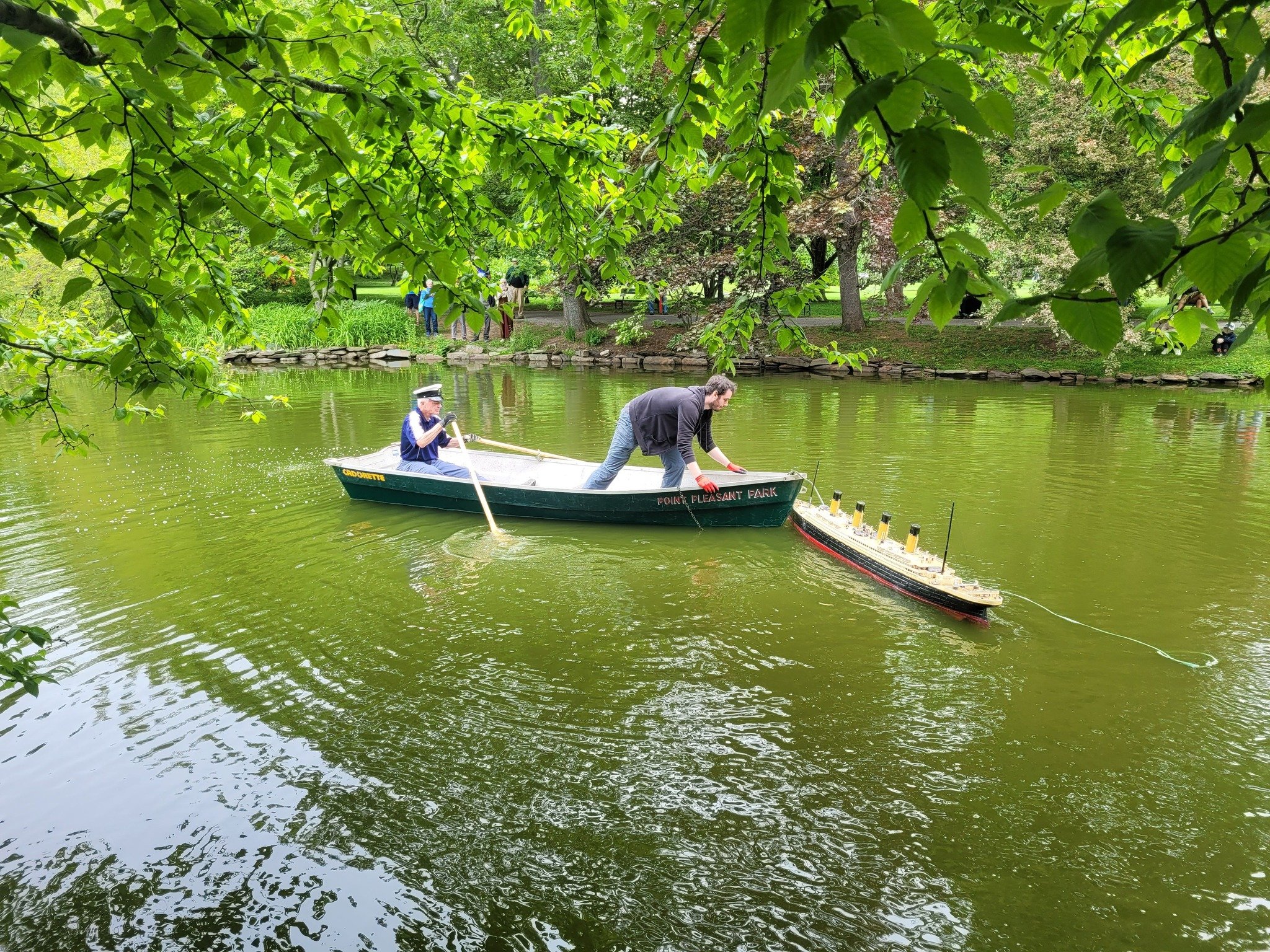
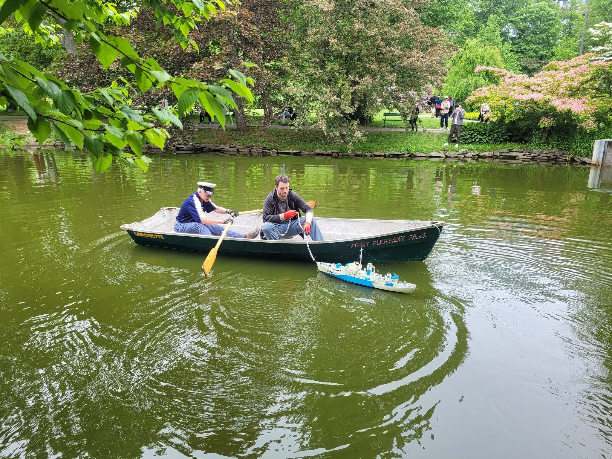
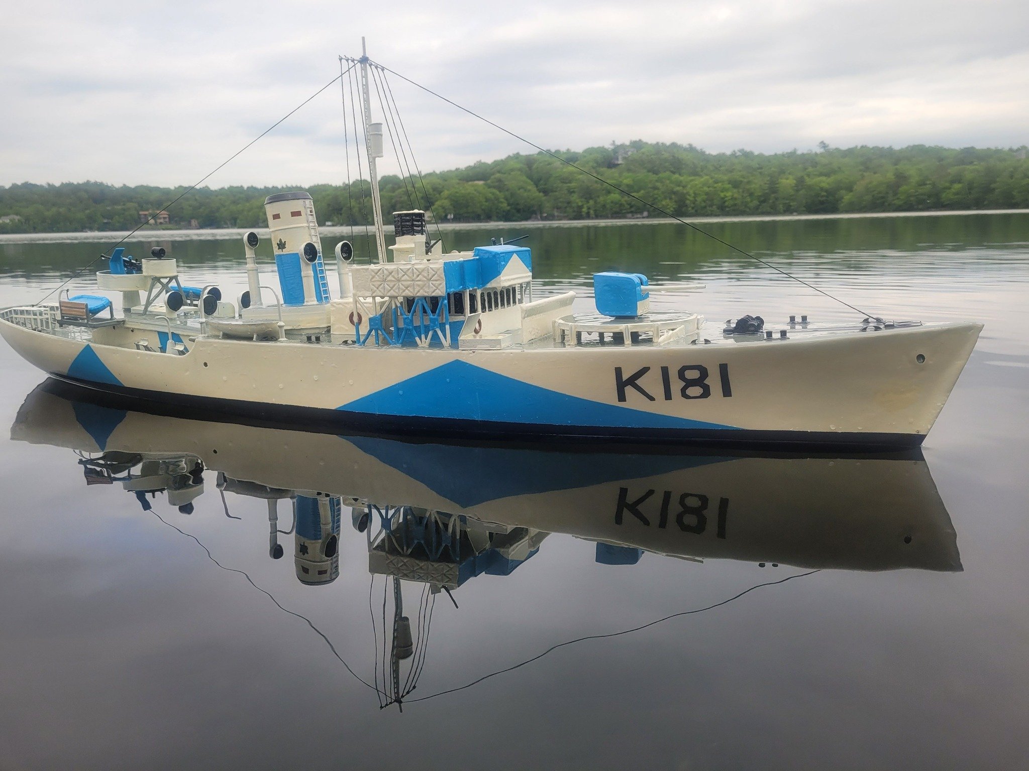
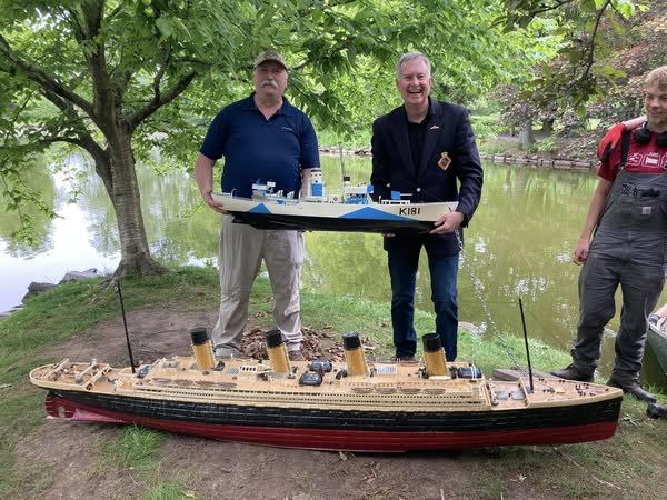
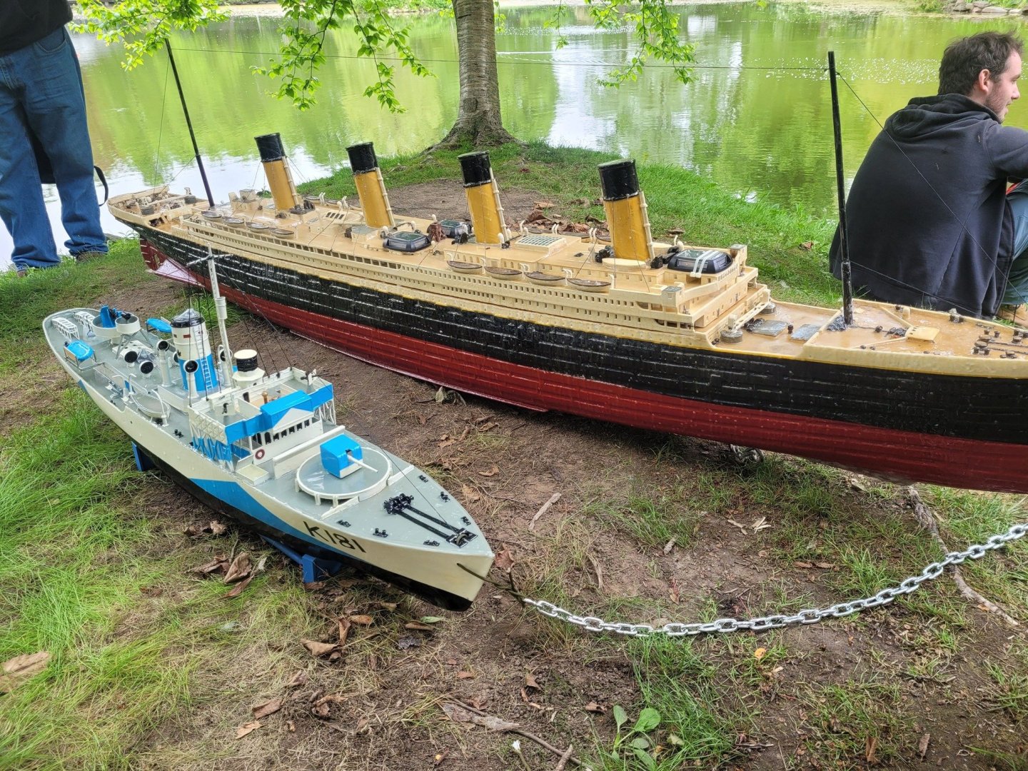
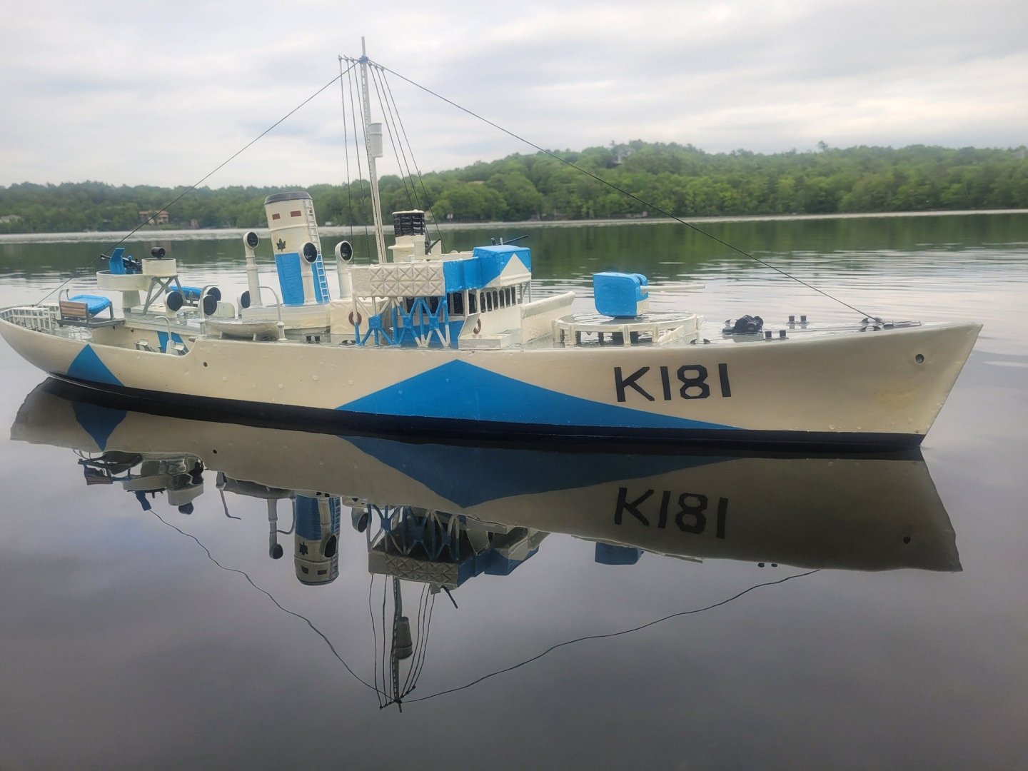
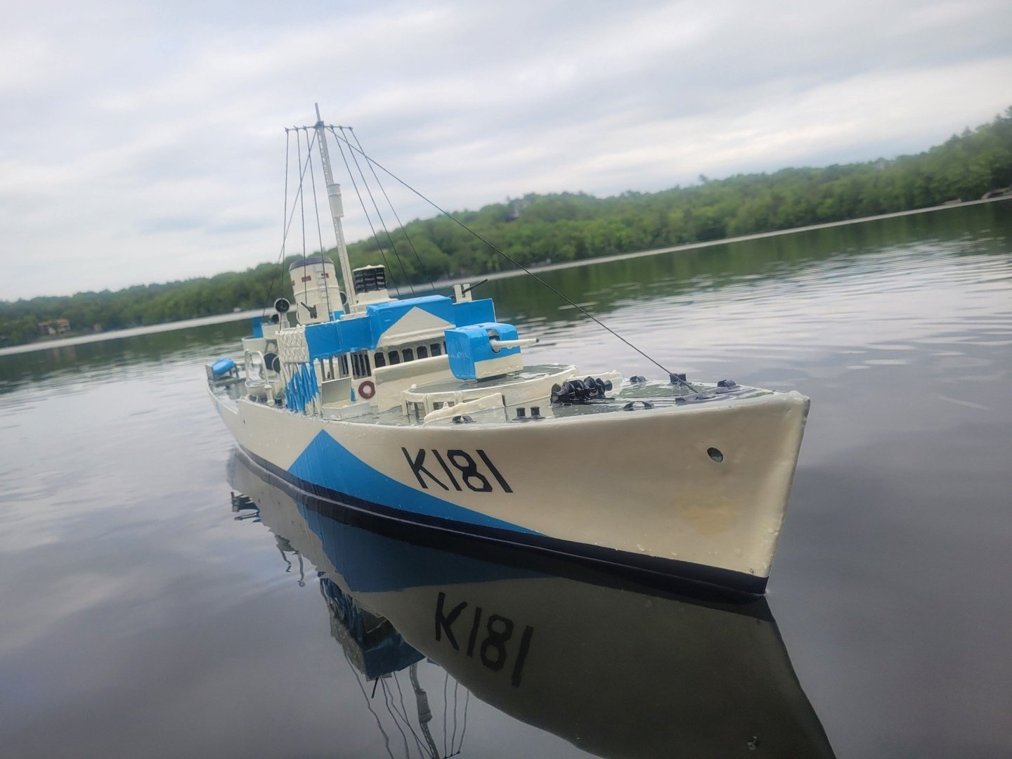
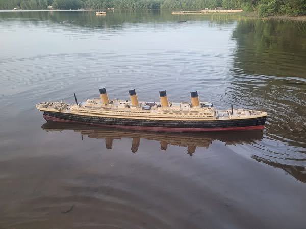
Titanic and the new Sackville model have been launched into the Halifax Public Gardens for the season! I forgot to factor in the weight of the anchor chain on Sackville when I ballasted her, so she's showing as down by the bow just a bit. Oops. In the photo with two people holding the Sackville - I'm on the left, and Mr. Woodburn is on the right - he's the Chair of the Canadian Naval Memorial Trust. The Titanic Society of Atlantic Canada have a function this weekend, so the launch was well attended by them!


-
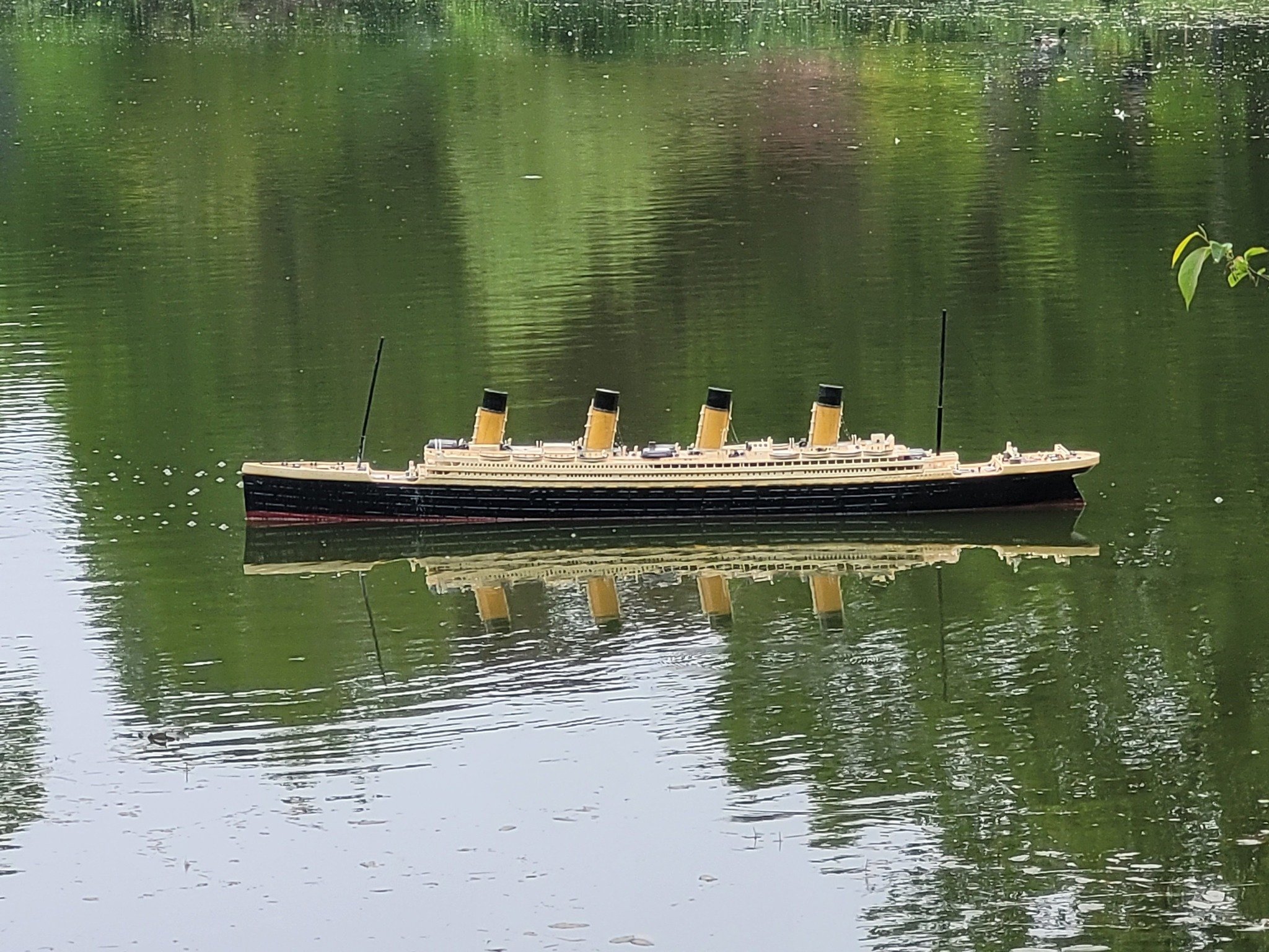
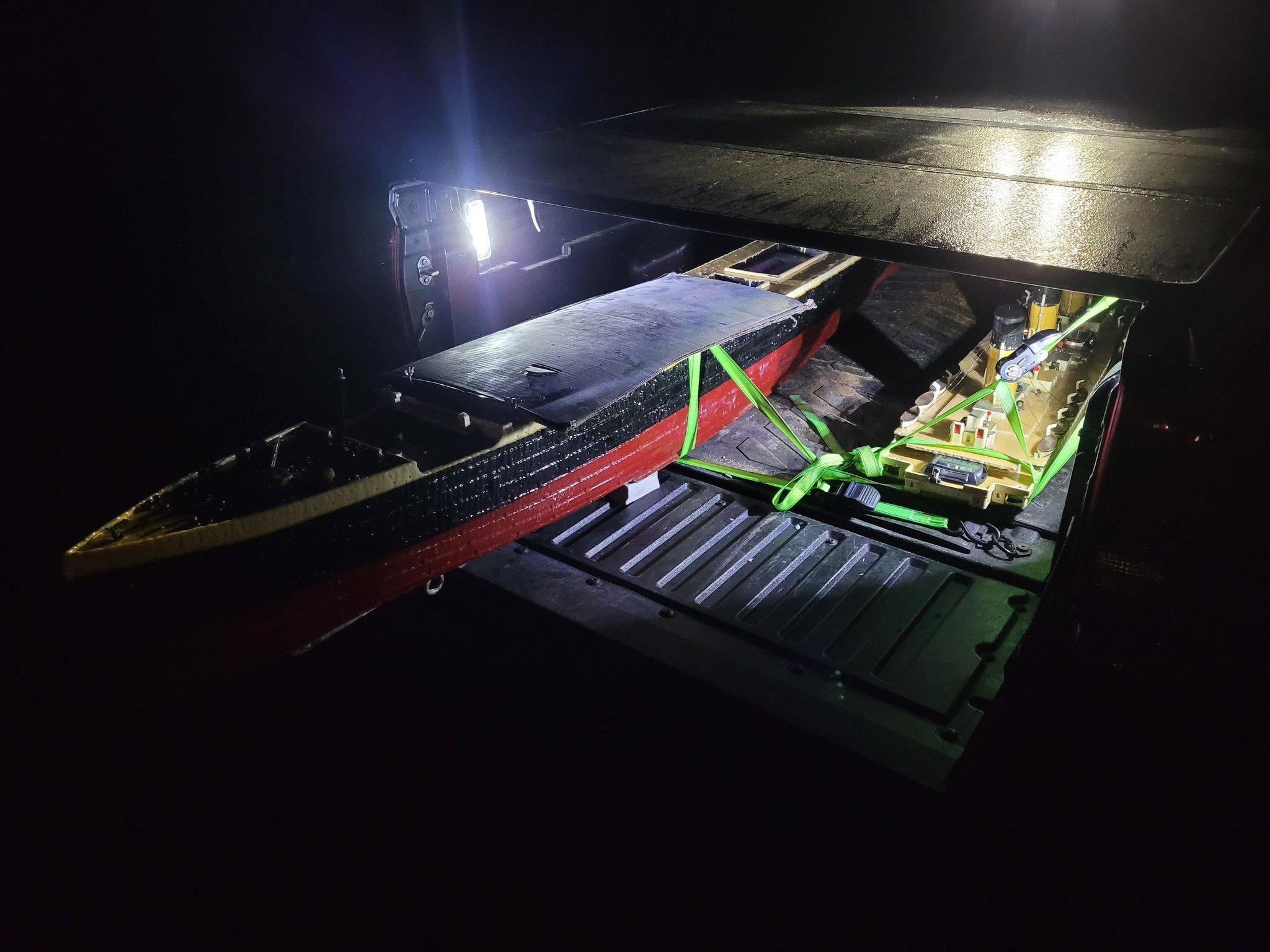
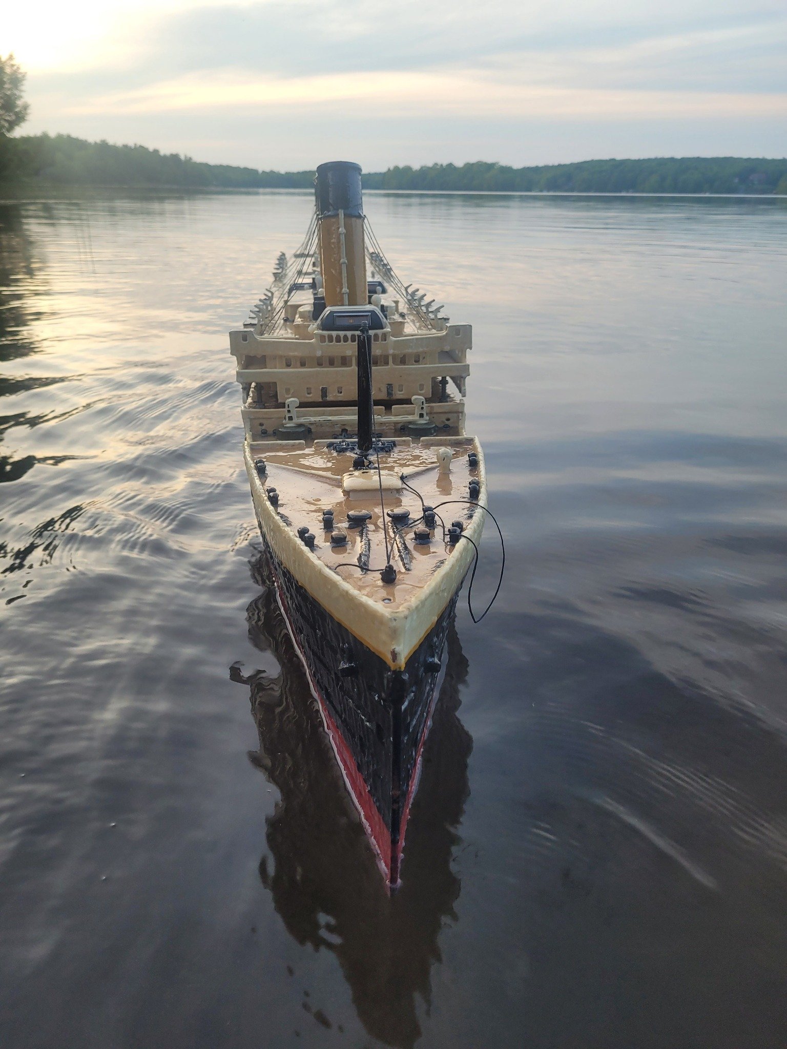
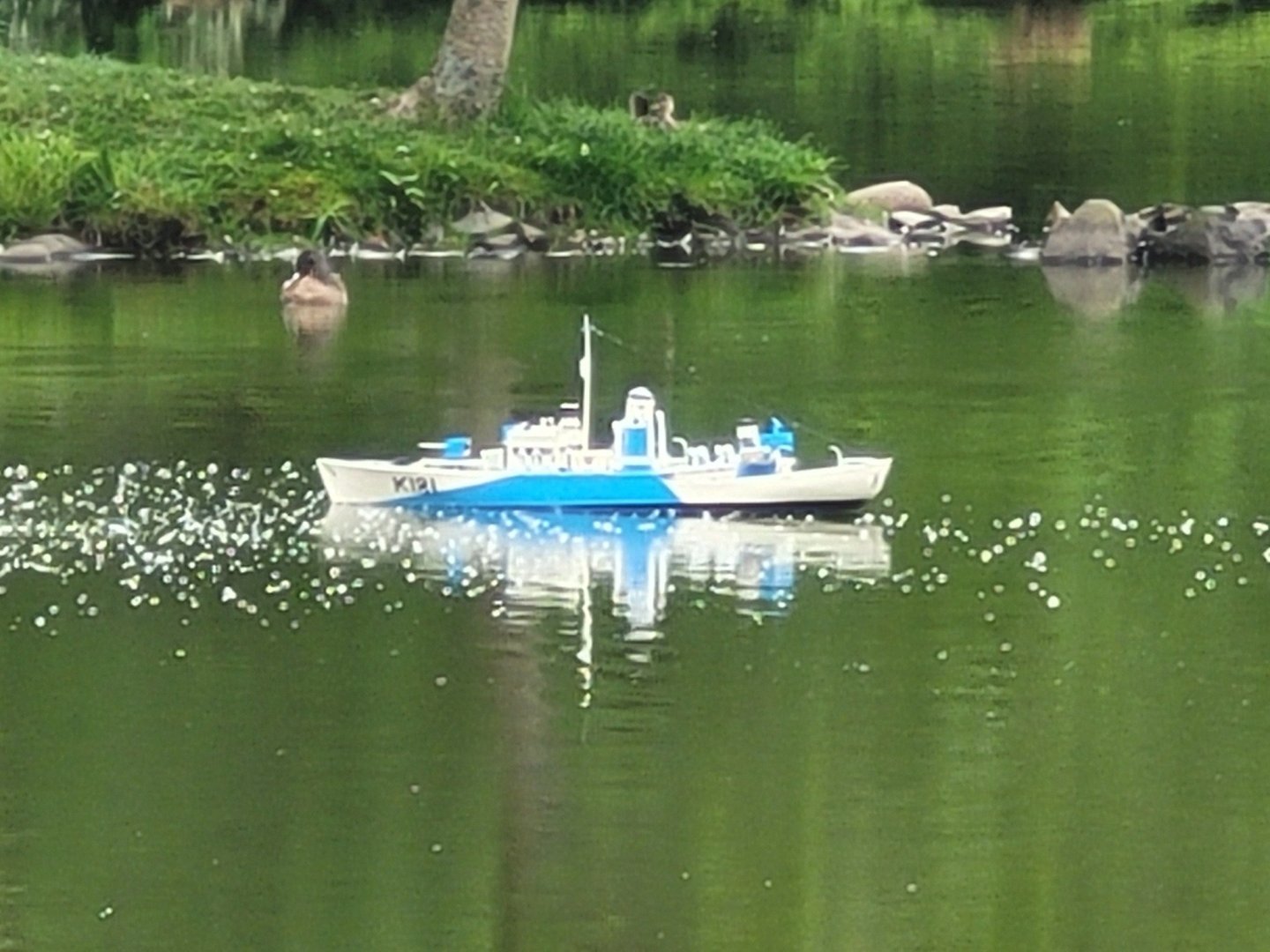
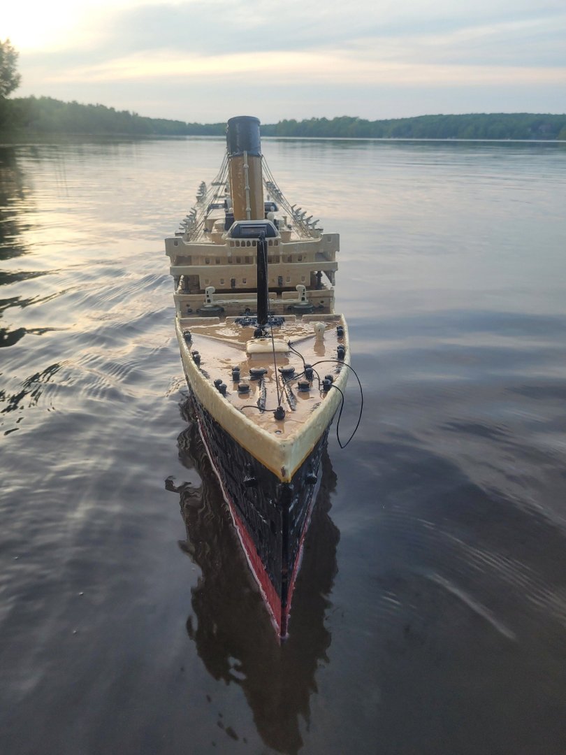
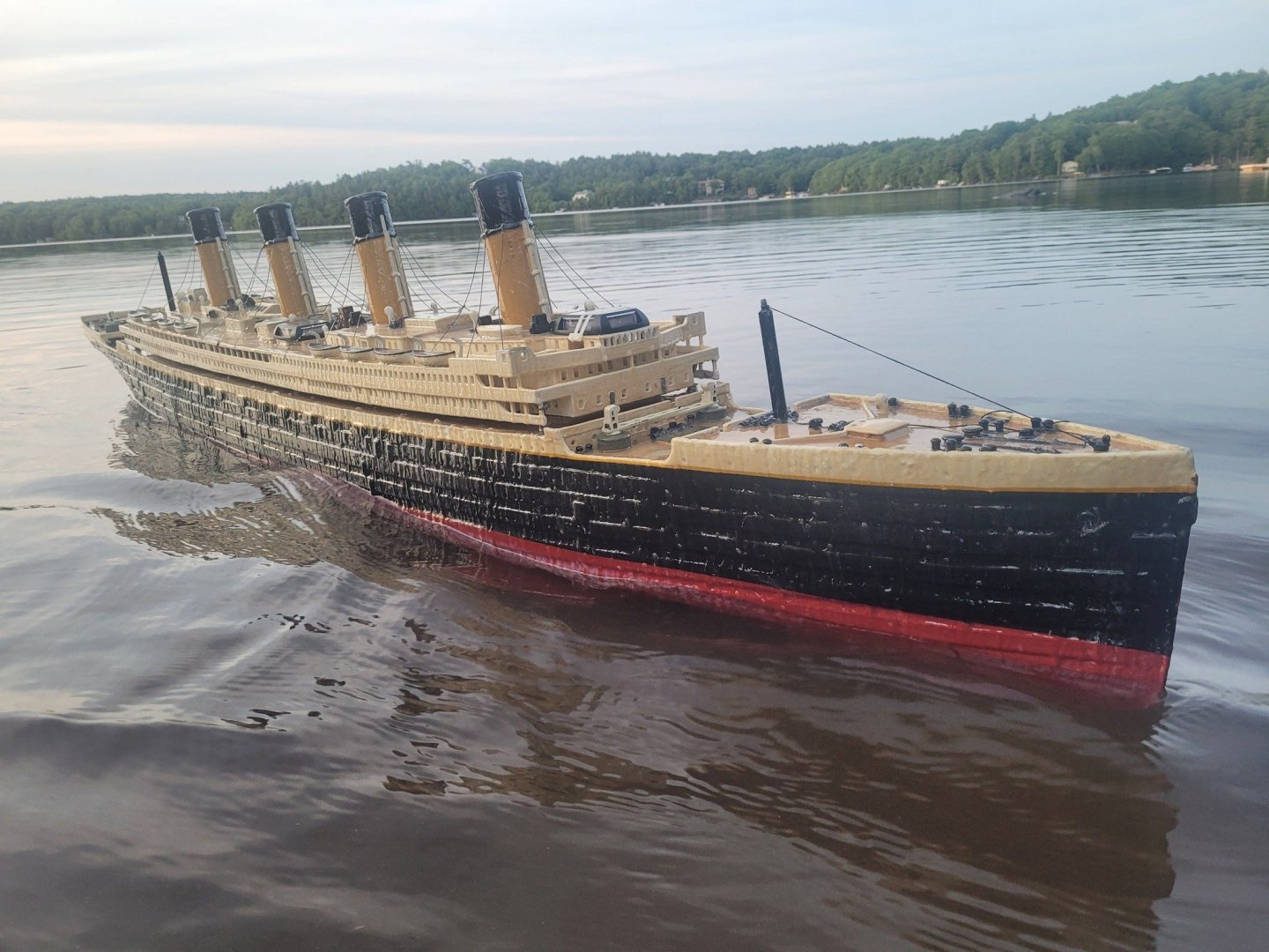
Titanic's test float was last night - ballast adjusted, and I think she's good. Here's some pics, and the new HMCS Sackville model as well. Both are being launched again tomorrow at the Halifax Public Gardens at 1 PM. NS
-
We'll be launching the Titanic again on Thursday at 1 PM at the Halifax Public Gardens! I've redone some of the interior fiberglassing and put a fresh layer of epoxy resin on the entire outside. Additionally, I decided to add some 'puck' lights - so the upper decks will get lit up in the evenings. Pictures will follow!
-
My experience with them was with the RCN on our Halifax Class Frigates - we didn't have the below deck VLS, we had above deck 8 cell VLS packs on each side - the missiles would come aboard with a data pack, and would need to get cycled through the Magazine/Depot every so often as they would do the maintenance ashore. All we had to worry about was hooking up the cables, unlocking the cannisters, and making sure they synched properly with our FC Radars on installation. If that worked, they were good for a while onboard. As Magazine Custodian, I signed for the missiles, torps, and all other energetic 'stuff' onboard...to the tune of over 6000Kg NEQ (12,000 pounds or so). NS
- 54 replies
-
- 2
-
-
- 3d cad
- cleveland class
- (and 1 more)
-
A true labour of love here - well done on the 3D modeling. The complexity of the Talos missile system is fascinating. Having sailed on ships with VLS, it certainly makes me understand why they transitioned from the Talos to the VLS. The simplicity of systems for a cannister based missile system makes it so much easier to maintain. NS
- 54 replies
-
- 2
-
-
- 3d cad
- cleveland class
- (and 1 more)
-
Here's a video that talks about it a bit. Option 13 for the PWM frequency will set it to higher frequencies - ideally go with the 16KhZ which is almost beyond the audible range, and makes it effectively silent!
-
Suggestion - if you go with a Hobbywing 1080 ESC, you can adjust the internal frequency that they operate at - when operated at lower frequencies, they 'whine' like most ESCs do. If you adjust the Freq to the higher end, the ESC whine effectively disappears. I've got a video somewhere about doing that...let me dig up a link. I don't know if your 1060's are able to be programmed the same way.
-
Looking at your results with those, I'll suggest trying a 0.25mm nozzle with your FDM and slow down your printing speed a bit - you'll end up with a finer bit of detail, and a nicer finish. The funnel and vents may turn out OK!
-
I'm not a railroad guy, but damn....this is beautiful work. Your subject matter is interesting, and the history that all of this ties together is amazing...from the tales of how grain elevators worked back in the day to your leaf grinding...wow! Definitely following this thread going forward! Great work! NS
-
I came across this site a while back talking about WW2 Royal Navy Ship's boats: Royal Navy Ship’s Boats of WWII – On The Slipway And, if you're looking for some minimally detailed ship's launches, here's a site that may help: (you may have to sign up for this forum to access them though) RN Steam Launches | R/C Warship Combat Ship's boats and liferafts | R/C Warship Combat
-
Welcome aboard! What part of the world do you live in? NS
-
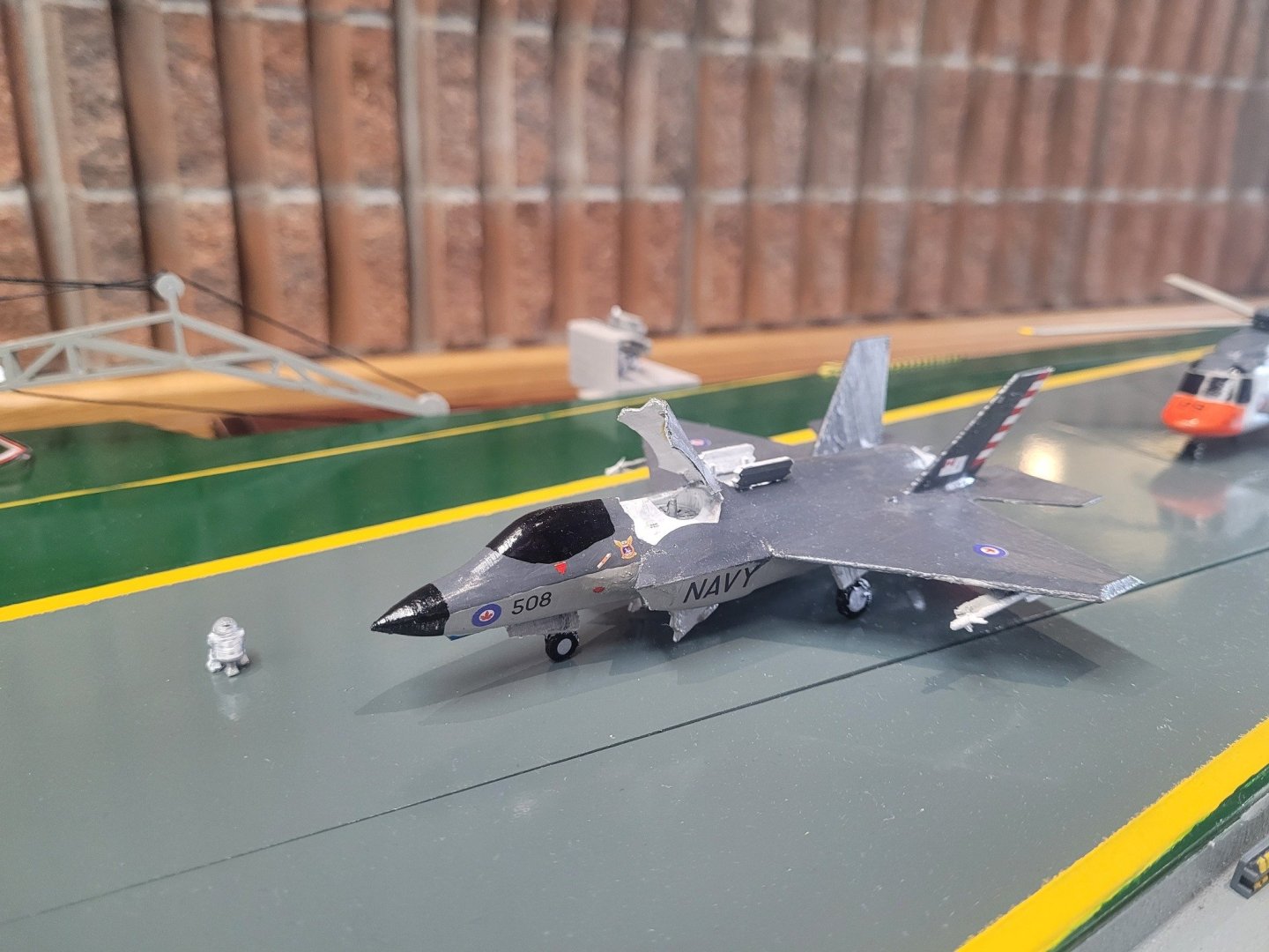
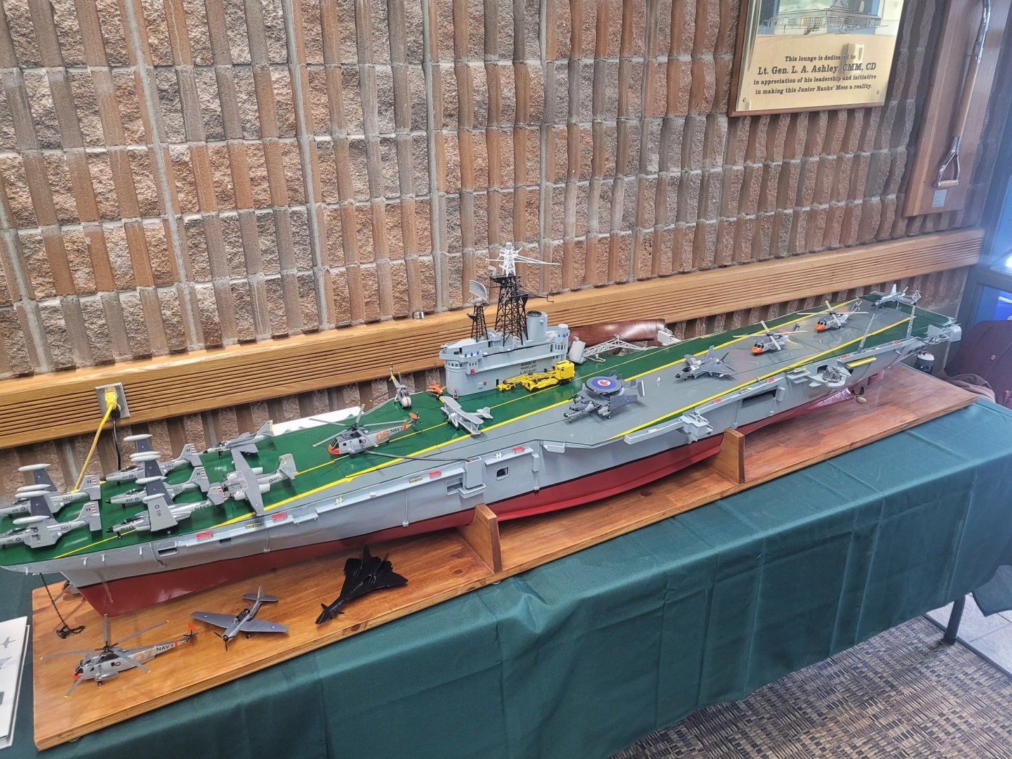
The verdict about what I was able to get done in a week was - not much - I was sick in bed for most of 3 days. Ended up with this for presentation - no - some of the aircraft ain't right - no - I don't care. It was done specifically to tweak some Air-Force types who were visiting to have a look and we had a good laugh about it. 🙂
-
Very nicely built! The ropework is well done!!
-
Gorilla Glue applied...weights holding the deck down...we'll see how it looks tomorrow.

-
She's been on the shelf since December - hobby show in a week - wonder what I can get done on her this week in advance of the show?
-
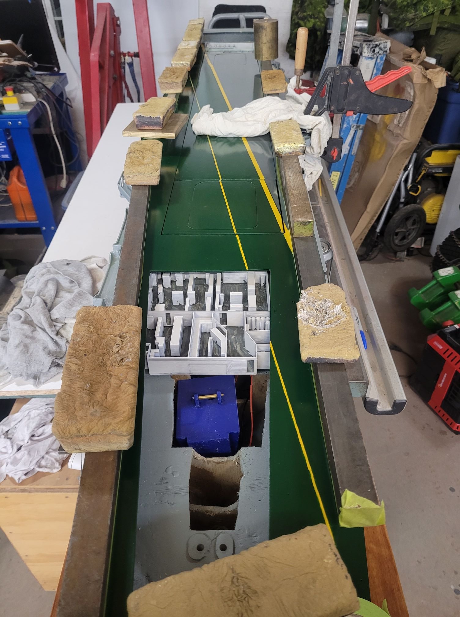
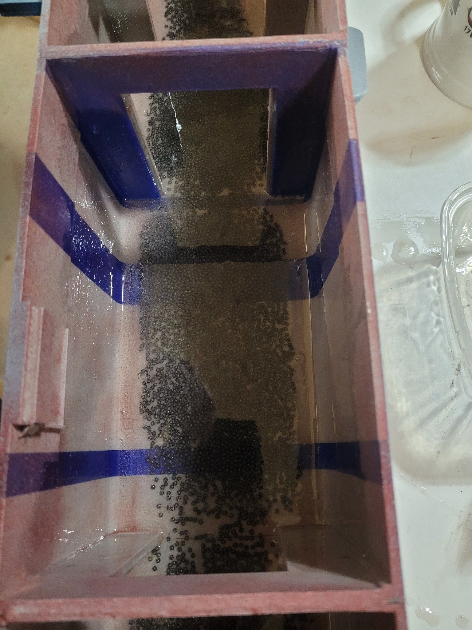
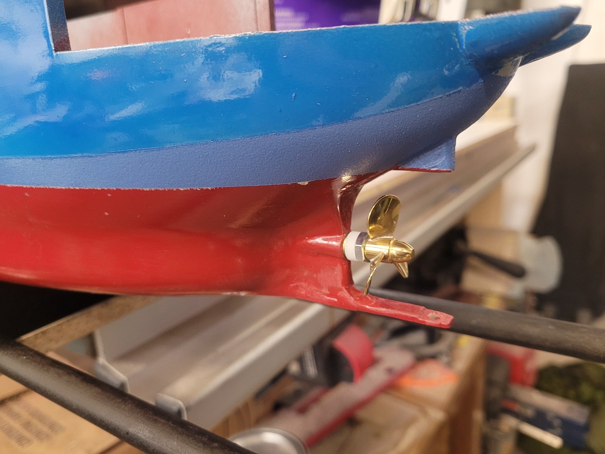
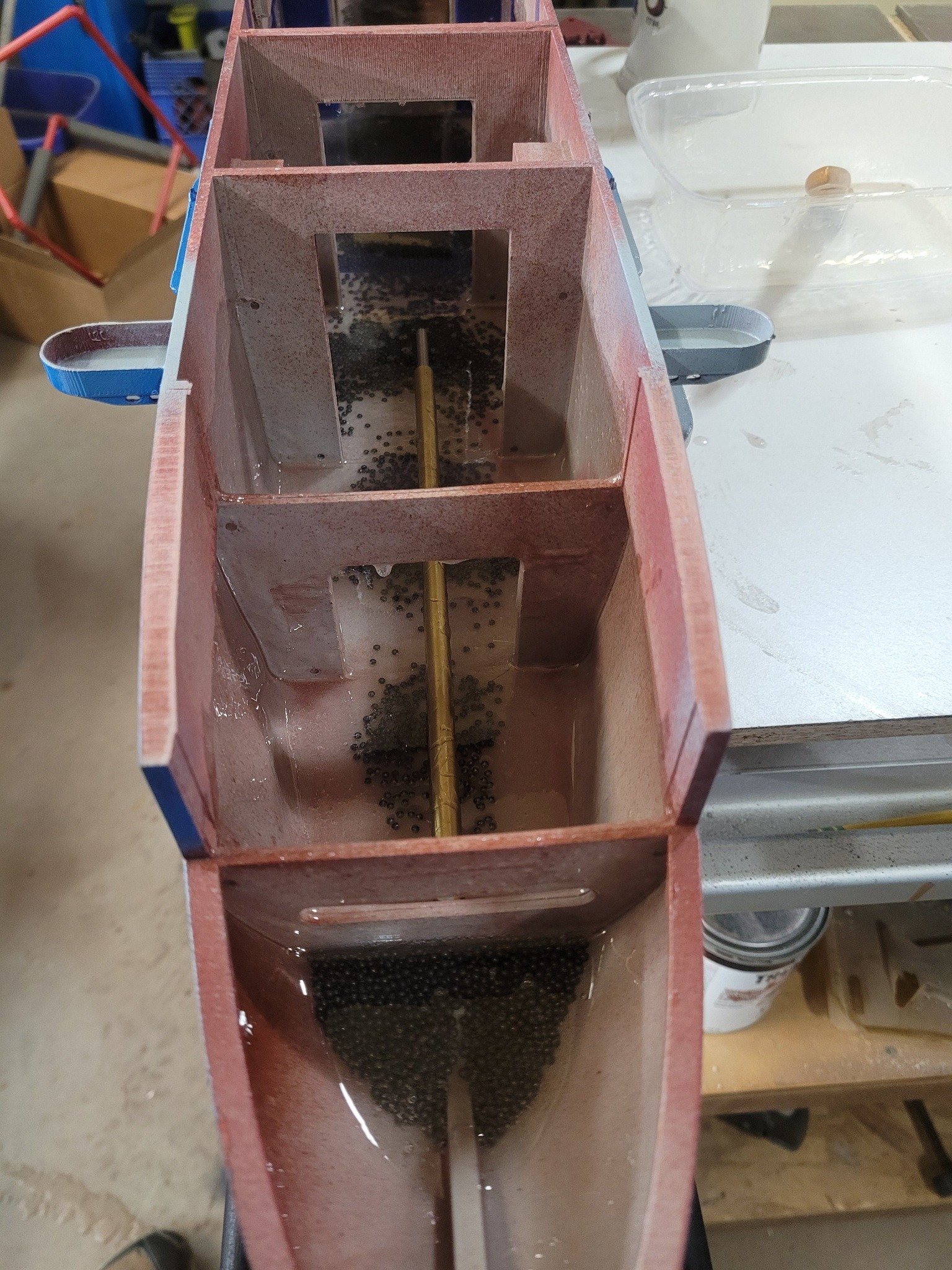
Some further progress on HMS Puncher - shafts didn't arrive from the prop-shop in the UK, and Simon has gone radio silent, so I'm guessing I've wasted my money there....so I got some Dumas hardware that fit the bill. A bit long on the interior side, but it was the right diameter stuffing tube, and the right diameter prop, so yeah, here we are. Also, doing some epoxy work on the St Thomas and had a bit of left-over resin, so I poured in a pound of lead shot and epoxied it into place along the length of the keel. We'll see how she looks next weekend at the Shearwater Aviation Museum hobby show!


- 51 replies
-
- 3
-
-
- Puncher
- escort carrier
- (and 1 more)
-
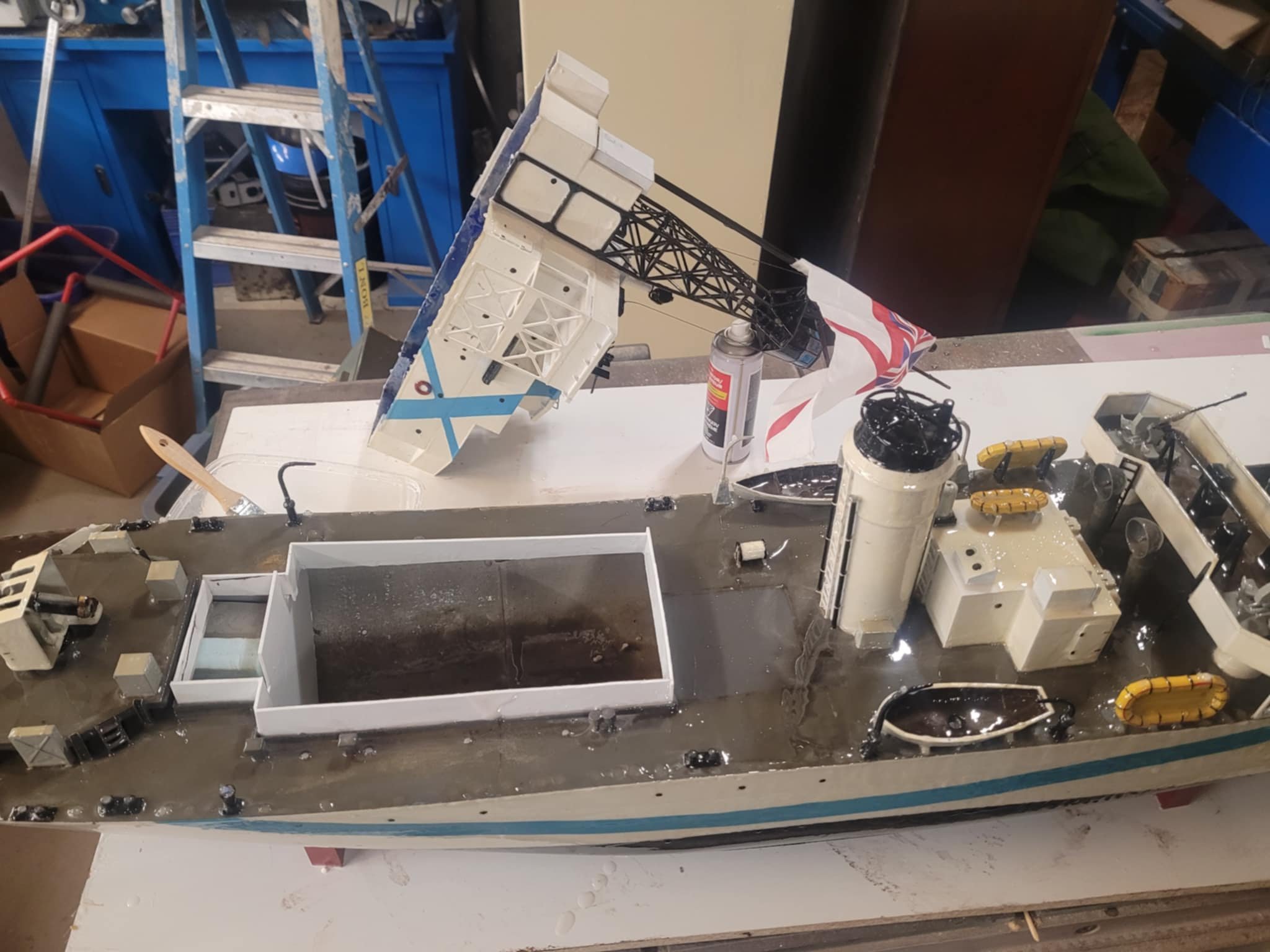
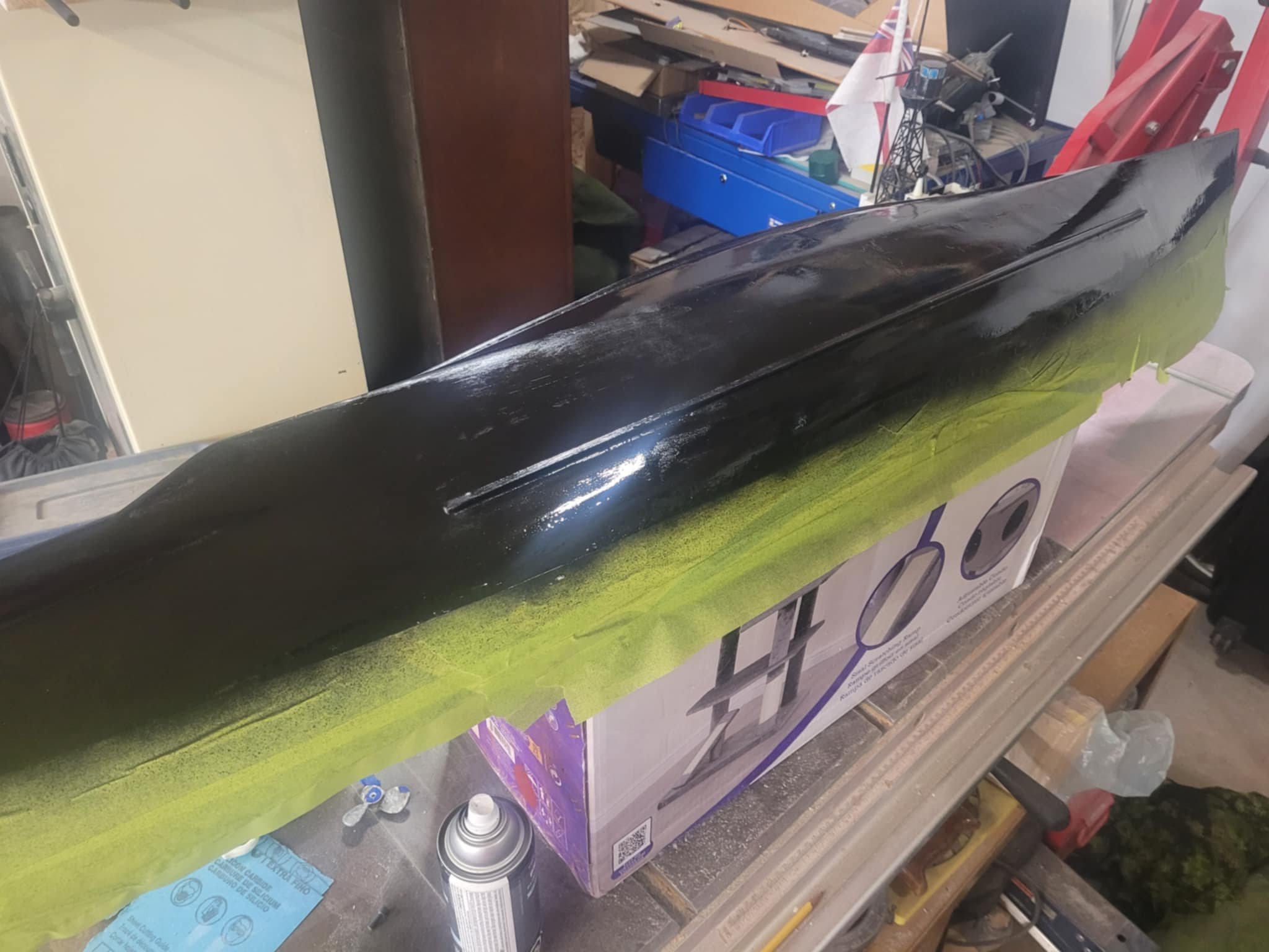
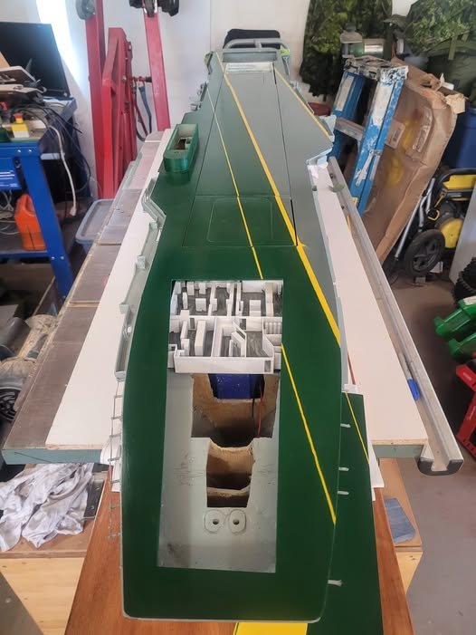
Hull is looking GREAT after the 2nd coat, so I've switched her to being upside-right, and we've got some minor repairs completed, a new coaming lip added, some internal supports to keep the deck from sagging, and a layer of epoxy on the uppers. I think she's nearly done.

-
Second layer of epoxy is added and is now curing. Once that's done, I'll be flipping her right side up again and will finish up the uppers - ready to shift here to her new home in Ontario in a couple of weeks! NS
-
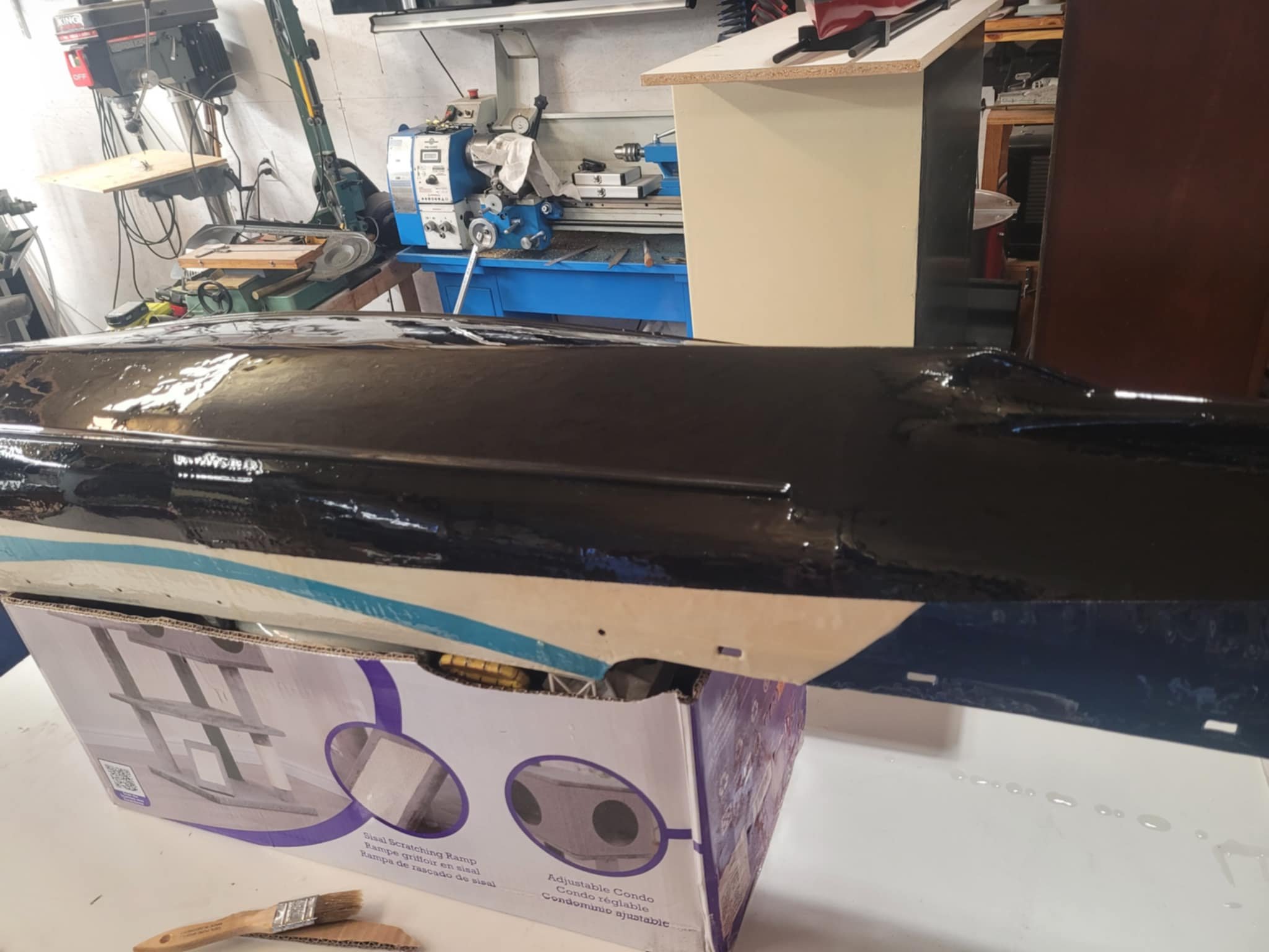
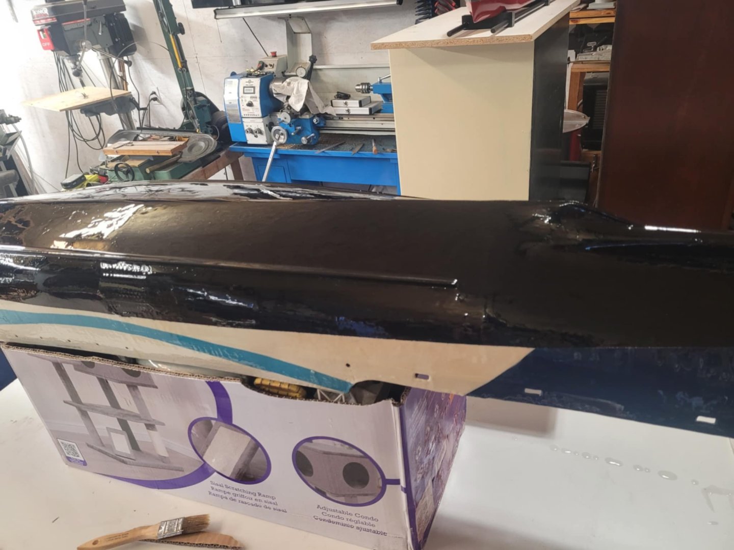
Fresh layer of West System Epoxy laid up on the hull tonight. We'll see if she needs a second coat.
-
Wait a sec...looking at that box art...the flight deck on that carrier is angled. That wasn't a thing until after WW2! Were they still using Tiger Moth aircraft for carrier deck landing practice in the 50's?
-
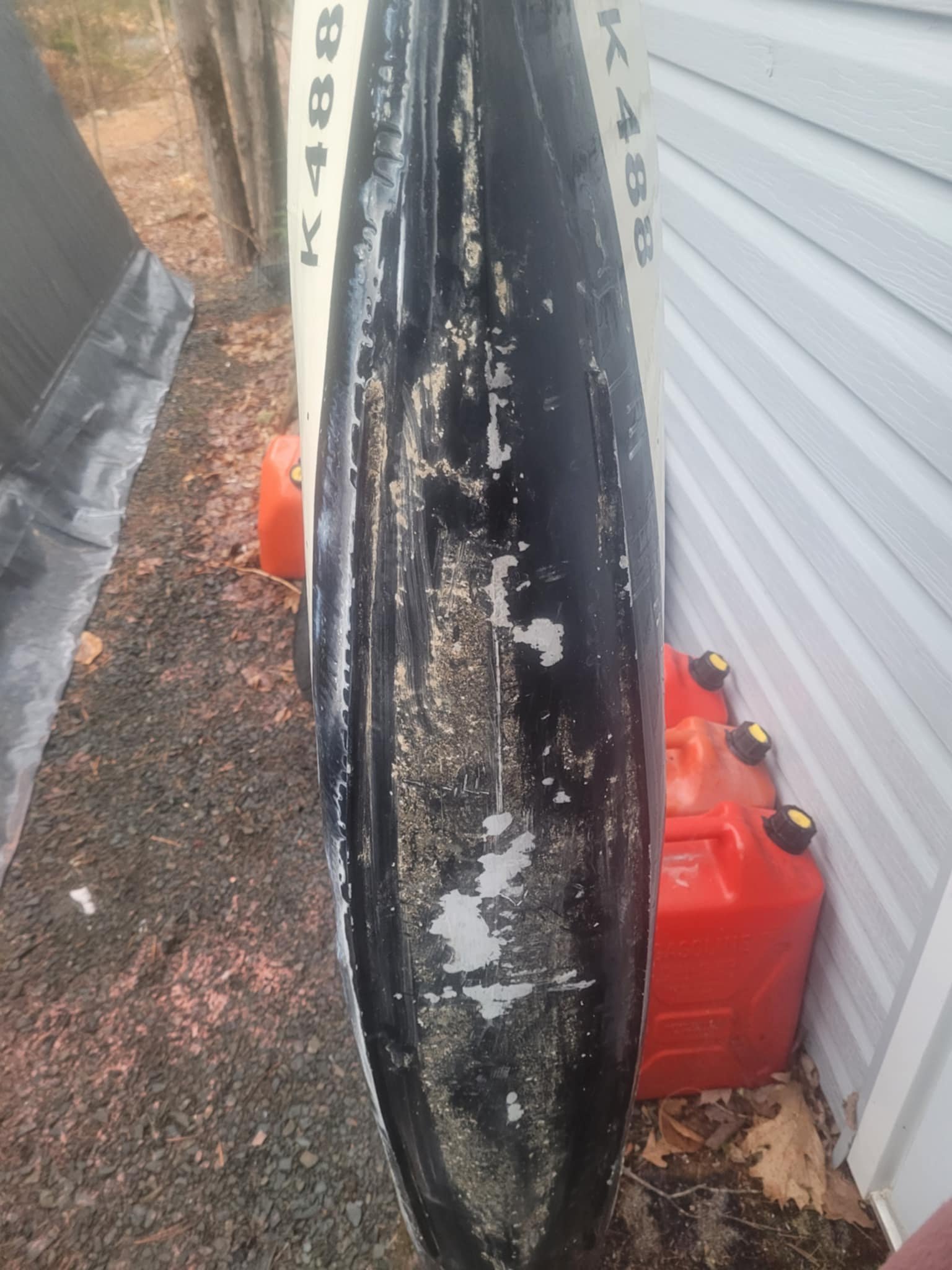
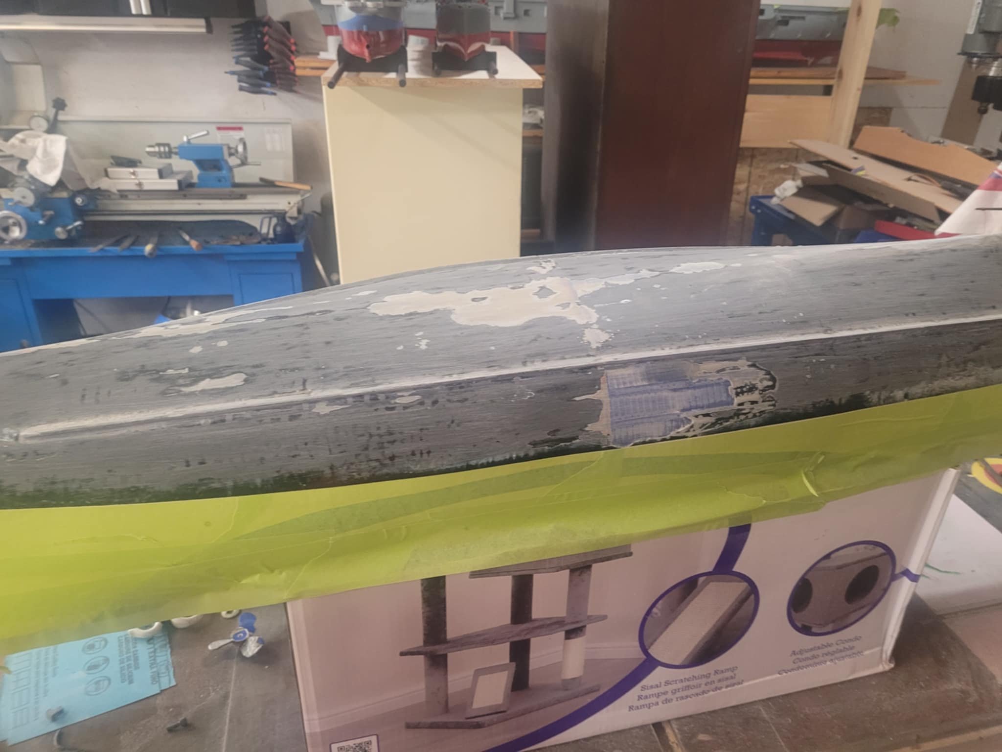
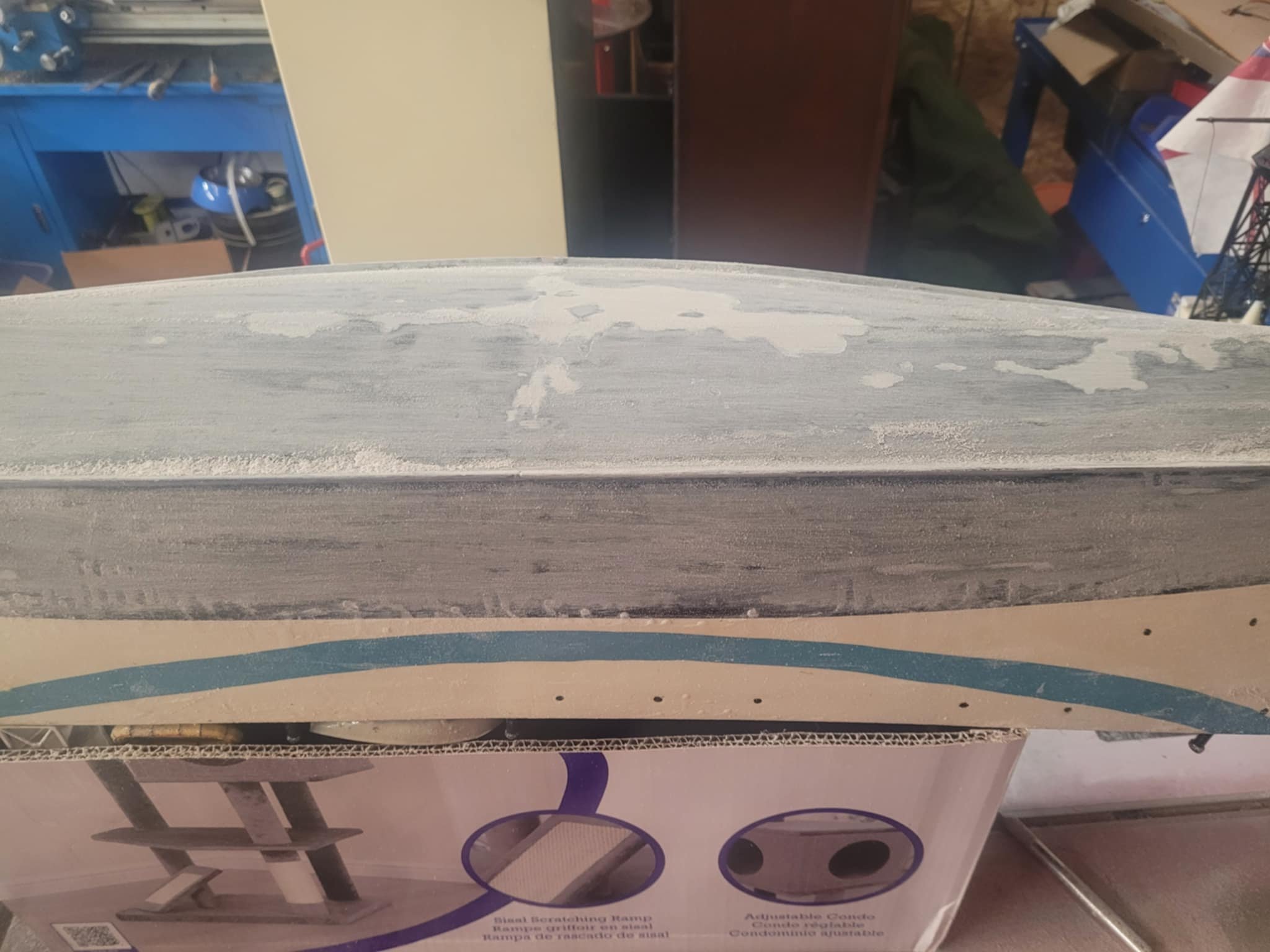
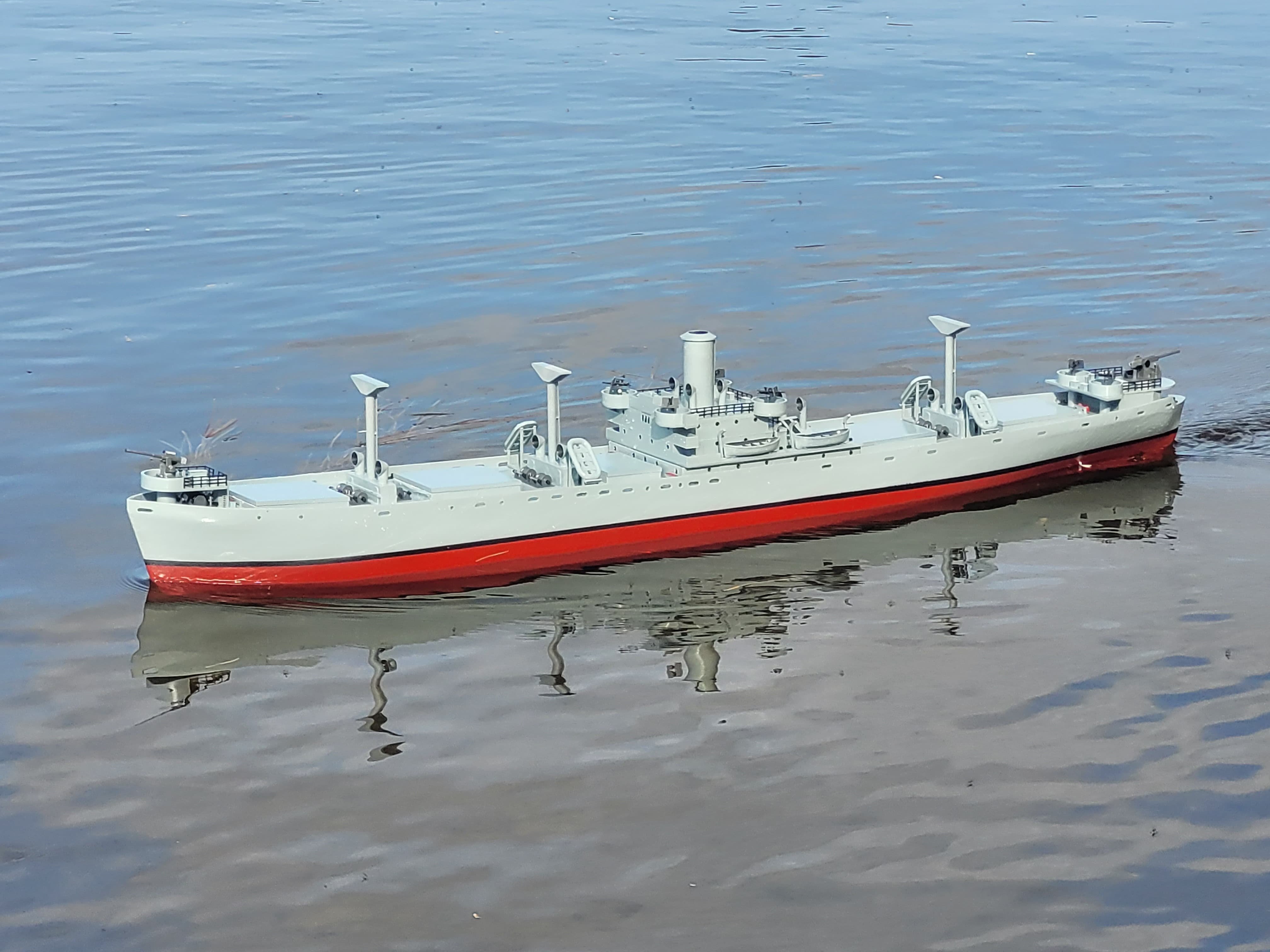
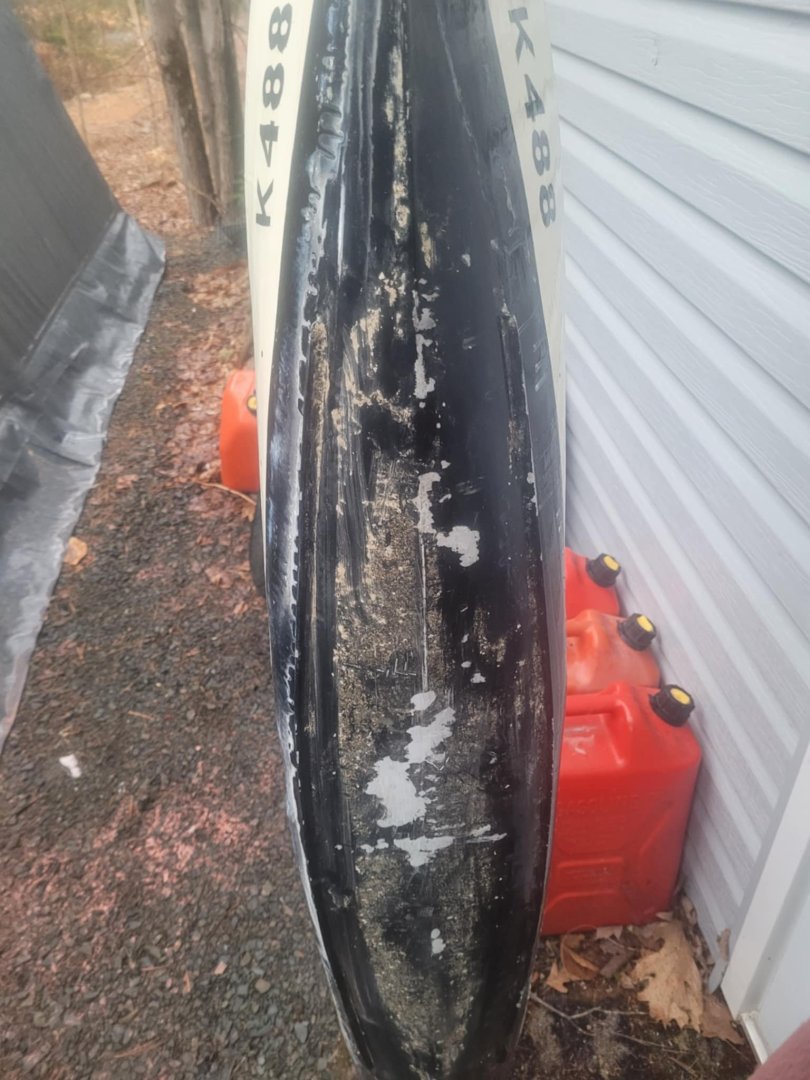
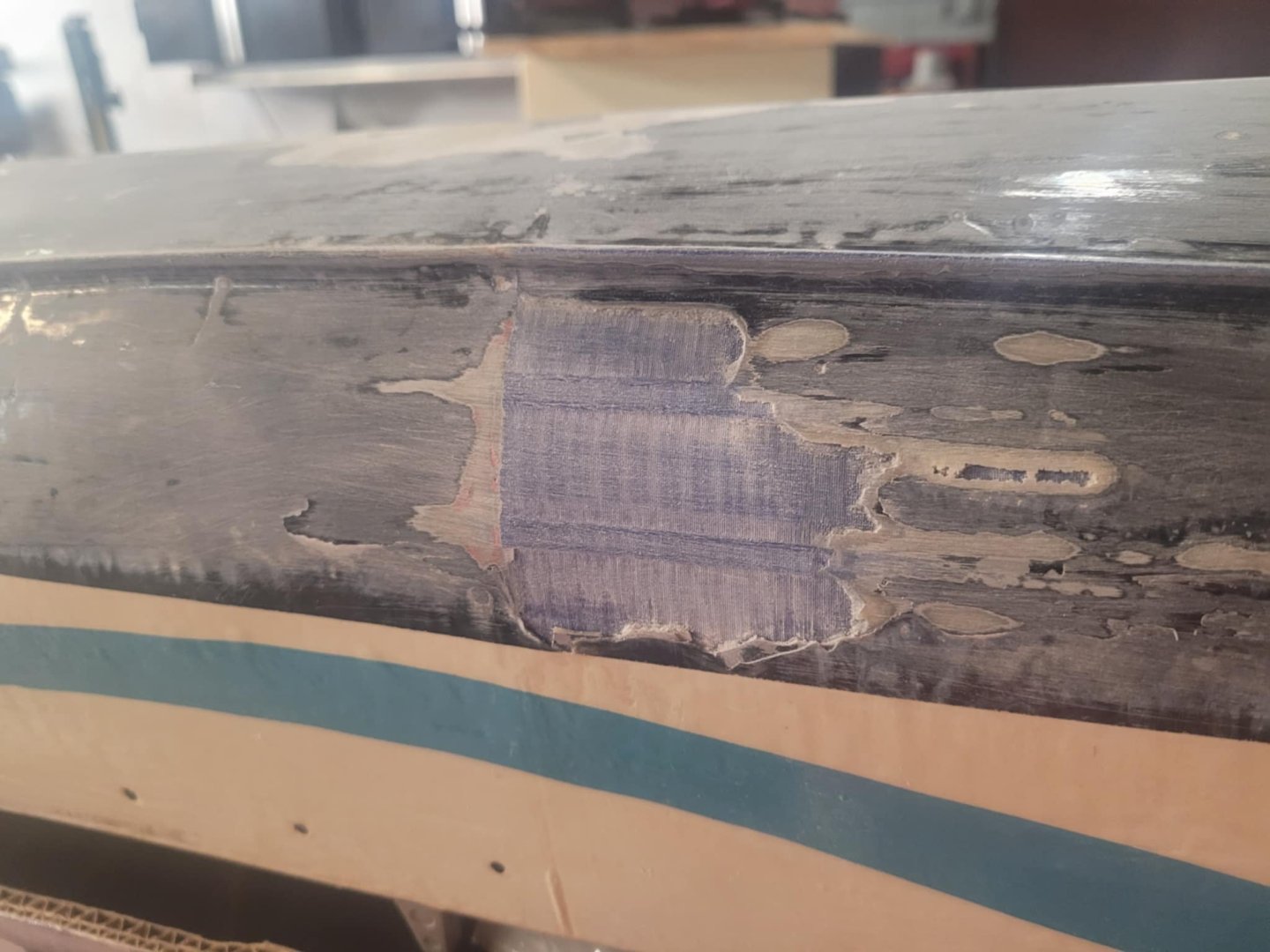
Well, spring is springing....so....time to get out the St Thomas and tidy her up. There may be a 02 May Deadline on repairs...so....she's shifted to the fore-front for repair work. I took her out and did some sanding, you can see the damage to the bottom of the hull that the duck poop in the duck pond did. She's now sanded clean, including the bulged area that bubbled off.


-
Solving the infrastructure problem before going to the details - good plan. Looks like a cozy old house - what part of the world are you in? Guessing Borden-ish if your partner is with 400 Tac Hel. I may be visiting out thataways in September-ish. Good luck with the Mossie!