NavyShooter
-
Posts
692 -
Joined
-
Last visited
Content Type
Profiles
Forums
Gallery
Events
Everything posted by NavyShooter
-
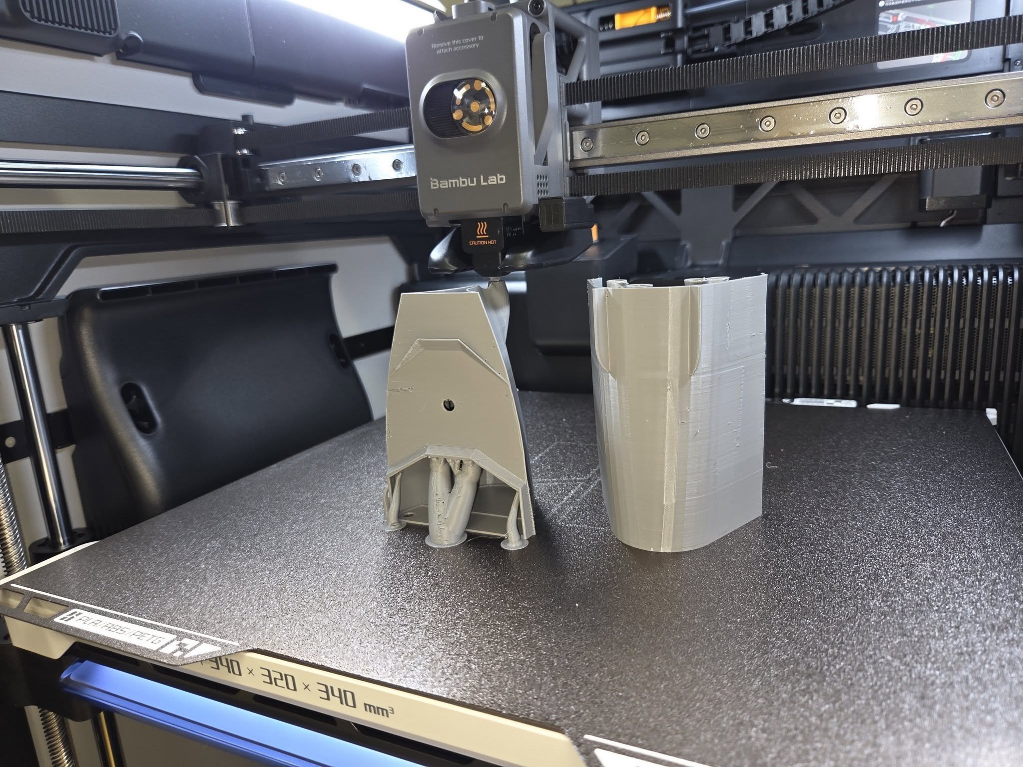
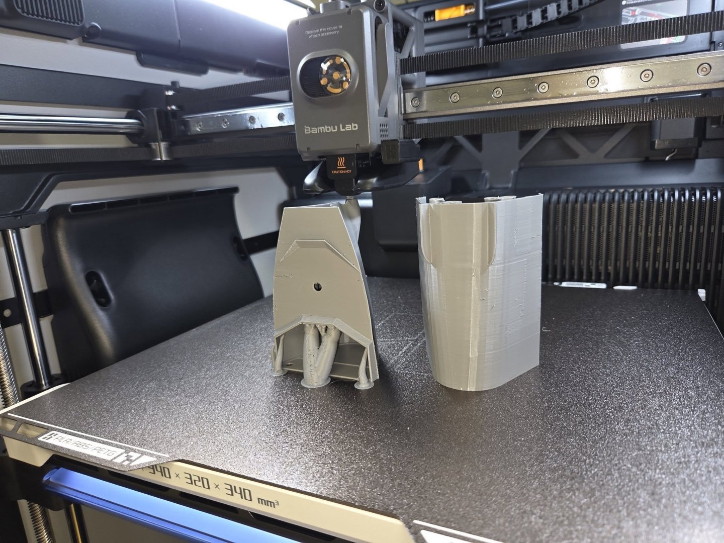
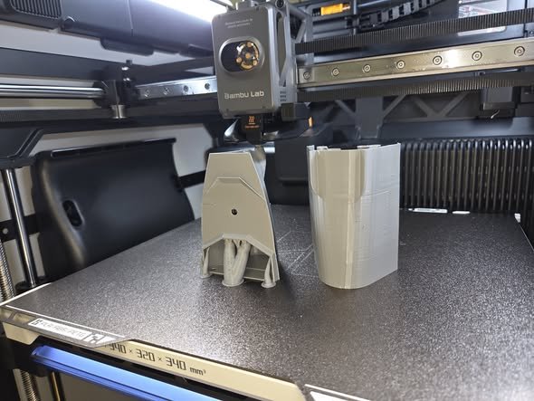
 Here's the test print. No major issues - going to go full steam ahead and print the 1:144 version over the weekend. It's a 2 day, 3 hour print (51 hours) for the entire hull.
-
Here's the forward half of the ship - printing at 'ludicrous' speed now. It'll be done in...17 minutes. Wow.
-
OK, New printer (Bambu H2S) is setup and running now. I've got a re-do of the hull for the R/C version printing at 1/288 scale as a test, and if that goes well, I'll click 'print' and on Monday I'll have a 1/144 sample hull waiting for me in 4 segments.
-
David, WRT the door - that door was a bit sticky in how it was assembled - I think I'm going to be making sure going forward that the doors are free moving and not sticky - see if that changes how they launch. My new Bambu Labs H2S has shown up, and is going through it's calibration right now. 🙂 Good. Also, I presented the V2 model last night to the RCN Command Chief for him to display in his office in Ottawa. His problem to get it back there 🙂 It was much appreciated, and he's going to send me a couple of photos of it once it's all setup and on display. He was super excited about having the first T26 model at NDHQ. I expect his office will get a few jealous visitors! NS
-
Phil, that's amazing brass work! Well done good sir! You have the 'heat shield' part of the grenade lockers right - having been an ammunition custodian on a modern warship (Halifax Class) all of our upper deck lockers had a heat shield which was normally painted white that was stood off a couple of inches from the lockers to provide shade and natural cooling. Originally, as fitted, the ships didn't have these heat shields, and we ended up having to put shot matts on top of some of the lockers and put a fire-hose spraying a light amount of water over them to provide some cooling while in the Persian Gulf back in the 2001 time-frame.
- 484 replies
-
- 4
-

-
- minesweeper
- Cape
- (and 1 more)
-
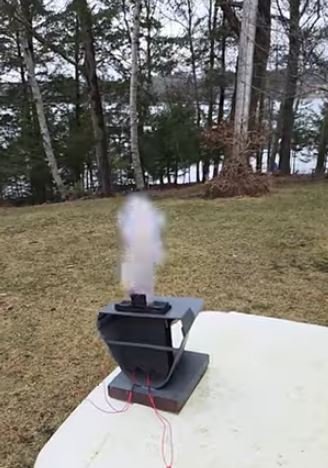
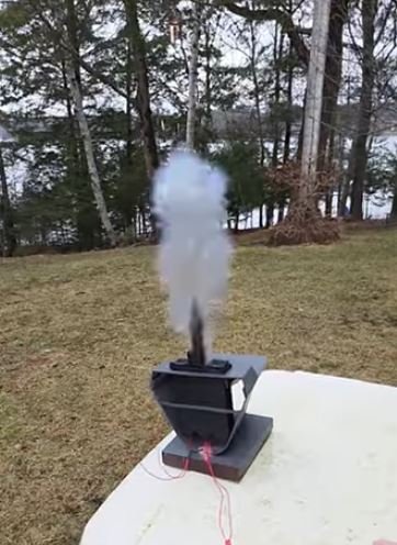
The two test shots went between 30-80 feet I think. The one fired with the cover/door open already flew straighter than the one which had the door closed. I'm pondering the results.
- 54 replies
-
- 1
-
-
- Type 26
- City Class
- (and 2 more)
-
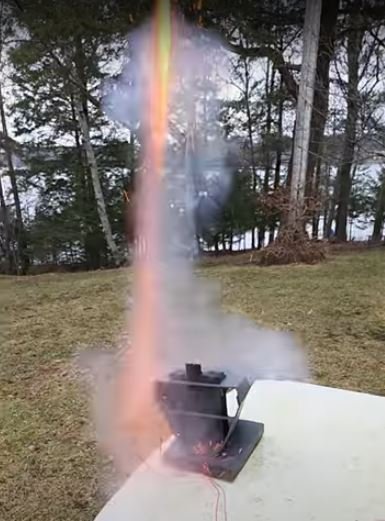
Today was the test launch day for V4 of the VLS system. Worked ok. I sealed the entry point for the ignitor into the launch tube with hot glue, and it looks like one of them didn't seal quite perfectly, that's OK...it's a learning curve. The second was better sealed. The brass plates I glued into the J-tube at the bottom got blasted apart - viewed with a flashlight, it's clearly destroyed. The one without the brass survived the shot OK as well - so - I think I'm going to go without the brass and make them expendable after a single shot instead of worrying about the brass if it's going to get destroyed anyhow. The missiles - first shot went straight up about 60-80 feet or so and the parachute ejection charge went "pop" quite nicely up in the air. Shredded the 'missile' - I considered it expendable anyhow, so no big deal. I had the launch door open for the first shot, so it went straighter. The second shot I left the launch door closed, and it opened just fine when fired - but I think that deflected the shot and so it went across instead of up - ended up about 30 feet away, 30 feet up in a tree when it popped the parachute ejection charge. Overall - I am pleased.
- 54 replies
-
- 3
-
-
- Type 26
- City Class
- (and 2 more)
-
I have no formal confirmation as to exactly where things go, so this is my 'best guess' based on some informal chats with some friends. I'm open to being incorrect....in fact, I know there's parts of this model that are wrong, but that's OK since the ships themselves don't even exist yet. Nice thing about it being a 3D design is that I can adjust on the fly, and V3 will be closer than V2....and V4 will be even closer still.
- 54 replies
-
- 1
-
-
- Type 26
- City Class
- (and 2 more)
-
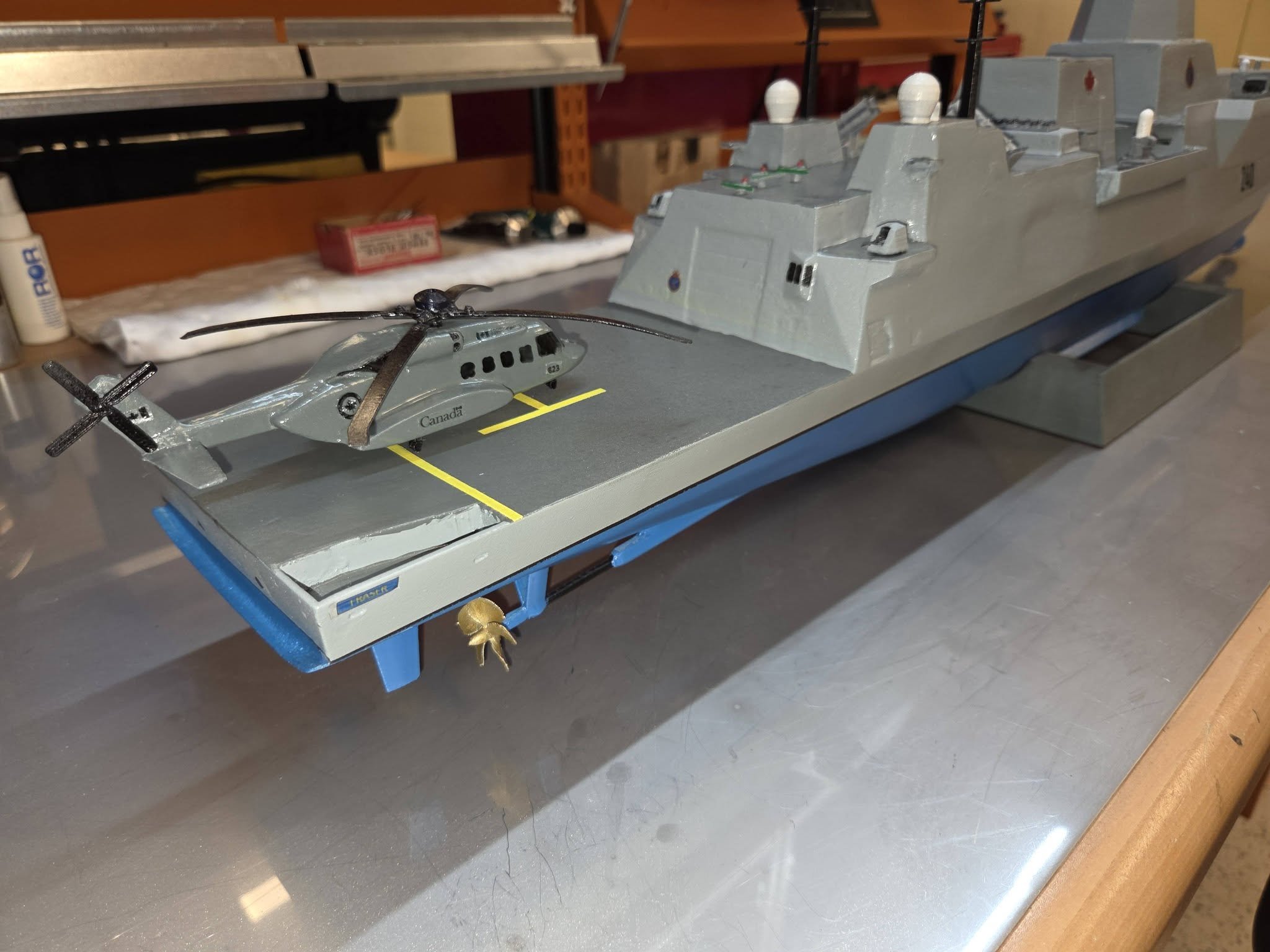
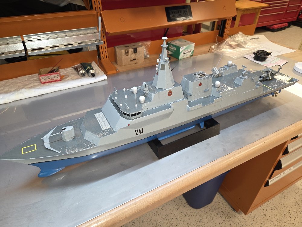
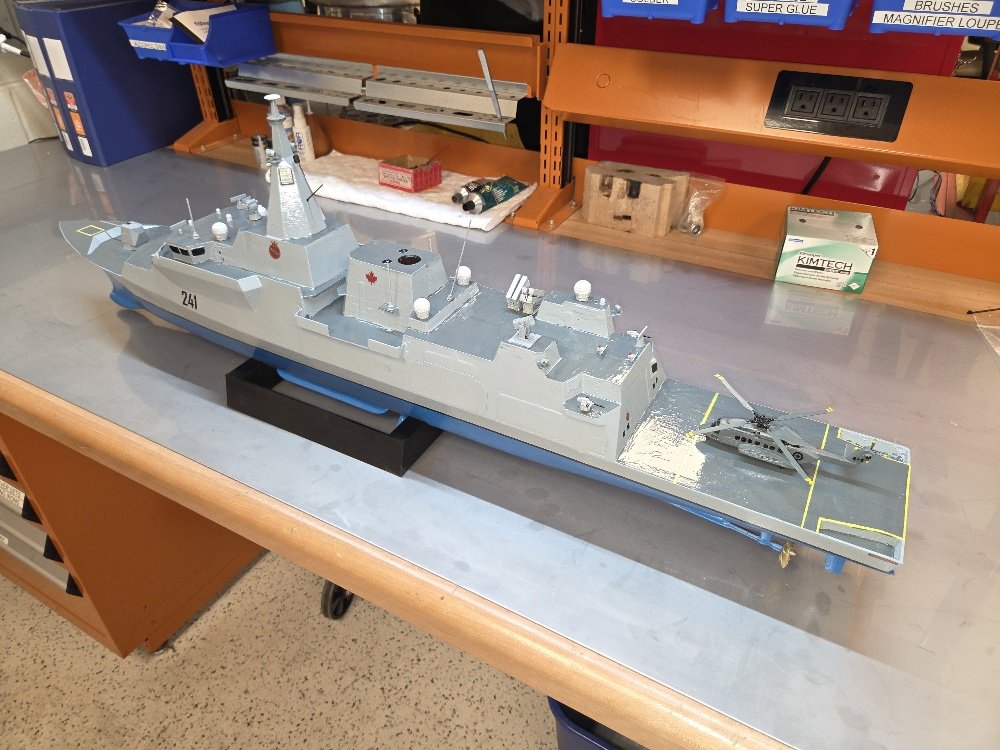
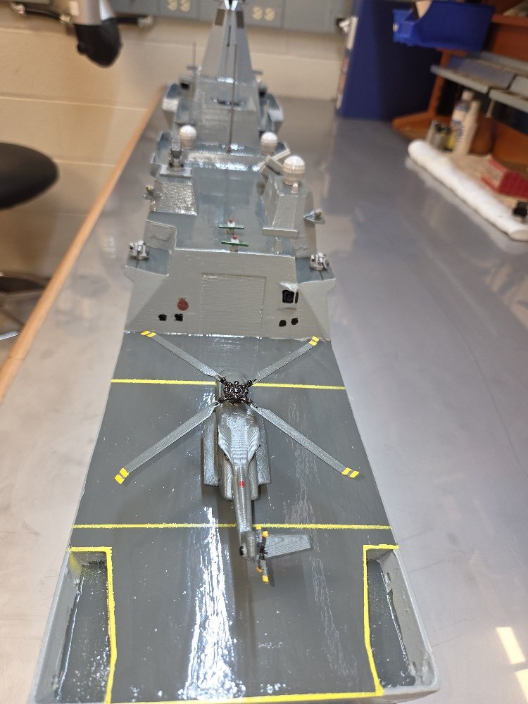
Hoisted a flag (ok, it's glued in place...whatever....) and am calling V2 complete. Here we have DDH 241 - HMCS MacKenzie The next one will be the first of the R/C version(s?) - we'll see how it goes. I'm quite pleased with how this is looking. I understand that this is closer to the 'actual' look, but not quite correct - V3 has further revisions to the superstructure to match the RCN version more closely.


- 54 replies
-
- 6
-
-
- Type 26
- City Class
- (and 2 more)
-
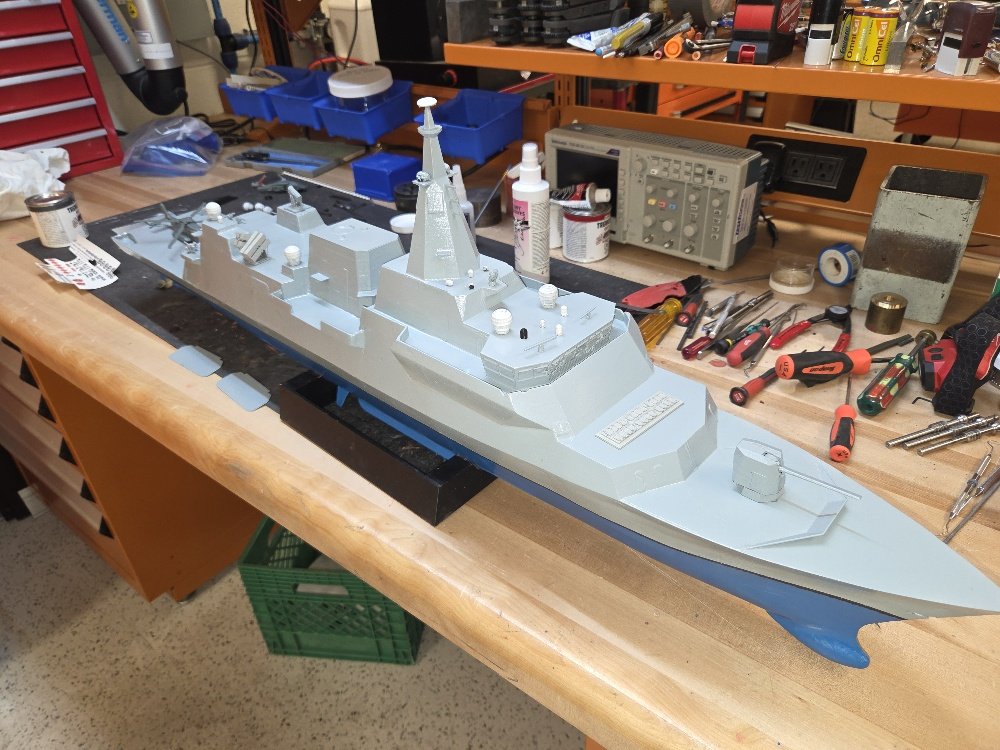
V2 is ready for decals, and some of the 'detail bits' have been glued on.

- 54 replies
-
- 3
-
-
- Type 26
- City Class
- (and 2 more)
-
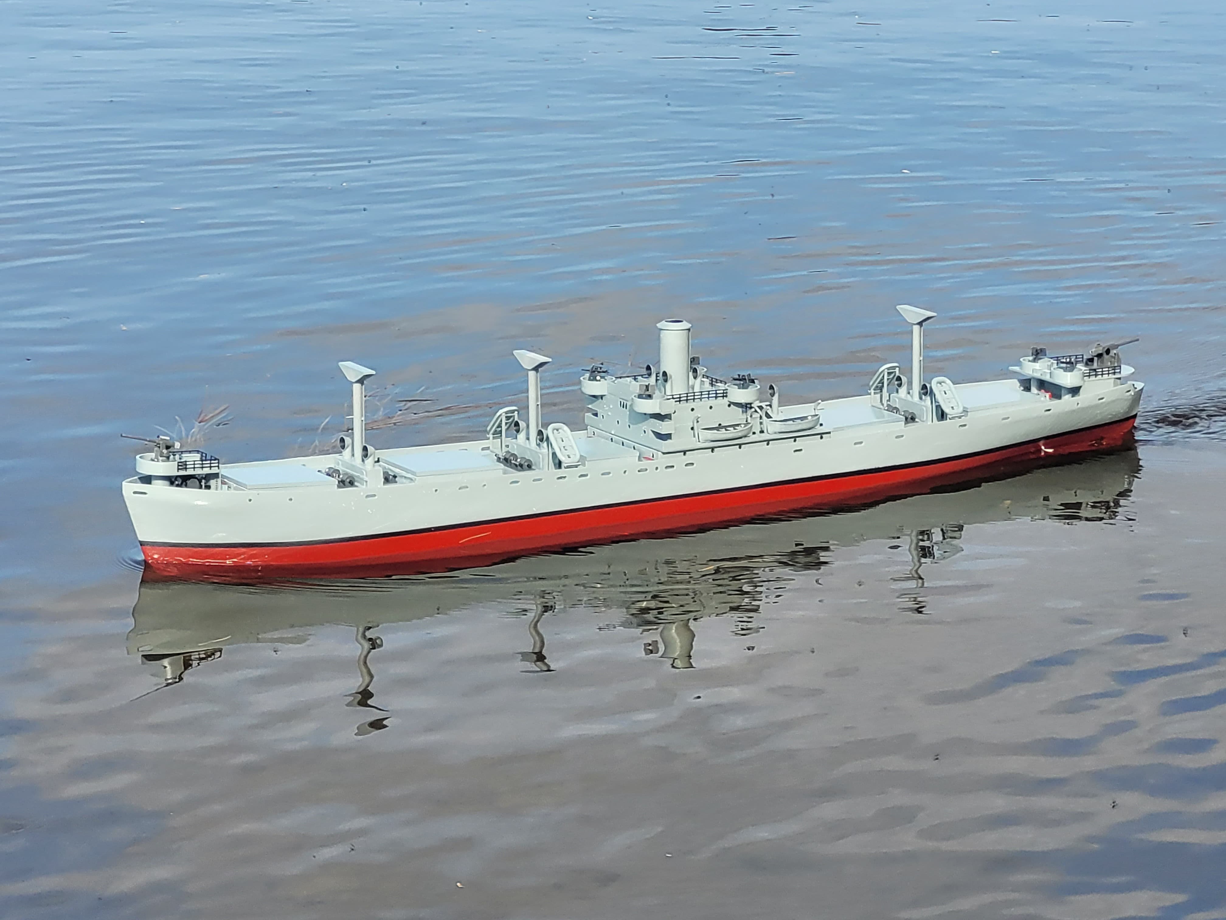
Observation - the below the waterline colour on the ship should be BLACK not red. That was some feedback I got from the crew of HMCS Sackville as I was working on my model of her (and the St Thomas model I did as well.) NS
-
OK, HMCS St Thomas will likely be moving to Ontario this summer (at last) and I've got a model of HMCS Sackville that's spent the summer in the pond. Here's the touch-up paint on the hull of Sackville that I applied today. I'll do the port side tomorrow.


-
OK, so, paint is applied, I need to paint the decks (tomorrow) and then we can start glue action to put some of the little bits on!
- 54 replies
-
- 5
-
-
- Type 26
- City Class
- (and 2 more)
-
Ian, I will suggest that BOTH platforms would have a Nav Radar. A longer one with longer pulse-length that will perform better in the rain, and a shorter one that's more precise, but susceptible to weather impact. Also, being a ship conducting passenger travel, it may be required by IMO regulations to have 2x Nav Radar sets. As for lights - you should have a white masthead steaming light. Brad
- 24 replies
-
- 3
-

-
-
- ferry
- Europic Ferry
- (and 1 more)
-
Looks like a neat build! Are you planning on having the ramp functional?
- 24 replies
-
- 1
-
-
- ferry
- Europic Ferry
- (and 1 more)
-
Anddd.....bumped into a buddy over the weekend who's working on the project, and it turns out I had the right version of the RAM launcher initially.... The 11 shot SeaRAM launcher is (I think - based on my assumptions) designed for ships that need a stand-alone AA missile system. The 21 shot launcher is designed for ships that have an integrated Combat Management system and don't need a launcher with it's own integral detection/engagement Radar system. So. Back to the 21 shot launcher I guess.
- 54 replies
-
- 1
-
-
- Type 26
- City Class
- (and 2 more)
-
The CIWS I had on V1 was the 20mm Phalanx...and that's not the right version. Turns out the 'correct' version (for now, conceptually) is the 11 shot SeaRAM launcher with the radome. So....here we go. Some more 3D design work.


- 54 replies
-
- 5
-
-
- Type 26
- City Class
- (and 2 more)
-
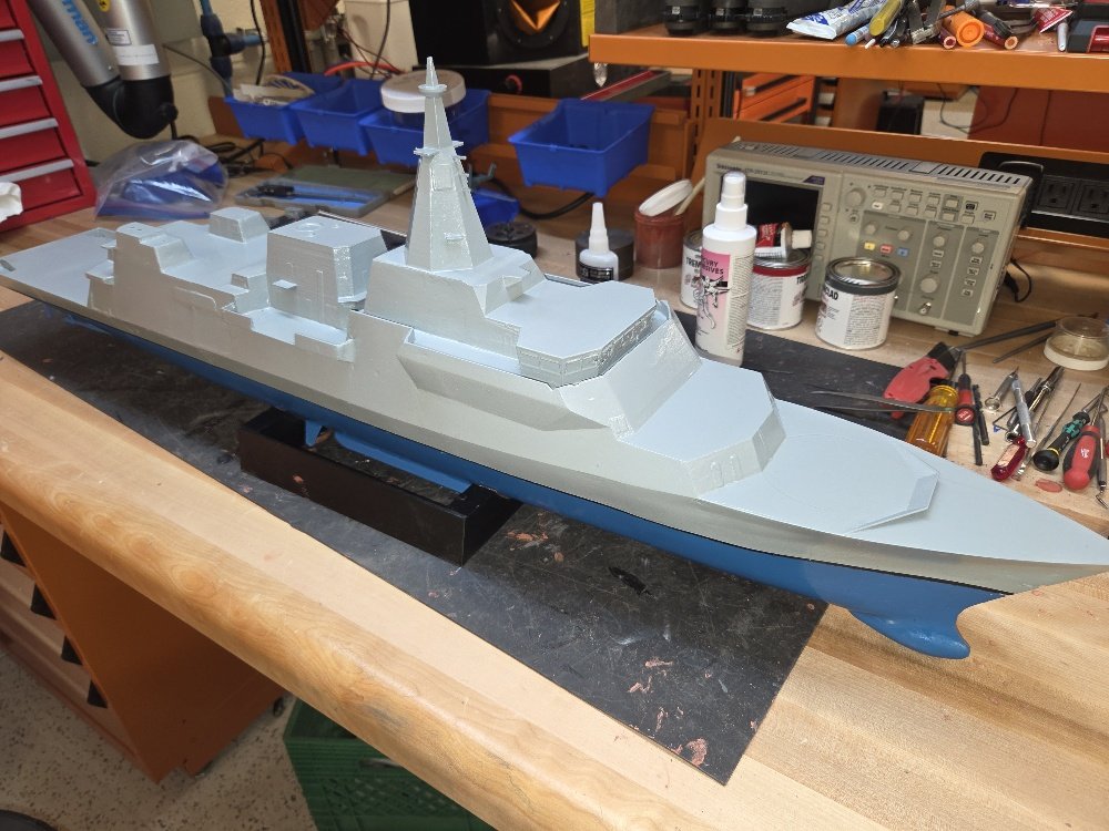
Hull #2 got a layer of blue today...then some minor putty addition, some sanding, and a final layer of blue to set over the weekend. Next week will see me getting the ship's side Gray done on the uppers, painting the 'non-skid' parts, then detailing. This one's probably going to be done by the end of next week. NS


- 54 replies
-
- 4
-
-
- Type 26
- City Class
- (and 2 more)
-
Today she got another shot of putty which dried quickly and got sanded, finished the sanding with some 180 grit - good enough for this one. At end of today, she's gray primed, and almost ready for some blue on the hull. I need to print and add the prop shafts in the morning then I'll be able to paint.


- 54 replies
-
- 4
-
-
- Type 26
- City Class
- (and 2 more)
-
I gave her a shot of primer yesterday before I headed home and she looked - OK.


- 54 replies
-
- 4
-
-
- Type 26
- City Class
- (and 2 more)
-
Well, hull #1 was presented to my unit's CO yesterday - she was quite pleased with the Fraser. Moving along with V2, she got a dose of putty, then some sanding yesterday morning.


- 54 replies
-
- 3
-
-
- Type 26
- City Class
- (and 2 more)
-
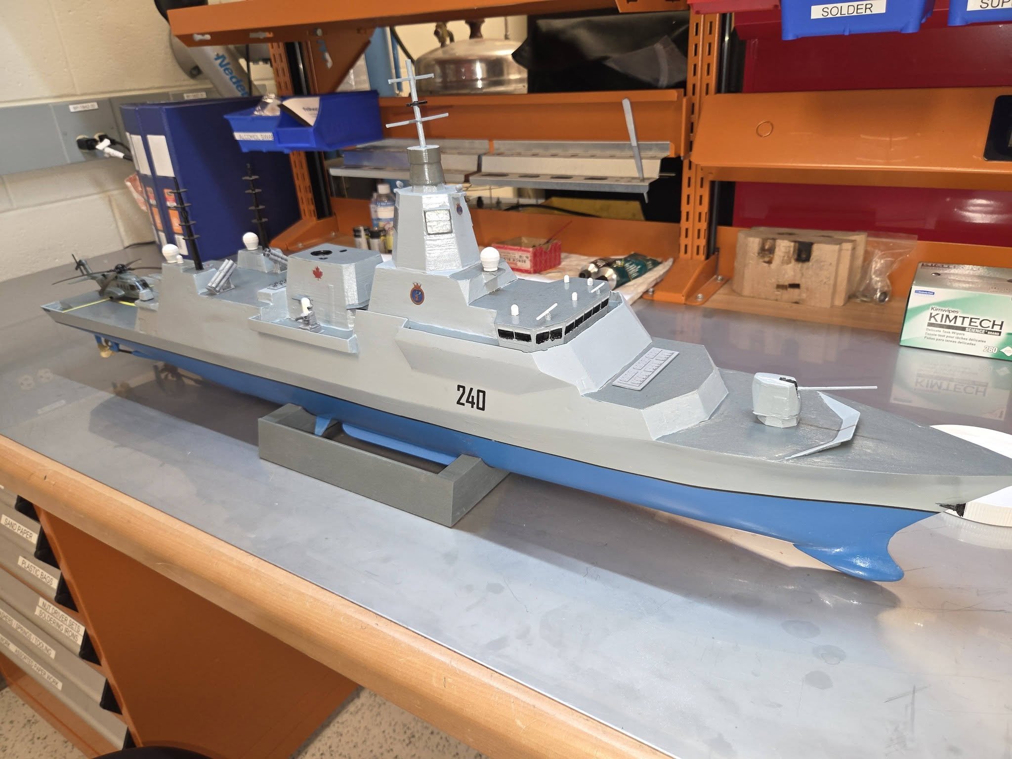
And here we are, HMCS Fraser DDH 240 is complete. Decals are applied and clear-coated. I'm generally pleased with how she looks - hull #2 will be better - second coat of putty was just applied. Hull #2 will also have a more accurate weapons loadout - I've made a model of both the SEA RAM launcher and the NSM, so CIWS and Harpoon will disappear on the next version.


- 54 replies
-
- 6
-
-
- Type 26
- City Class
- (and 2 more)