


Srenner
-
Posts
161 -
Joined
-
Last visited
Content Type
Profiles
Forums
Gallery
Events
Posts posted by Srenner
-
-
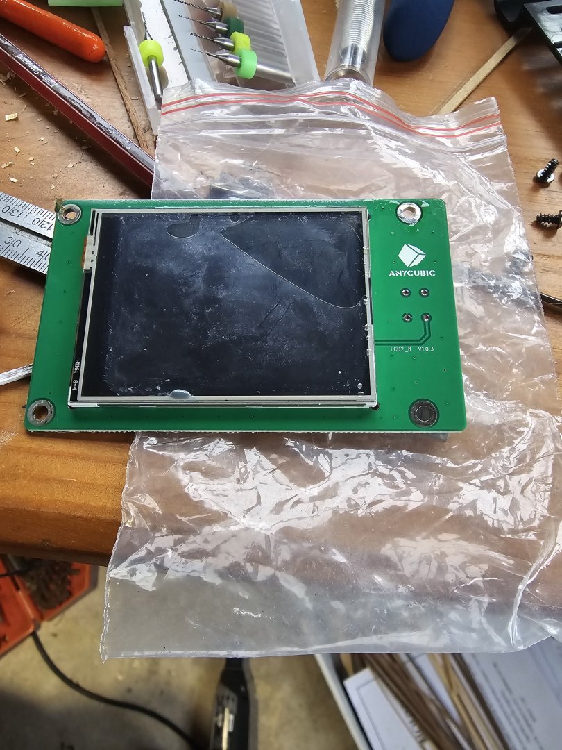
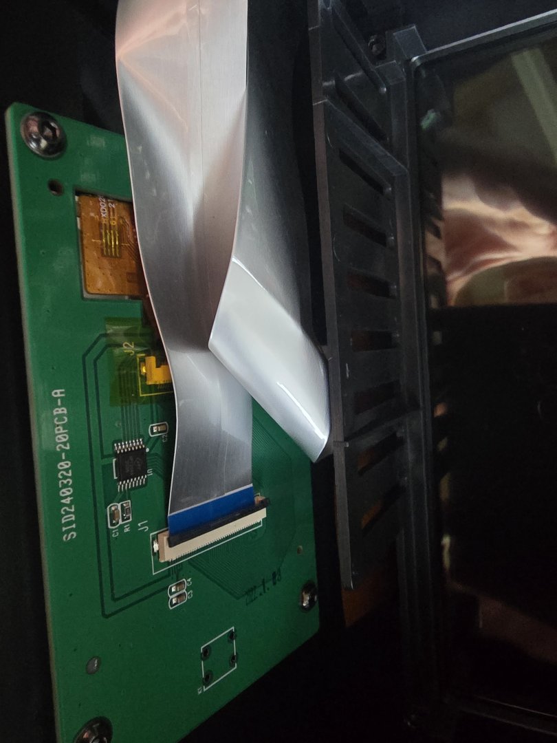
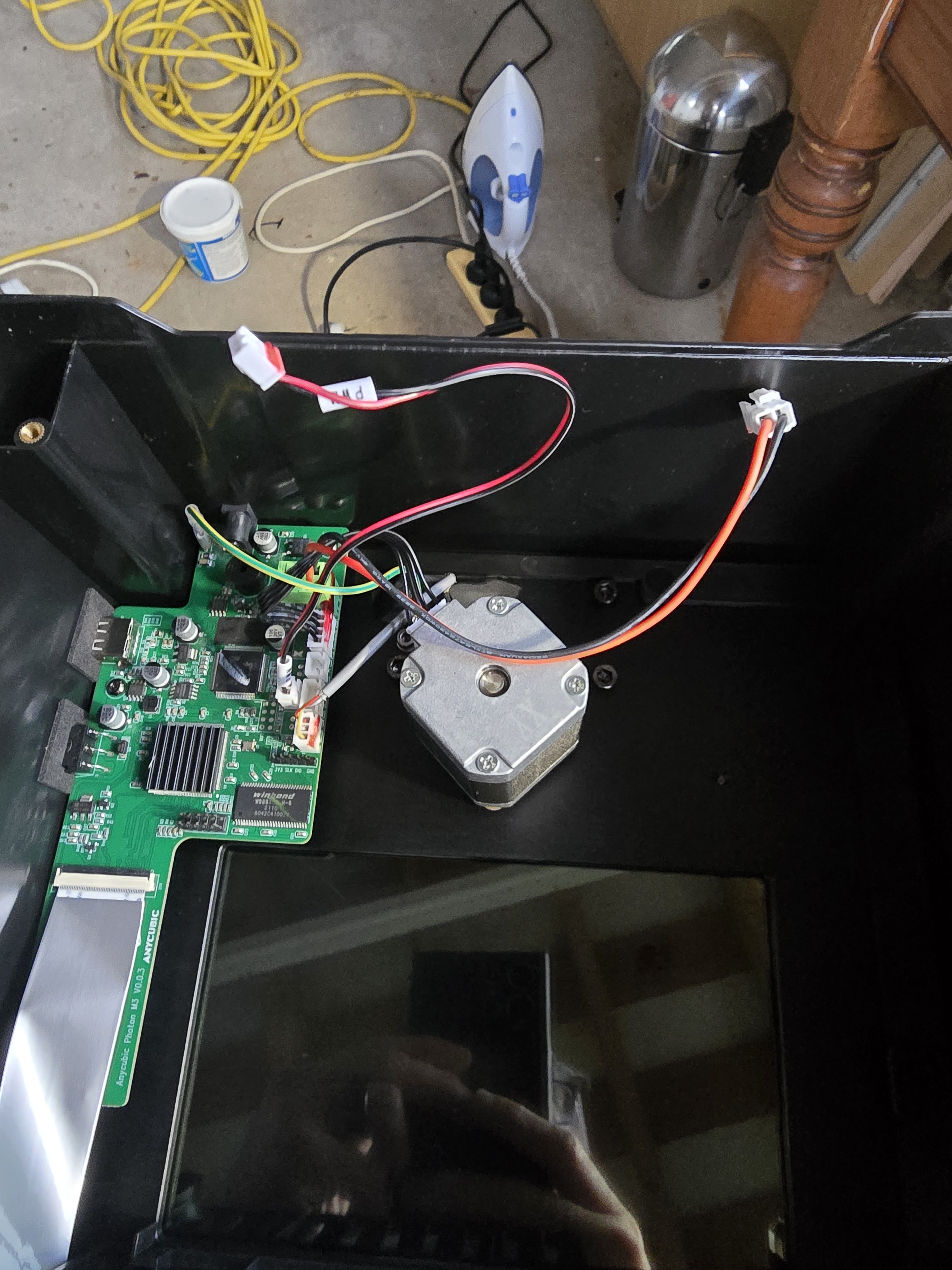
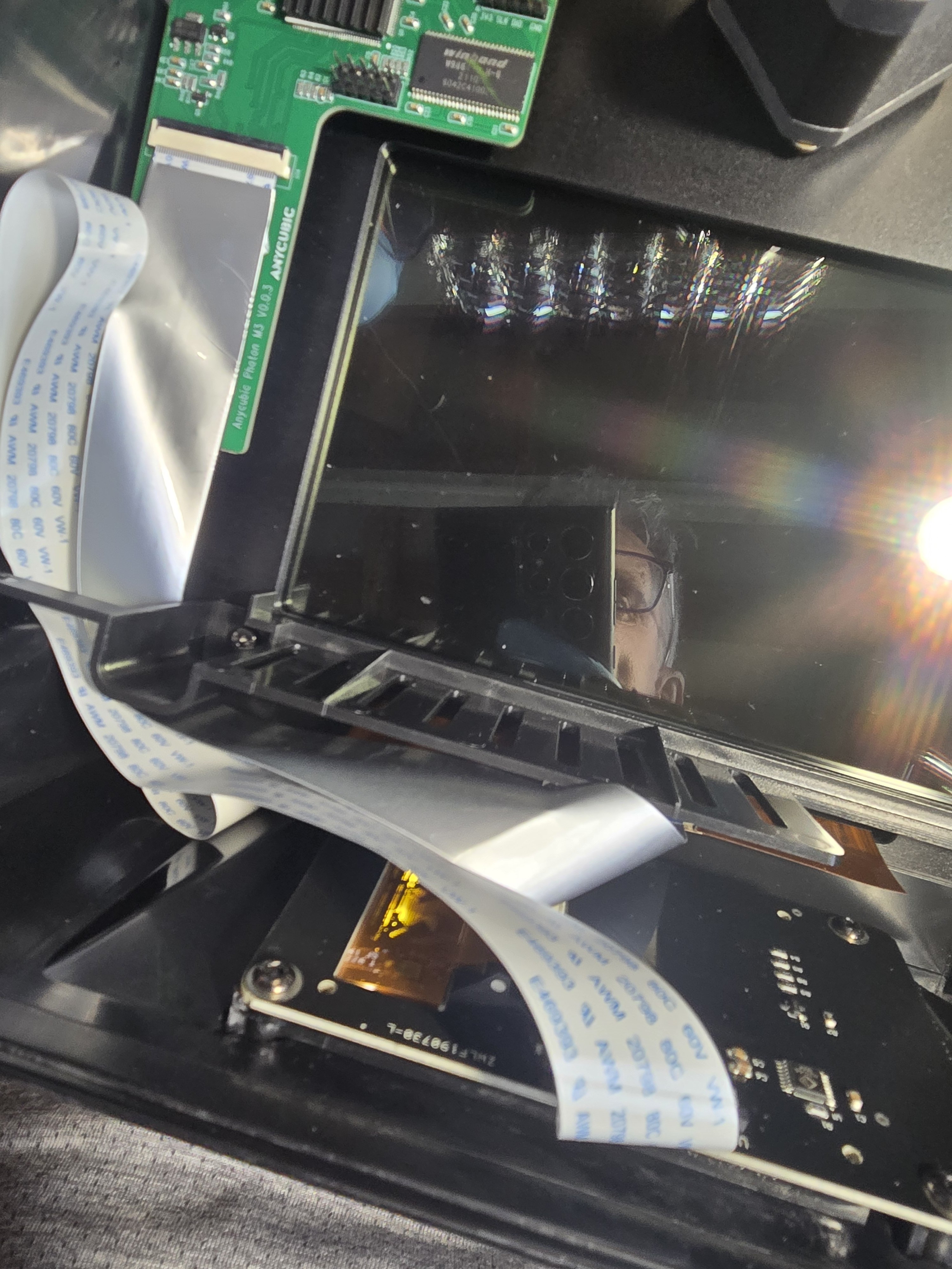
I have a anycubic photon m3 and the touch screen control panel cracked meaning it was really hard to use. So after googling around the process of changing spare parts didn't seem that hard, so I jumped in and tried to find a 2.8 inch touch screen replacement. Anycubic were out of stock so needed to find after market solution.
I can recommend that chitu systems who write chitubox have spares for printers and I ordered the 2.8 inch screen and 7 days later it arrived from China. No instructions but tonnes of videos on the web to sort of follow.
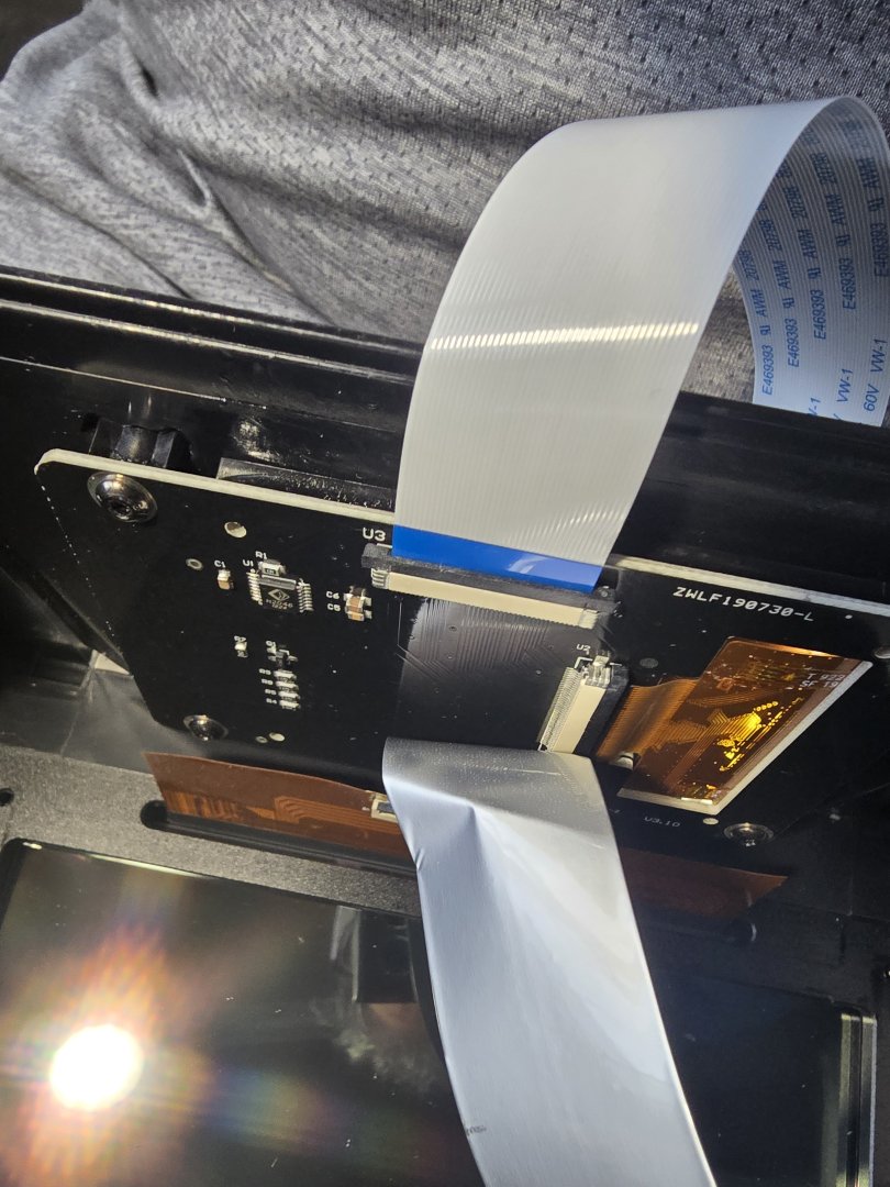
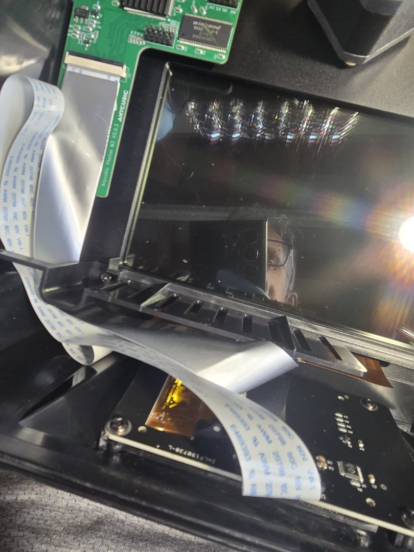
So the process to fix the screen is as follows, the photos document the steps as well:
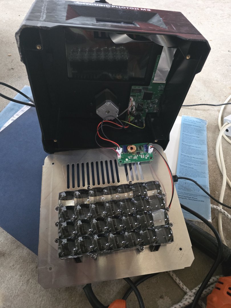
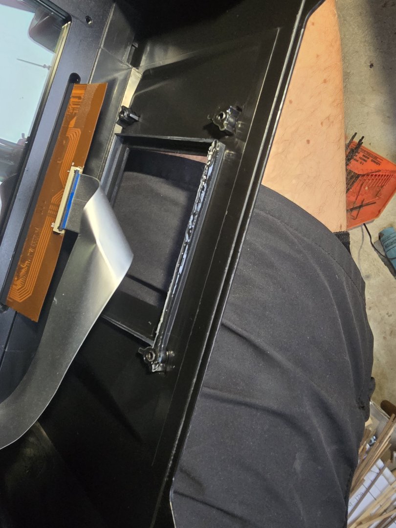
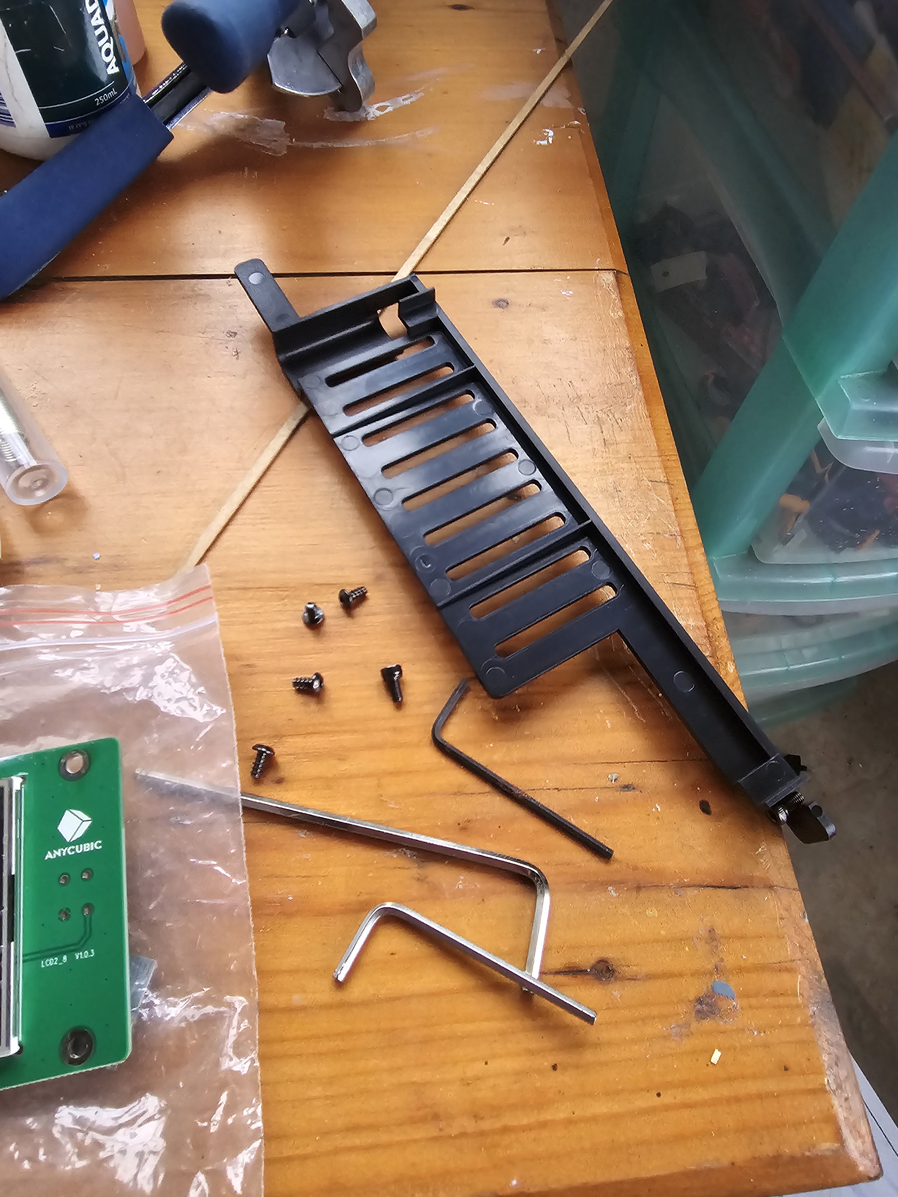
1. Take off the bottom plate screws and remove the bottom plate.
2. Undo the electrical cables to give better access
3. Take off the plastic guard to stop cables crossing into the lcd and laser area of the printer.
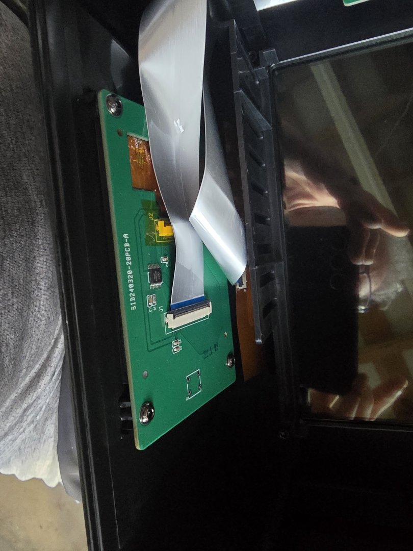
4. Take off the control panel card
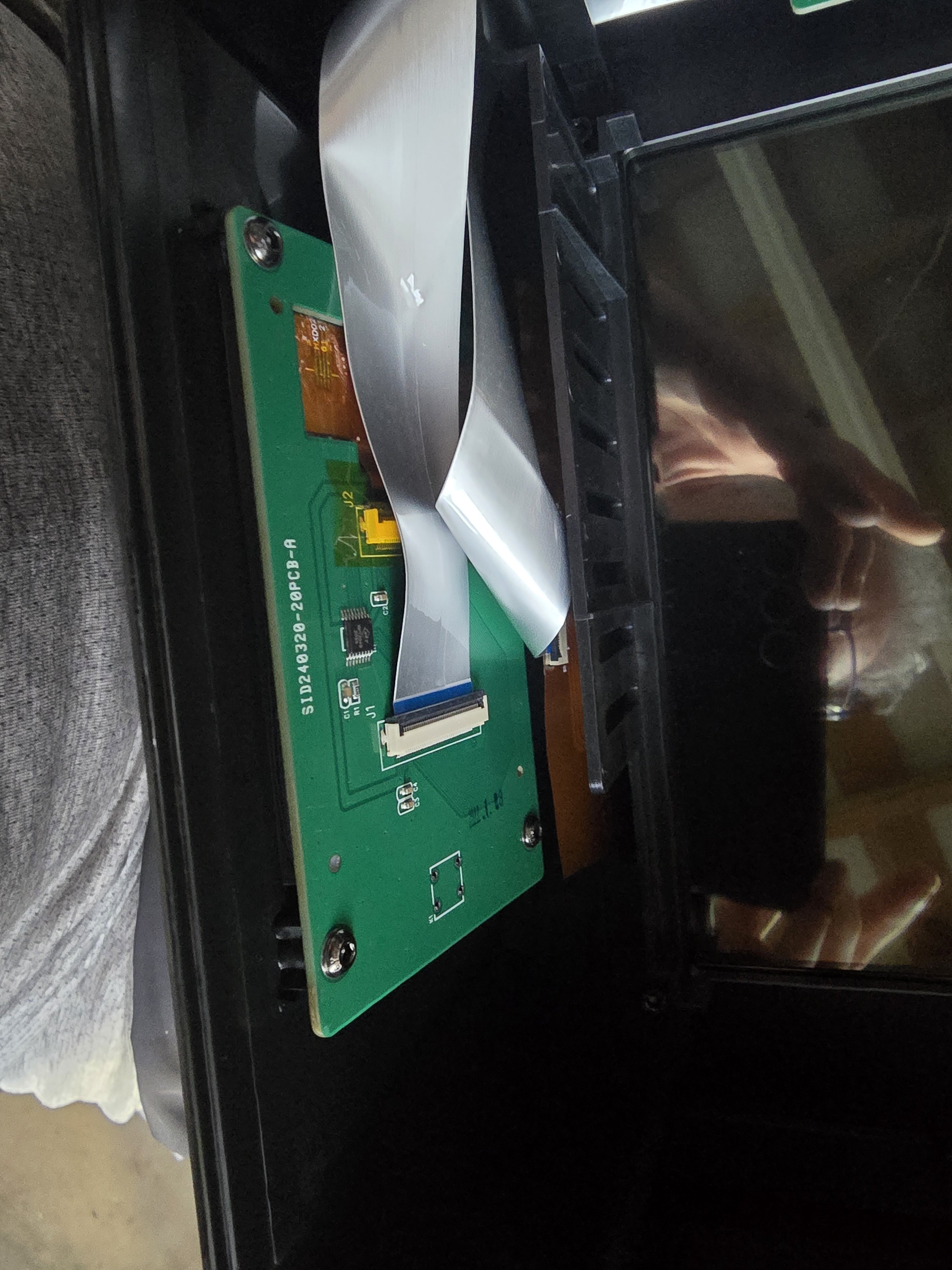
5. Undo the cables by flicking the little black bars on the connectors upwards.
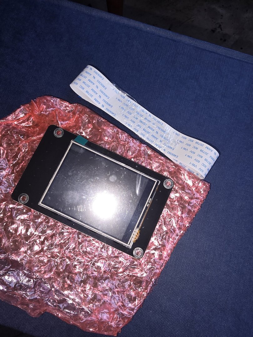
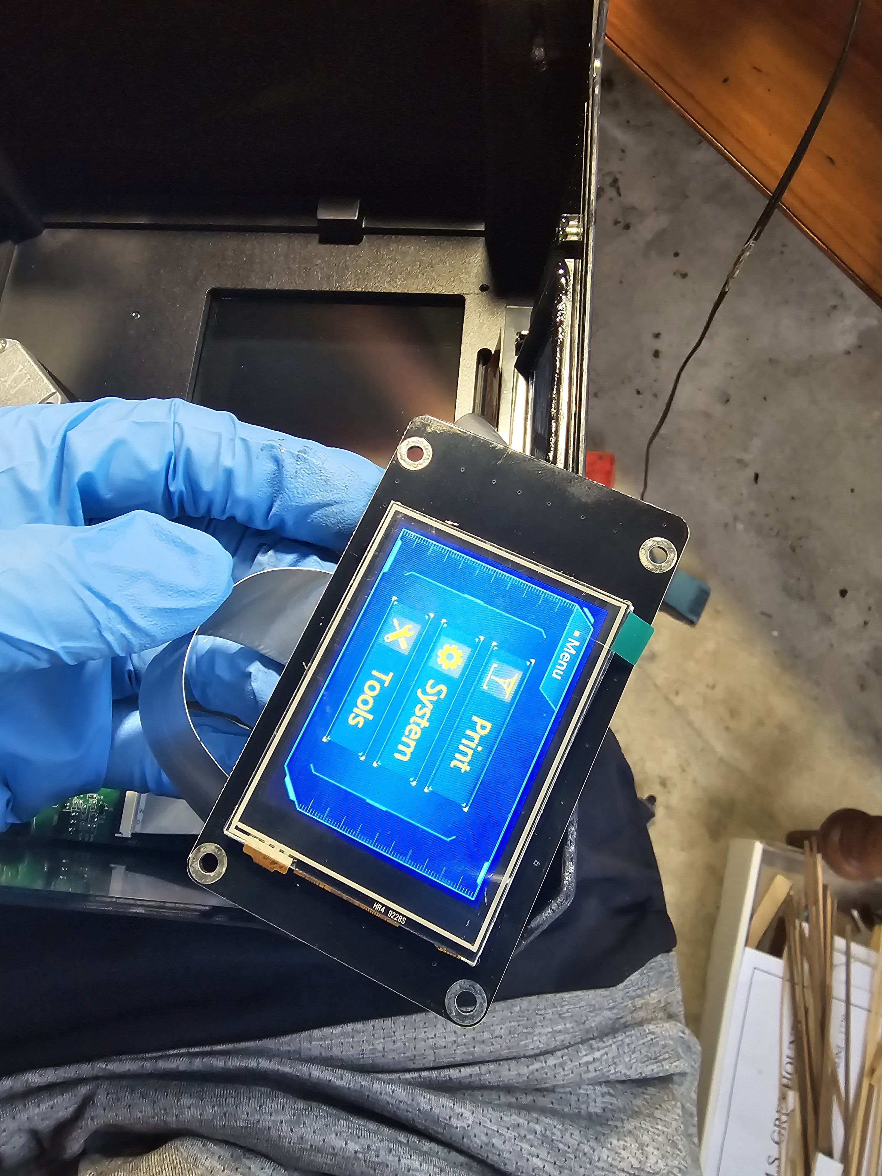
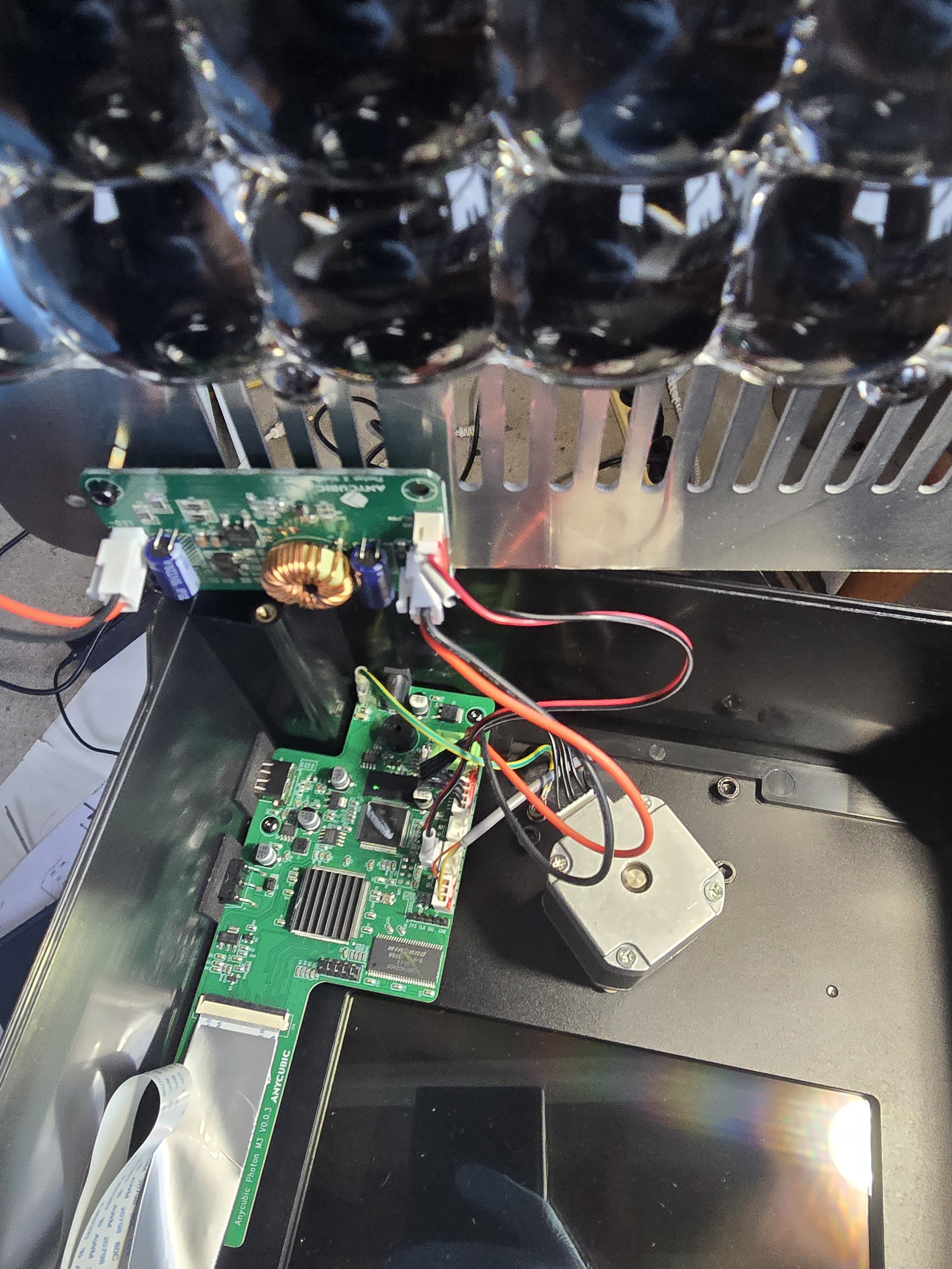
6. Plug in the new screen and make sure the screen going in the right way up. There are no marks indicating the top on the Chinese card.
7. Re screw the screen into the printer.
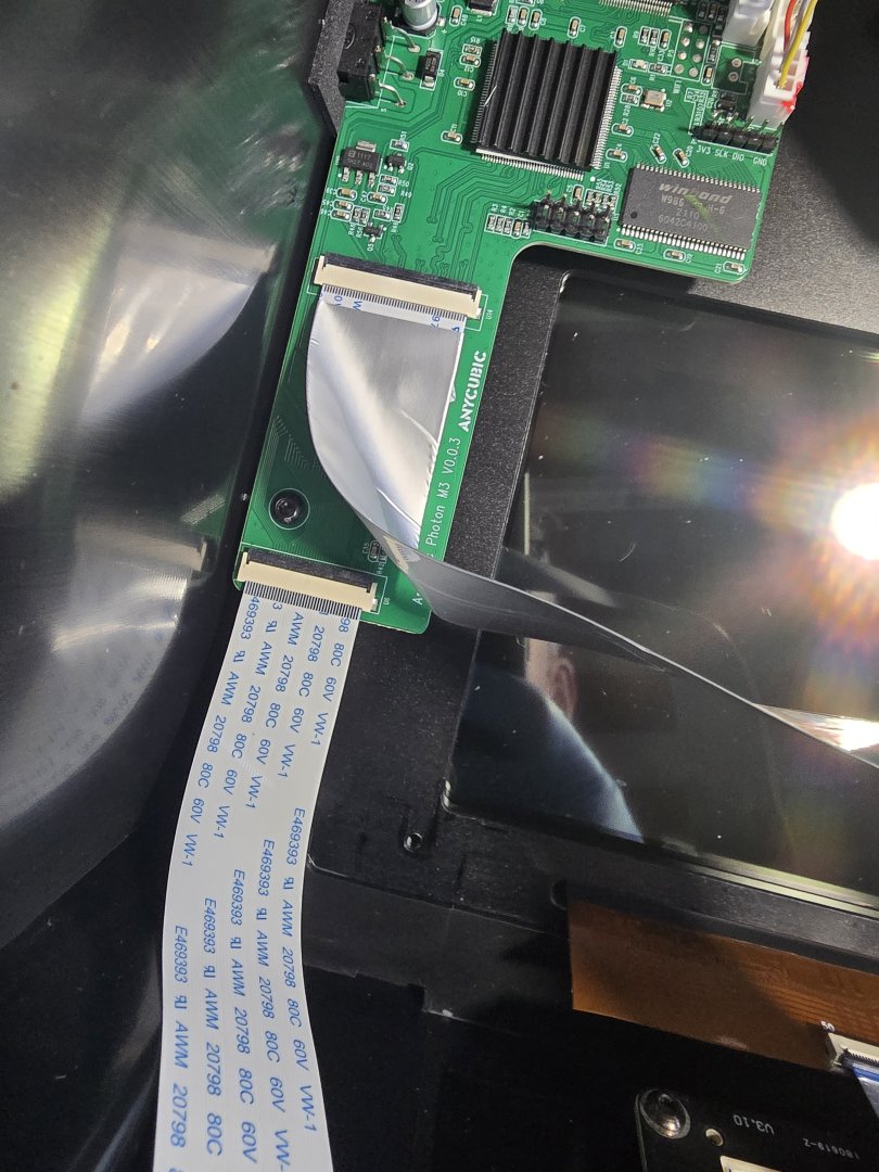
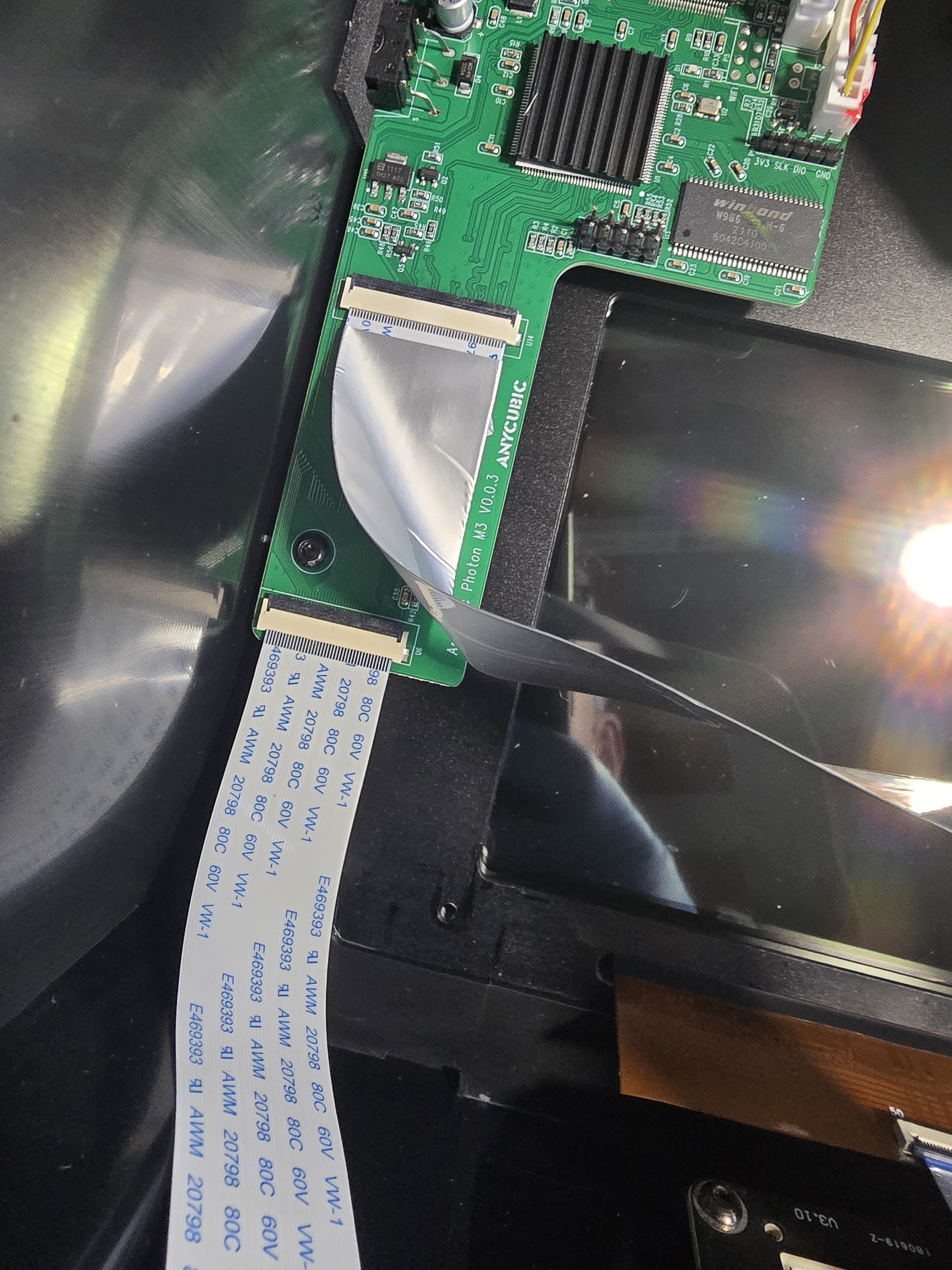
8. Due to different plug in point on the replacement the original printer cable was slightly too short but chitu systems sent a spare cable in the box which was long enough.
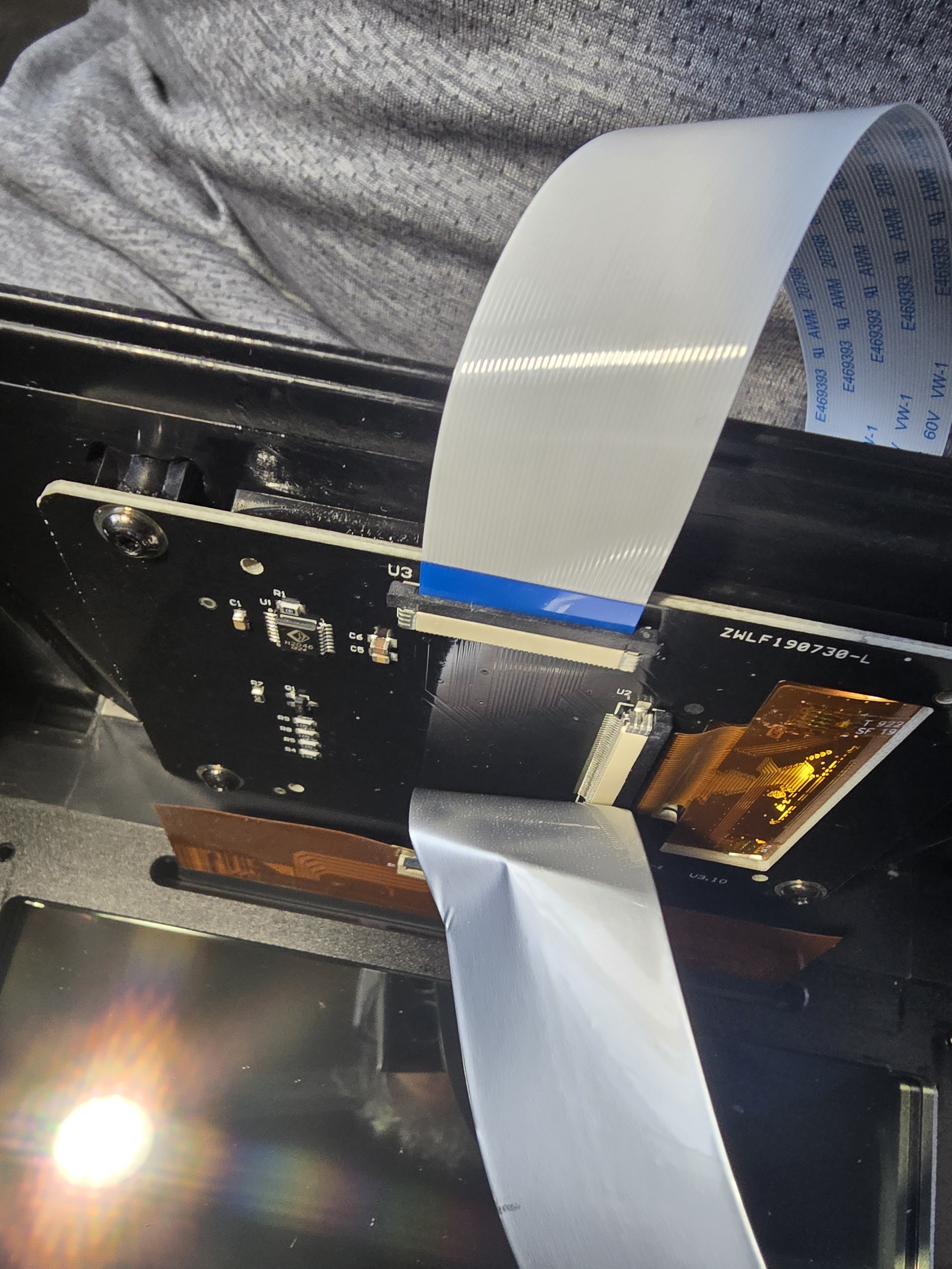
9. Remove original cable and plug in new one. Push black retaining bars back down to lock in.
10. Replace cable guard and tuck all the cables down out of the LCD screen perimeter.
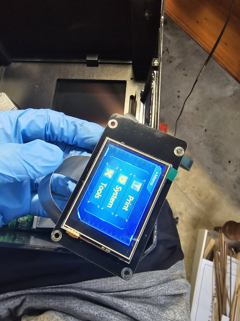
11. Test again all good before base plate placement. Plug in cables and screw down plate.
I left the plastic screen protector on.. it works with it on and gives a little bit of protection from resin drips from the vat
That's it.. all fixed


-
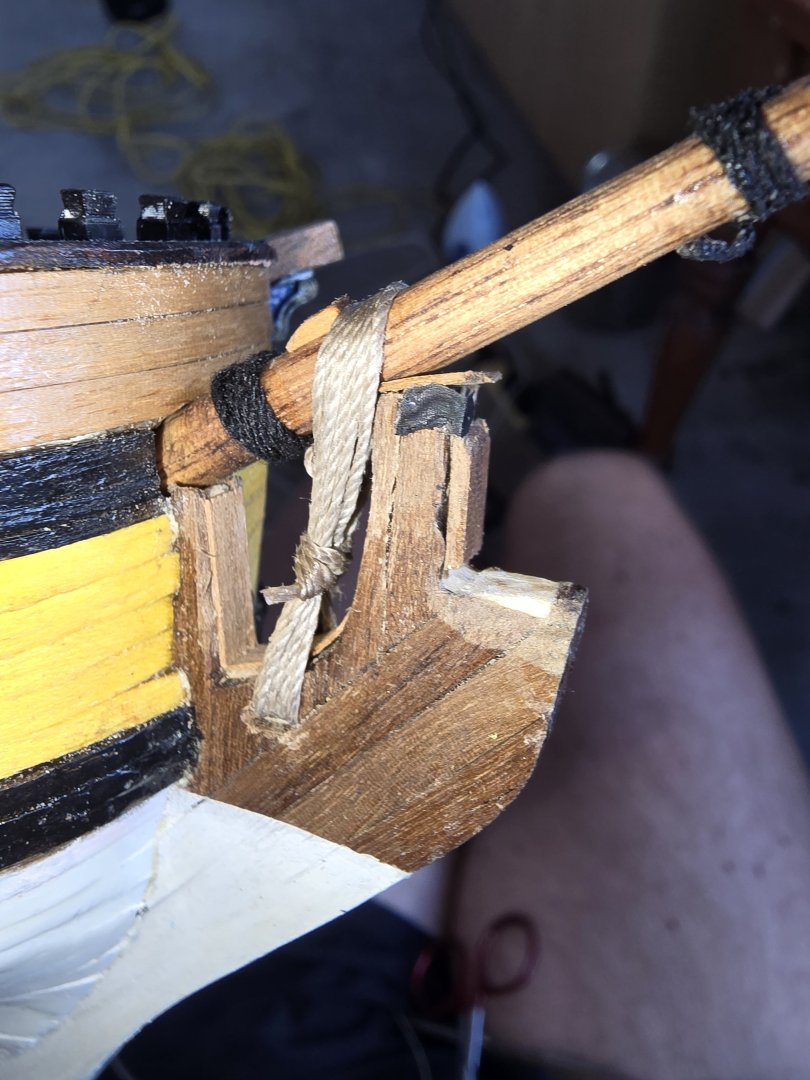
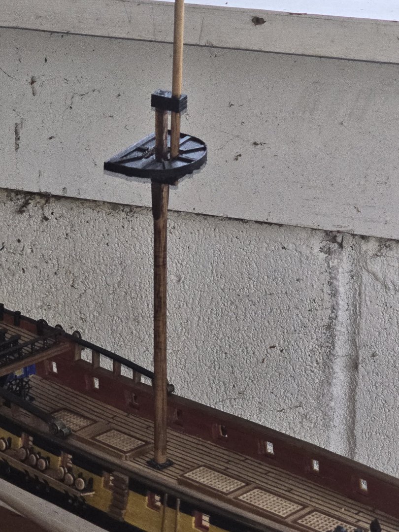
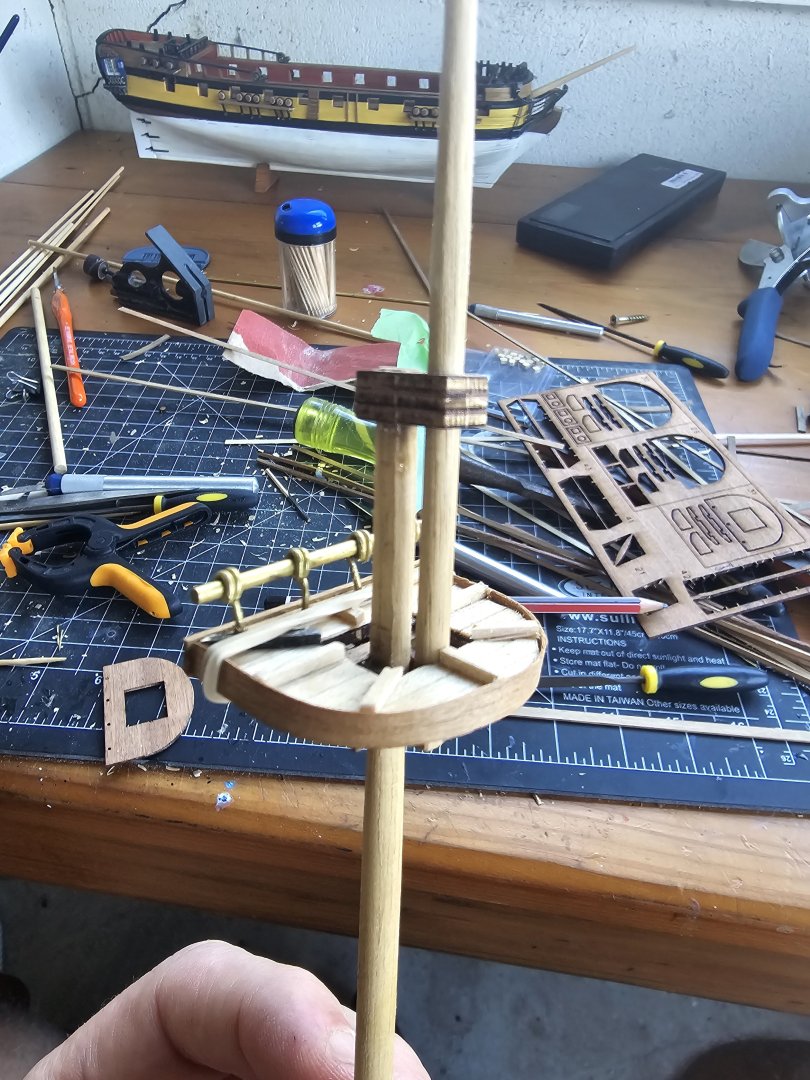
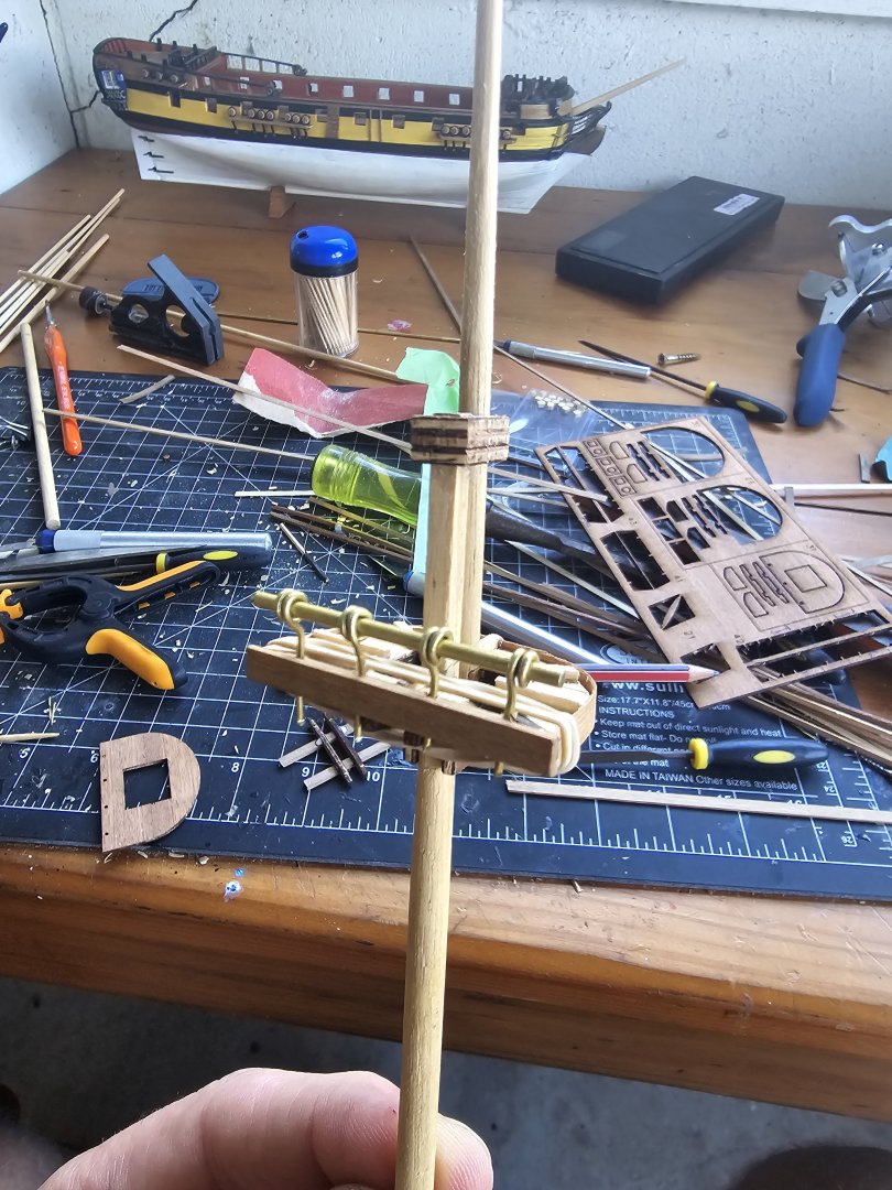
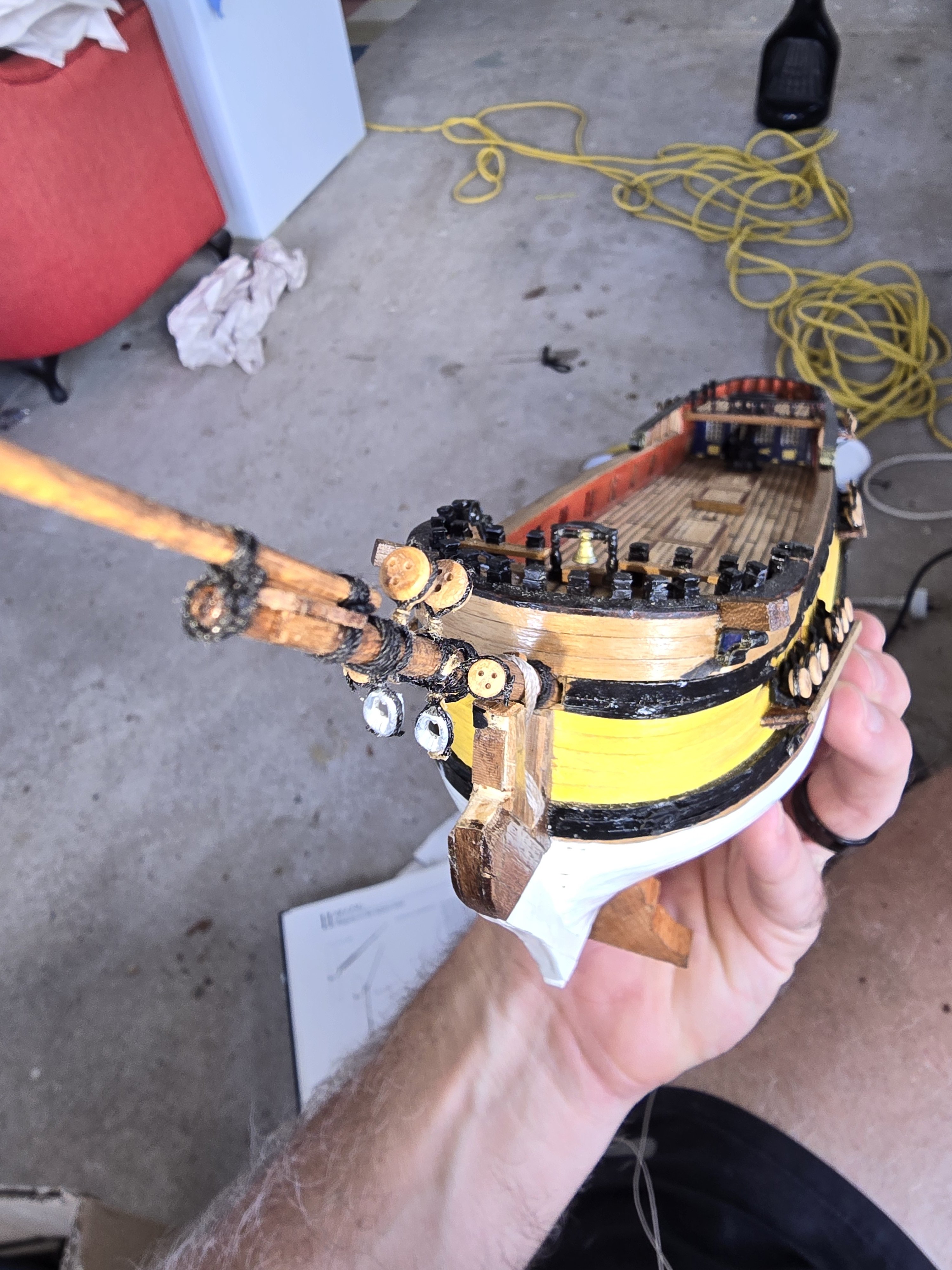
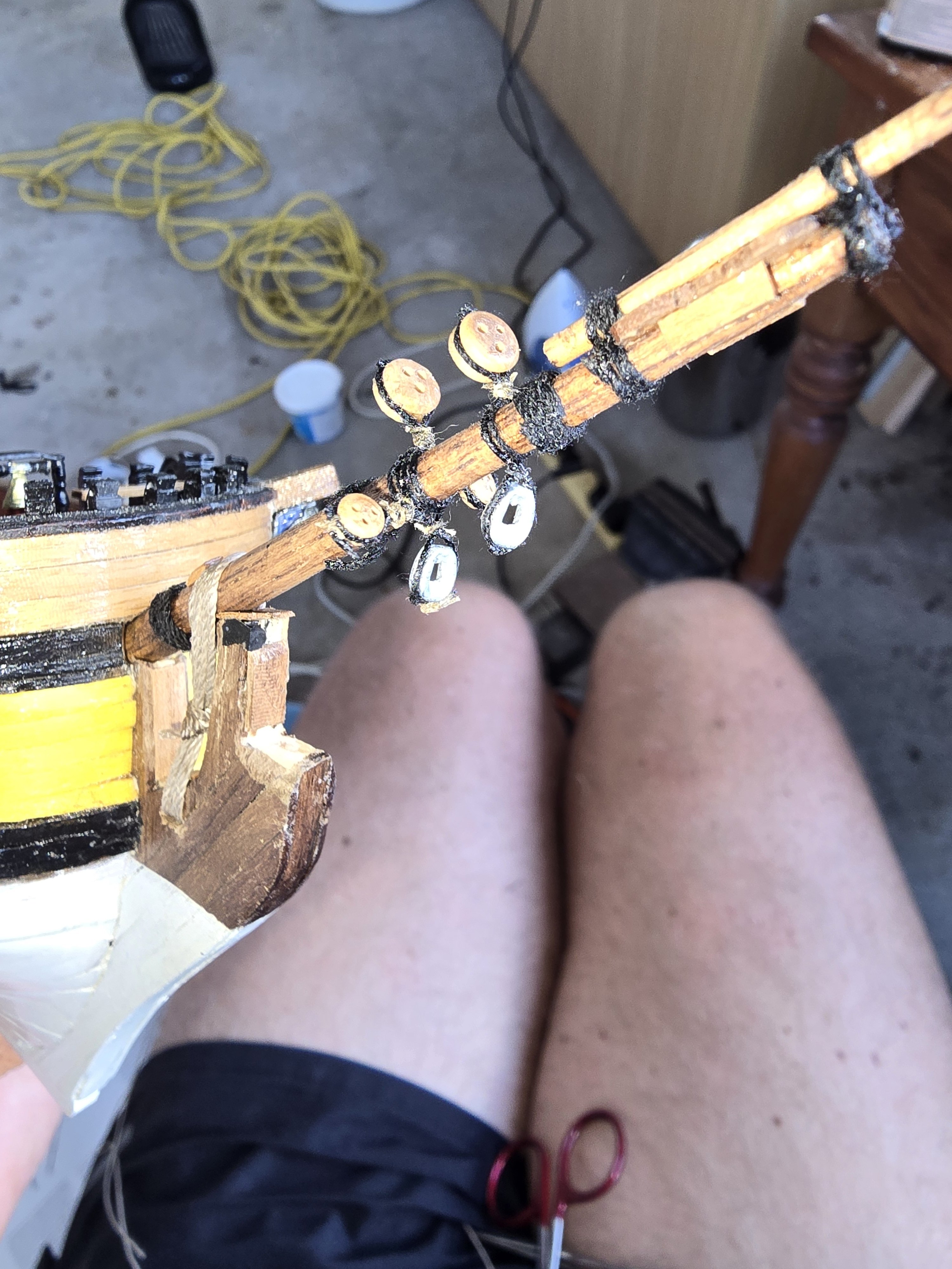
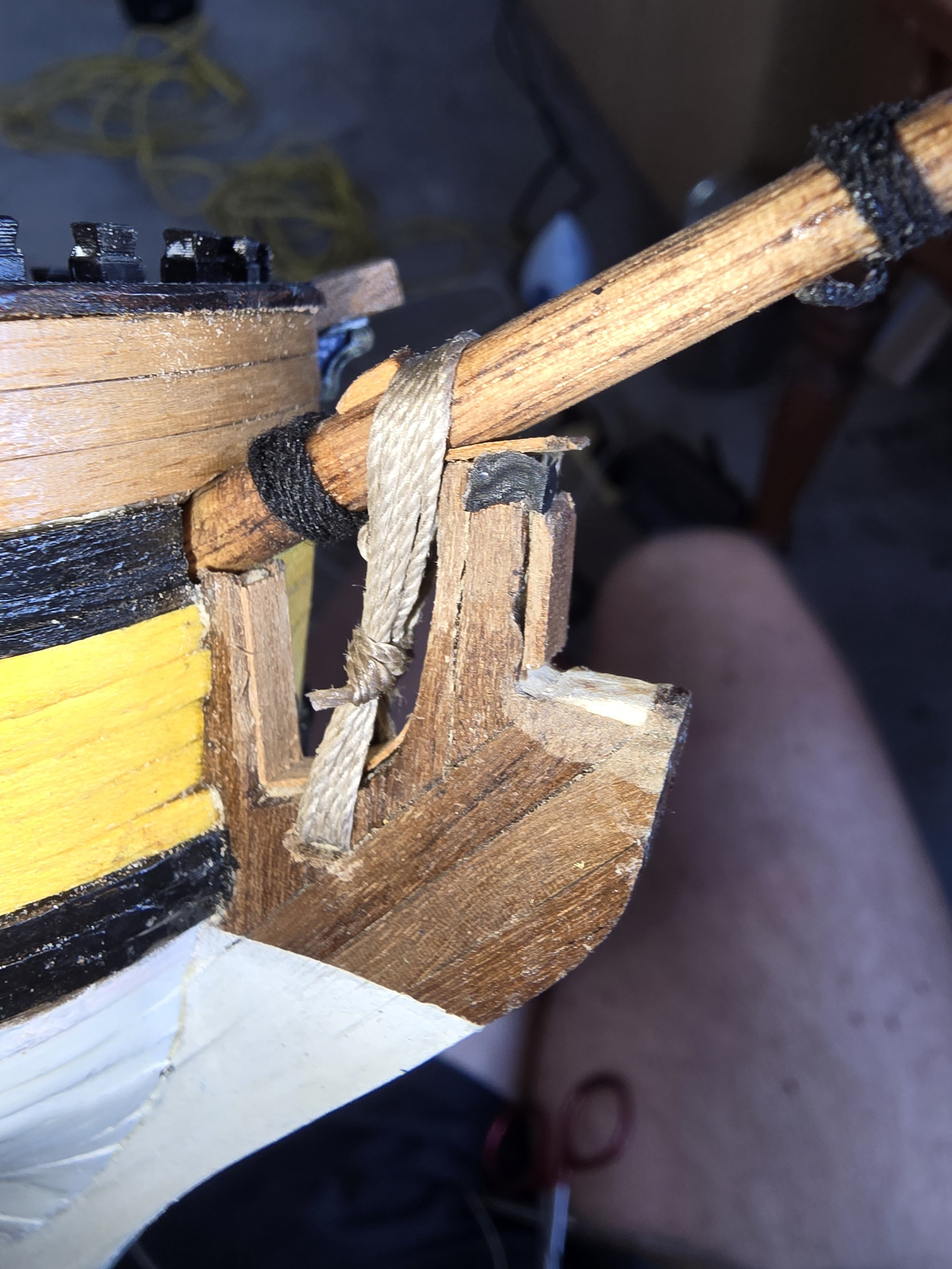
Working on the bowspit collars as per 1719 collar arrangement with the heart blocks on the bottom for the Bobstays amd the deadeyes for the fore preventer stay and the forestay.
Tried my first gammoning and ok with the result.. at 1/100 scale hard to get a perfect knot but happy enough.
Pretty much I'm ignoring the kit rigging plan and just using the lee's book.


-
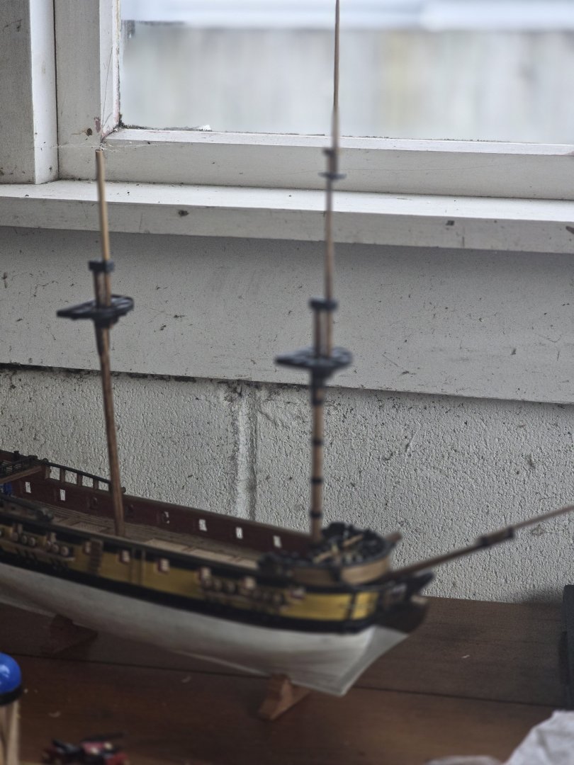
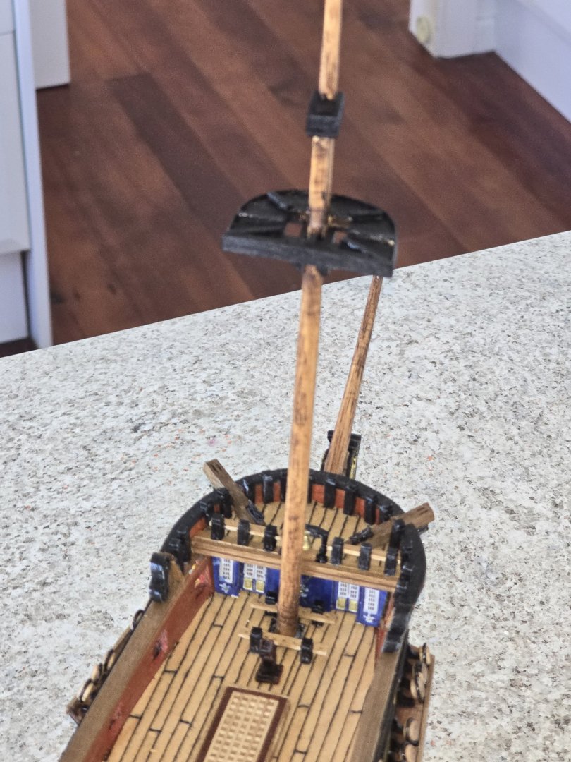
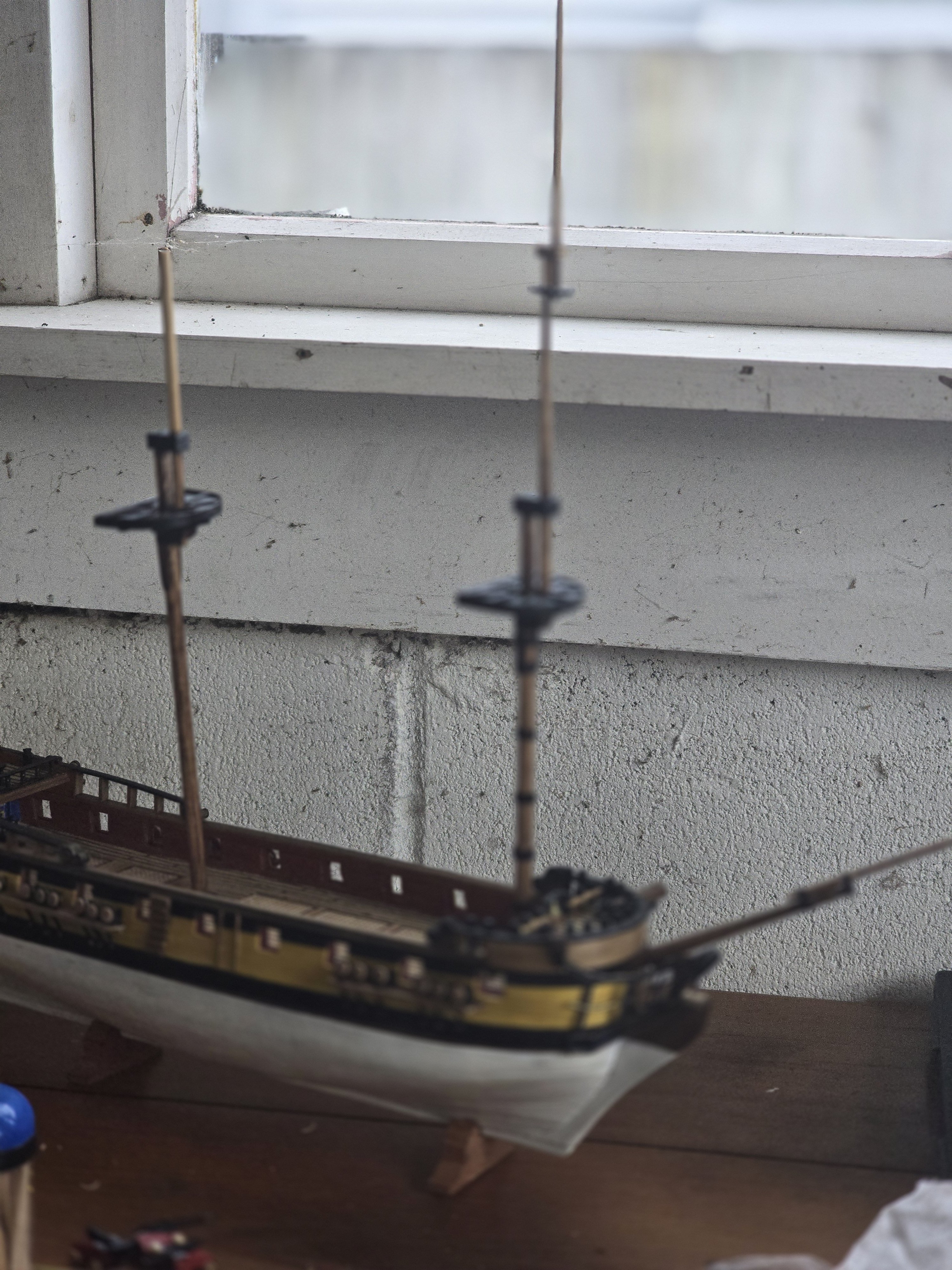
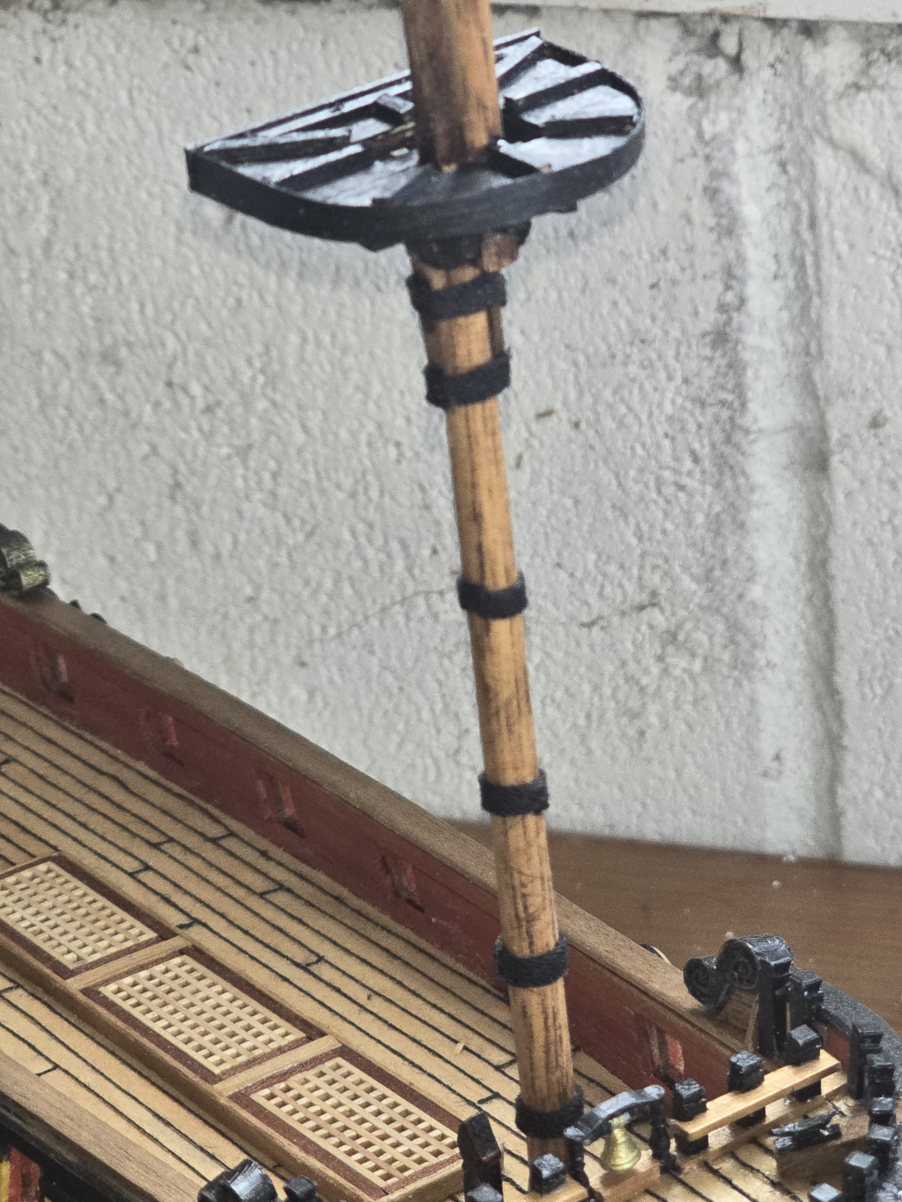
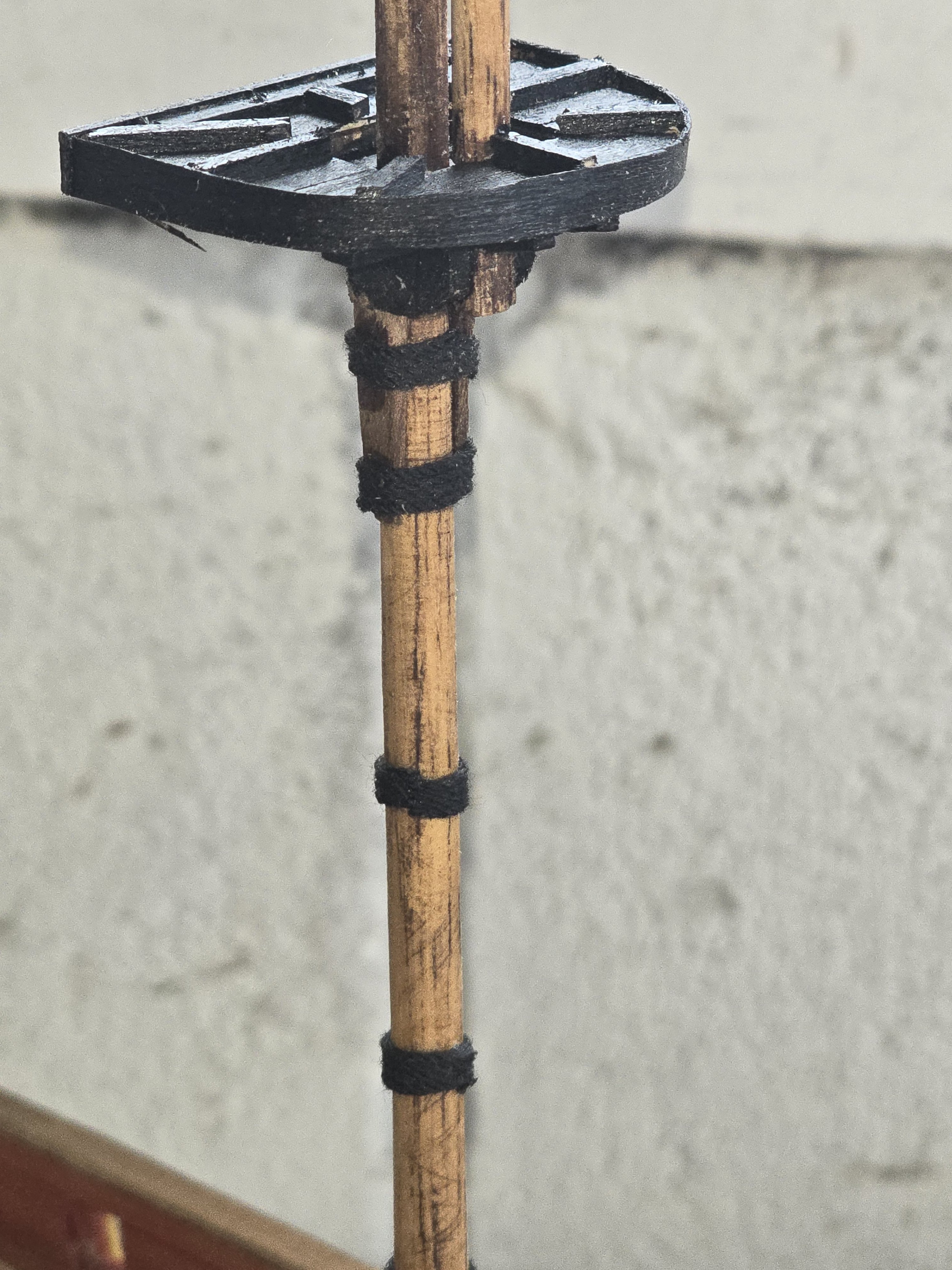
Starting to make progress on the main and the fore mast. The woodlings have gone on thr fore cast and made the main top.
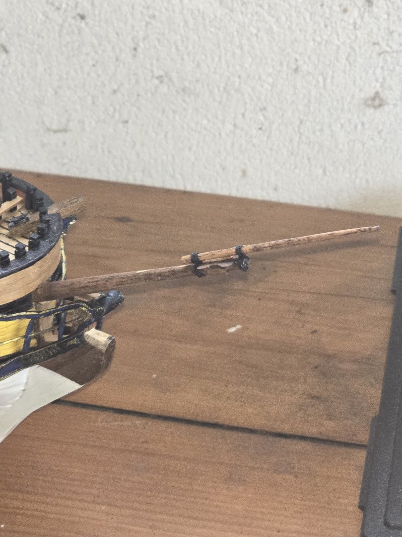
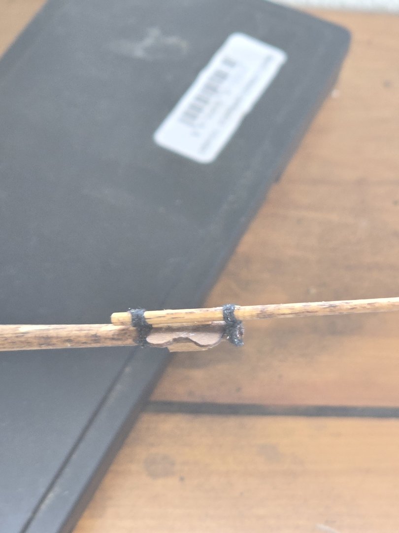
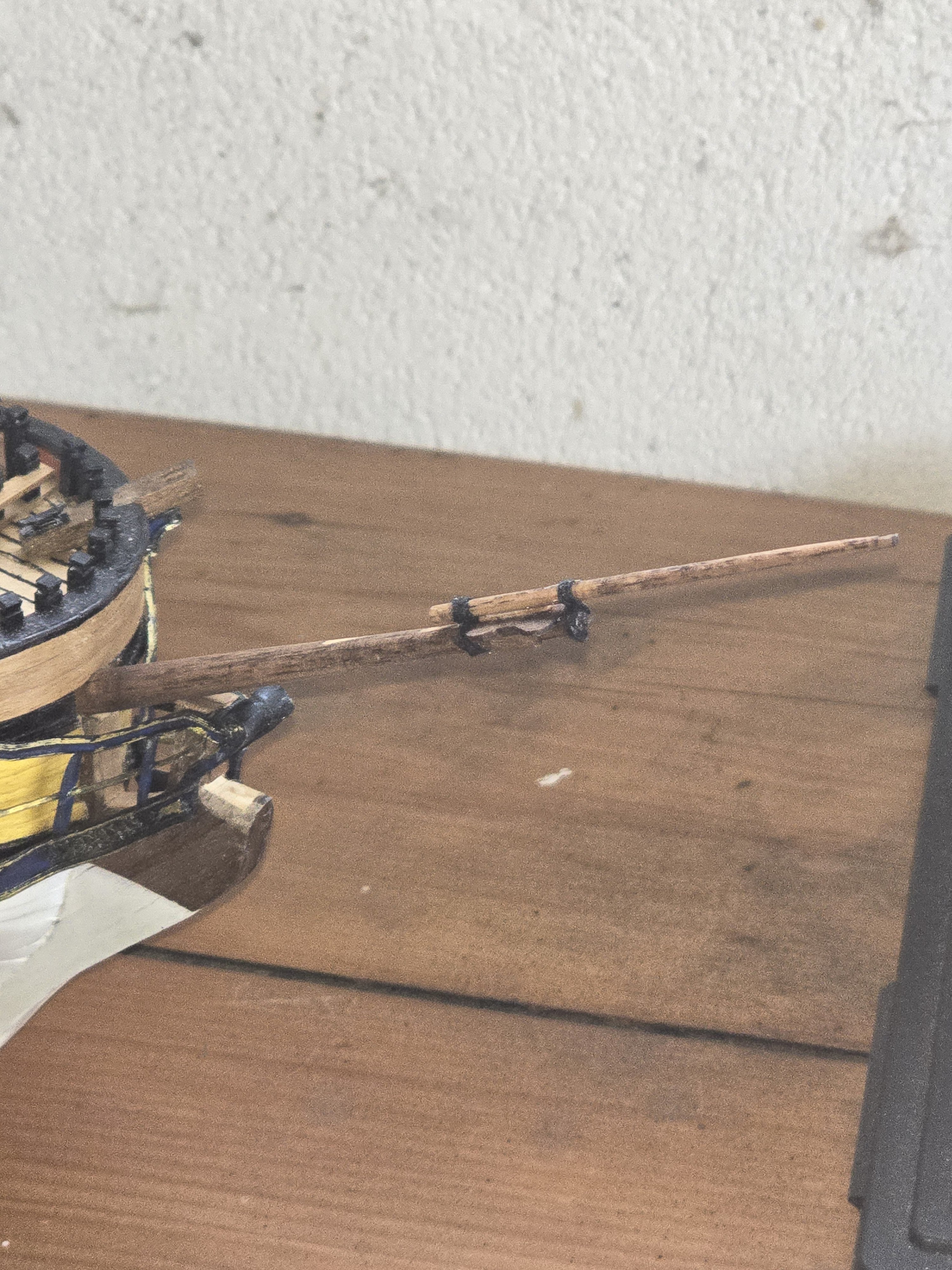
Have put bees on the bowspit and figure of eight lashings on the jib boom. No spirit top on this model.
Next is the woodlings for the bowspit and start the heart blocks for the shrouds.

- Old Collingwood, Gregory and robdurant
-
 3
3
-
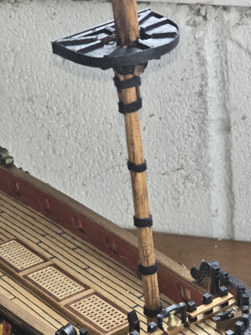
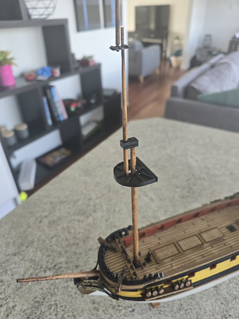
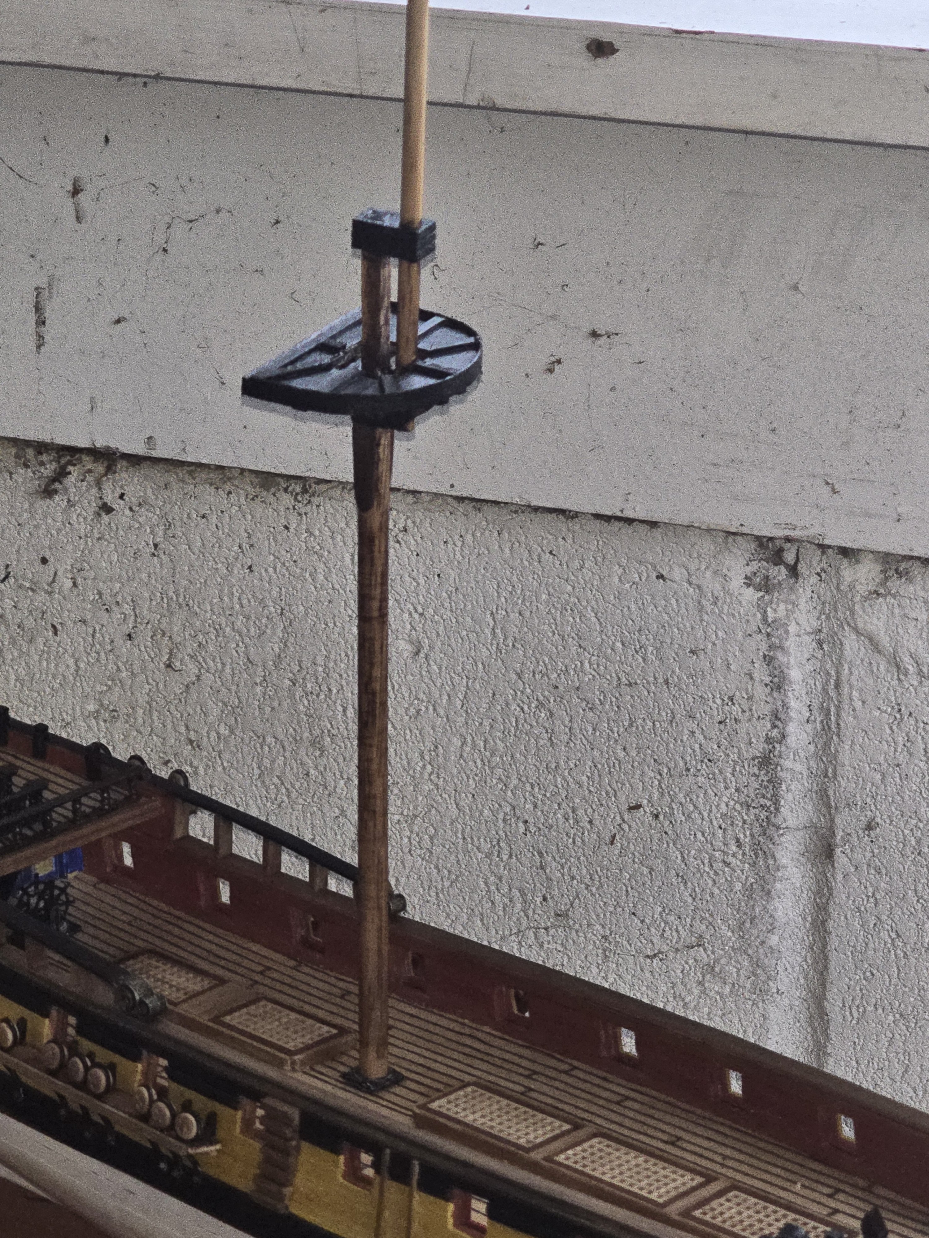
I've completed the fore mast, just have to taper last section. The kit supplied parts take a bit of alteration so that the mast is straight. Have to make the hole in the fore top slightly longer on a bow to stern axis to get the two pieces of dowel straight.
I wanted a aged look to the mast so I used a dark timber stain to bring out the dowel grain. Then light sand. Then used linseed oil to dark the light wood colour.
I'm going to gloss them up with a coat of shellac at the end.
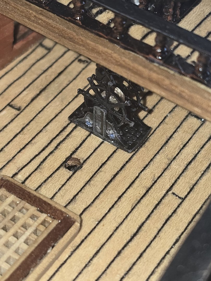
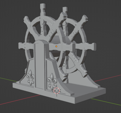
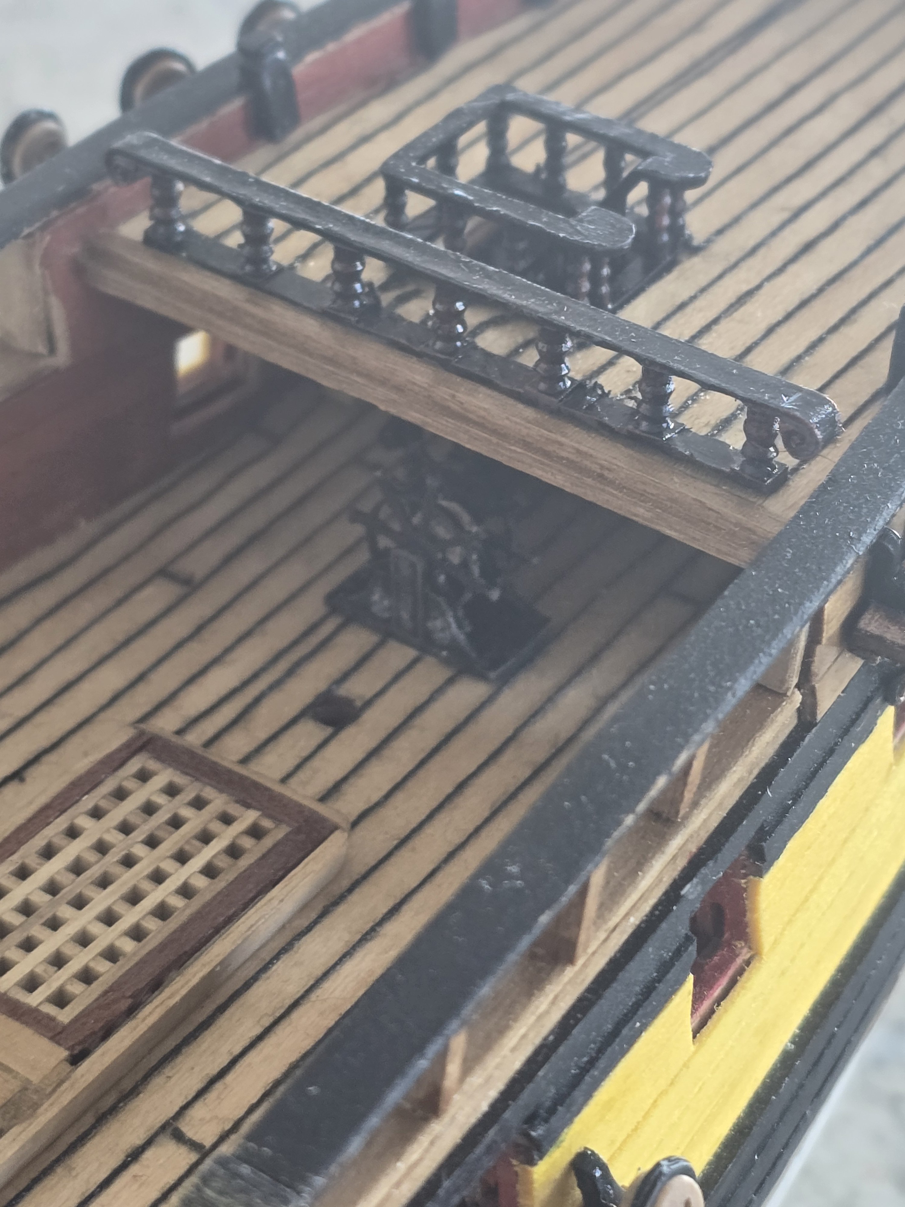
Picture of the completed wheel , 3d printed and painted


-
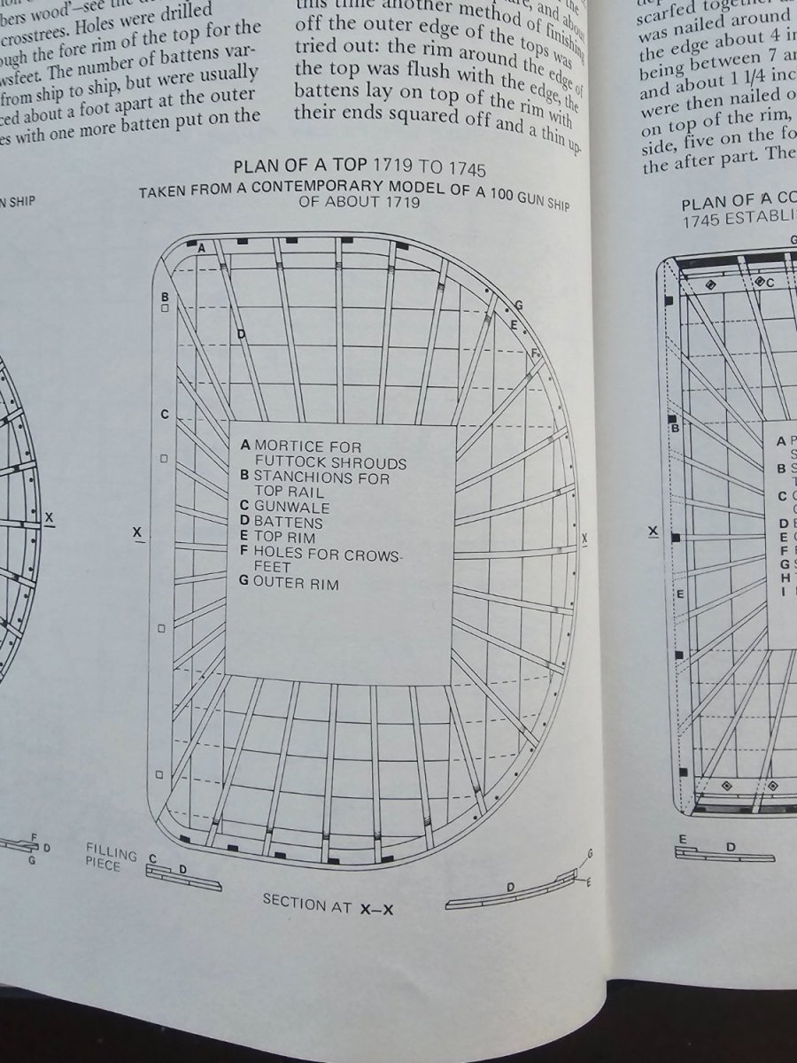
I am moving onto the masts now. The fore mast is nearing completion. I did a brass rail for the fore top but steel iron wasn't used much in 1720 was it. Should it be wooden and say turned ballistrade with rail or can I keep the one I made here?
-
Hi... the rail width is 5mm in figure 9 so the timbers below that need to be less. I think either way is okay... I personally bought extra walnut 1mm x3mm so that it was 3 layers of 1mm equal to 3mm with 1mm overhang at the rail each side to allow the rail edges to be chamfered.
-
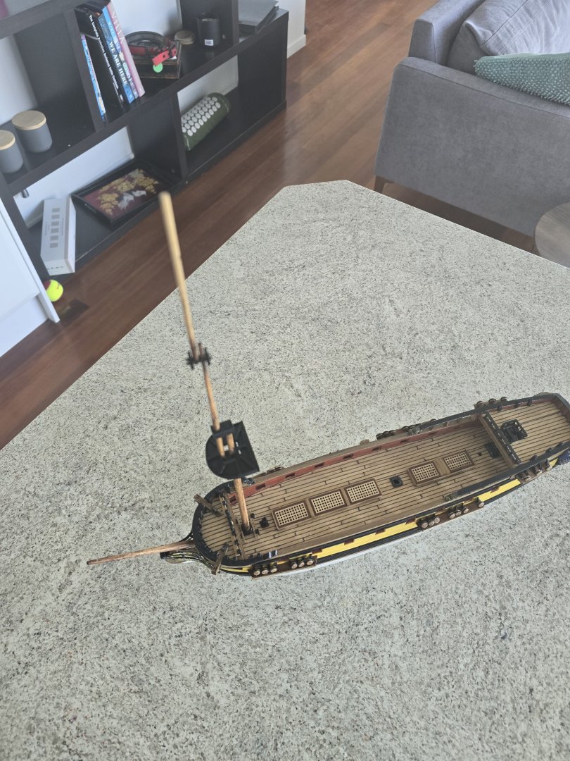
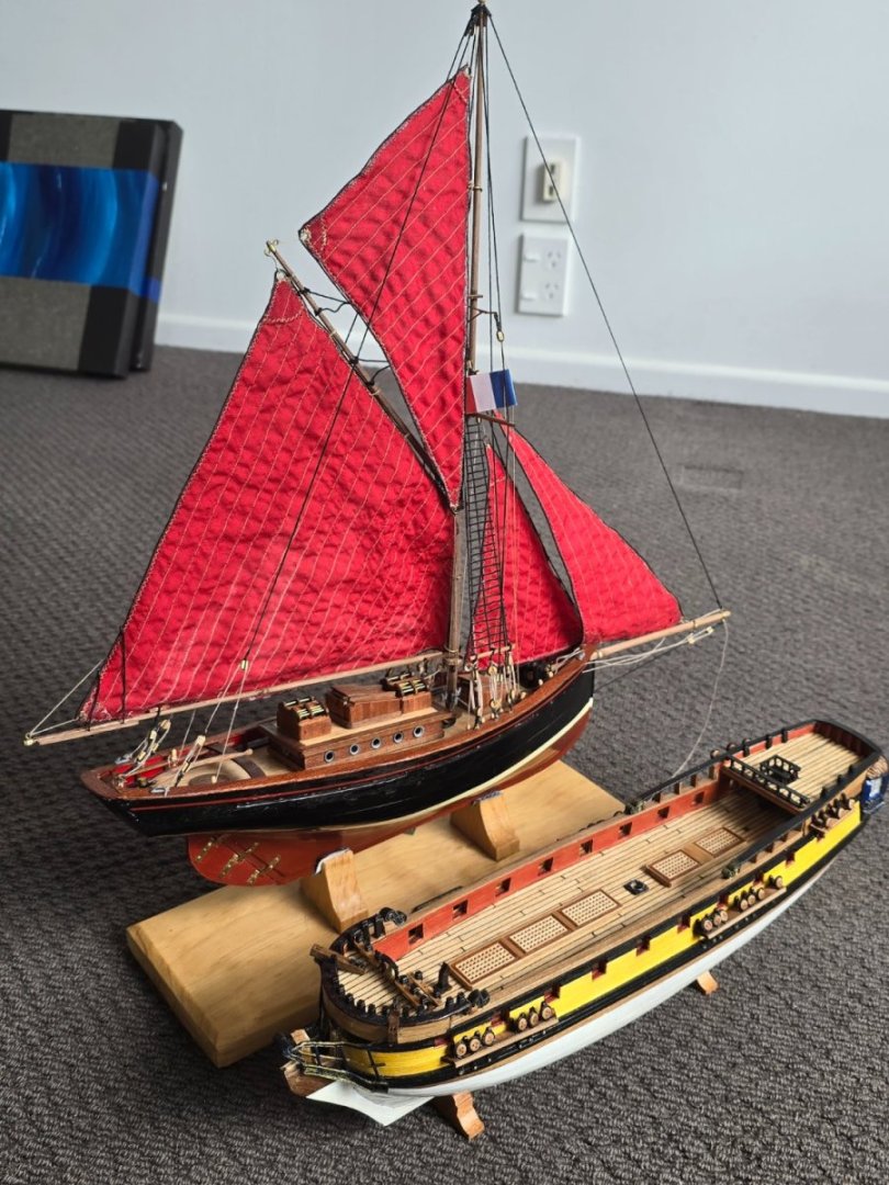
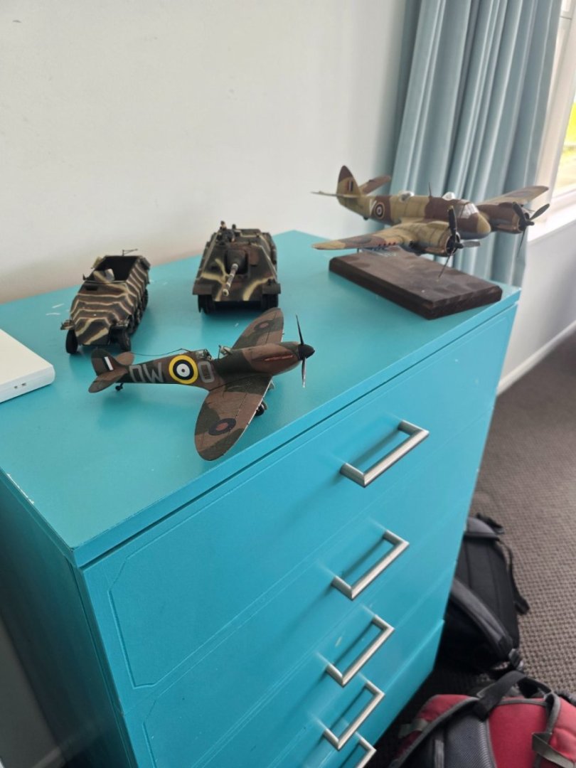
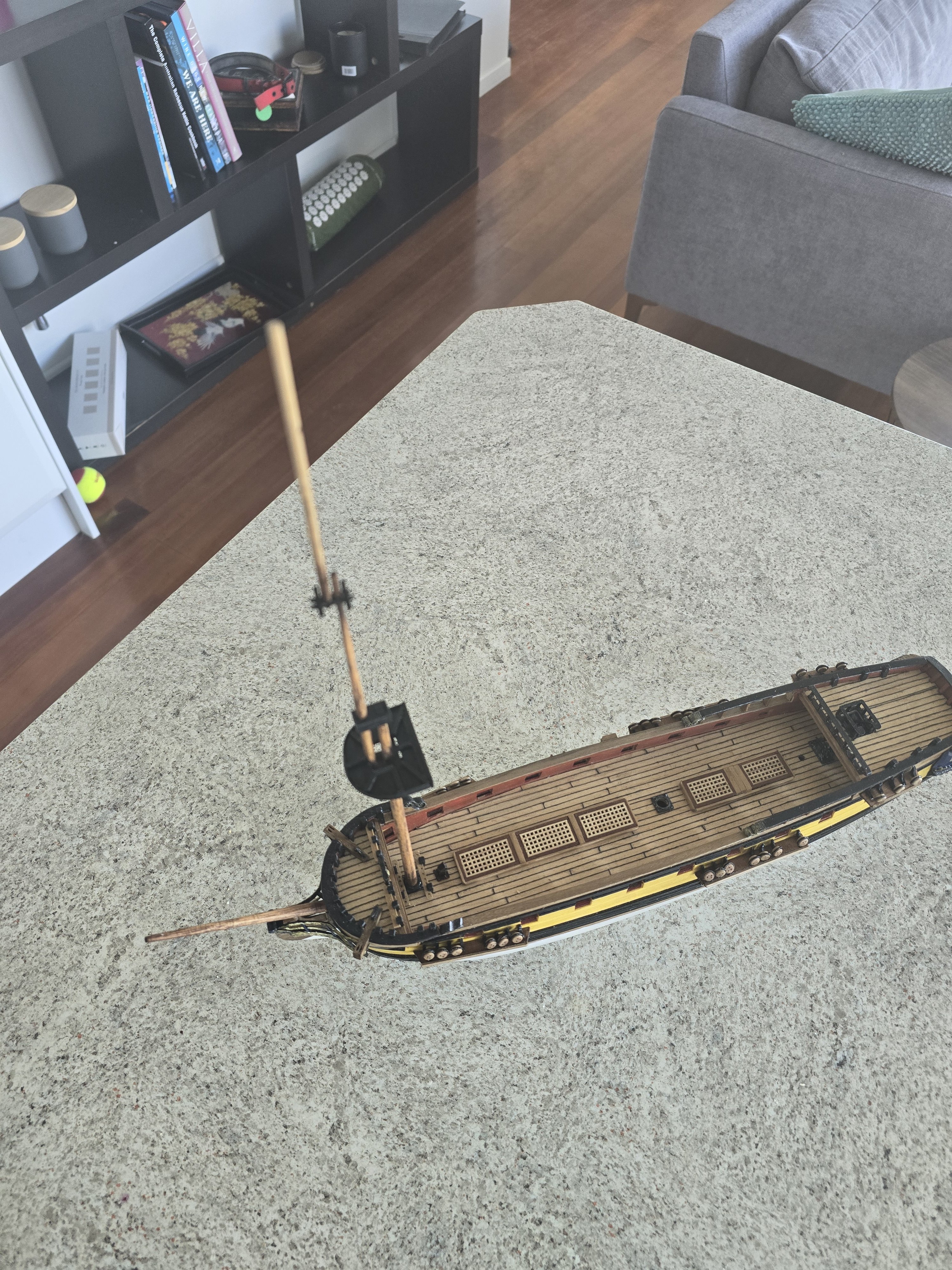
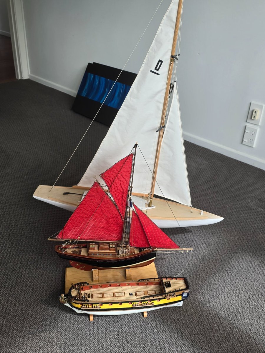
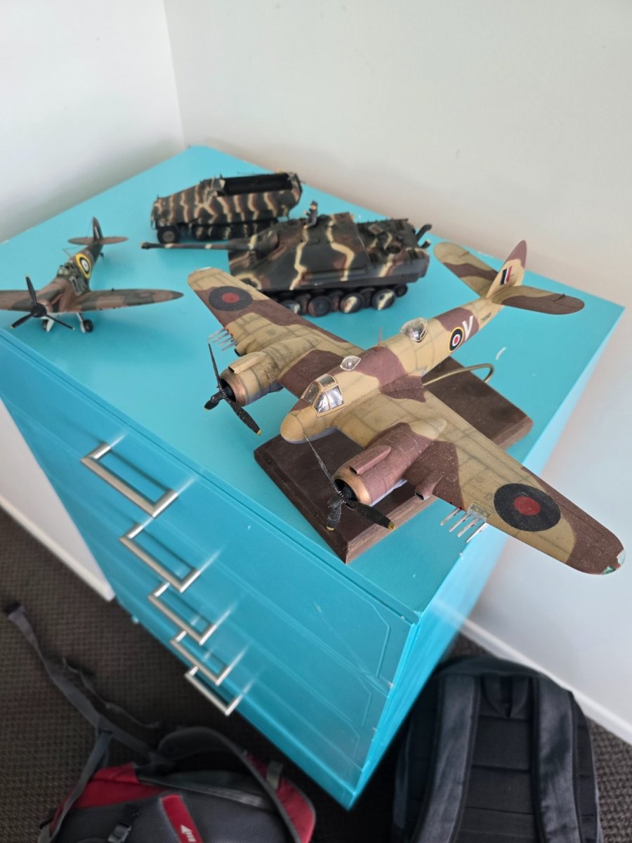
It's always harrowing when you move house and you have to move the current project. Hoping nothing gets broken off or bent. Happy to say the flotilla is back together and all the boats happy.
The plastic models.. a little bit bent.. and need dusting


-
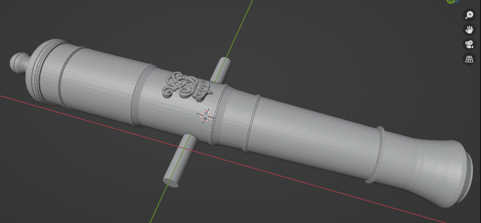
Replacing virtually all the molding's on the kit, I've done a ships wheel based on the picture below. When I print it it will be three pieces and I will glue it together.

-
I looked at this Chinese options @Gregory but the centre to centre distance since there is no pass through is around 200mm. The green machine is 300mm. The mast on the billings drakkon boat was 450mm or so from memory tapered. Some spars I would image on 1/48 scale would be wider than 200mm on older ships.
My concern is you spend $495 dollars and get a machine for a certain job but can then possibly step up to a Chinese lathe/milling machine in the 800 range. A milling machine would be great for the hexagonal sections of the masts or the square sections as they go through the mast cap. But can achieve that with a file and sandpaper as well. Machine choices hard...
-
-
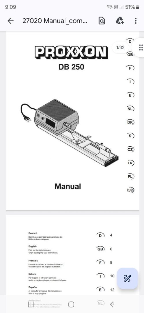
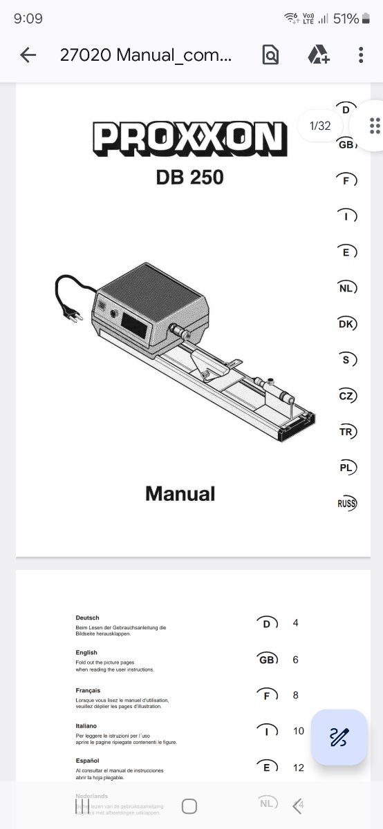
I see some people using the proxxon mini lathe and it comes with collets upto 10mm and quite long centre to centre measurement. What's the verdict on that machine? Price is good too for nz dollars.
Really just want to make a good taper on my mast and spar sections as the old drill and sandpaper method is a bit hit and miss. Yes it's approximately right but want that added machined quality to it and keep the mast sections straight centre to centre.
But it's going to be a hand piece taper and again not a autofeeding or angle feed on this model. Maybe the result won't be that flash.
-
Suddenly the greyhound is the most popular model being built right now
*laughs*
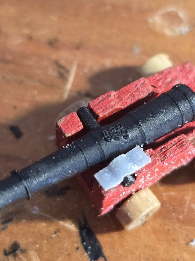
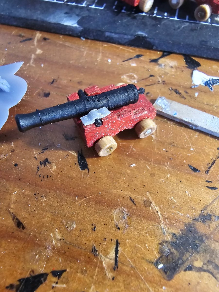
Anyways- instead of bending 40 tiny pieces of brass sheet I did the Cannon bolt plates in the 3d printer. Printed all 40 off in one time. Sweet!


-
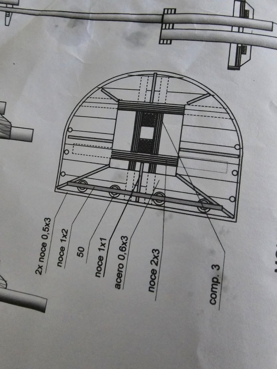
You need to study that cut away section diagram on the plans and think from the outside in to work out what will look good with the rails on the outside, the planking wood and then coming back to the 1mm strip. Once you decide that then follow the suggestion from the deck shape for the runs of those timbers and if need be shim out the bulkheads to get a nice run. I don't think you should cut the deck in back to your bulkheads. Better to build them out. The bh are plywood so can be cut off or sanded back from the inside if required. I covered mine completely so can't see them edge on.
But same thing with deck.. I didn't want to see that plywood vaneer edge on the outside hull so the basswood planks covered it. That's why I recessed that rail in.
-
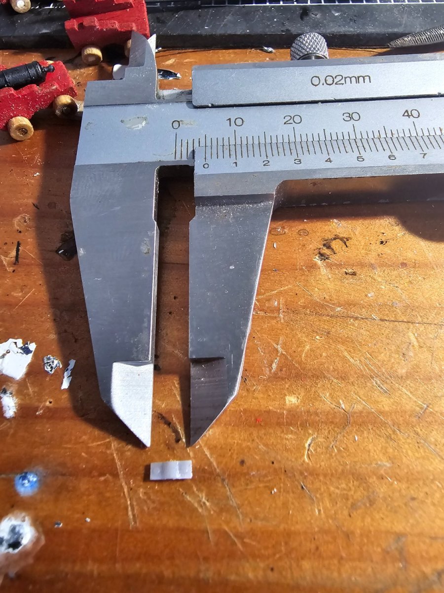
I was going with the top rail width. If the rail is 5mm then the hull needs to be around 3-3.5mm width finished if you want a overhang on the rail of say 1mm each side. So that's 3 thicknesses of 1mm strip to make up the hull to the rail. FYI the timber provided is not 1 mm thick exactly it's about 1.3mm measured using a vernier scale. I think mine came out close to 4mm thick giving a rail overhang of 0.5mm each side
-
-
Hi... I don't think there is enough decking to do the lower deck... although i wasn't that careful and didn't try and minimize the cut off ends... adding up all the small left over cuts might be enough for the lower deck. Can't you just buy 0.7mm basswood strips from a supplier anyway if you wanted more?
-
-
I cut down the tops of the bulkheads after I made the bottom section fit better and also drew that line on. And that's where the planks will rebate into the keel along that line
- tennfox and Old Collingwood
-
2
-
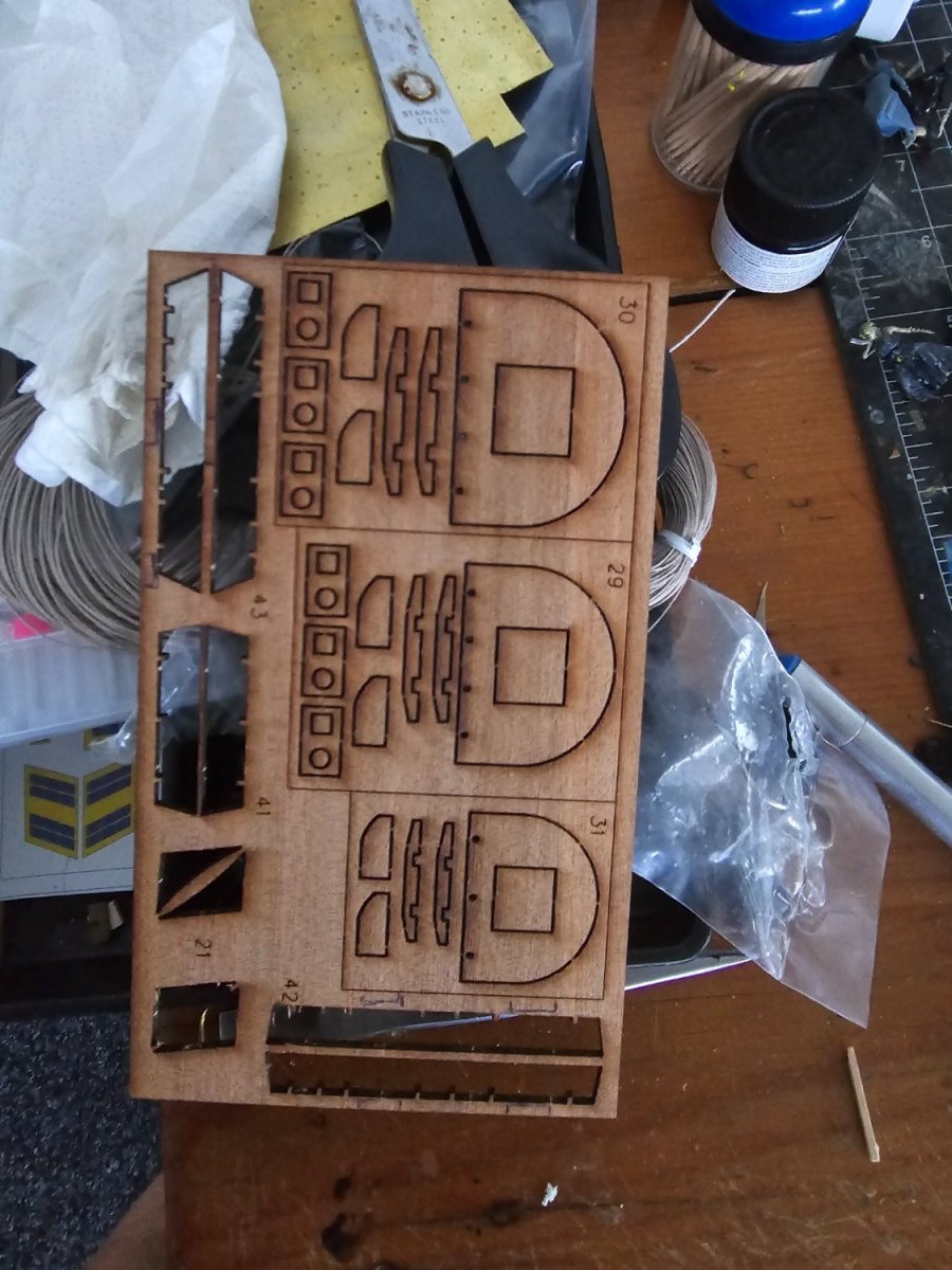
11 looks a bit too deep. Move up a little
-
Yes they should... just make the slots a bit deeper so it sits lower down. How much are you out by?
-
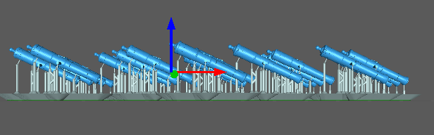
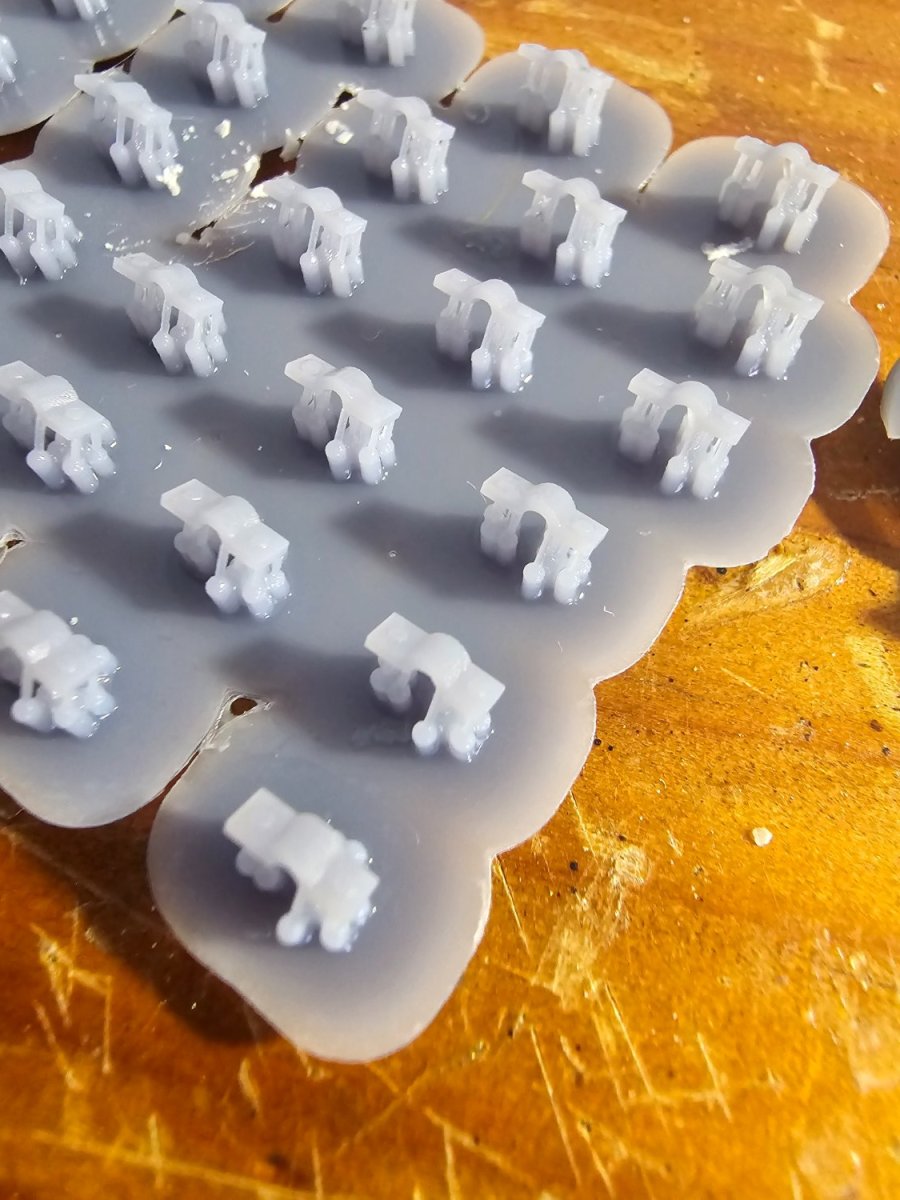
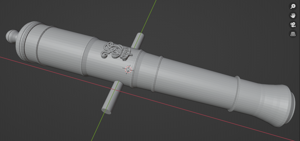
Quick question barrel tilted down away from the build plate isn't it... not towards it
- thibaultron and mtaylor
-
2
-
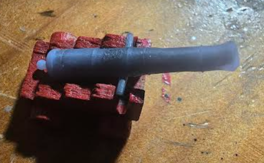
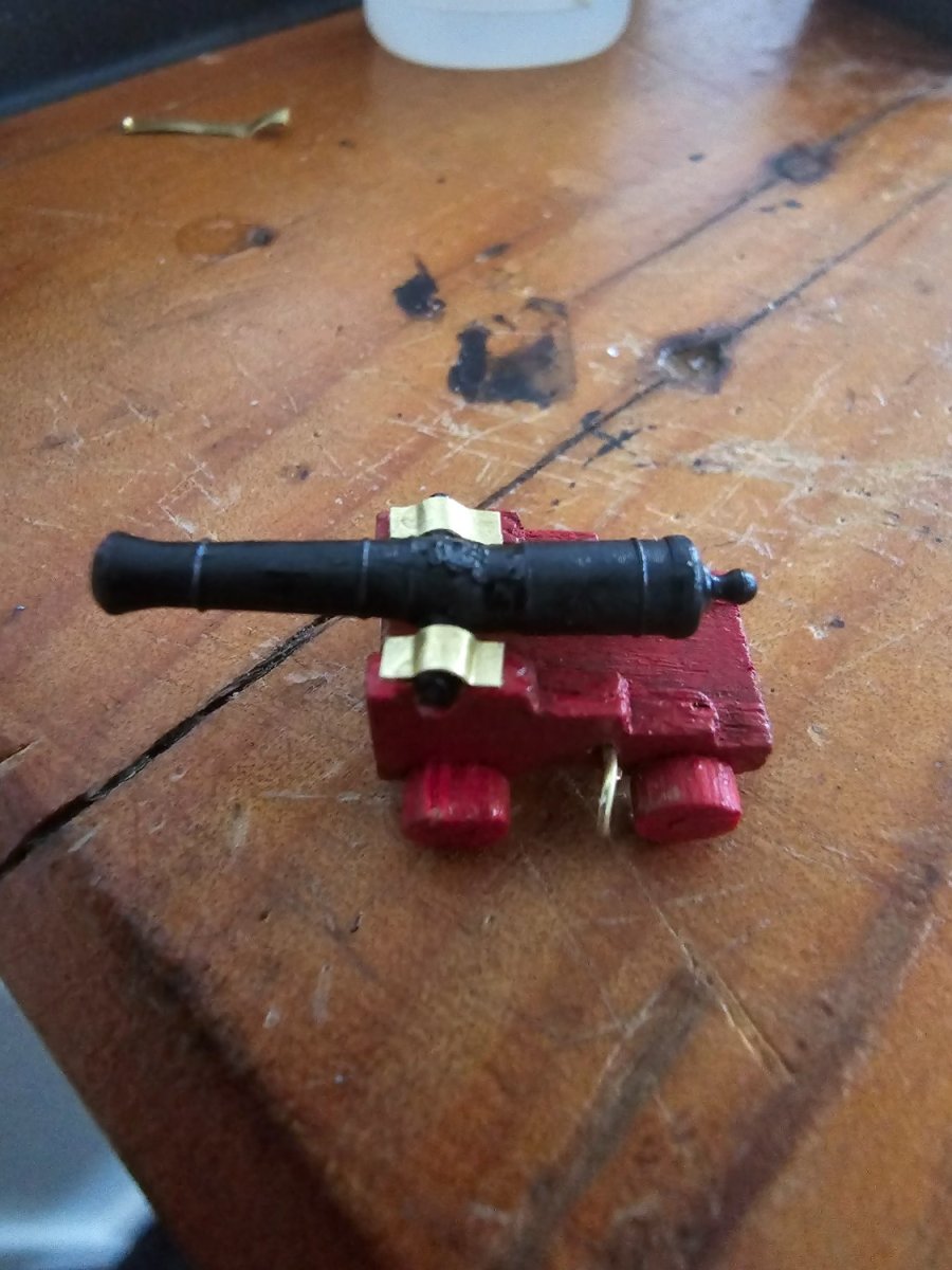
I printed off the armstrong pattern 6 pounder 84 with the george 2 cypher and had quite a few print fails across 20 barrels. Wondering if the resin temp was a bit low - it was only about 22 degrees today. Anyway - some of them turned out ok. Should I tilt the barrels further when I print?
- mtaylor, Seventynet and thibaultron
-
3
-
-
Have you got the similar table for a pattern already done like a Armstrong 6 pounder 72 to help me work out what goes where?
- thibaultron and mtaylor
-
2


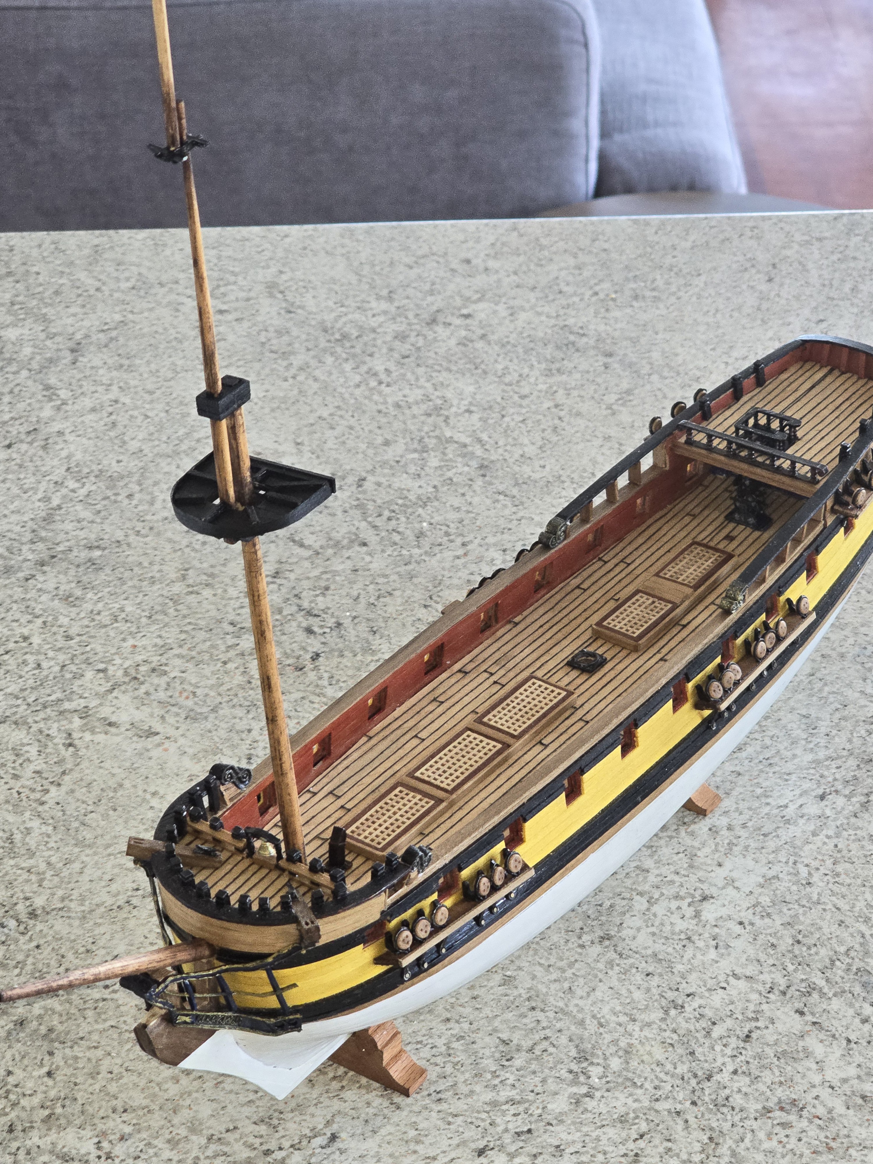


HMS Greyhound by Srenner - Corel - 1:100
in - Kit build logs for subjects built from 1501 - 1750
Posted
Taking a break from the model ship building and visited a beautiful happy place, Greenwich UK and the maritime museum.
Loved the displays and lots of beautiful ship models here. Absolutely gorgeous 😍
Plus the Cutty Sark , what more could you ask for?