


Jaager
-
Posts
3,084 -
Joined
-
Last visited
Content Type
Profiles
Forums
Gallery
Events
Everything posted by Jaager
-

HMS ANSON 1781 by albert - 1/48 - 64 guns
Jaager replied to albert's topic in - Build logs for subjects built 1751 - 1800
HMS Anson 1781 second group of the Intrepid class 64 gun 1st class Intrepid 1779 1771 Monmouth 1772 1778 Defiance 1772 1778 Nonsuch 1774 1776 Ruby 1776 1778 2nd class Vigilant 1774 Eagle 1774 1776 America 1777 1778 Anson 1781 Polyphemus 1782 Magnanime 1780 Sampson 1781 Repulse 1780 Diadem 1782 1783 Standard 1782 This class is one of the more documented designs ZAZ 1486 lines L37 J3635 1487 frames 45 3682 1488 inboard 1489 orlop 1490 GD 1491 UD 1409 orlop 34 3242 1410 GD 34 3241 1311 UD 34 3240 1412 QD/FC 32 3239 If no print has ever been ordered and is not in stock: no price The NMM wed site has the J# but does not identify them. -
Split ring making process
Jaager replied to Dave_E's topic in Metal Work, Soldering and Metal Fittings
There is a shop note - I have not saved the author's name or journal reference - but he got a much longer life from his disks by coating one side with epoxy glue - I think the watery clear flavor epoxy. -
Split ring making process
Jaager replied to Dave_E's topic in Metal Work, Soldering and Metal Fittings
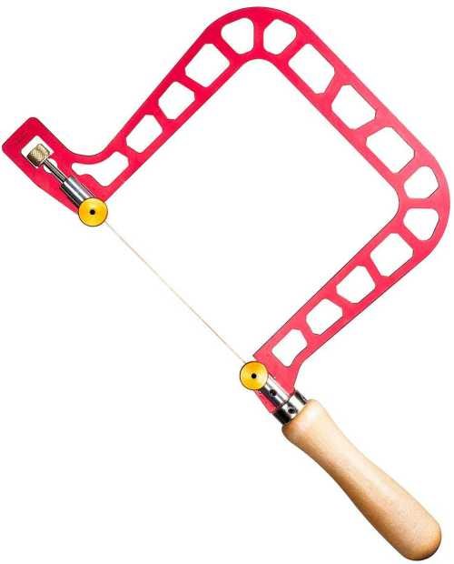
The technique that I read and stored in memory: a drill with a shank diameter equal to the inside diameter of the rings brass or copper wire that is the diameter of the ring body wrap a tight coil of the wire around the drill shank saw the coil = lots of open rings solder I am wondering if a resistance solder machine would play nice for this? A plot devise in "Crash and Burn" had a primary character go loony from breathing the heavy metals in circuit board solder - so I good ventilation with soldering may be prudent. Copper and brass are ductile - with a jewelers draw plate, theoretically one fat wire can be drawn down to any diameter desired. There is more to it than that - for brass at least - working it causes it to harden - it gets harder to pull Heat will harden Fe - I think heat will soften brass and maybe Cu? -
To explain my answer: That the question was even asked and the way it is phrased indicates to me that the OP is a relative beginner. My process has no function for a scroll saw - I use a 9" bandsaw for my scroll cuttings -I do not need to get close. I did buy a scroll saw long ago - the economy MM. It is terrible. Were I to need a scroll saw, I learned that it needs to be a quality machine - not one that fights you all of the way. The OP should get far enough into this to have a good idea which machines he will need before an expensive machine is purchased. The time spent using hand tools will be a low cost if he decides that all this is not for him. If he buys an expensive machine and then bails, the winner will be whoever gets an expensive saw at low cost from the garage sale.
-
You are using terms for the parts that are more appropriate for POF. This gets you into a whole nuther world of tools. You are asking about the keel as well as asking about cutting out frames (not really a POF function - the keel is a long stick and frames come from timbers). I will guess that you mean the spine and the moulds. These are POB components. The answer here is low cost and simple. Except that my examples are the expensive options of the tools:
-
Read this: In New Member Introduction New and need help to identify a mystery model? Read here first! (sorry - I have poor skills in capturing links) Unless your great grandfather worked in a starving artist workshop in the wreckage of post WWI Germany that was turning out these items aimed at a tourist market, I doubt that you are related to the actual builder. To repeat myself: "What you have there is decorator kitsch. It is not a ship model in any meaningful definition of the term. It is something that sorta looks like a ship - from a distance, in dark light, thru a gauze curtain, if you squint. That said, it probably has value as its own thing. I doubt that the value involves much money, but as time passes, what was once one of many copies will become more unique. If collecting kitsch as kitsch ever becomes a thing, who knows?" New member Introductions Need Help Identify Model Battleship / Recently Saved From The Curbside (sorry - I have poor skills in capturing links)
-
Looking for suggestions for a good pin pusher
Jaager replied to Capella's topic in Modeling tools and Workshop Equipment
For most of the past - I use curved Kelly clamps - the direction of the force is oblique to the wrist - which is not ideal. Recently, I have found this MM tool to be useful: At Micro Mark the name is Pin insertion plier In general it is best to pre-drill a hole that is the diameter of the pin in the plank. In a frame, a hole that is a tad smaller in diameter does better at holding. For a POB mould - that is end grain plywood - a hole is probably not necessary - end grain is all holes anyway. A pin probably should not be used as a nail on a scale model. The bulldozer - blunt force trauma - friction hold holding action is best avoided.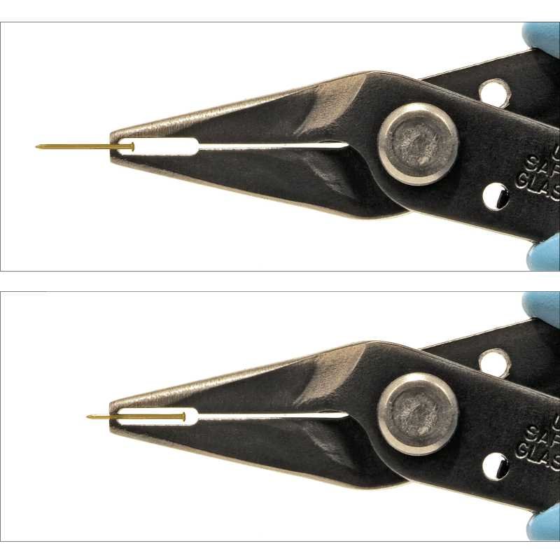
-
Your wooden kit progression - go big, or keep learning/practicing?
Jaager replied to Esap's topic in Wood ship model kits
This is probably about as unique to each person as it gets. Thinking about it - two of the broad groups probably are: Those whose goal is to build an impressive model for display and then move on. They probably have an unrealistic preconception that wooden models are similar to plastic - just with different materials. Those who are interested in ship modeling in general. No one particular vessel is their raison d'etre. Some of the first group become converts to this second one. Starting small is a wise approach for both groups. Most of the first group probably do not accomplish their original objective because this realm of ours is far more complicated and involved than imagined. Any kind of rule of progression thru difficulty level would probably not mesh with their degree of patience. For the second group, the journey is purpose. Moving up to a difficulty that exceeds skills - probably attenuates most of the first group. For the second, it just means shelving the difficult project and selecting a less difficult one. -
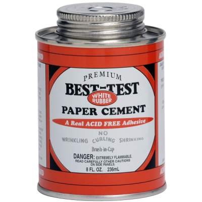
I believe back in the era when things were fast and loose - when diet pills contained live eggs from tapeworms - What? they worked! - shellac thinner was methanol - wood alcohol. Now it is 95% ethanol - with an emetic additive to make it tax free. Shellac has been listed as "cut". One pound cut is 1 lb of flakes per gallon of alcohol. The amber version is saturated at 3-5 lb cut - I forget which. I just read that Zinsser premixed is 3lb. The darker the color, the more wax. The wax increases the solubility in alcohol. I believe super blonde flakes saturate at about 1.5lb cut. For a first coat - there is better penetration if the concentration is 50% saturated (1:1) alcohol to dissolved shellac. Until shellac is something that you are comfortable with - it is easier to use the pre-mixed. Get a Qt. of shellac thinner too. Amber if it is painted over or the natural wood wants "warming". White if minimal effect on the existing color is desired. For all practical purposes 95% ethanol is as water free as you can get. Shellac thinner is less expensive. Pharmco grain from the ABC store will work just as well (190 proof = 95%) if you want to support state and Fed governments by paying taxes you don't need to pay. If you come across a deal that seems too good to be true, there is probably a higher water concentration. I have been wondering if moonshine would work. I distilled ethanol long ago - the 95% comes out of the condenser as much smaller drops than water. But I am thinking that moonshine has been diluted or distilled with less care? Doing the job that they do - already indicates that questionable ethics are in play -so dealing with a moonshiner is false economy.😉 Both, shellac and ethanol are natural products - brand is pretty much irrelevant. "If you come across a deal that seems too good to be true, there is probably" something involved that you do not want. For flakes - right now I like the 1/4 lb bags from Lee Valley. I am of the hope that the garnet flakes will have a pleasant effect on my Hard Maple - like adding 200 years to the look.
-
@alross2Pardon the intrusion but perhaps you should consider adding some tags at the top: Oregon Bluejacket Great White Fleet ? I have an old'er book The American Steel Navy 1972/1989 rep - There are some interesting subjects in the Appendixes.. The Mariner's Museum has( or used to have ) a lot of models from the transition period from 1860 to 1914. Most are so ugly that they are beautiful.
-
I have been singularly focused on aniline wood dyes. Until recently, I have been stuck on the deeper penetration of the water base dye. Now, I am thinking that at model scale, the difference between alcohol and water depth is insignificant. Alcohol as fewer side effects - mostly being faster and not effecting the grain. Rite type fabric dyes probably have to include colorfast - laundry effects. Not a factor with a model. The careless slang confusion between what a wood dye actually is and a wood stain actually is can result in failure if the wrong agent is used.
-
Theory = full size paint does not need as fine a pigment grind and for reasons of cost probably does not. At miniature scales, a close look probably resembles a gravel road. I am pretty sure that @Bob Cleek has been espousing the use of premier quality arts oils - both water based and organic solvent based - the stuff in tubes - as the whole of what is needed. Infinite dilution, a flattening agent can be added, for oil base, polymerizing oils can be added, these also have a catalyst to speed polymerization. I would think that even the smallest tubes would last much longer than a mini-bottle of pre-mixed model paints. Two solutions: a primer coat of 1:1 diluted shellac followed by a full strength coat would provide an ideal base - plus mask any of Nature's glitches in the wood. (Not sure about silicon from lubricant mis-spread being where it shouldn't = fish eye.) After the final pre-sanding - paint the wood with water or water with 10-20% white PVA - then sand again. This gets the water caused swelling out of the way.
-
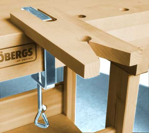
For POB, looking at the complicated - elaborate - time involved clamps in post #1, I set out to imagine a less involved way to get a similar force. I came up with an "L" shaped threaded rod. The short arm would fit into a hole drilled in the mould. There would need to be a series of holes. They would need to be drilled before attaching the mould to the spine. On the long arm: a bar of wood with a hole to slide down the rod , a washer, a wing nut. There may need to be wedge shaped shims under the bar to get direct pressure at 90 degrees on the plank. The last plank would need another sort of clamp. POF with spaces could use a straight rod - a bar inside the hull with a hole and washer/ nut at the inside end.
-
EURYALUS 1803 by Peter6172 - 1:48
Jaager replied to Peter6172's topic in - Build logs for subjects built 1801 - 1850
You could always lower the river instead of raising the bridge. What I mean is seat the floors on the keel and fit small individual fillers between them on top of the keel. The cross chock can sit on the keel also. The piece between then becomes deadwood. Since a model does not need to have water being able to communicate P to S, I prefer to have the deadwood fill the entire space between the top of the keel and the bottom of the keelson. The deadwood can be dyed black. I believe that in some vessels there was a one inch gap for the water and the rest of the space had chocks. It would look like continuous deadwood. This sort of detail was something that the shipwrights would do without it being on the plan. There were other chocks between the frames all the way to the sheer. Again, not something a designer would need to draw. -
Thanks, The general idea has been bouncing in my memory bank for a while. I first envisioned the general concept as a way to use a Pine mould for a cast hull. I read a sort of recent posting by someone scratch building a steel ship with a lot of trumblehome - for an RC project. A standard single cast plastic (epoxy?) shell would have been ideal for the model, but a solid carved hull form would not work. The standard carved hull method = layers (lamination) based on WL lines would not work. My default approach - = layers (sandwiches) based on the Body plans stations would only work if the two sections at the deadflat were three parts to allow removal. ( Unfortunate, since the carving (shaping/sanding) is so much easier, faster and an easier way to achieve accuracy . ) But Buttock lines layers would work. Three lamination would do the job. The center ( keel profile ) layer easier to extract. Too bad that I have limited my interest to the core of the wooden era 1650 - 1860. It would be an interesting experiment.
-
Should you not be able to find ready made casks and have to fabricate them: Building them over a form would mean having to turn only one master core. A solid core form would not work - it cannot be removed. The stock to be turned could be a five piece Jenga type assembly - four outer pieces and a square center piece. The form can be turned at the end of a longer five piece stick. Dowels, pins, or finish nails used to keep everything in one piece. The turning may require gluing the five with a glue that can be reversed. PVA - Iso-OH or hide glue - hot ethanol or maybe Duco - acetone. Saran Wrap. After the staves are in place and bound by the hoops, the square center of the form can be pulled out. The two opposing outer sections that are the same width as the core, be moved into the center and pulled out. Then the last two popped lose and pulled out. The staves can be paper or 3x5 card material. A power drill makes for a low cost lathe, but they do not come with 4 jaw chucks, so holding the square stock would take some work.
-
Looking for Aeropiccola Serapis instructions
Jaager replied to pinel's topic in Wood ship model kits
Pierre, H.Hahn drew up plans for the class - Roebuck 1774 - they are 1:98 - they are available for sale. A Web search should bring up a link. Given the level of quality in an Aeropiccola kit - there should be more than enough additional detail - beyond what Aero plans provide. As for instructions - there are more than a few books covering POB kit construction. The kit build log forum here should provide any how-to possibly needed. Just guessing here, but I predict the following: The number of moulds provided by the kit will not be sufficient to build a proper hull. The wood will be brittle - this not being a result of the age of the kit - this is because poor quality wood was what the kit originally provided. You will probably need to add more moulds - or use fillers. All new and better quality wood purchase probably necessary. A 44 gun frigate is a complex and difficult subject. It has all of the difficulties of a 74 gun ship - the 74 just has 2-4 times more of it OR a 100 gun ship which has 4-8 times more. Kit builders who come from a plastic background often have an unrealistic expectation for what the provided instructions contain. The more recent kits from select companies are becoming more hand holding in nature. The older kits, especially the pioneers like Aeropiccola were a lot more -you're on your own -good luck! Instruction books and journals were much more necessary. A cutter, sloop, schooner, or brig would probably be a more friendly next step. -
Used Cameron Drill Press Opinions Requested
Jaager replied to James G's topic in Modeling tools and Workshop Equipment
If you are only going to use it for wood, you might consider going with just good enough. My process requires a lot of holes. The holes have to be 90 degrees. Most all of them are #70. Top end is #50. I use the Otto Frei version of a Eurotool DRL 300.00. It has done what I have asked of it. The basic unit is an economy machine that is sold all over the place. It was $85 when I bought it. Most units seem to be ~ $120 now. I am surprised to see it for sale at Rio Grande for $70. I expect jewelry suppliers to stock the mfg output with the better QA and the bargain outfits to have the so-so units. It sounds too good to be true. I have been considering Rio Grande to be a quality outfit. A good X-Y table will cost about as much as the drill - you do not want an X-Y table with a lot of slop. A foot operated momentary switch will add to the total cost. -
I doubt that these will work as well as is wished. Do a search on Amazon for non-sterile Penrose drains.
-
2nd rate London 1656 – the art of the shipwright
Jaager replied to Waldemar's topic in Nautical/Naval History
@druxey not on paper if you are correct. But, if you look at the Navy Board framing models, the top edge and bottom edge of the overlap band look to me like they would serve the same purpose. -
Drifts
Jaager replied to tlevine's topic in Building, Framing, Planking and plating a ships hull and deck
My bias towards POF warped my view. I probably would not have guessed this. It does explain what is on display. Imagining how I would approach a model of this vessel, I cannot see trying to replicate the actual vessel's construction. Getting the outside done correctly would be challenge enough. I am totally dedicated to POF, but some hulls just look better fully planked. -
Drifts
Jaager replied to tlevine's topic in Building, Framing, Planking and plating a ships hull and deck
The heel of the port F! would start a few feet on the stb. side of the keel. The stb. F! would butt against it and be shorter. The next frame would have the stb. F1 be the longer one. Ignoring the occasional exception, I see three options for the F1/F3 frame. 1 - cross chock over the keel - several variations - the French had some complicated joinery in some ships 2 - half floor - gets interesting at the ends if it is an actual ship - easier to use Cant frames. In a model, the opposite obtains. 3 - long arm/short arm. Using half floors really reduces the length of the F1 timbers. -
2nd rate London 1656 – the art of the shipwright
Jaager replied to Waldemar's topic in Nautical/Naval History
Going by the instructions in Deane so at least up until 1670: The Body plan shape creation was only done three times during the design. The three were placed on the WL plan and battens used to define the run. The forward or aft cross sections could be moved to get the sort of entry and exit needed to theoretically favor speed or stability or capacity. Doing a mental extraction from the above premise: The complete Body plan was derived by plotting the points from the WL plan. The Diagonal plan was important to confirm that there were no problems in the run in the swimming body. I am suspecting that those who were writing an advocacy of math formulas over shipwright intuition did not gain control until about 1700. This being limited to English practice. -
Drifts
Jaager replied to tlevine's topic in Building, Framing, Planking and plating a ships hull and deck
To guess, given the evidence above: drift = a free floating rod in a hole that does not go all the way thru either the keel / floor or the keelson / floor? a heavy duty locator pin? A bolt - which is also listed - would have a head at one end and threads for a nut on the other? For your F1 between floors: The floors are long - usually ~ 60% of the beam. It seems to be forbidden - since forever - for the heels of F1 port to meet F1 stb. in the middle of the keel. It could be F1 long arm/F1 short arm - alternating. My compulsion would be to use a half floor instead - a floor timber that is ~25-30% of the beam. Have the scarph (old definition = side to side) be the same length. So those F1 would be longer - but not as long as the long arm/short arm option. -
Spell Check
Jaager replied to allanyed's topic in Using the MSW forum - **NO MODELING CONTENT IN THIS SUB-FORUM**
Well that explains why common nautical words - like futtock always get marked as being misspelled. I have been thinking that this site had selected the wrong dictionary.


